industrial networking and connectivity catalog pdfs/balluff/i_o link... · level open coil...
TRANSCRIPT

2.12
IO-LinkIO-Link connection devices
Connectivity Products with IO-Link
IO-Link’s versatility can be seen in the deep product offering covered in these pages. There are times when a standard
sensor cable is just not enough. Maybe you need to have I/O on constantly changing end effectors or a rotating fixture.
Valve banks with built in network control can add additional costs to a project. Then there are the times you wish you
could just hook the device to your computer, just to get that extra bit of interaction with the device. All of these things
are capable with IO-Link by Balluff.
Non-contact connectors allow for quick change out and free rotation without loss of power or signal
Remove costly valve bank network controllers and go to an intelligent 25-pin D-sub connector
Connect directly to any IO-Link device with your computer for easy setup or parameterization
25-pin D-sub valve
manifold connector
Non-contact connectors
Mechanical switchesUSB IO-Link Master for
parameterization or
reviewing components
USB to PC
Standard 16 input I/O hub
Court
esy
of CM
A/F
lodyn
e/H
ydra
dyn
e �
Motion C
ontr
ol �
Hyd
raulic
� P
neu
mat
ic �
Ele
ctrica
l �
Mec
han
ical
� (
800)
426-5
480 �
ww
w.c
maf
h.c
om
2.13 www.balluff.com
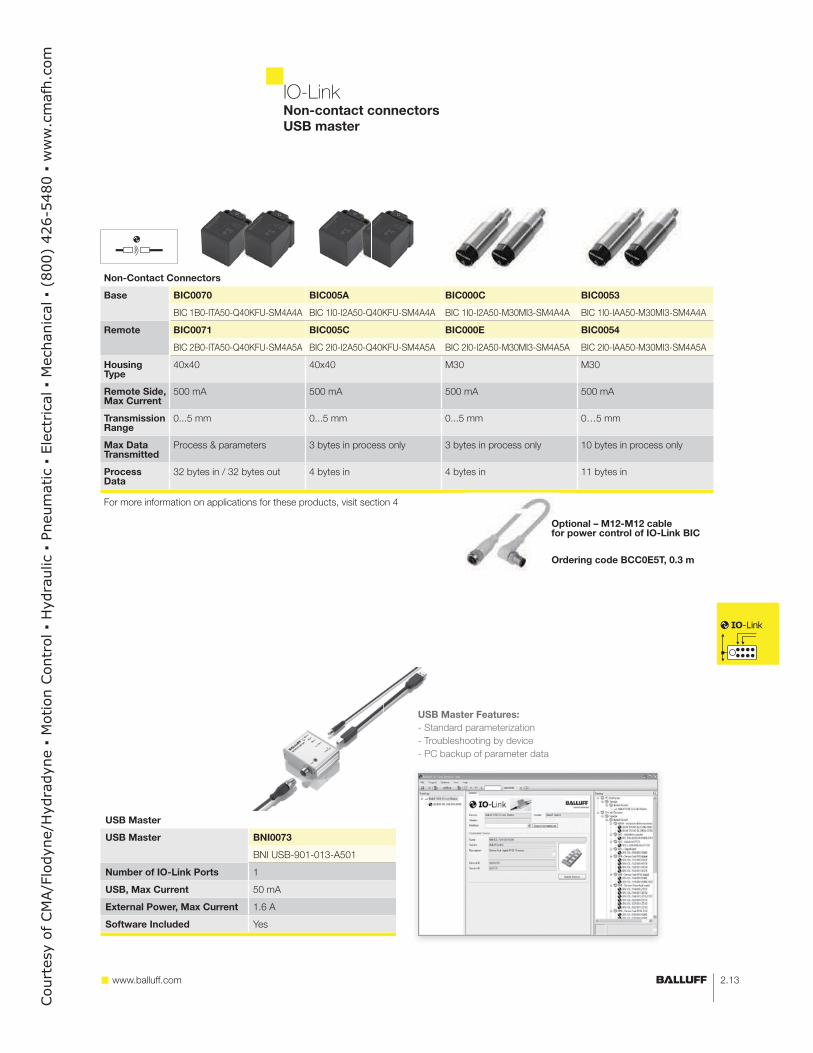
IO-LinkNon-contact connectors
USB master
Non-Contact Connectors
Base BIC0070 BIC005A BIC000C BIC0053
BIC 1B0-ITA50-Q40KFU-SM4A4A BIC 1I0-I2A50-Q40KFU-SM4A4A BIC 1I0-I2A50-M30MI3-SM4A4A BIC 1I0-IAA50-M30MI3-SM4A4A
Remote BIC0071 BIC005C BIC000E BIC0054
BIC 2B0-ITA50-Q40KFU-SM4A5A BIC 2I0-I2A50-Q40KFU-SM4A5A BIC 2I0-I2A50-M30MI3-SM4A5A BIC 2I0-IAA50-M30MI3-SM4A5A
Housing Type
40x40 40x40 M30 M30
Remote Side, Max Current
500 mA 500 mA 500 mA 500 mA
Transmission Range
0...5 mm 0...5 mm 0...5 mm 0…5 mm
Max Data Transmitted
Process & parameters 3 bytes in process only 3 bytes in process only 10 bytes in process only
Process Data
32 bytes in / 32 bytes out 4 bytes in 4 bytes in 11 bytes in
For more information on applications for these products, visit section 4
USB Master
USB Master BNI0073
BNI USB-901-013-A501
Number of IO-Link Ports 1
USB, Max Current 50 mA
External Power, Max Current 1.6 A
Software Included Yes
USB Master Features:
- Standard parameterization
- Troubleshooting by device
- PC backup of parameter data
Optional – M12-M12 cable for power control of IO-Link BIC
Ordering code BCC0E5T, 0.3 m
Court
esy
of CM
A/F
lodyn
e/H
ydra
dyn
e �
Motion C
ontr
ol �
Hyd
raulic
� P
neu
mat
ic �
Ele
ctrica
l �
Mec
han
ical
� (
800)
426-5
480 �
ww
w.c
maf
h.c
om

2.14
IO-LinkValve manifold control utilizing Distributed Modular I/O
When controls engineers get involved in specifying valve manifolds
a slippery slope can develop. Where does the mechanical design
end and the electrical design begin? Being able to order simple valve
manifolds with 25-pin D-sub connectors removes this situation and
provides multiple advantages: these valves are low cost, they are
simple to wire and they are typically standard off the shelf components
so they are easy to repair. But terminating the 25 wires and trying to
troubleshoot these multiple connections can be time consuming and
costly. By utilizing an industrial network and a Distributed Modular I/O
valve manifold connector, cost and time of installation and repair can
be dramatically reduced.
Max 0.7A per output and up to 1.1A total can be active at once
Connector provides a 0V common on pin 25 and 24V signals
Up to 16 output positions can be controlled per manifold
Up to 4 manifolds can be controlled per master device
Communication speeds between the master and valve control
of 2ms
Valve Mainifold Control over EtherNet/IP
In this conveyor application, a few cylinders are being used for gate
control to help sort packages as they come through the process.
The valve manifold has a simple 25pin D-sub connector controlling
7 positions on the conveyor. Controlling the valve manifold is a 25pin
D-sub valve manifold controller with IP40 protection. This connector
is then plugged into an EtherNet/IP master device and the controller
sees the valve manifold over the network as a simple 2 bytes of output
data. An auxiliary power output, from the master, controls the device
power and can turn on or off control to the outputs when necessary.
Four manifolds can be controlled on one EtherNet/IP master and the
manifolds can be up to 20 meters from the master device.
Parallel wiring solution
– up to 25 individual terminations
Distributed Modular I/O solution
– single connector
Valve Mainifold Control via Distributed Modular I/O
Pneumatic Systems Improvement – BMF V-Twin & Valve Manifold Control
Network Manifold with Reed Switches BMF V-Twin & Valve Manifold Control
– Centralized Air and I/O
– Congested with pipes
and cables
– Reed switches prone
to failure
– Distributed I/O and Air
– Small manifolds
mounted near actuators
– BMF V-Twin:
Less cables,
Lifetime warrantyBefore After
Court
esy
of CM
A/F
lodyn
e/H
ydra
dyn
e �
Motion C
ontr
ol �
Hyd
raulic
� P
neu
mat
ic �
Ele
ctrica
l �
Mec
han
ical
� (
800)
426-5
480 �
ww
w.c
maf
h.c
om

2.15 www.balluff.com
IO-Link
Control by Manufacturer
Connector
Type
Max
Positions
Balluff Ordering Code
Balluff Part Number
Accessory
Accessory
Description
MAC Valve Manifolds
MAConnect D-sub 25pin 16 BNI001L
BNI IOL-751-V02-K007
Bosch Rexroth Valve Manifolds
LS04, HFO2-LG, HFO3-LG, HFO4 D-sub 25pin 24 BNI001K
BNI IOL-751-V01-K007
Festo Valve Manifolds
MPA, VUVB D-sub 25pin 24 BNI001K BAM01RC For some models, cover plateBNI IOL-751-V01-K007 BAM PC-NI-009-4
CPV D-sub 25pin 8 BNI001L BAM01RC For some models, cover plateBNI IOL-751-V02-K007 BAM PC-NI-009-4
SMC Valve Manifolds
FD0 connector kit D-sub 25pin 24 BNI001M
BNI IOL-751-V03-K007
MD0 connector kit M26 26pin 24 BNI004W
BNI IOL-770-V06-A027
Numatics Valve Manifolds
AKJ connector D-sub 25pin 22 BNI006R
BNI IOL-751-V13-K007
AKF terminals screw terminals 16 BNI005M *
BNI IOL-771-000-K027
AKR connector kit M26 26pin 22 Contact Factory *
Parker Valve Manifolds
L2 End Plate Kit D-sub 25pin versions
D-sub 25pin 24 BNI001M
BNI IOL-751-V03-K007
Terminal Housing versions screw terminals 16 BNI005M *
BNI IOL-771-000-K027
Norgren Valve Manifolds
VS45 D-sub 25pin 24 BNI001M
BNI IOL-751-V03-K007
VS45 screw terminals 16 BNI005M *
BNI IOL-771-000-K027
Valve manifold control
*Consult factory for availability
Part Overview
Part Number BNI IOL-751-V_ _-K007 BNI IOL-770-V06-A027 BNI IOL-77_-000-_027*
Connection Type D-Sub 25-pin M26 26-pin IP54 flying leads
Max Active Current 1.1A 1.1A 1.1A
Output Type 24VDC outputs, OVDC commons 24VDC outputs, OVDC commons 24VDC supply, 24VDC outputs,
OVDC commons
Diagnostics basic device fault events and
information
basic device fault events, point
level open coil detection
basic device fault events and
information
Inputs/Outputs 16 or 24 outputs 24 outputs 1=16 or 2=8* configurable
Housing Material plastic metal K=plastic, A=metal*
*Consult factory for availability
Court
esy
of CM
A/F
lodyn
e/H
ydra
dyn
e �
Motion C
ontr
ol �
Hyd
raulic
� P
neu
mat
ic �
Ele
ctrica
l �
Mec
han
ical
� (
800)
426-5
480 �
ww
w.c
maf
h.c
om

2.16
IO-Link
Data Tracking with Industrial RFID using IO-Link
In today’s manufacturing environment, it is becoming more and more important to track every step of the production process.
Many manufacturers have installed barcode systems or hand written paper work filed by operators or maintenance crews.
This can be time consuming and prone to failure. Industrial RFID systems can be used to track production data and record
plant floor information in every step of the process. There are two main ways to track part data.
Centralized Data Tracking: All of the information is stored in a central computer and the RFID system is
used only for identification of the part in the work cell. This is a very similar concept to barcoding, but it is more
rugged and 100% reliable. (Read Only Systems)
Decentralized Data Tracking: Data per part is stored on the RFID tag and is written to the tag at each
workstation. This concept allows for the data to always stay with the part throughout the production process.
Radio frequency identification
Read only systems (BIS L)
For centralized data tracking
Modular base
with different heads
Read/Write systems (BIS M)
For decentralized data tracking
Longest range
Metal mounted tags
BIS L-203-03/L
BIS L-201-03/L
BIS M-112-02/L
BIS M-151-02/A
0...65 mm
0...38 mm
0...35 mm
0...7 mm
Court
esy
of CM
A/F
lodyn
e/H
ydra
dyn
e �
Motion C
ontr
ol �
Hyd
raulic
� P
neu
mat
ic �
Ele
ctrica
l �
Mec
han
ical
� (
800)
426-5
480 �
ww
w.c
maf
h.c
om

2.17 www.balluff.com
IO-LinkRFID read-only systems
Size M12 M18 25x50 40x40
IO-Link Processors
Read only
BIS00E1 BIS00E0 BIS00E2 BIS00CZ
BIS L-409-045-003-07-S4 BIS L-409-045-002-07-S4 BIS L-409-045-004-07-S4 BIS L-409-045-001-07-S4
Da
ta C
arr
iers
BIS0035 --- 0...15 mm 0...15 mm 0...25 mm
BIS L-100-05/L-RO
BIS0038 --- 0...18 mm 0...18 mm 0...35 mm
BIS L-101-05/L-RO
BIS003C --- --- --- 0...48 mm
BIS L-102-05/L-RO
BIS003F 0...7 mm 0...10 mm 0...10 mm 0...16 mm
BIS L-103-05/L-RO
BIS003R --- 0…15 mm 0…15 mm 0…25 mm
BIS L-200-03/L
BIS003T --- 0…18 mm 0…18 mm 0…35 mm
BIS L-201-03/L
BIS003U --- --- --- 0…48 mm
BIS L-202-03/L
BIS003W 0…7 mm 0…10 mm 0… 10 mm 0…16 mm
BIS L-203-03/L
Note:
The BIS L-1_ _-05/L-RO uses a single write data carrier with 192 bytes.
The BIS L-2_ _-03/L uses read only data carriers with a fixed “unique number” of five bytes (40 bits).
No repetition of the unique number or delivery of sequential numbers is possible.
All IO-Link RFID processors require a shielded cable. See page 2.19 for suggested part numbers.
Select your RFID system in 4 easy steps:
1. Decide whether you need to write data to a data carrier.
Yes see page 2.18
No see page 2.17
2. Choose the appropriate data carrier form factor.
3. Determine the head based on distance.
4. Determine your required memory capacity.
Court
esy
of CM
A/F
lodyn
e/H
ydra
dyn
e �
Motion C
ontr
ol �
Hyd
raulic
� P
neu
mat
ic �
Ele
ctrica
l �
Mec
han
ical
� (
800)
426-5
480 �
ww
w.c
maf
h.c
om

2.18
IO-LinkRFID read/write systems
Standard and metal mount data carriers
Size M15.5 M18
IO-Link Processors 10 bytes BIS00LJ BIS00LW
BIS M-400-045-002-07-S4 BIS M-402-045-002-07-S4
IO-Link Processors 32 bytes BIS0104 BIS0105
BIS M-400-072-002-07-S4 BIS M-402-072-002-07-S4
Read/Write Heads
Sta
nd
ard
Da
ta C
arr
iers
752 bytes 2000 bytes 8000 bytes*
BIS0048 BIS004A 0…5(6) mm 0…5 mm
BIS M-122-01/A BIS M-122-02/A
BIS0040 BIS0042 0…6(9) mm 0…5 mm
BIS M-105-01/A BIS M-105-02/A
BIS0044 0…15 mm 0…8 mm
BIS M-110-02/L
BIS003Y 0…15 mm
BIS M-101-01/L
BIS003Z 0…18 mm
BIS M-102-01/L
BIS0043 BIS0111 0…20 m
BIS M-108-02/L BIS M-108-20/A
BIS0045 0…20 mm
BIS M-111-02/L
BIS0046 0…28 mm
BIS M-112-02/L
BIS0047
BIS M-120-01/L
Size 80x84
IO-Link Processors 10 bytes BIS00LM
BIS M-451-045-001-07-S4
IO-Link Processors 32 bytes BIS0103
BIS M-451-072-001-07-S4
Read/Write Heads
Me
tal M
ou
nt
D
ata
Ca
rrie
rs BIS004F 0…65 mm
BIS M-150-02/A (vertical mount)
BIS004H 0…65 mm
BIS M-151-02/A (horizontal mount)
* only for use with 32 byte processors
For reliable traceability: All data carriers have a 4-byte unique ID contained in the read/write memory. This number is read-only. All IO-Link RFID processors require a shielded cable. See page 2.19 for suggested part numbers.
Metal Mount Series: These tags provide highly reliable RFID performance mounted on any metal surface.
Features: - No reduction in range, regardless of metal alloy - Large read/write range - Compatible with all M processors
Metal mounting plate 40x22mm BIS Z-MP-001 please order separately (10 to a package). Required if no metal substrate is used.
s
Court
esy
of CM
A/F
lodyn
e/H
ydra
dyn
e �
Motion C
ontr
ol �
Hyd
raulic
� P
neu
mat
ic �
Ele
ctrica
l �
Mec
han
ical
� (
800)
426-5
480 �
ww
w.c
maf
h.c
om
2.19 www.balluff.com
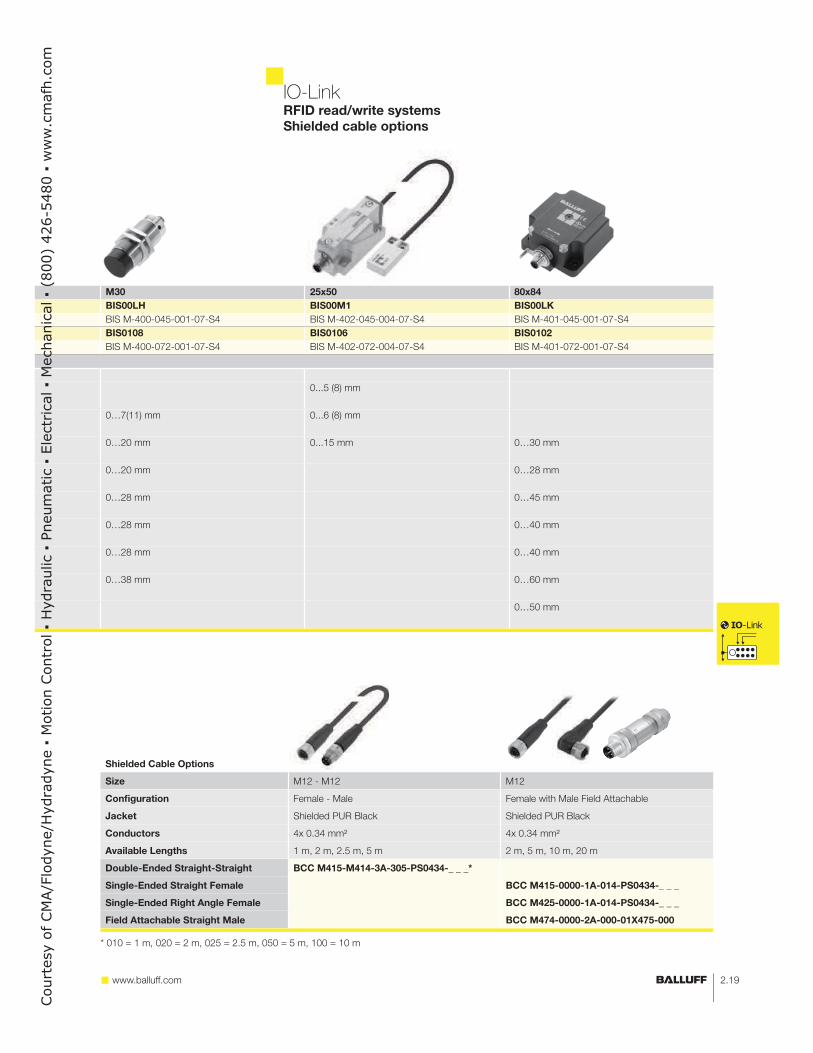
IO-LinkRFID read/write systems
Shielded cable options
M30 25x50 80x84
BIS00LH BIS00M1 BIS00LK
BIS M-400-045-001-07-S4 BIS M-402-045-004-07-S4 BIS M-401-045-001-07-S4
BIS0108 BIS0106 BIS0102
BIS M-400-072-001-07-S4 BIS M-402-072-004-07-S4 BIS M-401-072-001-07-S4
0...5 (8) mm
0…7(11) mm 0...6 (8) mm
0…20 mm 0...15 mm 0…30 mm
0…20 mm 0…28 mm
0…28 mm 0…45 mm
0…28 mm 0…40 mm
0…28 mm 0…40 mm
0…38 mm 0…60 mm
0…50 mm
Shielded Cable Options
Size M12 - M12 M12
Configuration Female - Male Female with Male Field Attachable
Jacket Shielded PUR Black Shielded PUR Black
Conductors 4x 0.34 mm² 4x 0.34 mm²
Available Lengths 1 m, 2 m, 2.5 m, 5 m 2 m, 5 m, 10 m, 20 m
Double-Ended Straight-Straight BCC M415-M414-3A-305-PS0434-_ _ _*
Single-Ended Straight Female BCC M415-0000-1A-014-PS0434-_ _ _
Single-Ended Right Angle Female BCC M425-0000-1A-014-PS0434-_ _ _
Field Attachable Straight Male BCC M474-0000-2A-000-01X475-000
* 010 = 1 m, 020 = 2 m, 025 = 2.5 m, 050 = 5 m, 100 = 10 m
Court
esy
of CM
A/F
lodyn
e/H
ydra
dyn
e �
Motion C
ontr
ol �
Hyd
raulic
� P
neu
mat
ic �
Ele
ctrica
l �
Mec
han
ical
� (
800)
426-5
480 �
ww
w.c
maf
h.c
om

2.20
IO-Link
Printing and Paper Example
Reliable diagnostics are extremely important for highly dynamic
machines. You can identify quality issues linked to the manufacturing
process in real-time and take appropriate measures immediately. In the
printing and paper machine industry, for example, the machine must
react to faults within milliseconds.
Color Sensor Example
While running project A, the color sensor is configured to detect the dif-
ference between five different colors as parts are loaded into a fixture.
After the required parts are run off, a new project is begun with
a different color set. In the past, a second color sensor would be
required, or the operator would have to reprogram the current sensor
for each new color. By using device parameterization, the controller
tells the sensor its configuration for project B and quickly, without
hassle, the sensor has its new colors.
Green Orange
Project A
Project B
Red Blue
Advantages of intelligent sensors
Applications of intelligent sensors
As manufacturing becomes
even more competitive and the
demand for flexibility rises, we
begin to ask tough questions to
ourselves, our machine builders
and our component suppliers:
How do I increase my produc-
tion throughput and maintain
quality?
How can I predict sensor or
machine failure?
What can I do to decrease my
unplanned downtime?
Where and how often are
most failures occurring?
How do I get more detailed
information out of the system?
The ideal solution to these
questions is a system that can
easily provide status information
from the health of a PLC and
industrial network down to the
individual sensor location at one
work station. The system could
predict impending issues and
automatically direct action to
solve the issue before it causes
production to stop. In addition
the system should be able to
be flexible and adjust to multiple
configurations, sizes, colors, etc.
Intelligent sensors are part of this solution. By providing Constant Condition Monitoring, Preventative
Diagnostics and Automatic Configuration over common industrial networks, intelligent sensors
provide the flexibility and detailed data required in a modern manufacturing facility.
Detailed sensor information
Exact failure location
“I’m working!”
ConstantConditionMonitoring
Over the industrial network
Sensor health indication
Standard indication (ON/OFF, measurement,etc.)
Decreasing unplanned downtime
Predicting failures
“Something changed!”
Unstable application diagnostics
– Dirty lens
– Target too close
– Target outside ideal range
Increasing equipment throughput
Increasing process reliability
Maintaining high quality
“Tell me what to do!”
Parameter configuration
– Remote program from the PLC
– Multiple Configurations stored on the PLC
– Control over features and functions
PreventativeDiagnostics
Automatic
Configuration
Court
esy
of CM
A/F
lodyn
e/H
ydra
dyn
e �
Motion C
ontr
ol �
Hyd
raulic
� P
neu
mat
ic �
Ele
ctrica
l �
Mec
han
ical
� (
800)
426-5
480 �
ww
w.c
maf
h.c
om

2.21 www.balluff.com
IO-LinkUltrasonic sensors
Scanning range 20…150 mm 30…250 mm
Straight
Resolution 0.069 mm 0.069 mm
push/pull NO/NC
IO-Link
Ordering code BUS0020 BUS0029
Part number BUS M18M1-GPXI-02/015-S92G BUS M18M1-GPXI-03/025-S92G
Angled
Resolution 0.069 mm 0.069 mm
push/pull NO/NC
IO-Link
Ordering code BUS0023 BUS002A
Part number BUS W18M1-GPXI-02/015-S92G BUS W18M1-GPXI-03/025-S92G
Size M18×1 M18×1
Supply voltage 10...30 V DC 10...30 V DC
Output current 200 mA 200 mA
Degree of protection as per EN 60529 IP 67 IP 67
Operating temperature –25...+70 °C –25...+70 °C
Material Housing Nickel-plated brass tube Nickel-plated brass tube
Plastic parts PBT PBT
Sensing surface Polyurethane foam, epoxy resin
containing glass
Polyurethane foam, epoxy resin
containing glass
Connection M12 connector,
5-pin
M12 connector,
5-pin
Scanning range 65…350 mm 120…1000 mm
Straight
Resolution 0.069 mm 0.069 mm
push/pull NO/NC
IO-Link
Ordering code BUS004Z BUS004P
Part number BUS M18M1-GPXI-07/035-S92G BUS M18M1-GPXI-12/100-S92G
Angled
Resolution 0.069 mm 0.069 mm
push/pull NO/NC
IO-Link
Ordering code BUS004Y BUS004N
Part number BUS W18M1-GPXI-07/035-S92G BUS W18M1-GPXI-12/100-S92G
Size M18×1 M18×1
Supply voltage 10...30 V DC 10...30 V DC
Output current 200 mA 200 mA
Degree of protection as per EN 60529 IP 67 IP 67
Operating temperature –25...+70 °C –25...+70 °C
Material Housing Nickel-plated brass tube Nickel-plated brass tube
Plastic parts PBT PBT
Sensing surface Polyurethane foam, epoxy resin
containing glass
Polyurethane foam, epoxy resin
containing glass
Connection M12 connector,
5-pin
M12 connector,
5-pin
Automatic
ConfigurationPreventativeDiagnostics
ONOFF
MeasureConstantConditionMonitoring
Automatic
ConfigurationPreventativeDiagnostics
ONOFF
MeasureConstantConditionMonitoring
Court
esy
of CM
A/F
lodyn
e/H
ydra
dyn
e �
Motion C
ontr
ol �
Hyd
raulic
� P
neu
mat
ic �
Ele
ctrica
l �
Mec
han
ical
� (
800)
426-5
480 �
ww
w.c
maf
h.c
om

2.22
IO-LinkFluid detection – BSP Pressure sensors
Manometer screw
connection per
DIN EN 837
–1...2 bar (–14.5...29 psi) Ordering code BSP0086 BSP008L
Part number BSP V002-EV002-D00S1B-S4 BSP V002-EV002-A00S1B-S4
–1...10 bar (–14.5...145 psi) Ordering code BSP0087 BSP008M
Part number BSP V010-EV002-D00S1B-S4 BSP V010-EV002-A00S1B-S4
0...2 bar (0...29 psi) Ordering code BSP0088 BSP008N
Part number BSP B002-EV002-D00S1B-S4 BSP B002-EV002-A00S1B-S4
0...5 bar (0...73 psi) Ordering code BSP0089 BSP008P
Part number BSP B005-EV002-D00S1B-S4 BSP B005-EV002-A00S1B-S4
0...10 bar (0...145 psi) Ordering code BSP008A BSP008R
Part number BSP B010-EV002-D00S1B-S4 BSP B010-EV002-A00S1B-S4
0...20 bar (0...290 psi) Ordering code BSP008C BSP008T
Part number BSP B020-EV002-D00S1B-S4 BSP B020-EV002-A00S1B-S4
0...50 bar (0...725 psi) Ordering code BSP008E BSP008U
Part number BSP B050-EV002-D00S1B-S4 BSP B050-EV002-A00S1B-S4
0...100 bar (0...1450 psi) Ordering code BSP008F BSP008W
Part number BSP B100-EV002-D00S1B-S4 BSP B100-EV002-A00S1B-S4
0...250 bar (0...3626 psi) Ordering code BSP008H BSP008Y
Part number BSP B250-EV002-D00S1B-S4 BSP B250-EV002-A00S1B-S4
0...400 bar (0...5802 psi) Ordering code BSP008J BSP008Z
Part number BSP B400-EV002-D00S1B-S4 BSP B400-EV002-A00S1B-S4
0...600 bar (0...8702 psi) Ordering code BSP008K BSP0090
Part number BSP B600-EV002-D00S1B-S4 BSP B600-EV002-A00S1B-S4
Housing Material PA 6.6 and stainless steel PA 6.6 and stainless steel
Plug connector M12 connector, 4-pin M12 connector, 4-pin
Process connection Internal thread G¼" per DIN EN 3852 Internal thread G¼" per DIN EN 3852
PNP pressure sensors
Design Relative nominal pressure Overload pressure Burst pressure Permitted vacuum
-1...2 bar 29 psi 2 bar 58 psi 4 bar 145 psi 10 bar
vacuum
pro
of
-1...10 bar 145 psi 10 bar 290 psi 20 bar 508 psi 35 bar
0...2 bar 29 psi 2 bar 58 psi 4 bar 145 psi 10 bar
0...5 bar 73 psi 5 bar 145 psi 10 bar 218 psi 15 bar
0...10 bar 145 psi 10 bar 290 psi 20 bar 508 psi 35 bar
0...20 bar 290 psi 20 bar 580 psi 40 bar 1088 psi 75 bar
0...50 bar 725 psi 50 bar 1450 psi 100 bar 2176 psi 150 bar
0...100 bar 1450 psi 100 bar 2900 psi 200 bar 3626 psi 250 bar
0...250 bar 3626 psi 250 bar 5802 psi 400 bar 6527 psi 450 bar
0...400 bar 5802 psi 400 bar 9428 psi 650 bar 10153 psi 700 bar
0...600 bar 8702 psi 600 bar 10878 psi 750 bar 11603 psi 800 bar
Ordering code BAM01KP BAM01KR BAM01UJ
Part number BAM AD-SP-008-1G4/1G4-4 BAM AD-SP-008-1G4/1G4-4-EN837 BAM AD-SP-008-1G4/1G2-4
Process Connection G1/4" G1/4" G1/4"
Electrical Connection G1/4" G1/4" G1/2"
BSP Accessories
Two switching points
(NO or NC)
One switching point and
analog output 0...10 V DC
Court
esy
of CM
A/F
lodyn
e/H
ydra
dyn
e �
Motion C
ontr
ol �
Hyd
raulic
� P
neu
mat
ic �
Ele
ctrica
l �
Mec
han
ical
� (
800)
426-5
480 �
ww
w.c
maf
h.c
om

2.23 www.balluff.com
IO-LinkBSP Pressure sensor accessories
Internal thread
BSP0091 BSP004Y BSP0050 BSP0052
BSP V002-EV002-A02S1B-S4 BSP V002-EV003-D00A0B-S4 BSP V002-EV003-A00A0B-S4 BSP V002-EV003-A02A0B-S4
BSP0092 BSP004Z BSP0051 BSP0053
BSP V010-EV002-A02S1B-S4 BSP V010-EV003-D00A0B-S4 BSP V010-EV003-A00A0B-S4 BSP V010-EV003-A02A0B-S4
BSP0093 BSP0021 BSP002A BSP002N
BSP B002-EV002-A02S1B-S4 BSP B002-EV003-D00A0B-S4 BSP B002-EV003-A00A0B-S4 BSP B002-EV003-A02A0B-S4
BSP0094 BSP0022 BSP002C BSP002P
BSP B005-EV002-A02S1B-S4 BSP B005-EV003-D00A0B-S4 BSP B005-EV003-A00A0B-S4 BSP B005-EV003-A02A0B-S4
BSP0095 BSP0023 BSP002E BSP002R
BSP B010-EV002-A02S1B-S4 BSP B010-EV003-D00A0B-S4 BSP B010-EV003-A00A0B-S4 BSP B010-EV003-A02A0B-S4
BSP0096 BSP0024 BSP002F BSP002T
BSP B020-EV002-A02S1B-S4 BSP B020-EV003-D00A0B-S4 BSP B020-EV003-A00A0B-S4 BSP B020-EV003-A02A0B-S4
BSP0097 BSP0025 BSP002H BSP002U
BSP B050-EV002-A02S1B-S4 BSP B050-EV003-D00A0B-S4 BSP B050-EV003-A00A0B-S4 BSP B050-EV003-A02A0B-S4
BSP0098 BSP0026 BSP002J BSP002W
BSP B100-EV002-A02S1B-S4 BSP B100-EV003-D00A0B-S4 BSP B100-EV003-A00A0B-S4 BSP B100-EV003-A02A0B-S4
BSP0099 BSP0027 BSP002K BSP002Y
BSP B250-EV002-A02S1B-S4 BSP B250-EV003-D00A0B-S4 BSP B250-EV003-A00A0B-S4 BSP B250-EV003-A02A0B-S4
BSP009A BSP0028 BSP002L BSP002Z
BSP B400-EV002-A02S1B-S4 BSP B400-EV003-D00A0B-S4 BSP B400-EV003-A00A0B-S4 BSP B400-EV003-A02A0B-S4
BSP009C BSP0029 BSP002M BSP0030
BSP B600-EV002-A02S1B-S4 BSP B600-EV003-D00A0B-S4 BSP B600-EV003-A00A0B-S4 BSP B600-EV003-A02A0B-S4
PA 6.6 and stainless steel Stainless steel Stainless steel Stainless steel
M12 connector, 4-pin M12 connector, 4-pin M12 connector, 4-pin M12 connector, 4-pin
Internal thread G¼" per DIN EN 3852 Internal thread G¼” per DIN EN 3852 Internal thread G¼” per DIN EN 3852 Internal thread G¼” per DIN EN 3852
BAM0209 BAM01RP BAM01KT BAM01TR
BAM AD-SP-008-1G4/M20X1.5-4 BAM AD-SP-008-1G4/1R4-4 BAM AD-SP-008-1G4/1N4-4 BAM AD-SP-011-1G4/1N4-4
G1/4" G1/4" G1/4" 1/4" NPT
M20x1.5 R1/4" NPT1/4" Internal Thread NPT1/4"
One switching point and
analog output 4...20 mA
Two switching points
(NO or NC)
One switching point and
analog output 0...10 V DC
One programmable point
and analog output 4...20 mA
Court
esy
of CM
A/F
lodyn
e/H
ydra
dyn
e �
Motion C
ontr
ol �
Hyd
raulic
� P
neu
mat
ic �
Ele
ctrica
l �
Mec
han
ical
� (
800)
426-5
480 �
ww
w.c
maf
h.c
om

2.24
IO-LinkIO-Link intelligent sensors
Inductive Positioning Sensors
Ordering Code BIP0004
Part Number BIP LD2-T040-02-S4
Range 0...40 mm
Target Width 14 mm
Resolution 40 μm
Process Data 2 bytes
Inductive Measurement Sensors
Ordering Code BAW002F BAW003A
Part Number BAW M18MI-BLC50B-S04G BAW Z01AC-BLD50B-DP03
Range 1...5 mm 1...5 m
Switch Points 0 3
Resolution ± 8 μm ± 10 μm
Analog Value Range 0000...03FF 0000...03FF
Process Data 3 bytes 2 bytes
Laser Measurement Sensors
Ordering Code BOD0012
Part Number BOD 63M-LI06-S4
Range 200...6000 mm
Resolution 1 mm
Repeatability ± 4 mm
Analog Value Range 00C8...1770
Process Data 3 bytes/1 byte
Mechanical Switches
Part Number BNS 819-...
Housing Series Available 40, 46, 61, 62, 100
Measure
Automatic
ConfigurationPreventativeDiagnostics
ConstantConditionMonitoring
ONOFF
MeasureConstantConditionMonitoring
ONOFF
ConstantConditionMonitoring
Automatic
ConfigurationPreventativeDiagnostics
ONOFF
MeasureConstantConditionMonitoring
PreventativeDiagnostics
MeasureConstantConditionMonitoring
Inductive Sensors
Ordering code BES04FK
Part number BES M12MI-PSIC20L-S04G
Range 0.5...2mm program
SIO mode yes
Process data 1 byte
Automatic
ConfigurationPreventativeDiagnostics
ONOFF
MeasureConstantConditionMonitoring
Court
esy
of CM
A/F
lodyn
e/H
ydra
dyn
e �
Motion C
ontr
ol �
Hyd
raulic
� P
neu
mat
ic �
Ele
ctrica
l �
Mec
han
ical
� (
800)
426-5
480 �
ww
w.c
maf
h.c
om

2.25 www.balluff.com
IO-LinkIO-Link intelligent sensors
Edge Detection
30 mm Ordering Code BGL0035
Part Number BGL 30C-007-S4
50 mm Ordering Code BGL003F
Part Number BGL 50C-007-S4
Resolution 0.08 mm
Light Spot 28 mm x 3 mm
Air Blowoff Built-in
Analog Value Range 0...1024
Automatic
ConfigurationPreventativeDiagnostics
ONOFF
MeasureConstantConditionMonitoring
Color Sensing
Ordering Code BFS000F
Part Number BFS 26K-GI-L04-S92
Diffuse Range 12…32 mm
Reflector Range 50…200 mm
Working Colors 5
Process Data 1 byte
Light Spot Ø4 mm at 22 mm
Automatic
ConfigurationONOFF
ConstantConditionMonitoring
Automatic
ConfigurationPreventativeDiagnostics
MeasureConstantConditionMonitoring
Linear Position Transducer
Ordering Code
Part Number BTL6-U100-M_ _ _ _-PF-S4*
Stroke Length 50 mm...4572 mm (2" to 180")
Resolution 5 μm
Analog Value Range 32 bit signed integer
*Consult factory for availability
Ordering Instructions:
M_ _ _ _ = desired stroke length in mm (0051 to 4572)
Photoelectric BOS 50K - Diffuse sensor
Ordering Code BOS01JJ
Part Number BOS 50K-PI-RD11-S4
Scanning range 1...3500 mm
Light type Red light
Supply voltage UB
10...30 VDC
Interface IO-Link
Setting/configuration Teach-in or IO-Link
Switching frequency 200 Hz
Housing material PC/ABS
Optical surface Glass
Degree of protection IP 67
Ambient temperature Ta
–5 to +55°C
Connection M12 connector, 4-pin
Automatic
ConfigurationPreventativeDiagnostics
ONOFF
MeasureConstantConditionMonitoring
Court
esy
of CM
A/F
lodyn
e/H
ydra
dyn
e �
Motion C
ontr
ol �
Hyd
raulic
� P
neu
mat
ic �
Ele
ctrica
l �
Mec
han
ical
� (
800)
426-5
480 �
ww
w.c
maf
h.c
om

2.26
IO-LinkSmartLight – for signaling operating states
Stack light & visualization functions with one configurable part number
Whether you are a machine builder interested in reducing the total cost of your machine or an end-user trying to keep your machine operational
on a daily basis, the selection of control components can directly impact your success. This is even more true when it comes to the selection
of status indicators in your process. It is also important for workers like operators, fork truck drivers, maintenance, and management to clearly
and visually understand the status of their workstation, their next load, their next fix or understand the bottlenecks in the production. In these
types of applications a stack light or HMI is typically integrated to communicate the status of the process. By using a software-configurable
SmartLight to indicate machine status, you can simplify the visual indication with a single part number that costs less than most HMIs.
The Balluff SmartLight can be connected to virtually any industrial network via the open and universal standard, IO-Link. This device can be
used with a variety of IP67 distributed modular I/O products offered from a variety of IO-Link vendors which eliminates the need to have a
remote I/O box simply to control an indicator light. Balluff’s SmartLight can function in any of three modes, can be configured on the fly, and is
controlled using simple bitmaps for the outputs.
Stack Light Process Indication
Stack lights in use today come in an overwhelming variety of options and configurations that can
make keeping the right spare parts and light bulbs in the store room frustrating. This happens for
end users because the equipment comes in with a variety of hardware or because the machine
builders’ customers specify all different brands and configurations. The SmartLight allows for
one part number to cover all applications. Since this device uses an industry standard M12
connector and is IP54, it can be mounted right on the machine for simple and quick installation
without the need for a remote I/O box or multiple terminations in the controller.
Level Visualization
Sometimes there is a need to communicate status beyond just on/off or the need to visualize
a measurement or speed. These kinds of indications can be expensive, requiring an HMI for a
simple meter, a digital bar meter, or a display with analog outputs. Other costly elements like an
enclosure and remote I/O devices could also be needed. The SmartLight’s level mode can be
used for a variety of indications such as: machine speed, throughput, output quality, operator
performance to quota, position of a part, feeder bowl level, hopper level, container level, tank
level, output bin level, kanban systems, or pick-to-light.
Stack Light Mode
■ Program 1-5 positions of 20 rows of 360° LEDs
■ Choose from 5 standard colors or configure new
■ Easily switch between solid, flashing, and blinking
Level Mode
■ Tie a bar meter type scale to an analog value
■ Program high level or low level indication
■ Freely configure the colors, zones, and levels
Run Mode
■ Indicate running status with a simple scrolling light
■ Signal a problem or action required
■ Freely configure the color or the scrolling light, background, and speed
Stack Light Mode Level Mode Run Mode
Court
esy
of CM
A/F
lodyn
e/H
ydra
dyn
e �
Motion C
ontr
ol �
Hyd
raulic
� P
neu
mat
ic �
Ele
ctrica
l �
Mec
han
ical
� (
800)
426-5
480 �
ww
w.c
maf
h.c
om

2.27 www.balluff.com
IO-LinkSmartLight
IO-Link Device Device Device
Designation SmartLight with buzzer, 1-5 zones SmartLight, 1-5 zones SmartLight, 1-3 zones
Ordering code BNI0085 BNI0072 BNI007F
Part number BNI IOL-802-102-Z037 BNI IOL-802-000-Z036 BNI IOL-801-000-Z036
Supply voltage UB 18...30 V DC 18...30 V DC 18...30 V DC
Function indicator IO-Link RUN Green LED Green LED Green LED
Power-on indicator Green LED Green LED Green LED
Connection: IO-Link M12, A-coded, male M12, A-coded, male M12, A-coded, male
Connection UA
via IO-Link interface via IO-Link interface via IO-Link interface
Configurable Yes Yes Yes
Max. load current of actuators 0.35 A 0.35 A 0.35 A
Degree of protection as per IEC
60529
IP 54 (only in plugged-in and
screwed-down state)
IP 54 (only in plugged-in and
screwed-down state)
IP 54 (only in plugged-in and
screwed-down state)
Operating temperature Ta
–5…+70 °C –5…+70 °C –5…+70 °C
Storage temperature –25…+70 °C –25…+70 °C –25…+70 °C
Mounting M18 thread M18 thread M18 thread
Dimensions (L×W×H) 55×55×295 mm 55×55×295 mm 55×55×213 mm
Housing material Transparent polycarbonate,
nickel-plated die-cast zinc
Transparent polycarbonate,
nickel-plated die-cast zinc
Transparent polycarbonate,
nickel-plated die-cast zinc
IO-Link Version 1.1
Transfer rate COM 2 (38.4 kBaud) COM 2 (38.4 kBaud) COM 2 (38.4 kBaud)
Cycle time 5 ms with IO-Link 1.1 Master
20 ms with IO-Link 1.0 Master
5 ms with IO-Link 1.1 Master
20 ms with IO-Link 1.0 Master
5 ms with IO-Link 1.1 Master
20 ms with IO-Link 1.0 Master
Indicators Communication Flashing green LED Flashing green LED Flashing green LED
Power supply Static green LED Static green LED Static green LED
IO-Link process data length 3 byte output 3 byte output 3 byte output
Part number Description
BAM0255 Wall Mount, Right Angle Bracket
SET014H Pole or Wall Mount, 150 mm Al Rod, Variable Foot, Knuckle & M18 Bracket
SET014J Pole or Wall Mount, 250 mm Al Rod, Variable Foot, Knuckle & M18 Bracket
Court
esy
of CM
A/F
lodyn
e/H
ydra
dyn
e �
Motion C
ontr
ol �
Hyd
raulic
� P
neu
mat
ic �
Ele
ctrica
l �
Mec
han
ical
� (
800)
426-5
480 �
ww
w.c
maf
h.c
om