industrial fuel cleaner & transfer system diesel fuel … · the digital flow meter/nozzle is a...
TRANSCRIPT
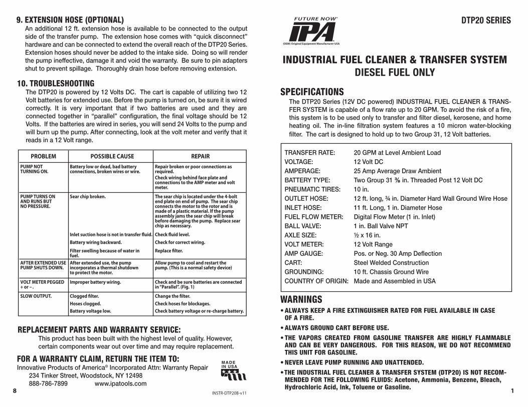
TRANSFER RATE: 20 GPM at Level Ambient LoadVOLTAGE: 12 Volt DCAMPERAGE: 25 Amp Average Draw AmbientBATTERY TYPE: Two Group 31 ⅜ in. Threaded Post 12 Volt DCPNEUMATIC TIRES: 10 in.OUTLET HOSE: 12 ft. long, ¾ in. Diameter Hard Wall Ground Wire HoseINLET HOSE: 11 ft. Long, 1 in. Diameter HoseFUEL FLOW METER: Digital Flow Meter (1 in. Inlet)BALL VALVE: 1 in. Ball Valve NPTAXLE SIZE: ½ x 16 in.VOLT METER: 12 Volt RangeAMP GAUGE: Pos. or Neg. 30 Amp DeflectionCART: Steel Welded ConstructionGROUNDING: 10 ft. Chassis Ground WireCOUNTRY OF ORIGIN: Made and Assembled in USA
DTP20 SERIES
INDUSTRIAL FUEL CLEANER & TRANSFER SYSTEMDIESEL FUEL ONLY
WARNINGS• ALWAYS KEEP A FIRE EXTINGUISHER RATED FOR FUEL AVAILABLE IN CASE
OF A FIRE.• ALWAYS GROUND CART BEFORE USE.• THE VAPORS CREATED FROM GASOLINE TRANSFER ARE HIGHLY FLAMMABLE
AND CAN BE VERY DANGEROUS. FOR THIS REASON, WE DO NOT RECOMMEND THIS UNIT FOR GASOLINE.
• NEVER LEAVE PUMP RUNNING AND UNATTENDED.• THE INDUSTRIAL FUEL CLEANER & TRANSFER SYSTEM (DTP20) IS NOT RECOM-
MENDED FOR THE FOLLOWING FLUIDS: Acetone, Ammonia, Benzene, Bleach, Hydrochloric Acid, Ink, Toluene or Gasoline.
SPECIFICATIONSThe DTP20 Series (12V DC powered) INDUSTRIAL FUEL CLEANER & TRANS-FER SYSTEM is capable of a flow rate up to 20 GPM. To avoid the risk of a fire, this system is to be used only to transfer and filter diesel, kerosene, and home heating oil. The in-line filtration system features a 10 micron water-blocking filter. The cart is designed to hold up to two Group 31, 12 Volt batteries.
INSTR-DTP20B-v11
FOR A WARRANTY CLAIM, RETURN THE ITEM TO: Innovative Products of America® Incorporated Attn: Warranty Repair
234 Tinker Street, Woodstock, NY 12498 888-786-7899 www.ipatools.com
REPLACEMENT PARTS AND WARRANTY SERVICE:This product has been built with the highest level of quality. However, certain components wear out over time and may require replacement.
PUMP TURNS ONAND RUNS BUTNO PRESSURE.
PUMP NOTTURNING ON.
PROBLEM POSSIBLE CAUSE REPAIR
AFTER EXTENDED USE PUMP SHUTS DOWN.
VOLT METER PEGGED+ or - .
SLOW OUTPUT.
Battery low or dead, bad battery connections, broken wires or wire.
Sear chip broken.
Inlet suction hose is not in transfer �uid.Battery wiring backward.
Filter swelling because of water in fuel.After extended use, the pump incorporates a thermal shutdown to protect the motor.
Improper battery wiring.
Clogged �lter.Hoses clogged.Battery voltage low.
Repair broken or poor connections as required.Check wiring behind face plate and connections to the AMP meter and volt meter.
The sear chip is located under the 4-bolt end plate on end of pump. The sear chip connects the motor to the rotor and is made of a plastic material. If the pump assembly jams the sear chip will break before damaging the pump. Replace sear chip as necessary.
Check �uid level.Check for correct wiring.
Replace �lter.
Allow pump to cool and restart the pump. (This is a normal safety device)
Check and be sure batteries are connected in “Parallel”. (Fig. 1)
Change the �lter.Check hoses for blockages.Check battery voltage or re-charge battery.
10. TROUBLESHOOTINGThe DTP20 is powered by 12 Volts DC. The cart is capable of utilizing two 12 Volt batteries for extended use. Before the pump is turned on, be sure it is wired correctly. It is very important that if two batteries are used and they are connected together in “parallel” configuration, the final voltage should be 12 Volts. If the batteries are wired in series, you will send 24 Volts to the pump and will burn up the pump. After connecting, look at the volt meter and verify that it reads in a 12 Volt range.
9. EXTENSION HOSE (OPTIONAL)An additional 12 ft. extension hose is available to be connected to the output side of the transfer pump. The extension hose comes with “quick disconnect” hardware and can be connected to extend the overall reach of the DTP20 Series. Extension hoses should never be added to the intake side. Doing so will render the pump ineffective, damage it and void the warranty. Be sure to pin adapters shut to prevent spillage. Thoroughly drain hose before removing extension.
8 1
1. BATTERY INSTALLATIONPRIOR TO REMOVING THE BATTERY, BE CERTAIN TO COMPLETELY CLEAN ANY FUEL OIL IN THE BATTERY AREA. AVOID ARCING!
TO REMOVE THE BATTERY PROTECTION COVER: Remove the screws and slide the plate out towards the back. Then install two well-charged Group 31, 12 Volt Batteries. One well-charged Group 31 Battery can last up to four hours and eight hours with two batteries. When installing batteries, keep in mind that only proper parallel wiring polarity produces 12 Volts (See Fig. 1). DO NOT WIRE BATTERIES IN SERIES AS THIS BRINGS THE POWER UP TO 24 VOLTS, DAMAGE THE UNIT AND POSSIBLY CAUSE A FIRE. THIS VOIDS THE WARRANTY.
After proper installation of batteries, check the volt meter for correct 12 Volt indication. Slide the battery protection cover back over the batteries and reinsert the screws. Be careful not to touch the battery terminals with the metal cover; you could create a spark and ignite any nearby fuel or oil.
SET UP
2 7
CORRECT BATTERY INSTALLATION:WARNING: FOR SAFE INSTALLATION, CONNECT 12 VOLT BATTERIES IN PARALLEL WITH POSITIVE TO POSITIVE AND NEGATIVE TO NEGATIVE. ANY OTHER CONFIGU-RATION IS INCORRECT AND WILL DAMAGE THE PUMP AND VOID THE WARRANTY.
• DO NOT TRANSFER GASOLINE: Although the DTP20 DC powered transfer pump can transfer gasoline and no damage will occur to the pump, it is NOT recom-mended. Because of the DC application of the fuel transfer cart, there is a potential danger of battery sparks igniting gasoline that may have spilled or collected on the cart from prior use. One gallon of gasoline is equivalent to three sticks of dynamite and the possibility of great harm or bodily injury exists if ignited. Please also be careful in calm or dry climate as this increases the risk of static. ALWAYS USE THE GROUND WIRE PROVIDED.
• THE DTP20 IS RECOMMENDED FOR TRANSFERRING OF THE FOLLOWING FLUIDS: Diesel, Kerosene, Heptanes, Mineral Spirits and Hexane.
• NO SMOKING or any type of ignition. No exceptions.
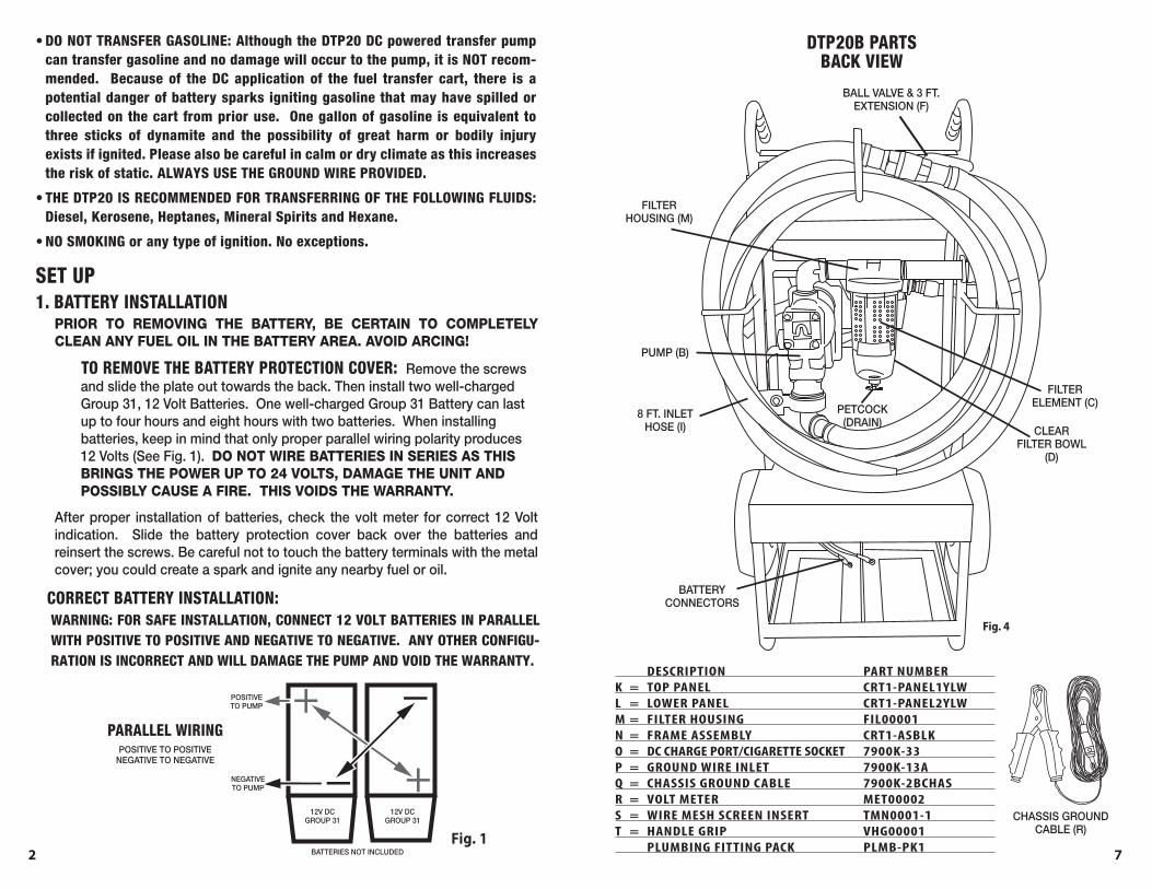
Fig. 4
DTP20B PARTSBACK VIEW
CLEAR FILTER BOWL
(D)
FILTER ELEMENT (C)
FILTER HOUSING (M)
PETCOCK(DRAIN)
BALL VALVE & 3 FT. EXTENSION (F)
PUMP (B)
BATTERY CONNECTORS
8 FT. INLETHOSE (I)
DESCRIPTION PART NUMBER K = TOP PANEL CRT1-PANEL1YLW L = LOWER PANEL CRT1-PANEL2YLW M = FILTER HOUSING FIL00001 N = FRAME ASSEMBLY CRT1-ASBLK O = DC CHARGE PORT/CIGARETTE SOCKET 7900K-33 P = GROUND WIRE INLET 7900K-13A Q = CHASSIS GROUND CABLE 7900K-2BCHAS R = VOLT METER MET00002 S = WIRE MESH SCREEN INSERT TMN0001-1 T = HANDLE GRIP VHG00001 PLUMBING FITTING PACK PLMB-PK1
CHASSIS GROUNDCABLE (R)
POSITIVE TO POSITIVENEGATIVE TO NEGATIVE
BATTERIES NOT INCLUDED
12V DCGROUP 31
12V DCGROUP 31
POSITIVETO PUMP
NEGATIVETO PUMP
Fig. 1
PARALLEL WIRING
6 3
3. FUEL TRANSFER AND OPERATIONAL USEAfter setting up the DTP20 according to the directions and safety instructions, you are now ready to transfer fuel oil. The DTP20 is fully mobile and capable of traversing most terrains. Roll the DTP20 out to a tank that has fuel in it. Attach ground wire to create ground from the tank to the cart. Afterward, insert the suction side of the intake hose assembly into the tank you are transferring the fuel from. BE SURE THE BALL VALVE IS LEFT OPEN WHEN TRANSFERRING FUEL. Once the suction side is correctly installed in the tank, then zero the fuel flow meter prior to fuel transfer (See “TO VIEW VOLUME FLOW” on pg 6). Before turning on the fuel pump, insert the pump nozzle into the tank where the fuel oil is being transferred. Pull the trigger on the handle and begin transferring fuel. While fuel is being transferred, be diligent in looking for any leaks or spills. For the best transfer rate, keep the suction side as close to level as possible and keep your batteries fully charged. DO NOT WEDGE any object in the trigger to keep the pump handle “ON”. Running the pump dry will cause permanent damage and void the warranty. Listen for the fuel or observe the flow from the nozzle to determine when to shut off the pump. Always have an emergency spill kit ready in case of a spill.
2. OPERATIONAL TESTING PRIOR TO USEDO NOT TURN THE UNIT ON UNLESS PROPER WIRING IS VERIFIED. Only short durations of dry-running the pump should be used for operational verifica-tion. Continuous dry-running of the pump will damage the pump unit and void warranty. To operate the pump assembly, move the lever handle (Chrome Foot) UP for the “ON” position. The switch is located on the right side of the pump assembly. Once the pump unit is turned on, you should hear the pump running. Then verify proper 12 Volt connection.
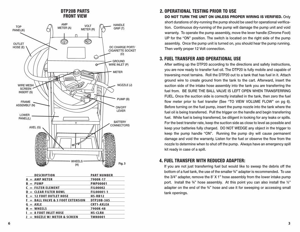
Fig. 3
DTP20B PARTSFRONT VIEW
NOZZLE (J)WIRE MESH SCREEN
INSERT (S)
AMPMETER (A)
HANDLE GRIP (T)
VOLTMETER (R)
METER
GROUNDWIRE INLET (P)
DC CHARGE PORT/ CIGARETTE SOCKET
(O)
PUMP (B)
ON/OFF LEVER
BATTERY CONNECTORS
OUTLETHOSE (E)
TOP PANEL(K)
LOWER PANEL(L)
AXEL (G)
WHEELS(H)
DESCRIPTION PART NUMBER A = AMP METER 7900K-17 B = PUMP PMP00001 C = FILTER ELEMENT FIL00002 D = CLEAR FILTER BOWL FIL00001-1 E = 12 FOOT OUTLET HOSE HS-RB12 F = BALL VALVE & 3 FOOT EXTENSION DTP20B-3AS G = AXLE CRT1-AXLEA H = WHEELS 7900K-48 I = 8 FOOT INLET HOSE HS-CLR8 J = NOZZLE W/ METER & SCREEN TMN0001
FRAME ASSEMBLY (N)
4. FUEL TRANSFER WITH REDUCED ADAPTER:If you are not just transferring fuel but would like to sweep the debris off the bottom of a fuel tank, the use of the smaller ¾” adapter is recommended. To use the 3/4” adapter, remove the 8’ X 1” hose assembly from the lower intake pump port. Install the ¾” hose assembly. At this point you can also install the ½” adapter on the end of the ¾” hose and use it for sweeping or accessing small tank openings.
4 5
5. METERSThe Amp Meter displays the amount of current the pump is drawing from the batteries. Several factors affect the amount of current drawn from the batteries, such as length of hose, temperature, fluid viscosity, and the condition of termi-nal connections. The pump typically draws between 20-30 amps under normal operating conditions. Look for a positive indication on AMP and VOLT meter to confirm proper battery connections.
The Voltage Meter indicates proper battery connections and current condition of the batteries at standstill and under load. This pump should not be run when the battery’s voltage reads less than 11.0 volts. A fully charged battery should read approximately 12.4 volts DC before the load is applied.
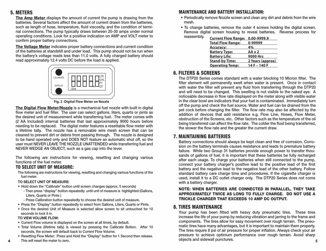
CALIBRATE LTRGALPTQT
LBatDISPLAY
Fig. 2 -Digital Flow Meter on Nozzle
The Digital Flow Meter/Nozzle is a mechanical fuel nozzle with built in digital flow meter and fuel filter. The user can select gallons, liters, quarts or pints as the desired unit of measurement while transferring fuel. The meter comes with (2 AA Included) internal batteries that last approximately 9000 hours before needing to be replaced. The digital meter features a resettable flow meter with a lifetime tally. The nozzle has a removable wire mesh screen that can be cleaned to prevent dirt or debris from passing through. The nozzle is designed to be hand operated only and DOES NOT feature an automatic shut off, so the user must NEVER LEAVE THE NOZZLE UNATTENDED while transferring fuel and NEVER WEDGE AN OBJECT, such as a gas cap into the lever.
The following are instructions for viewing, resetting and changing various functions of the fuel meter.TO SELECT UNIT OF MEASURE:
The following are instructions for viewing, resetting and changing various functions of the fuel meter.
TO SELECT UNIT OF MEASURE:• Hold down the “Calibrate” button until screen changes (approx. 5 seconds) - Then press “display” button repeatedly until unit of measure is highlighted (Gallons,
Liters, Quarts or Pints ) - Press Calibration button repeatedly to choose the desired unit of measure.• Press the “Display” button repeatedly to select from Gallons, Liters, Quarts or Pints. • Once the desired Unit of Measure is selected allow screen to sit untouched for 10
seconds to lock it in.TO VIEW VOLUME FLOW:• Current Flow volume is displayed on the screen at all times, by default.• Total Volume (lifetime tally) is viewed by pressing the Calibrate Button. After 10
seconds, the screen will default back to Current Flow Volume.• Resetting Flow Meter: Press and Hold the “Display” button for 1 Second then release.
This will reset the meter to zero.
7. MAINTAINING BATTERIESBattery connections should always be kept clean and free of corrosion. Corro-sion on the battery terminals causes resistance and leads to premature battery failure. While two Group 31 batteries provide enough power to transfer thou-sands of gallons of fuel, it is important that these batteries be fully recharged after each usage. To charge your batteries when still connected to the pump, connect your battery charger’s positive lead to the positive lead of the first battery and the negative lead to the negative lead of the other battery. Follow standard battery care charge time and procedures. If the cigarette charger is used, install it to a DC outlet charger only. The DTP20 Series does not come with a battery charger.
NOTE: WHEN BATTERIES ARE CONNECTED IN PARALLEL, THEY TAKE APPROXIMATELY TWICE AS LONG TO FULLY CHARGE. DO NOT USE A TRICKLE CHARGER THAT EXCEEDS 10 AMP DC OUTPUT.
6. FILTERS & SCREENSThe DTP20 Series comes standard with a water blocking 10 Micron filter. The filter element will permanently swell when water is present. Once in contact with water the filter will prevent any fluid from transferring through the DTP20 and will need to be changed. This swelling is not visible to the naked eye. A noticeable decrease in flow rate displayed on the meter along with visible water in the clear bowl are indicators that your fuel is contaminated. Immediately turn off the pump and check the fuel source. Water and fuel can be drained from the pet cock before changing the filter. The flow rate may also be affected by the addition of devices that add resistance e.g. Flow Line, Hoses, Flow Meter, obstruction of the Screens, etc. Other factors such as the temperature of the oil being transferred can affect the flow rate. The colder the fluid being transferred, the slower the flow rate and the greater the current draw.
8. TIRES MAINTENANCEYour pump has been fitted with heavy duty pneumatic tires. These tires increase the life of your pump by reducing vibration and jarring to the frame and components. The tires allow for easy movement over rough terrain. The pneu-matic tires have many advantages, but it is important to maintain them properly. The tires require 8 psi of air pressure for proper inflation. Always check your air pressure to achieve optimum performance over rough terrain. Avoid sharp objects and sidewall punctures.
Current Flow Range: 0.00-9999.9 Total Flow Range: 0-99999 Accuracy: 4% Battery Type: AA x 2 Battery Life: 9000 Hrs Stand-by Time: 2 Years (approx) Operating Temp: 14 F – 140 F
MAINTENANCE AND BATTERY INSTALLATION:• Periodically remove Nozzle screen and clean any dirt and debris from the wire
mesh.• To change batteries, remove the outer 4 screws holding the digital screen.
Remove digital screen housing to reveal batteries. Reverse process for reassembly.