industrial control - bulletin 825-p modular protection system€¦ · · 2014-12-11bulletin 825-p...
TRANSCRIPT
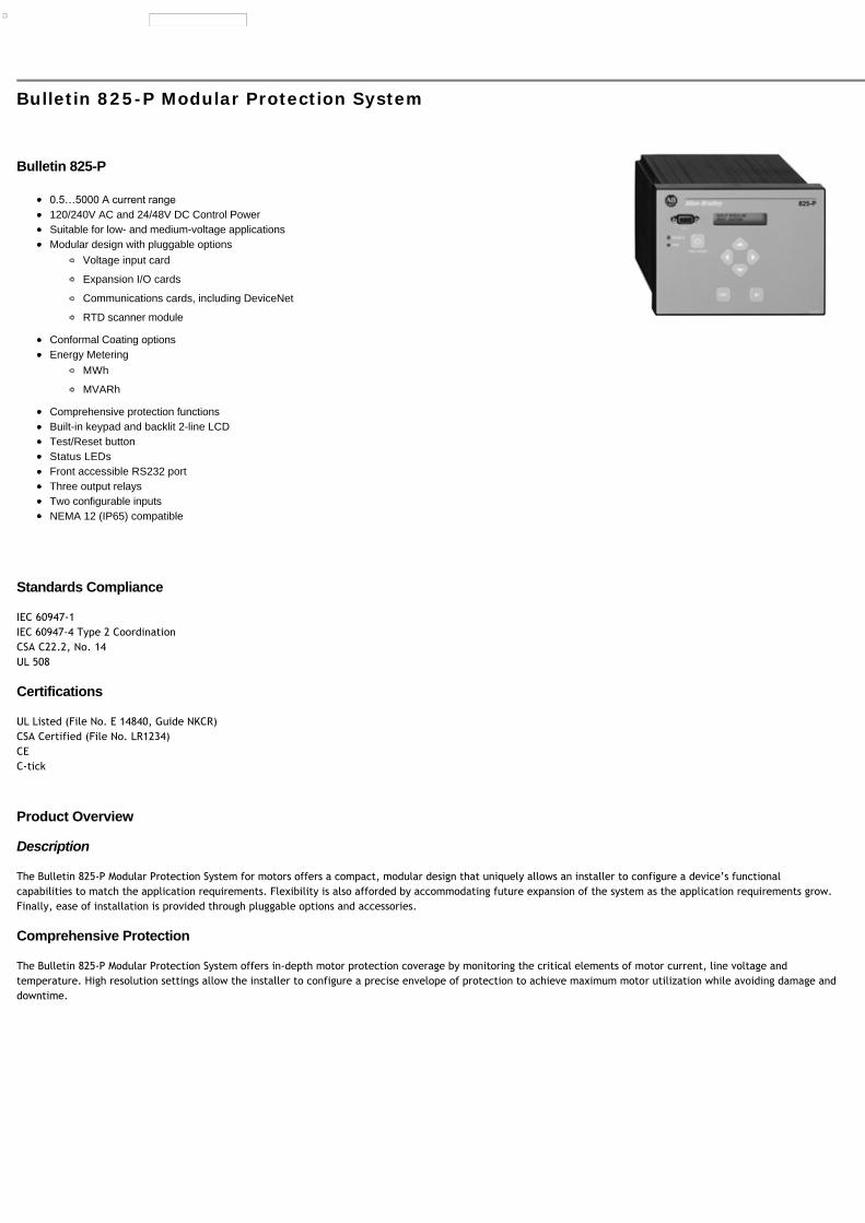
Bulletin 825-P Modular Protection System
Bulletin 825-P
120/240V AC and 24/48V DC Control PowerSuitable for low- and medium-voltage applicationsModular design with pluggable options
Voltage input card
Expansion I/O cards
Communications cards, including DeviceNet
RTD scanner module
Conformal Coating optionsEnergy Metering
MWh
MVARh
Comprehensive protection functionsBuilt-in keypad and backlit 2-line LCDTest/Reset buttonStatus LEDsFront accessible RS232 portThree output relaysTwo configurable inputsNEMA 12 (IP65) compatible
Standards Compliance
IEC 60947-1IEC 60947-4 Type 2 CoordinationCSA C22.2, No. 14UL 508
Certifications
UL Listed (File No. E 14840, Guide NKCR)CSA Certified (File No. LR1234)CEC-tick
Product Overview
Description
The Bulletin 825-P Modular Protection System for motors offers a compact, modular design that uniquely allows an installer to configure a device’s functionalcapabilities to match the application requirements. Flexibility is also afforded by accommodating future expansion of the system as the application requirements grow.Finally, ease of installation is provided through pluggable options and accessories.
Comprehensive Protection
The Bulletin 825-P Modular Protection System offers in-depth motor protection coverage by monitoring the critical elements of motor current, line voltage andtemperature. High resolution settings allow the installer to configure a precise envelope of protection to achieve maximum motor utilization while avoiding damage anddowntime.

ANSII No. Function ANSII No. Function
Current Elements Temperature Elements
51 Thermal Overload 49 PTC Thermistor
46 Current Imbalance/Phase Loss 49 Stator RTD
50G/51G Ground Fault 38 Bearing RTD
37 Undercurrent (Load Loss) — Ambient and Other RTD
48 Overcurrent (Load Jam) Power Elements
50 Short Circuit 37 Underpower
47 Phase Reversal 55/78 Power Factor
81 Frequency — Reactive Power
86 Overload Lockout — —
Voltage Elements Motor Starting Elements
27 Undervoltage 66 Starts/Hour
59 Overvoltage — Stall - Acceleration Time Monitoring
47 Phase Reversal 14 Speed Switch Monitoring
81 Frequency 19 Reduced Voltage Starting
— — 48 Incomplete Start
NOTE: Voltage, power, and energy elements are only available with the installation of the voltage input option card.
Full Function Metering
Current Elements Voltage Elements Power Elements Energy Elements Thermal Elements
Phase Currents Line-Line Voltages Real Power (kW) Real Energy (MWh) % Thermal Capacity Utilization
Average Current Avg. Line-Line Voltage Reactive Power (kVAR) Reactive Energy Forward (MVARh) RTD Values
% Motor Load Line-Neutral Voltages Apparent Power (kVA) Reactive Energy Reverse (MVARh) —
Current Imbalance Avg. Line-Neutral Voltage Power Factor Apparent Energy (MVAh) —
Ground Fault Current Voltage Imbalance — — —
System Frequency System Frequency — — —
NOTE: Voltage and power elements are only available with the installation of the voltage input option card.
Statistical Values
The 825-P Modular Protection System provides the following valuable statistical values of motor operation:
Elapsed time of operation
Stopped time
Percent of time running
Number of starts
Number of emergency starts
Date and time of last trip reset
Historical Data
The 825-P Modular Protection System saves records for the five most recent trip events. Each trip event is summarized with record of the following prior to trip datacapture:
Event day and time
Trip identification
Phase and ground current values

Voltage values
Function Overview
Description Trip Level Setting Range Trip Delay Setting Time Warning Level Setting Range
Motor FLA Ie 0.5…5000 A — —
Locked Rotor Current 2.5…12 x Ie — 50…100% TCU
Locked Rotor Time 1…600 s — —
Short Circuit 4…12 x Ie 0…5.00 s 4…12 x Ie
Ground Fault (Residual) 0.1…1.0 x Ie 0…5.00 s 0.1…1.0 x Ie
Ground Fault (Core balance) 0.01…25 A 0…5.00 s 0.01…25 A
Jam 1.0…6.0 x Ie 0…5.00 s 1.0…6.0 x Ie
Undercurrent 0.1…1.0 x Ie 0…120 s 0.1…1.0 x Ie
Current Imbalance 5…80% 0…240 s 5…80%
Start Monitoring — 0…240 s —
RTD Temp 0…250 °C — 0…250 °C
Phase Reversal Disable, Enable — —
Undervoltage 0.60…1.00 x Vnom 0…120 s 0.60…1.00 x Vnom
Overvoltage 1.00…1.20 x Vnom 0…120 s 1.00…1.20 x Vnom
Underpower 1…25000 kW 0…240 s 1…25000 kW
Power Factor 0.05…0.99 0…240 s 0.05…0.99
VAR 1…25000 kVAR 0…240 s 1…25000 kVAR
Frequency 45…55/55…65 Hz 0…240 s 45…55/55…65 Hz
Start Inhibit (Starts/hour) 1…15 — —
Speed Switch — 0…240 s —

Description Cat. No.
Basic UnitNote: The minimum requirements for a complete basic system are one basic unit and one converter module.
120…240V AC/DC 825-PD⋆
24…48V DC 825-PZ⋆
Converter Module 0.5…2.5 A 825-MCM2
1.0…5.0 825-MCM5
181…520 A 825-MCM20
30…180 A 825-MCM180
160…420 825-MCM420
160…630 A 825-MCM630N
Core Balance Ground Fault Sensor 100:1 825-CBCT
RTD Scanner Module12 RTD input channels with individual programming for 10 copper, 100 nickel, 120 nickel, or 100 platinum. Fiberoptic connection to Basic Unit. Class I, Division 2, Group T48.
120 / 240V AC 825-PR12D
Voltage Input CardMonitoring of VA, VB, VC, and VN
300V AC Line toNeutral Max.
825-PVS⋆
Expansion I/O Card(3) Inputs(4) Output relays(1) 4…20 mA analog output
120V AC Rated Inputs 825-PIOD⋆
24V DC Rated Inputs 825-PIOR⋆
DeviceNet Communication CardDeviceLogix technology, Node address selection switches, ODVA conformance tested.
— 825-PDN⋆
Modbus RTU Communication Card — 825-PMB⋆
MPS Explorer Software § Windows-basedConfiguration Tool
Operation Instructions ‡ Quick Start Guide 825-QS001*
Basic Unit User Manual 825-UM004*
DeviceNet Card 825-UM005*
⋆ Factory modification available. For conformal coating add CC to the cat. no. Example: Cat. No. 825-PZ becomes Cat. No. 825-PZ-CC.
§ Please contact your local Rockwell Automation sales office or Allen-Bradley distributor.
‡ Detailed operation instructions ship separately from the product. Please contact your local Rockwell Automation sales office or Allen-Bradley distributor to obtain printed copies.
NOTE: A no-charge download can be found at www.rockwellautomation.com/support/firmware.html.

Description Cat. No.
Bus Bars for 825-MCM180Three-piece set includes terminals and screws
M8 connectionsSet of three4 x 16 x 102 mm (1/8 x 5/8 x 4-1/64 in.) (125 A max.)Universally applicableWeight: 230 g
825-MVM
M8 connectionsSet of three4 x 20 x 117 mm (1/8 x 25/32 x 4-39/64 in.) (180 A max.)Universally applicable
825-MVM2
M6 lower connectionsSet of threeFor mounting on Bul. 100-D105 and 100-D110 contactors with conventionalcoil
825-MVS
M8 lower connectionsSet of threeFor mounting on Bul. 100-D140, 100-D180 conventional and Bul. 100-D105E…100-D180E contactors with electronic coil
825-MVS2
Terminal ShieldsSet of two
Protection class IP10 per IEC 60529 and DIN 40 050
For direct-on-line, reversing, two-speed, and wye-delta/star-delta assemblies
100-D115 100-DTS110
100-D115…100-D180, 193-FE 100-DTS180
100-D210...100-D420, 193-FE 100-DTS420
Terminal LugsSet of two
Protection class IP2X per IEC 60529 and DIN 40 050
100-D115 100-DTB110
100-D115, 100-D140, 100-D180, 100-D115E…D180E, 193-EC_F, 193-EE_F 100-DTB180
100-D210...100-D420, 193-EC_G, 193-EF2C, 193-EE_G 100-DTB420
Thermal Utilization Meter For display of percent thermal capacity utilizedRequires the use of an Expansion I/O Card
825-MTUM
DeviceNet Configuration TerminalUsed to interface with objects on a DeviceNet network. Includes1 m communications cable (193-CB1).
193-EDN,193-EC (all), 592-EC (all); 280/281/283/284 ArmorStart,825-P
193-DNCT
1 meter communication cable, color-coded bare leads 193-DNCT 193-CB1
1 meter communication cable, microconnector (male) 193-DNCT 193-CM1
Panel Mount Adapter/Door Mount Bezel Kit 193-DNCT 193-DNCT-BZ1
EtherNet/IP Communications AuxiliaryDeviceNet to EtherNet/IP linking device
Single port 193-EC_C (all), 592-EC_C (all) 193-DNENCAT
Dual port 193-EC_C (all), 592-EC_C (all) 193-DNENCATR
— Connection Cable (Replacement) Cat. No. 150-SM2 to Bul. 825-MCM Connection 825-MCA
Electrical Ratings
Main Circuits
Rated Operating Voltage Ue 825-MCM2825-MCM5
825-MCM20 825-MCM180825-MCM420825-MCM630N
IECCSA/UL
400V AC240V AC
690V AC600V AC
1000V AC600V AC
Rated Impulse Strength Uimp 2.5 kV 6 kV 8 kV
Operating Current Range (A) 825-MCM2 825-MCM5 825-MCM20 825-MCM180 825-MCM420 825-MCM630N
0.5…2.5 1…5 2.5…20 20…180 160…420 160…630
Rated Continuous Thermal Current (A) 3 6 24 216 504 756
Rated Saturation Current (A) 30 60 240 1350 3400 4600
Rated Frequency 50/60 Hz ±3 Hz
Voltage Input Option Card
Rated Operating Voltage Ue 250V AC Max
Operating Range 0.8…1.1 Ue
Rated Continuous Voltage 300V AC
Rated Insulation Voltage Ui 300V AC
Rated Impulse Strength Uimp 4kV

Rated Frequency 50/60 Hz ±5 Hz
Control Circuits
Supply
Rated Supply Voltage Us 110…240V AC, 110…250V DC 24…48V DC
Operating Range 0.8…1.1 Ue 0.8…1.1 Ue
Rated Frequency (V AC) 50/60 Hz ±5 Hz —
Max. Power Consumption 40VA (AC) / 15W (DC) 15 W
Output Relays
Type of Contacts Trip Form C SPDT
Aux1…Aux6 Form A SPST — N.O.
Rated Insulation Voltage Ui 300V AC
Rated Operating Voltage Ue 240V AC
Rated Impulse Strength Uimp 4kV
Rated Thermal Current Ithe 5 A
Rated Operating Current Ie 120V AC 3 A
240V AC 1.5 A
Contact Rating Designation B300
Utilization Category AC15
Contact Reliability 5 mA @ 17V
Inputs
Rated Operating Voltage Ue IN1 and IN2 IN3, IN4, and IN5
24V AC/DC 120V AC/DC (825-PIOD), 24V AC/DC (825-PIOR)
Operating Range 0.8…1.1 Ue
Rated Insulation Voltage Ui 300V AC
Rated Impulse Strength Uimp 4kV
Rated Frequency (V AC) 50/60 Hz ±5 Hz
On-State Voltage 15V 79V
On-State Current (turn-on) 2 mA 2 mA
Steady-State Current 15 mA 15 mA
Off-State Voltage 5V 20V
Off-State Current 0.5 mA 1 mA
Transition Voltage 5…15V 20…79V
PTC Thermistor Input
Type of Control Unit Mark A
Max. No. of Sensors in Series 6
Max. Cold Resistance of PTC Sensor Chain 1500
Trip Resistance 3400 ± 150
Reset Resistance 1500…1650
Short-Circuit Trip Resistance 25 ± 10
Mechanical Ratings
Environmental
Ambient Temperature Storage -40…+85 °C (-40…+185 °F)
Operation (open) -20…+60 °C (-4…+140 °F)
Humidity (Operating) 5…95%, non-condensing
Max. Altitude 2000 m
Vibration (Per IEC 68-2-6) 3 G
Shock (per IEC 68-2-27) 30 G
Control Terminals
Terminal Screw M3
Cross Section (1 wire, stranded/solid) 0.14…2.5 mm2 (#20…12 AWG)
Terminal Screw Torque 0.79 N•m (7 lb-in)
Electromagnetic Compatibility
Electrostatic Discharge Immunity Test Level 8 kV Air Discharge, 6 kV Contact Discharge
Performance Criteria 1 § ‡
RF Immunity Test Level 10V/m
Performance Criteria 1 § ‡
Electrical Fast Transient/Burst immunity Test Level 4 kV (Power), 2 kV (Control and Comms)
Performance Criteria 1 § ‡
Surge Immunity Test Level 2 kV L-E, 1 kV L-L
Performance Criteria 1 § ‡
Radiated Emissions Class A
Conducted Emissions Class A
§ Performance Criteria 1 requires the DUT to experience no degradation or loss of performance.
‡ Environment 2.
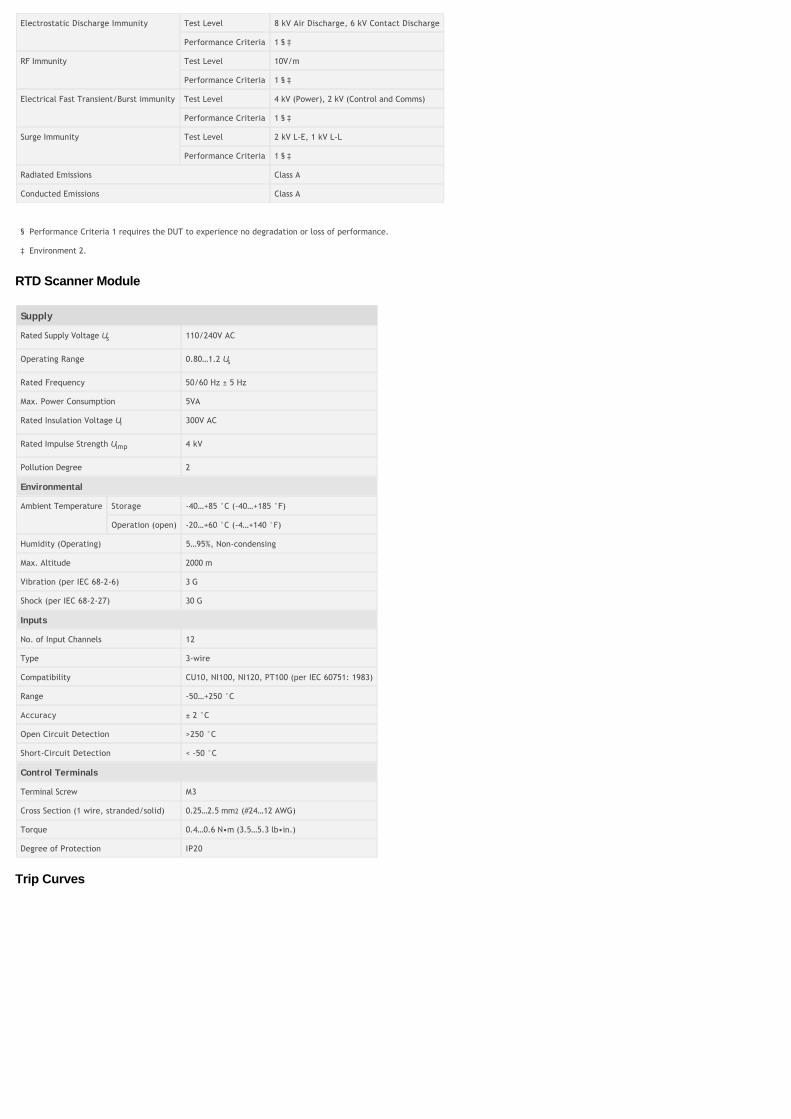
RTD Scanner Module
Supply
Rated Supply Voltage Us 110/240V AC
Operating Range 0.80…1.2 Us
Rated Frequency 50/60 Hz ± 5 Hz
Max. Power Consumption 5VA
Rated Insulation Voltage Ui 300V AC
Rated Impulse Strength Uimp 4 kV
Pollution Degree 2
Environmental
Ambient Temperature Storage -40…+85 °C (-40…+185 °F)
Operation (open) -20…+60 °C (-4…+140 °F)
Humidity (Operating) 5…95%, Non-condensing
Max. Altitude 2000 m
Vibration (per IEC 68-2-6) 3 G
Shock (per IEC 68-2-27) 30 G
Inputs
No. of Input Channels 12
Type 3-wire
Compatibility CU10, NI100, NI120, PT100 (per IEC 60751: 1983)
Range -50…+250 °C
Accuracy ± 2 °C
Open Circuit Detection >250 °C
Short-Circuit Detection < -50 °C
Control Terminals
Terminal Screw M3
Cross Section (1 wire, stranded/solid) 0.25…2.5 mm2 (#24…12 AWG)
Torque 0.4…0.6 N•m (3.5…5.3 lb•in.)
Degree of Protection IP20
Trip Curves

⋆⋆
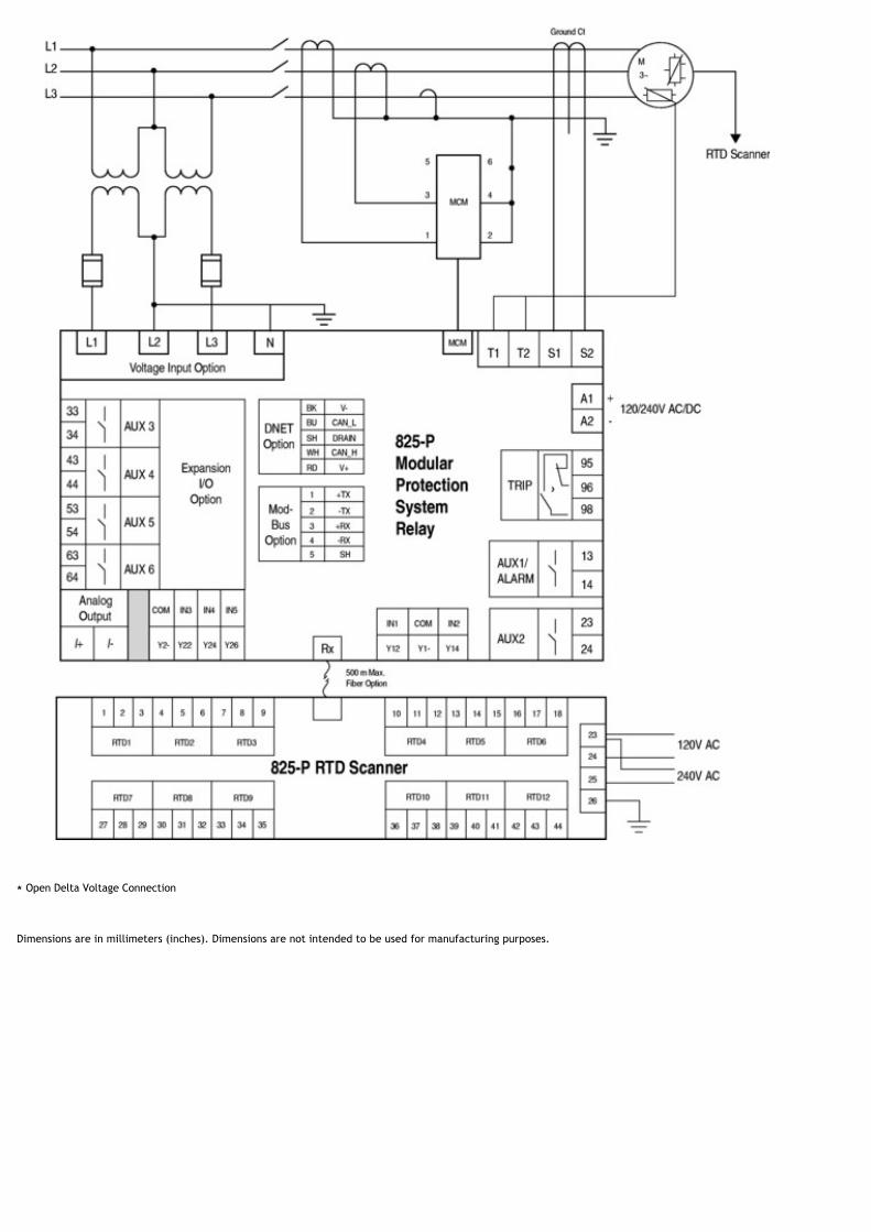
⋆ Open Delta Voltage Connection
Dimensions are in millimeters (inches). Dimensions are not intended to be used for manufacturing purposes.

Core Balance Current Transformer
Bulletin 825-MCM Converter Module
Cat. No. 825-MCM2...825-MCM180Cat. No. 825-MCM420

Cat. No. 825-MCM630N
Dimensions
Cat. No. a b c c1 ø d d1 d2 d3 ø e ø e1 e2 b1 b2
825-MCM2,-MCM5,-MCM20
120 85 102 66 5.3 5.3 100 55 2 x 2.5mm2
— 38.5
825-MCM180 120 102 72 5.3 5.3 100 55 ∆ ∆ 38.5 75 § / 100/118
825-MCM420 155 145 156 118 6.3 6.3 135 88 11 M10 48
825-MCM630N 155 145 177 118 6.3 6.3 135 88 11 M10 48
For snapping on to DIN Rail (EN 50 022-35 x 15 or 35 x 7.5).‡ Cat. No. 825-MCM180; with bus bar or max. ø 19 mm aperture for looping the conductors.§ With Cat. No. 825-MVM.
Cat. No. 825-MVM2∆ See below for bus bars for Cat. No. 825-MCM180.
Bus Bars
Terminal Dimensions
Cat. No. Bottom Top
825-MVM M8 M8
RTD Scanner

Rockwell Automation, Inc. All Rights Reserved.