industrial components & devices line card catalog - panasonic · industrial components &...
TRANSCRIPT

Industrial Components & Devices
Line Card Catalog
Wireless ConnectivityInductors ConnectorsRelays CapacitorsResistorsSemiconductorsStorage MediaCircuit ProtectionSensorsElectromechanicalThermal Management
800-344-2112 | na.industrial.panasonic.com | [email protected]

Always Receive The Latest From Panasonic!
Join The Conversation
linkd.in/1oJJw9s
plus.ly/PIDSA
www.facebook.com/panasonicindustrial
na.industrial.panasonic.com/blog
twitter.com/panasonicelec
youtube.com/panasonicindustrial
Subscribe now by visiting pages.na.industrial.panasonic.com/subscribe.
Subscribe to be the first to receive exclusive engineering news, information and design in tools from Panasonic.
Receive information on the newest products, technologies and applications Panasonic has to offer right when they become available!
Joining the Panasonic Community puts members ahead of the curve for designing in the most current electronic technologies on the market today.

Design and specifications are subject to change without notice. Please review technical specifications before purchase. For any questions regarding these products, please visit na.industrial.panasonic.com.
33
Many products sold by Fortune 500 companies use Panasonic technology, and we are proud to provide manufacturers with the performance, quality, and reliability that are synonymous with the Panasonic brand.
Panasonic brings strategic innovations to our customers’ product development process. We provide the technology and engineering resources to enable manufacturers to plan and build world-class solutions to meet their customer needs.
Engineering and manufacturing form the core of our company’s strength, infusing our entire product line, from the smallest component to the most complex devices.
Our broad product portfolio draws on a level of proprietary technology rarely found anywhere else in the world, giving Panasonic added value that competitors find difficult to achieve.
Our technology is deeply embedded within our customers’ products, and our measure of success is the confidence and trust shown in our technology when it becomes the core of our customers’ products.
At Panasonic, we’re driven to make what matters most, better. Just another way we’re engineering a better world for you.
Industrial Components & Devices
Line Card Catalog

4
Power Choke Coils 29-31EMI Filters; Chip Choke Coils 31
INDUCTORS
Light Touch Switches 13-14Detector Switches 15Snap Action Switches 16-17Interlock Switches; Operation Switches 18 Encoders; Potentiometers 19
SENSORSELECTROMECHANICAL
Chip Resistors 23Current Sensing Resistors 24High Precision Chip Resistors; Anti-Sulfurated Chip Resistors 25Wide Terminal Chip Resistors; Axial Leaded Resistors 26Resistor Arrays & Networks 27
RESISTORS
RF Modules: Bluetooth®; Mesh Networking (802.15.4); ISM; WiFi 21
WIRELESS CONNECTIVITY
CAPACITORSOS-CON™ Polymer Aluminum; SP-Cap™ Polymer Aluminum 7POSCAP™ Polymer Aluminum; Gold Cap Electric Double Layer Radial Lead 8Aluminum Electrolytic, Leaded 9Aluminum Electrolytic, Surface Mount 10Film, Leaded; Film, Surface Mount Chip 11
Power 33-35PhotoMOS® 36-37PhotoIC Coupler; Solid State 38Automotive 39Microwave Devices 40Signal 41
RELAYS
55
Passive Infrared 49Infrared Array: Grid-EYE®; Air Pressure 50
SENSORS
Diodes; ASSP 53MOSFETs 54
SEMICONDUCTORS
Thermistors; ZNR Surge Absorbers; Varistors 57EMI Filters 58Fuse Resistors; ESD Suppressors 59
ELECTROMECHANICALCIRCUIT PROTECTION
Pyrolytic Graphite Sheet (PGS) 61-63Soft PGS; Semi-Sealing Material (SSM), Graphite-PAD 64NASBIS Insulating Sheet 65
THERMAL MANAGEMENTTM
Narrow Pitch Board to FPC; Narrow Pitch Board to Board 43-44FPC Connectors 44Active Optical Connectors; Stacking Connectors for High Current 45
CONNECTORS
SD Cards 47
STORAGE MEDIAM
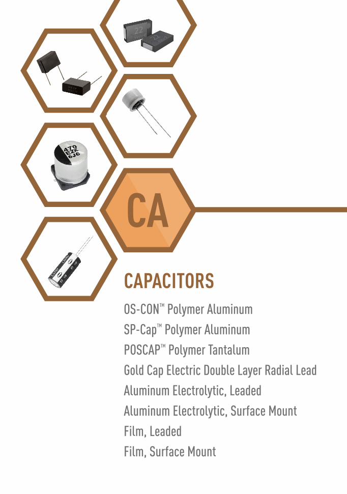
OS-CON™ Polymer AluminumSP-Cap™ Polymer AluminumPOSCAP™ Polymer TantalumGold Cap Electric Double Layer Radial LeadAluminum Electrolytic, LeadedAluminum Electrolytic, Surface MountFilm, LeadedFilm, Surface Mount
CAPACITORS
7
SeriesOperating
Temperature(Working Voltage)
Capacitance Features
SP-C
AP: P
olym
er A
lum
inum
- Su
rface
Mou
nt
Gene
ral P
urpo
se
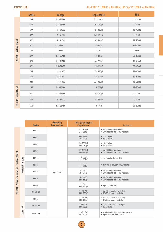
EEF-CD
-40 ~ +105ºC
(2 ~ 16 VDC)2.2 ~ 220 μF
• Low ESR, high ripple current• 1.8 mm height, ESR 18 mΩ maximum
EEF-CS (4 ~35 VDC)68 ~ 120 μF
• 1.2mm height• Low ESR 15mΩ
EEF-CT (4 ~ 35 VDC)100 ~ 180 μF
• 1.5mm height• Low ESR 15mΩ
EEF-CX (2 ~ 35 VDC)100 ~ 560 μF
• Low ESR, high ripple current• 1.9 mm height, ESR 15 mΩ maximum
EEF-SR (2 ~ 6.3) 68 ~ 220 μF • 1 mm max height; Low ESR
EEF-LR (2 ~ 6.3) 68 ~ 220 μF • 1mm max height; Low ESR, 3 terminals
EEF-UD (2 ~ 8 VDC)68 ~ 470 μF
• Low ESR, high ripple current• 2.8 mm height, ESR 15 mΩ maximum
EEF-UE (2 ~ 8 VDC)100 ~ 560 μF
• Low ESR, high ripple current• 4.2 mm height, ESR 12 mΩ maximum
EEF-GX (2 VDC)330 ~ 470 μF • Super low ESR 3mΩ
EEF-LS, -LT (2 ~ 2.5 VDC)180 ~ 330 μF
• Low ESL by structure of SP-Cap • 50% ESL of current products
EEF-LX (2 ~ 2.5 VDC)330 ~ 560 μF
• Low ESL by structure of SP-Cap • 50% ESL of current products
Low
ESR EEF-SS, -ST (2 ~ 2.5 VDC)
180 ~ 330 μF• 1.2mm (SS), 1.5mm (ST) height• Low ESR 6mΩ
EEF-SL, -SX (2 ~ 6.3 VDC)56 ~ 560 μF
• Excellent noise absorbent characteristics• Super low ESR (4.5mΩ - 9mΩ)
Series Voltage Capacitance ESROS
-CON
: Sur
face
Mou
ntSVP 2.5 – 25 VDC 3.3 - 1500 μF 12 - 260 mΩ
SVPC 2.5 – 16 VDC 39 - 2700 μF 9 - 35 mΩ
SVPF 16 – 50 VDC 10 - 1000 μF 12 - 40 mΩ
SVPE 2 – 16 VDC 150 - 1200 μF 8 - 20 mΩ
SVPA 4 – 20 VDC 47 - 680 μF 19 - 28 mΩ
SVPD 25 – 30 VDC 10 - 82 μF 28 - 65 mΩ
SVPG 16 VDC 47 μF 8 mΩ
SVPS 6.3 – 25 VDC 10 - 330 μF 20 - 60 mΩ
SVQP 6.3 – 10 VDC 56 - 220 μF 10 - 45 mΩ
SVPB 2.5 - 20 VDC 15 - 120 uF 35 - 45 mΩ
SVF 16 - 50 VDC 27 - 1000 μF 12 - 40 mΩ
SVPK 25 - 50 VDC 10 - 470 μF 14 - 80 mΩ
SEF 16 - 35 VDC 22 - 1000 μF 12 - 35 mΩ
OS-
CON:
Rad
ial L
ead SEP 2.5 – 25 VDC 6.8-1500 μF 12 - 80 mΩ
SEPC 2.5 – 16 VDC 100-2700 μF 5 - 24 mΩ
SEPF 16 – 35 VDC 22-1000 μF 12-35 mΩ
SEQP 6.3 – 32 VDC 15-330 μF 20 - 80 mΩ
CAPACITORS
CAPACITORS OS-CON™ POLYMER ALUMINUM; SP-Cap™ POLYMER ALUMINUM

POLYMER ALUMINUM; ELECTRIC DOUBLE LAYER CAPACITORS
8
SeriesOperating
Temperature(Working Voltage)
Capacitance Features
Gold
Cap
: Ele
ctric
Dou
ble L
ayer
Rad
ial L
ead
EEC-S0HDEEC-S5R5 -25 ~ +70°C (5.5 VDC) 0.22 ~ 0.33F
(5.5 VDC) 0.47 ~ 1.5F• General purpose, 1,000 hours at 70°C• µA range IC memory back-up
EEC-S0HDEEC-S5R5 -40 ~ +70°C (5.5 VDC) 0.22 ~ 0.33F
(5.5 VDC) 0.47 ~ 1.5F • Can handle as low as -40°C
EEC-SE0H -25 ~ +70°C (5.5 VDC) 0.22F • 1,000 hours at 70°C• Lead taping for auto insertion
EEC-SE0HN -40 ~ +70°C (5.5 VDC) 0.22F • Can handle as low as -40°C
EEC-SG -25 ~ +70°C (5.5 VDC) 0.47 ~ 1.5F • General Purpose, 70°C• Tabbed Leads”
EEC-SGN -40 ~ +70°C (5.5 VDC) 0.47 ~ 1.5F• General Purpose, 70°C• Tabbed Leads• Can handle as low as -40°C
EEC-NF 25 ~ +70°C (5.5 VDC) 0.22 ~ 1.5F • General Purpose, 70°C• Flat Body
EEC-NFN 40 ~ +70°C (5.5 VDC) 0.22 ~ 1.5F•General Purpose, 70°C• Flat Body• Can handle as low as -40°C
EEC-RGEEC-RF -25 ~ +85°C (3.6 VDC) 0.22 ~ 1.5F
(5.5 VDC) 0.10 ~ 1.0F
• 2,000 hours at 85°C, general purpose• High Reliability• Backup for mA-A range
EEC-RGNEEC-RFN -40 ~ +85°C (3.6 VDC) 0.22 ~ 1.5F
(5.5 VDC) 0.10 ~ 1.0F • Can handle as low as -40°C
EEC-HW0D -25 ~ +70°C-25 ~ +60°C
(2.3 VDC) 22 ~ 50F(2.1 VDC) 70F
• Large capacitance• Backup for mA - A range
EEC-HZ0D -25 ~ +60°C (2.5 VDC) 3.3~10F • Large Capacitance• Lower ESR than HW
EEC-HL -40 ~ +65°C (2.7 VDC) 50 and 100 F • Can handle discharge current in the 10 to 15Amp range.• 10 amps for the 50°F part. 15 amps for the 100°F part”
Series Voltage Capacitance ESRPO
SCAP
: Pol
ymer
Alu
min
um -
Surfa
ce M
ount
TPE 2 - 10 VDC 47 - 1500 μF 7 - 35 mΩ
TQC 16 -3 5 VDC 3.9 - 150 μF 40 - 150 mΩ
TQS 16 - 35 VDC 6.8 - 3.3 μF 70 - 150 mΩ
TPF 2 - 10 VDC 150 - 1000 μF 5 - 15 mΩ
TPSF 2 VDC 270 μF 6 - 9 mΩ
TPB 4 - 10 VDC 33 - 470 μF 35 - 70 mΩ
TPC 6.3 - 12.5 VDC 10 - 330 μF 40 - 80 mΩ
TPG 2.5 - 12.5 VDC 33 - 220 μF 30 - 70 mΩ
TPU 2.5 - 10 VDC 4.7 - 150 μF 100 - 300 mΩ
TA 2.5 - 6.3 VDC 47 - 220 μF 9 - 70 mΩ
TH 2.5 - 10 VDC 68 - 470 μF 15 - 40 mΩ
TPH 6.3 VDC 47 μF 150 mΩ

CAPACITORS ALUMINUM ELECTROLYTIC, LEADED
9
SeriesOperating
Temperature(Working Voltage)
Capacitance FeaturesAl
umin
um El
ectro
lytic
, Lea
ded
Gene
ral P
urpo
se
85°C ECA-__M -40 ~ +85°C
(-25°C: 160~450 VDC)(6.3 ~ 450 VDC)0.1 ~ 22,000 μF
• General purpose, 2000 hours at 85°C• Compact size
105°
C
ECA-__HG -55 ~ +105°C(-25°C: 160~450 VDC)
(6.3 ~ 450 VDC)0.1 ~ 22,000 μF
• Long life: 1,000~2,000 hours at 105°C• Compact size
EEA-GA -55 ~ +105°C (10 ~ 50 VDC)0.1 ~ 220 μF
• Long life: 1000 hours at 105°C• 7mm height
EEU-HD -55 ~ +105°C (10 ~ 50 VDC)0.1 ~ 22000 μF
• Long life: 1000~2000 hours at 105°C• Case Size : 5mm x 11mm to 18mm x 35.5mm
Min
iatu
re ECE-A__KA -40 ~ +85°C (4 ~ 50 VDC)0.1 ~ 470 μF
• General purpose, 1,000 hours at 85°C• 7 mm height
ECE-A__KK/KS -40 ~ +85°C (4 ~ 50 VDC)0.1 ~ 330 μF
• General purpose, 1000 hours at 85°C• 5 mm height
Bi-P
olar
ECE-A__N___U/X -40 ~ +85ºC (6.3 ~ 50 VDC)0.47 ~ 6,800 μF
• 2,000 hours at 85ºC• Bi-Polar general purpose
Long
Life
High
Vol
tage
EEU-EB -40 ~ +105°C(-25°C: 160~450 VDC)
(10 ~ 450 VDC)0.47 ~ 3,300 μF
• 5,000~10,000 hours at 105°C• Very long life
EEU-ED -25 ~ +105°C (160 ~ 450 VDC)10 ~ 330 μF
• Very long life 8,000~10,000 hours at 105°C• High Ripple Current
EEU-EE -25 ~ +105°C (160 ~ 450 VDC)10 ~ 330 μF
• Very long life 8,000~10,000 hours at 105°C• High Ripple Current at high frequency
Low
Impe
danc
e
EEA/U-FC -55 ~ +105°C (6.3 ~ 100 VDC)1.0 ~ 15,000 μF
• 1,000~5,000 hours at 105°C• Low impedance, miniature
EEU-FM -40 ~ +105ºC (6.3 ~ 50 VDC)22 ~ 6,800 μF
• Long life, 2,000~7,000 hours at 105ºC• Low ESR, approximately half of FC
EEU-FR -40 ~ +105°C (6.3 ~ 63 VDC)18 ~ 8,200 μF
• Ultra Low ESR: 12mΩ (20°C/100kHz) • 5000 hours (case sizes 5 and 6mm Ø) ~10,000 hours at 105°C
125º
C - 1
35ºC EEU-TA -40 ~ +125°C (10 ~ 63 VDC)
1 ~ 4,700 μF• 2,000 hours at 125°C• Automotive applications
EEU-TP -40 ~ +135°C (25 ~ 35 VDC)100 ~ 5,100 μF
• Low ESR: 16mΩ (20°C/100kHz)• Long Life: 125°C 2000 to 5000 hours
(135° 1000 hours to 2000 hours)
ALUMINUM ELECTROLYTIC, SURFACE MOUNT CAPACITORS
10
SeriesOperating
Temperature(Working Voltage)
Capacitance Features
Surfa
ce M
ount
Alu
min
um El
ectro
lytic
Gene
ral
Purp
ose
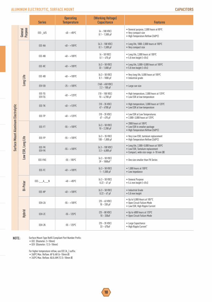
EEE-_A/S -40 ~ +85ºC (4 ~ 100 VDC)0.1 ~ 1,500 μF
• General purpose, 2,000 hours at 85ºC• Very compact size• High Temperature Reflow (260ºC)
Long
Life
EEE-HA -40 ~ +105ºC (6.3 ~ 100 VDC)0.1 ~ 1,500 μF
• Long life, 1000~2,000 hours at 105ºC• Very compact size
EEE-HB -40 ~ +105ºC (4 ~ 50 VDC)0.1 ~ 470 μF
• Long life, 2,000 hours at 105ºC• 5.8 mm height (< Ø 6)
EEE-HC -40 ~ +105ºC (6.3 ~ 50 VDC)33 ~ 1,000 μF
• Long life, 3,000~5,000 hours at 105ºC• 5.8 mm height (< Ø 6)
EEE-HD -40 ~ +105ºC (6.3 ~ 50 VDC)0.1 ~ 1000 μF
• Very long life, 5,000 hours at 105ºC• Industrial grade
EEV-EB -25 ~ +105ºC (160 ~ 450 VDC)2.2 ~ 100 μF • Large can size
EEE-TGEEV-TG -40 ~ +125ºC (10 ~ 100 VDC)
10 ~ 4,700 μF• High temperature, 2,000 hours at 125ºC• Low ESR at low temperature
EEE-TK -40 ~ +125ºC (10 ~ 35 VDC)47 ~ 4700 μF
• High temperature, 3,000 hours at 125ºC• Low ESR at low temperature
EEE-TP -40 ~ +125ºC (10 ~ 35 VDC)47 ~ 470 μF
• Low ESR at Low Temperatures• 2,000~3,000 hours at 125ºC
Low
ESR,
Long
Life
EEE-FT -55 ~ +105ºC (6.3 ~ 50 VDC)10 ~ 2,200 μF
• 2000 hours at 105ºC• Low ESR in smaller package• High Temperature Reflow (260ºC)
EEE-FP -55 ~ +105ºC (6.3 ~ 35 VDC)100 ~ 1,800 μF
• Very Low ESR, tantalum replacement• High Temperature Reflow (260ºC)
EEE-FKEEV-FK -55 ~ +105ºC (6.3 ~ 100 VDC)
3.3 ~ 6,800 μF
• Long life, 2,000~5,000 hours at 105ºC• Low ESR, Tantalum replacement• Compact, wide size range: 4~18 mm (Ø)
EEE-FKS -55 ~ 105ºC (6.3 ~ 50 VDC)39 ~ 1800uF” • One size smaller than FK Series
EEE-FC -40 ~ +105ºC (6.3 ~ 50 VDC)1 ~ 1,500 μF
• 1,000 hours at 105ºC• Low impedance
Bi-P
olar EEE-___A___N -40 ~ +85ºC (6.3 ~ 50 VDC)
0.22 ~ 47 μF• General Purpose• 5.4 mm height (< Ø 6)
EEE-HP -40 ~ +105ºC (6.3 ~ 50 VDC)0.22 ~ 47 μF
• Industrial Grade• 5.8 mm height
Hybr
id
EEH-ZA -55 ~ +105ºC (25 ~ 63 VDC)10 ~ 330 μF
• Up to 5,000 Hours at 105°C• Open Circuit Failure Mode• Low ESR, High Ripple Current
EEH-ZC -55 ~ 125ºC (25 ~ 80 VDC)10 ~ 330uF
• Up to 4000 hours at 125ºC• Open Circuit Failure Mode
EEH-ZK -55 ~ 125ºC (25 ~ 35 VDC)33 ~ 470uF
• Large Capacitance• High Ripple Current”
NOTE: Surface Mount Type RoHS Compliant Part Number Prefix:• EEE (Diameter: 3~10mm)• EEV (Diameter: 12.5~18mm)
For higher temperature reflow, use EEE (A_) suffix:• 260ºC Max. Reflow: AP & AR (4~10mm Ø)• 245ºC Max. Reflow: AQ & AM (12.5~18mm Ø)

11
CAPACITORS FILM, LEADED; FILM, SURFACE MOUNT CHIP
SeriesOperating
Temp. Ratings Features ApplicationsM
etal
lized
Film
, Lea
ded
Plas
ticECW-FE -40 ~ +105ºC 0.1 ~ 4.7 µF
450 and 630VDC • Boxed construction• Active Filter Circuits• High Frequency• High Current Circuits
Poly
este
r
ECQ-E(H) -40 ~ +105ºC 0.1 ~ 2.2 µF 450 VDC • Smaller Size • Active filtering circuit
ECQ-E(F) -40 ~ +85ºC 0.001 ~ 10 µF100 ~ 1250 VDC
• Wide capacitance range• Compact size • General purpose applications
ECQ-E(B) -40 ~ +85ºC 0.01 ~ 4.7 µF 250 VDC • Wide capacitance range• Miniaturized • General purpose applications
Poly
prop
ylen
e
ECW-F(L) -40 ~ +105ºC 0.022 ~ 2.4 µF, 400 VDC0.01 ~ 1.3 µF, 630 VDC
• Low Dissipation Factor• High Voltage
• High Frequency• High Current Circuits
ECW-F(B) -40 ~ +105ºC 0.022 ~ 0.47 µF 400 VDC • Low Dissipation Factor • High Frequency• High Current Circuits
ECW-H(V) -40 ~ +105ºC 0.001 ~ 0.1 µF 800 ~ 2000 VDC • Low Dissipation Factor • High pulse circuits (TV, display, electronic ballast)
ECW-F(A) -40 ~ +105ºC 0.1 ~ 6.8 µF250/450/630 VDC
• Miniaturized Size• High Reliability Design • Active Filter in PFC Circuits
ECW-F(D) -40 ~ +105ºC 0.47 ~ 2.2 µF450 VDC
• Miniaturized Size• Flame Retardant Case• Low Hum Noise
• High Frequency• High Current Circuits
ECW-H(A) -40 ~ +105ºC 0.001 ~ 0.047 µF800/1600 VDC
• Miniaturized Size• High Product Safety• Low Hum Noise
• Resonance circuits found in AC to DC Power Supplies• Active Filter in PFC Circuit
ECW-H(C) -40 ~ +85ºC 0.18 ~ 0.33 µF630 VDC
• Miniaturized Size• High Product Safety• Low Hum Noise
• Resonance-Microwave & Infrared Heat Cooker
EZP-E -40 ~ +70ºC 10 µF ~ 60 µF800/1100 VDC
• Rectangle type• High safety• Low hum noise
• DC Linkage
Film
, Lea
ded I
nter
fere
nce S
uppr
esso
rs
Meta
llize
d Po
lyes
ter ECQ-U(G) -40 ~ +100ºC 0.01 ~ 1.0 µF 300 VAC
(IEC384-14)
• Flame retardant case• Equipped with safety mechanism• UL, CSA, SEMKO, DEMKO, NEMKO,
FIMKO, VDE, SEV approved (Class X1)
• Noise suppressor for AC line
ECQ-U(L) -40 ~ +100ºC 0.001 ~ 2.2 µF 250 VAC (ΜL, CSA)275 VAC (IEC384-14)
• Smaller size than ECQ-U(V) or ECQ-U(G)• UL, CSA, VDE approved (Class X2)• Equipped with safety mechanism
• High performance,Fuse Function in AC Line
Meta
llize
dPo
lypr
opyl
ene
ECQ-U(A) -40 ~ +100ºC 0.1 ~ 2.2 µF 275 VAC• Smaller size than ECQ-U(V) or ECQ-U(G)• UL, CSA, VDE approved (Class X2)• Equipped with safety mechanism
• High performance, fuse function in AC line
SeriesOperating
Temp. Ratings Features Applications
Film
, Sur
face
Mou
nt C
hip
Stac
ked M
etal
lized
ECH-U(X) -55 ~ +105ºC 0.0001~0.22 µF16/50 VDC
• Non-inductive, stacked• Miniature• Reflow soldering
• High density mounting SMD (industrial grade)
ECH-U(C) -55 ~ +105ºC 0.01~0.22 µF100 VDC
• Non-inductive, stacked• Miniature• Reflow and flow solderability
• High density mounting SMD• Industrial Use• Filters; oscillators
ECW-U(C) -55 ~ +105ºC-55 ~ +125ºC
0.001 ~ 1.0 µF100, 250, 630 VDC
• Non-inductive, stacked• Miniature• Reflow Soldering
• High density mounting SMD (commercial grade)
ECW-U(V16) -55 ~ +85ºC 0.001~0.12 µF250 VDC
• Non-inductive, stacked• Miniature• Similar to polyester film cap
• High density mounting SMD (commercial grade)
ECW-U(X) -55 ~ +105ºC 0.001 ~ 0.01 µF100 VDC
• Non-inductive, stacked• Reflow soldering
• Electronic exchange• Ringer circuit telephone & PBX
ECP-U(A) -40 ~ +85ºC 0.1 ~ 1.0 µF16 VDC
• Non-inductive, stacked• Reflow soldering • Coupling, filtering & PLL

Light Touch SwitchesDetector SwtichesSnap Action SwitchesInterlock SwitchesOperation SwitchesEncodersPotentiometers
ELECTROMECHANICAL

13
ELECTROMECHANICAL LIGHT TOUCH SWITCHES
SeriesL x W x H
(mm)Operating
Force FeaturesLi
ght T
ouch
Swi
tche
s
Top P
ush
EVP-AW 3.0 × 2.0 x 0.61.6N (160 gf)2.4N (240 gf)3.3N (330 gf)
• Laser welding technology• Built in actuator• Super small sized• IP67 rated
EVP-BD 6.0 x 6.0 x 4.0 3.5 N (350 gf) • Tactile feeling with low audible sound;
EVP-AY 3.4 x 2.9 x 1.7 1.6 N (160 gf) 2.4 N (240 gf)
• Built in Actuator• IP67 Rated
EVP-BB 2.6 x 1.6 x 0.53 1.6 N (160 gf)
• Smallest switch in lineup• Laser Welded Design• Built in Actuator• IP67 Rated
EVP-AF 3.0 x 2.6 x 0.653.0 x 2.6 x 0.70
1.6 N (160 gf) 2.4 N (240 gf) 3.4 N (340 gf)
• Built-in actuator for consistent tactile performance
EVP-AA 3.5 x 2.9 x 1.7
1.0 N (100 gf)1.6 N (160 gf)2.4 N (240 gf)3.5 N (350 gf)5.0 N (500 gf)
• Super small-sized, thin profile• J-bent terminal• Wide range of operating force• Long operating life
EVQ-P64.1 x 4.1 x 0.354.1 x 4.1 x 0.434.1 x 4.1 x 0.58
1.0 N (100 gf)1.6 N (160 gf)2.4 N (240 gf)
• Compact/Thin Profile• Long-life: up to 1,000,000 cycles min.• Optional push-plate for improved actuation• Optional ground terminal for ESD protection
EVQ-P2EVQ-3P2EVQ-P9
4.7 x 3.5 x 2.54.7 x 3.5 x 2.1
1.0 N (100 gf)1.6 N (160 gf)2.4 N (240 gf)2.5 N (250 gf)3.5 N (350 gf)5.0 N (500 gf)
• J-bent terminals• Ground terminal optional• Middle Push: 0.7 mm• Short Push: 0.25 mm
EVQ-PL 4.9 x 4.9 x 0.84.9 x 4.9 x 1.5
1.0 N (100 gf)1.6 N (160 gf)2.6 N (260 gf)
• Optional push-plate for improved actuation• GND terminal included
EVQ-P0EVQ-Q2EVP-BF
6.5 x 6.0 x 2.06.5 x 6.0 x 2.56.5 x 6.0 x 3.16.0 x 6.0 x 3.5
0.5 N (50 gf)1.3 N (130 gf)1.6 N (160 gf)2.0 N (200gf)2.6 N (260 gf)3.5 N (350 gf)5.0 N (500 gf)
• Low cost• Wide selection of height and force• Wide push plate for reliable actuation• Over-stroke & GND type available• Long operating life
EVQ-PAEVQ-PB
6.0 x 6.0 x 4.36.0 x 6.0 x 5.06.0 x 6.0 x 7.06.0 x 6.0 x 9.5
1.0 N (100 gf)1.3 N (130 gf)1.6 N (160 gf)2.6 N (260 gf)
• Without ground terminal (EVQ-PA)• With ground terminal (EVQ-PB)
EVQ-2
6.0 x 6.0 x 4.36.0 x 6.0 x 5.06.0 x 6.0 x 7.06.0 x 6.0 x 9.5
1.0 N (100 gf)1.3 N (130 gf)1.6 N (160 gf)2.6 N (260 gf)
• With or without ground terminal• Wide selection of height and force
EVQ-PE/PN/5P 6.0 x 3.5 x 4.36.0 x 3.5 x 5.0
1.0 N (100 gf)1.6 N (160 gf)2.4 N (240 gf)
• Narrow width for space saving• SMT, bulk, radial-tape terminal types available
EVQ-11
6.0 mm dia. x 4.36.0 mm dia. x 5.06.0 mm dia. x 7.06.0 mm dia. x 9.5
1.0 N (100 gf)1.3 N (130 gf)1.6 N (160 gf)2.6 N (260 gf)
• Radial Taping• Forged terminals to improve mounting efficiency• Round shape for improved packaging density
EVQ-P0 6.2 x 6.2 x 7.45 0.74 N (74 gf)1.3 N (130 gf)
• Knob shape: De-centering, centering• Ideal for frequent usage such as mouse button
EVQ-PV 6.1 x 6.0 x 5.0
1.6 N (160 gf) 2.0 N (200 gf)2.2 N (220 gf)2.5 N (250 gf)3.5 N (350 gf)
• Push travel: 1.0 mm, 1.3 mm• Forged terminals• Large push plate for superior actuation
ELECTROMECHANICAL

LIGHT TOUCH SWITCHES ELECTROMECHANICAL
14
SeriesL x W x H
(mm) Operating Force Features
Ligh
t Tou
ch S
witc
hes
Top Push,Long Travel
EVQ-P1EVQ-9P 6.1 x 6.0 x 5.0
1.6 N (160 gf) 2.0 N (200 gf)2.2 N (220 gf)2.5 N (250 gf)3.0 N (300 gf)3.5 N (350 gf)
• Push travel: 1.0 mm, 1.3 mm• Popular for automotive applications• J-bent terminal• Large push plate for superior actuation
EVQ-Q1 8.5 x 8.5 x 6.5 4.0 N (400 gf)5.0 N (500 gf)
• Ultra high force• Popular for automotive applications• Large push plate for superior actuation• J-Bent Terminal
Top Push,Center Space,
Long TravelEVP-AD t9.8 x 9.8 x 4.7 4.0 N (400 gf)
• World’s first open Center Space for LED• Long travel of 1.0mm• 100K life
Double Action,Top Push EVP-AX 3.0 x 2.6 x 0.7 0.7N/2.0N (70gf/200gf)
• Laser welding technology• Built in actuator• Super small sized• IP67 rated
Side Push
EVP-AT 3.4 x 1.7 x 1.6 1.6 N (160 gf)
• Low profile• High peel off strength• Edge mount• Built in actuator• IP67 rated
EVP-AV 2.8 x 2.3 x 1.95 1.6 N
• High Peel off strength• Super small sized• Edge Mount• Built in actuator
EVP-AK 3.8 x 1.9 x 1.6 1.6 N (160 gf)• Edge Mount Design• Laser Welded Design• IP67 Rated
EVQ-P7EVQ-P3
EVQ-9P73.5 x 2.9 x 1.35 1.6 N (160 gf)
2.2 N (220 gf)• High impact resistance• Boss and L-terminal available
EVP-AN 3.5 x 2.9 x 1.2 1.6 N (160 gf)2.2 N (220 gf)
• High mounting strength• Allows for slim profile
EVP-AE 4.5 x 2.25 x 2.9 1.6 N (160 gf)• Improved soldering strength in the operating direction• Long operational life• Edge Mount
EVQ-PU 4.7 x 3.5 x 1.65 1.6 N (160 gf)2.2 N (220 gf)
• High impact resistance• Straight or J-bent terminals
EVQ-P4 6.2 x 2.55 x 3.5
1.0 N (100 gf)1.6 N (160 gf)2.4 N (240 gf)2.5 N (250 gf)3.5 N (350 gf)5.0 N (500 gf)
• Optional edge mount for ultra high impact resistance• 0.25 mm, 0.70 mm travel• Life: 200 K to 1 Million cycles
EVQ-PCEVQ-PF
PC: 7.5 x 7.1 x 9.25PF: 7.5 x 7.1 x 7.15PF: 7.5 x 7.1 x 7.85PF: 7.5 x 7.1 x 9.85
PF: 7.5 x 7.1 x 12.35
1.0 N (100 gf)1.3 N (130 gf)1.6 N (160 gf)2.6 N (260 gf)
• Without ground terminal• Bulk (EVQ-PF) or radial taping (EVQ-PC)• Wide selection of height and force

15
ELECTROMECHANICAL DETECTOR SWITCHES
Series Dimensions (mm) Operating Force FeaturesDe
tect
or S
witc
hes
HorizontalDetector ESE-58 3.5 x 3.0 x 0.9 300 mN max
(30 gf)
• Small form factor and thin profile• Normal close or normal open style• Positioning boss optional• Multiple actuation methods for design flexibility
1HWDetector ESE-23
Mounting height: 1.4 mmOuter dimensions:5.0 mm x 4.15 mm
300 mN (30 gf)• Small/thin profile• Long over-travel• Usable as an operation switch (an input device)
2WDetector ESE-24 7.5 mm x 5.6 mm x 3.0 mm
7.5 mm x 5.6 mm x 4.65 mm 350 mN (35 gf)• Compact/thin profile• Long over-travel• Usable as an operation switch (an input device)
VerticalDetector ESE-16 3.35 x 2.2 x 1.5 250 mN max (25 gf) • Small projected size
2 mm SizeType 2N ESE-22
Vertical mounting height: 4.1 mmHorizontal mounting height: 2.1 mm
Horizontal with frame height: 2.85 mm300 mN (30 gf)
• Wiping contact construction• Operable in two directions: X-X or Y-Y• Extremely thin profile, SMD
Super Thin ESE-13ESE-18 Mounting height: 1.2 mm 300 mN (30gf) • For horizontal and vertical mounting (ESE-13)
• For left and right side operation (ESE-18)
Horizontal Thin ESE-31 Mounting strength: 80 NSwitch body height: 1.7 mm 390 mN max. • Increased the contact reliability and lifespan.
• Lifespan: 100,000 operations or more
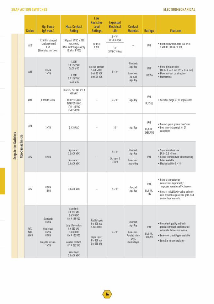
SNAP ACTION SWITCHES ELECTROMECHANICAL
16
SeriesOp. Force(gF max.)
Max. Contact Rating
Low Resistive
Load Ratings
Expected Electrical
LifeContact Material Ratings Features
Snap
Act
ion
Switc
hes
Non-
Seal
ed (m
icro
)
AEQ
1.2N (Pin plunger)1.7N (Leaf lever)
1.5N (Simulated leaf lever)
100 μA at 3 VDC to 100 mA 30 VDC
[Min. switching capacity 10 μA at 1 VDC]
10 μA at1 VDC
2 × 10⁵
3V DC 0.1mA
— IP40 • Handles low level load 100 μA at 3 VDC to 100 mA 30 VDC105
30V DC 100mA
AH1 0.74N1.47N
1.47N3 A 125 V AC2 A 30 V DC
0.74N1 A 125 V AC1 A 30 V DC
Au-clad contact5 mA 6 VDC
2 mA 12 VDC1 mA 24 VDC
3 × 10⁴
Standard: Ag alloy
Low-level: Au-cladAg alloy
IP40
UL/CSA
• Ultra-miniature size (12.8 × 6 × 6.5 mm 12.7 × 6 × 6 mm)
• Flux-resistant construction• Flat terminal
AM1 0.69N to 5.30N
10 A 125, 250 VAC or 1 A 480 VAC
1/8HP 125 VAC1/4HP 250 VAC1/2A 125 VDC1/4A 250 VDC
— 5 × 10⁵ Ag alloyIP40
UL/C-UL• Versatile range for all applications
AV3 1.47N 3 A 30 VAC — 104 Ag alloy
IP40
UL/C-UL, ENEC/VDE
• Contact gap of greater than 1mm• Door inter-lock switch for OA
equipment
AV4 0.98N
Ag contact:0.5 A 30 VDC
Au contact:0.1 A 30 VDC
—
2 × 10⁴
(Au type: 2 × 10⁵)
Standard: Ag alloy
Low-level: Au plating
IP40
• Super miniature size (7.5 × 2.5 × 5 mm)
• Solder terminal type with mounting holes available
• Mechanical life 3 × 10⁵
AV6 0.50N1.50N 0.1 A 30 VDC — 2 × 10⁵ Au-clad
Ag alloy
IP40
UL/C-UL, TÜV
• Using a connector for connections significantly improves operation effectiveness
• Contact reliability by using a simple dust prevention guard and gold-clad double layer contacts
AVT3AVL3AVM3
Standard:0.25N
Gold-clad:0.49N0.98N
Long life version:1.47N
Standard:3 A 250 VAC3 A 30 VDC
0.4 A 125 VDC
Long life version:5 A 250 VAC5 A 30 VDC
0.4 A 125 VDC
Au clad contact:0.1 A 250 VAC
Triple layer:0.1 A 30 VDC
Double layer:1 to 100 mA,5 to 30 VDC
Triple layer:1 to 100 mA,5 to 250 VAC
5 × 10⁴
Standard: Ag alloy
Low-level: Au-clad triple
layer,double layer
IP40
UL/C-UL, ENEC/VDE
• Consistent quality and high precision through sophisticated automatic fabrication system
• Low-level circuit types available
• Long life version available

17
ELECTROMECHANICAL SNAP ACTION SWITCHES
SeriesOp. Force(gF max.)
Max. Contact Rating
Low Resistive
Load Ratings
Expected Electrical
LifeContact Material Ratings Features
Snap
Act
ion
Switc
hes
Seal
ed (t
urqu
oise
)
ASQ1.5N (Pin plunger)1.7N (Leaf lever)
1.5N (Simulated leaf lever)
100 mA 30 VDC 1 mA 5 VDC
2 × 10⁵(Nominal)
Au-clad IP67• Compact size and ultra-long stroke• IP67• Silent operation2 × 105
(Low-level)
ASQM 1.2N (Pin Plunger)1.5N(Simulated Roller) 50mA 16 VDC 1mA 5 VDC
1.5X10^5 (nominal)
Au-Clad 1P67
• Miniaturization• Contact pressure does not depend on
the operation stroke• Hgh contact relibility• High effective sealing for resistance
against adverse environments3x10^5
(low level)
ABJ
1.23N
1.96N
2.45N(Long stroke)
Ag Alloy Contact: 1.23N
1 A 125 VAC1 A 30 VDC
1.96N2 A 125 VAC2 A 30 VDC
2.45N (Long stroke)1 A 125 VAC1 A 30 VDC
5 mA 6 VDC2 mA 12 VDC1 mA 24 VDC
3 × 10⁴(Ag alloycontact)
Standard:Ag alloy
Low-level: Au-clad
IP67
UL/CSA
• Ultra-miniature size (12.8 × 6 × 6.5 mm)
• Adoption of elastomer double molding technology and Ultrasonic swaging technology to uniform sealing in high production quantities
• High environmental resistance (IP67)105
(Au-cladcontact)
Au Clad Contact:0.1 A 125 VAC0.1 A 30 VDC
ABS 0.98N1.47N
Ag Alloy Contact: 2 A 125 VAC2 A 250 VAC2 A 30 VDC
0.4 A 125 VDC5 mA 6 VDC
2 mA 12 VDC1 mA 24 VDC
5 × 10⁴(Ag alloycontact)
Standard: Ag alloy
Low-level: Au-clad
IP67
UL/C-UL ENEC/VDE
• Sub-miniature size (19.8 × 6.4 × 11.1 mm)
• Adoption of Elastomer double molding technology and Ultrasonic swaging technology to uniform sealing in high production quantities
• High environmental resistance (IP67)
Au Clad Contact:(triple, double layer)
0.1 A 125 VAC0.1 A 250 VAC0.1 A 30 VDC
2 × 10⁵(Au-cladcontact)
ABV 0.98N1.96N
Ag Alloy Contact: 5 A 250 VAC
(O.F. min. 1.96N)3 A 250 VAC(O.F. 0.98N)
5 mA 6 VDC2 mA 12 VDC1 mA 24 VDC
105(Nominal)
Standard:Ag alloy
Low-level: Au-clad
IP67
UL/C-UL ENEC/VDE
• Miniature size (33 × 10.3 × 15.9 mm)
• Adoption of Ultrasonic swaging technology and epoxy sealing to uniform sealing in high production quantitiest
• High environmental resistance (IP67)
Au Clad Contact:3 A 250 VAC
(O.F. min. 1.96N)1 A 250 VAC(O.F. 0.98N)
106(Low-level)
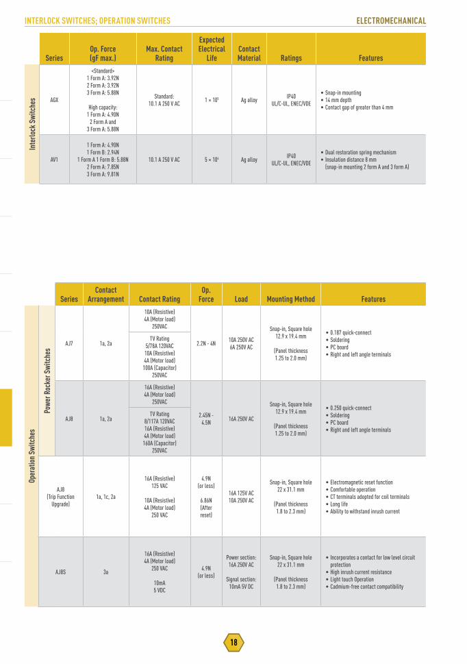
INTERLOCK SWITCHES; OPERATION SWITCHES ELECTROMECHANICAL
18
SeriesContact
Arrangement Contact RatingOp.
Force Load Mounting Method Features
Oper
atio
n Sw
itche
s
Powe
r Roc
ker S
witc
hes
AJ7 1a, 2a
10A (Resistive)4A (Motor load)
250VAC
2.2N - 4N 10A 250V AC6A 250V AC
Snap-in, Square hole12.9 x 19.4 mm
(Panel thickness1.25 to 2.0 mm)
• 0.187 quick-connect• Soldering• PC board• Right and left angle terminals
TV Rating5/78A 120VAC10A (Resistive) 4A (Motor load) 100A (Capacitor)
250VAC
AJ8 1a, 2a
16A (Resistive)4A (Motor load)
250VAC
2.45N - 4.5N 16A 250V AC
Snap-in, Square hole12.9 x 19.4 mm
(Panel thickness1.25 to 2.0 mm)
• 0.250 quick-connect• Soldering• PC board• Right and left angle terminals
TV Rating8/117A 120VAC16A (Resistive) 4A (Motor load) 160A (Capacitor)
250VAC
AJ8(Trip Function
Upgrade)1a, 1c, 2a
16A (Resistive)125 VAC
10A (Resistive)4A (Motor load)
250 VAC
4.9N(or less)
6.86N(After reset)
16A 125V AC10A 250V AC
Snap-in, Square hole22 x 31.1 mm
(Panel thickness1.8 to 2.3 mm)
• Electromagnetic reset function• Comfortable operation• CT terminals adopted for coil terminals• Long life• Ability to withstand inrush current
AJ8S 3a
16A (Resistive)4A (Motor load)
250 VAC
10mA5 VDC
4.9N(or less)
Power section:16A 250V AC
Signal section:10mA 5V DC
Snap-in, Square hole22 x 31.1 mm
(Panel thickness1.8 to 2.3 mm)
• Incorporates a contact for low level circuit protection
• High inrush current resistance• Light touch Operation• Cadmium-free contact compatibility
SeriesOp. Force(gF max.)
Max. Contact Rating
Expected Electrical
LifeContact Material Ratings Features
Inte
rlock
Swi
tche
s AGX
<Standard>1 Form A: 3.92N2 Form A: 3.92N3 Form A: 5.88N
High capacity:1 Form A: 4.90N
2 Form A and3 Form A: 5.88N
Standard:10.1 A 250 V AC 1 × 10⁵ Ag alloy IP40
UL/C-UL, ENEC/VDE
• Snap-in mounting• 14 mm depth• Contact gap of greater than 4 mm
AV1
1 Form A: 4.90N1 Form B: 2.94N
1 Form A 1 Form B: 5.88N2 Form A: 7.85N3 Form A: 9.81N
10.1 A 250 V AC 5 × 10⁴ Ag alloy IP40UL/C-UL, ENEC/VDE
• Dual restoration spring mechanism• Insulation distance 8 mm
(snap-in mounting 2 form A and 3 form A)

19
ELECTROMECHANICAL ENCODERS & POTENTIOMETERS
Series Life (cycles) Rotation Torque FeaturesEn
code
rs
18mm SquareWaterproof EVQ-V9 30,000 50 mN·m
• Water resistant• Highly responsive click sound and feel• High precision and reliability
11 mm Square GS Encoders
EVE-VEVE-Y 30,000 3 to 20 mN-m
• Low Profile• Reflow Type 3.5mm Body Height• Through-Hole Type 4mm Body Height• Integrated Push Switch 0.4mm or 1.5mm Travel• Minimum-Wobble Type Available
16 mm SquareHigh Grade EVE-P 1,000,000 3 to 25 mN-m
• Smooth operating feel with minimal wobble• Integrated Switch• Long Life: 1,000,000 cycles minimum
Center Space20/12mm, 27/18mm,
60/40mmEVQ-V/W 30,000 3 to 20 mN-m
35 mN-m
• Open center space for LED and switch• Allows for large knob design
Series Life (cycles) Rotation Torque Features
Pote
ntio
met
ers
9mmRotary EVU-E/F 10,000 1 to 20 mN-m • Multiple Bushing & Height Configurations
• Midpoint detent optional
10mm Sensor EVW-AE 1,000,000 3 mN-m max. • Low profile, small size, long life• <3% linearity
Center Space39/20mm EWV-YE/YG/YJ/YK 30,000 20 mN-m
• Large center space for switch and LED• Low wobble of 0.25mm max• Multiple detent options (5, 8, 29)• Automotive grade• With built-in LED option
Bluetooth® RF Modules802.15.4 (Mesh) RF Modules ISM (Industrial, Scientific, Medical) RF ModulesWiFi, WiFi + BT RF Modules
WIRELESS CONNECTIVITY
21
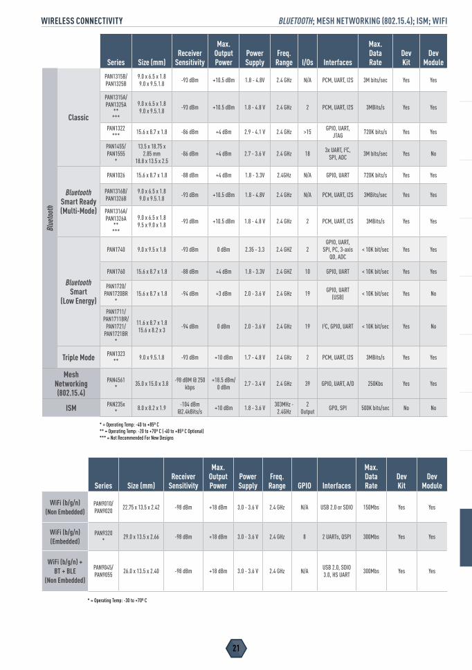
WIRELESS CONNECTIVITY BLUETOOTH; MESH NETWORKING (802.15.4); ISM; WIFI
Series Size (mm)Receiver
Sensitivity
Max.Output Power
PowerSupply
Freq.Range I/Os Interfaces
Max. DataRate
Dev Kit
Dev Module
Bluetooth
Classic
PAN1315B/PAN1325B
9.0 x 6.5 x 1.8 9.0 x 9.5.1.8 -93 dBm +10.5 dBm 1.8 - 4.8V 2.4 GHz N/A PCM, UART, I2S 3M bits/sec Yes Yes
PAN1315A/ PAN1325A
** ***
9.0 x 6.5 x 1.8 9.0 x 9.5.1.8 -93 dBm +10.5 dBm 1.8 - 4.8 V 2.4 GHz 2 PCM, UART, I2S 3MBits/s Yes Yes
PAN1322*** 15.6 x 8.7 x 1.8 -86 dBm +4 dBm 2.9 - 4.1 V 2.4 GHz >15 GPIO, UART,
JTAG 720K bits/s Yes Yes
PAN1455/ PAN1555
*
13.5 x 18.75 x 2.85 mm
18.8 x 13.5 x 2.5-86 dBm +4 dBm 2.7 - 3.6 V 2.4 GHz 18 3x UART, I2C,
SPI, ADC 3M bits/sec Yes No
Bluetooth Smart Ready (Multi-Mode)
PAN1026 15.6 x 8.7 x 1.8 -88 dBm +4 dBm 1.8 - 3.3V 2.4GHz N/A GPIO, UART 720K bits/s Yes Yes
PAN1316B/PAN1326B
9.0 x 6.5 x 1.8 9.0 x 9.5.1.8 -93 dBm +10.5 dBm 1.8 - 4.8V 2.4 GHz N/A PCM, UART, I2S 3MBits/sec Yes Yes
PAN1316A/ PAN1326A
*****
9.0 x 6.5 x 1.8 9.5 x 9.0 x 1.8 -93 dBm +10.5 dBm 1.8 - 4.8 V 2.4 GHz 2 PCM, UART, I2S 3MBits/s Yes Yes
Bluetooth Smart
(Low Energy)
PAN1740 9.0 x 9.5 x 1.8 -93 dBm 0 dBm 2.35 - 3.3 2.4 GHZ 2GPIO, UART,
SPI, PC, 3-axis QD, ADC
< 10K bit/sec Yes Yes
PAN1760 15.6 x 8.7 x 1.8 -88 dBm +4 dBm 1.8 - 3.3V 2.4 GHZ 10 GPIO, UART < 10K bit/sec Yes Yes
PAN1720/PAN1720BR
*15.6 x 8.7 x 1.8 -94 dBm +3 dBm 2.0 - 3.6 V 2.4 GHz 19 GPIO, UART
(USB) < 10K bit/sec Yes No
PAN1711/ PAN1711BR/
PAN1721/ PAN1721BR
*
11.6 x 8.7 x 1.815.6 x 8.2 x 3 -94 dBm 0 dBm 2.0 - 3.6 V 2.4 GHz 19 I2C, GPIO, UART < 10K bit/sec Yes No
Triple Mode PAN1323** 9.0 x 9.5.1.8 -93 dBm +10 dBm 1.7 - 4.8 V 2.4 GHz 2 PCM, UART, I2S 3MBits/s Yes Yes
Mesh Networking (802.15.4)
PAN4561* 35.0 x 15.0 x 3.8 -98 dBM @ 250
kbps+18.5 dBm/
0 dBm 2.7 - 3.4 V 2.4 GHz 39 GPIO, UART, A/D 250Kbs Yes Yes
ISM PAN235x* 8.0 x 8.2 x 1.9 -104 dBm
@2.4kBits/s +10 dBm 1.8 - 3.6 V 303MHz - 2.4GHz
2Output GPO, SPI 500K bits/sec No No
* = Operating Temp: -40 to +85º C** = Operating Temp: -20 to +70º C (-40 to +85º C Optional)*** = Not Recommended For New Designs
Series Size (mm)Receiver
Sensitivity
Max.Output Power
PowerSupply
Freq.Range GPIO Interfaces
Max. DataRate
Dev Kit
Dev Module
WiFi (b/g/n) (Non Embedded)
PAN9010/ PAN9020 22.75 x 13.5 x 2.42 -98 dBm +18 dBm 3.0 - 3.6 V 2.4 GHz N/A USB 2.0 or SDIO 150Mbs Yes Yes
WiFi (b/g/n) (Embedded)
PAN9320* 29.0 x 13.5 x 2.66 -98 dBm +18 dBm 3.0 - 3.6 V 2.4 GHz 8 2 UARTs, QSPI 300Mbs Yes Yes
WiFi (b/g/n) + BT + BLE
(Non Embedded)
PAN9045/PAN9055 26.0 x 13.5 x 2.40 -98 dBm +18 dBm 3.0 - 3.6 V 2.4 GHz N/A USB 2.0, SDIO
3.0, HS UART 300Mbs Yes Yes
* = Operating Temp: -30 to +70º C
WIRELESS CONNECTIVITY
Chip ResistorsCurrent Sensing ResistorsHigh Precision Chip ResistorsAnti-Sulfurated Chip ResistorsWide Terminal Chip ResistorsAxial Leaded ResistorsResistor Networks & Arrays
RESISTORS

23
RESISTORS CHIP RESISTORS
SeriesCaseSize
PowerRating
(W)ResistanceRange (Ω)
ResistanceTolerance
(%)T.C.R.
(ppm/dC)
LxWxTDimensions
(mm)
Qty.7” Reel (pcs.) Features
Chip
Res
isto
rs
Thic
k Fi
lm C
hip
ERJ-XGNJ, 0• 01005 1/32 W 0, 10 ~ 1 M ± 5, jumper ± 200*0.40 x 0.20 x 0.13 20,000
• Small size and lightweight
• High reliability using metal glaze thick film resistive element and three layers of electrodes
• Compatible with automatic placement of bulk taping and bulk case packaging
• Meets ISO-9001 & TS16949 standards
• AEC Q200 Certified
• Halogen Free
ERJ-XGNF• 01005 1/32 W 10 ~ 1 M ± 1 ± 200
ERJ-1GNJ, 0 0201 1/20 W 0, 1.0 ~ 1 M ± 5, jumper ± 200*
0.60 x 0.3 x 0.23 15,000ERJ-1GNF 0201 1/20 W 10 ~ 1 M ± 1 ± 200
ERJ-1RHD 0201 1/20 W 1 K to 1 M ± 0.5 ± 50
ERJ-2GEJ, 0 0402 1/16 W 0, 1.0 ~ 2.2 M ± 5, jumper ± 200*
1.0 x 0.5 x 0.35 10,000ERJ-2RKF 0402 1/16 W 10 ~ 1 M ± 1 ± 100
ERJ-2RHD 0402 1/16 W 100 to 100 K ± 0.5 ± 50
ERJ-2RKD 0402 1/16 W 10 to 97.6 & 102 K to 1 M ± 0.5 ± 50
ERJ-3GEYJ, 0 0603 1/10 W 0, 1.0 ~ 10 M ± 5, jumper ± 200*
1.6 x 0.8 x 0.45 5,000
ERJ-3EKF 0603 1/10 W 10 ~ 1 M ± 1 ± 100
ERJ-3RBD 0603 1/8 W 100 to 100 K ± 0.5 ± 50
ERJ-3RED 0603 1/8 W 10 to 97.6 & 102 K to 1 M ± 0.5 ± 100
ERJ-PB3 0603 1/5 W 200 to 200 K ± 0.1, ± 0.5 ± 50
ERJ-6GEYJ, 0 0805 1/8 W 0, 1.0 ~ 10 M ± 5, jumper ± 200*
2.0 x 1.25 x 0.6 5,000
ERJ-6ENF 0805 1/8 W 10 ~ 2.2 M ± 1 ± 100
ERJ-6RBD 0805 1/8 W 100 to 100 K ± 0.5 ± 50
ERJ-6RED 0805 1/8 W 10 to 97.6 and 102 K to 1 M ± 0.5 ± 100
ERJ-PB6 0805 1/4 W 200 ~ 1 M ± 0.1, ± 0.5 ± 50
ERJ-8GEYJ, 0 1206 1/4 W 0, 1.0 ~ 10 M ± 5, jumper ± 200*3.2 x 1.6 x 0.6 5,000
ERJ-8ENF 1206 1/4 W 10 ~ 2.2 M ± 1 ± 100
ERJ-14YJ, 0 1210 1/4 W 0, 1.0 ~ 10 M ± 5, jumper ± 200*3.2 x 2.5 x 0.6 5,000
ERJ-14NF 1210 1/4 W 10 ~ 1 M ± 1 ± 100
ERJ-12ZYJ, 0 2010 1/2 W 0, 1.0 ~ 10 M ± 5, jumper ± 2005.0 x 2.5 x 0.6 5,000
ERJ-12SF 2010 1/2 W 10 ~ 1 M ± 1 ± 100
ERJ-1TYJ, 0 2512 1 W 0, 1.0 ~ 1 M ± 5, jumper ± 200*6.4 x 3.2 x 0.6 4,000
ERJ-1TNF 2512 1 W 10 ~ 1 M ± 1 ± 100
Anti-
Surg
e Thi
ck Fi
lm C
hip
ERJ-PA2 0402 1/5 W 10 ~ 1 M±0.5, ±1 ±100
1.0 x 0.5 x 0.35 10,000+5 ±200
ERJ-P03 0603 1/5 W10 ~ 1 M ±0.5, ±1 ±150, ±200
1.60 x 0.8 x 0.45
5,000
• Anti-Surge characteristics superior to standard metal film resistors
• High reliability
• High Power in Small Packages
• High Temperature
• Meets ISO-9001 & TS16949 standards
• AEC Q200 Certified
1 ~ 1 M +5 R>10 Ω: ±200 R<10Ω: -150 to 400
ERJ-PA3 0603 1/4 W10 ~ 1 M ±0.5, ±1 ±100
1.6 x 0.8 x 0.451 ~ 1.5 M +5 ±200
ERJ-P06 0805 1/2 W
1 ~ 1 M ±0.5, ±1 R≥30 Ω: ±100 R<30Ω: ±300
2.0 x 1.25 x 0.60
1 ~ 3.3 M +5 R≥30 Ω: ±200 R<30Ω: ±300
ERJ-P08 1206 2/3 W
10 ~ 1 M ±0.5, ±1 ±100
3.2 x 1.6 x 0.601 ~ 10 M +5 R≥10 Ω: ±200
R<10Ω: -100 to +600
ERJ-P14 1210 1/2 W10 ~ 1 M ±0.5, ±1 ±100
3.2 x 2.5 x 0.601 ~ 1 M +5 R≥10 Ω: ±200
R<10Ω: -100 to +600
ERJ-P6W 0805 1/2 W10 ~ 1 M ±1 ±200
2.0 x 1.25 x 0.651 ~ 1 M +5 R < 10 : -100 to +600
10 < R : +-200
Anti-
Puls
e Thi
ck
Film
Chi
p
ERJ-T06 0805 1/4 W 1 ~ 1 M +5R≥33 Ω: ±200 R<30Ω: ±300
R<10Ω: -100 to +6002.0 x 1.25 x 0.60
5,000
• Pulse Tolerant
• High Reliability
• High Power
• Meets ISO-9001 & TS16949 standards
• AEC Q200 Certified
ERJ-T08 1206 1/3 W 1 ~ 1M +5 R≥10 Ω: ±200 R<10Ω: -100 to +600 3.2 x 1.6 x 0.60
ERJ-T14ERJ-T14L 1210 1/2 W 1 ~ 1M
+5 R≥10 Ω: ±200 R<10Ω: -100 to +600 3.2 x 2.5 x 0.60
±10, ±20
RESISTORS
*TCR listed is for 10 ~ 1M Ω. Check data sheet for less than 10 Ω and greater than 1M Ω.•Not AEC Q200 Certified.

CURRENT SENSING RESISTORS RESISTORS
24
SeriesCaseSize
PowerRating
(W)ResistanceRange (Ω)
ResistanceTolerance
(%)T.C.R.
(ppm/dC)
LxWxTDimensions
(mm)
Qty.7” Reel (pcs.) Features
Curre
nt S
ensi
ng R
esis
tors
Thic
k Fi
lm C
hip
ERJ-2BS 0402 1/8 W 0.1 ~ 0.2 ± 1, ± 5 ± 3001.0 x 0.5 x 0.35
10,000
• Low Ohmic
• Small size and lightweight
• High reliability using metal glaze thick film resistive elements and three layers of electrodes
• Compatible with automatic placement of bulk taping and bulk case packaging
• Meets ISO-9001 & TS16949 standards
• AEC Q200 Certified
• Halogen Free
ERJ-2BQ 0402 1/8 W 0.22 ~ 1.0 ± 1, ± 5 ±250 10,000
ERJ-3RS 0603 1/10 W 0.1 ~ 0.2 ± 1, ± 2, ± 5 ±250
1.6 x 0.8 x 0.45
5,000
ERJ-3RQ 0603 1/10 W 0.22 ~ 9.1 ± 1, ± 2, ± 5 ±200, ±250 5,000
ERJ-3BS 0603 1/4 W 0.1 ~ 0.2 ± 1, ± 2, ± 5 ±300 5,000
ERJ-3BQ 0603 1/4 W 0.22 ~ 0.91 ± 1, ± 2, ± 5 ±200, ±300 5,000
ERJ-6RS 0805 1/8 W 0.1 ~ 0.2 ± 1, ± 2, ± 5 ±250
2.0 x 1.25 x 0.6
5,000
ERJ-6RQ 0805 1/8 W 0.22 ~ 0.91 ± 1, ± 2, ± 5 ±200, ±250 5,000
ERJ-6BS 0805 1/3 W 0.1 ~ 0.2 ± 1, ± 2, ± 5 ±250 5,000
ERJ-6BQ 0805 1/3 W 0.22 ~ 0.91 ± 1, ± 2, ± 5 ±200, ±250 5,000
ERJ-8RS 1206 1/4 W 0.1 ~ 0.2 ± 1, ± 2, ± 5 ±250
3.2 x 1.6 x 0.6
5,000
ERJ-8RQ 1206 1/4 W 0.22 ~ 0.91 ± 1, ± 2, ± 5 ±200, ±250 5,000
ERJ-8BS 1206 1/2 W 0.1 ~ 0.2 ± 1, ± 2, ± 5 ±200 5,000
ERJ-8BQ 1206 1/2 W 0.22 ~ 0.91 ± 1, ± 2, ± 5 ±100, ±200 5,000
ERJ-14RS 1210 1/4 W 0.1 ~ 0.2 ± 1, ± 2, ± 5 ±2003.2 x 2.5 x 0.6
5,000
ERJ-14RQ 1210 1/4 W 0.22 ~ 0.91 ± 1, ± 2, ± 5 ±100, ±200 5,000
ERJ-14BS 1210 1/2 W 0.1 ~ 0.2 ± 1, ± 2, ± 5 ±2003.2 x 2.5 x 0.6
5,000
ERJ-14BQ 1210 1/2 W 0.22 ~ 0.91 ± 1, ± 2, ± 5 ±100, ±200 5,000
ERJ-12RS 1812 1/2 W 0.1 ~ 0.2 ± 1, ± 2, ± 5 ±2004.5 x 3.2 x 0.6
5,000
• Low Ohmic
• Small size and lightweight
• High reliability using metal glaze thick film resistive elements and three layers of electrodes
• Compatible with automatic place-ment of bulk taping and bulk case packaging
• Meets ISO-9001 & TS16949 standards
• AEC Q200 Certified
• Halogen Free
ERJ-12RQ 1812 1/2 W 0.22 ~ 0.91 ± 1, ± 2, ± 5 ±100, ±200 5,000
ERJ-12ZS 2010 1/2 W 0.1 ~ 0.2 ± 1, ± 2, ± 5 ±2005.0 x 2.5 x 0.6
5,000
ERJ-12ZQ 2010 1/2 W 0.22 ~ 0.91 ± 1, ± 2, ± 5 ±100, ±200 5,000
ERJ-1TRS 2512 1 W 0.1 ~ 0.2 ± 1, ± 2, ± 5 ±2006.4 x 3.2 x 0.6 4,000
ERJ-1TRQ 2512 1 W 0.22 ~ 0.91 ± 1, ± 2, ± 5 ±100, ±200
ERJ-2LW 0402 1/5 W 10 m ± 1, +-2, +-5 0 to 500 1.0 x 0.5 x0.4 10,000
ERJ-2BW* 0402 1/4 W 0.047 ~ 0.2 ± 2, ± 5 ±300 1.0 x 0.5 x 0.35 10,000
ERJ-3LW ‘0402 1/4 W 5 m ~10 m ± 1, ± 2, ± 5 5 m: 0 to 700 10 m: 0 to 300 1.6 x 0.8 x0.55 5,000
ERJ-3BW* 0603 1/4 W 20 m ~ 100 m ± 1, ± 2, ± 5 ±150, ±250 1.6 x 0.8 x 0.55 5,000
ERJ-6BW 0805 1/3 W 10 m ~ 50 m ± 1, ± 2, ± 5 ±200, ±300 2.0 x 1.25 x 0.65 5,000
ERJ-8BW 1206 1 W 0.01 ~ 0.1 ± 1, ± 2, ± 5 ±100, ±150, ±200 32 x 1.6 x 0.6 5,000
ERJ-8CW 1206 1 W 10 m ~ 50 m ± 1, ± 2, ± 5 ±75 3.2 x 1.6 x 0.65 5,000
ERJ-L03 0603 1/5 W 47 ~ 100 m ± 1, ± 5 ± 200 1.6 x 0.8 x 0.45 5,000
ERJ-L06 0805 1/4 W 47 ~ 100 m ± 1, ± 5 ± 100 2.0 x 1.25 x 0.6 5,000
ERJ-L08 1206 1/3 W 47 ~ 100 m ± 1, ± 5 ± 100 3.2 x 1.6 x 0.6 5,000
ERJ-L14 1210 1/3 W 20 ~ 100 m ± 1, ± 5
R < 47 milli: ± 300R≥ 47 milli: ± 100
3.2 x 2.5 x 0.6 5,000
ERJ-L12 1812 1/2 W 20 ~ 100 m ± 1, ± 5 4.5 x 3.2 x 0.6 5,000
ERJ-L1D 2010 1/2 W 40 ~ 100 m ± 1, ± 5 5.0 x 2.5 x 0.6 5,000
ERJ-L1W 2512 1 W 40 ~ 100 m ± 5 6.4 x 3.2 x 1.1 3,000
ERJ-M1WT 2512 1 W 3, 4 m ± 1, ± 5 ± 350 6.4 x 3.2 x 0.8 3,000
• Low Ohmic
• Meets ISO-9001 & TS16949 standards
• AEC Q200 Certified
• High Power
ERJ-M1WT 2512 1 W 5, 6, 10, 15, 20 m ± 1, ± 5 ± 100 6.4 x 3.2 x 0.8 3,000
ERJ-M1WS 2512 1 W 1, 1.5 m ± 1, ± 5 350 ± 100 6.4 x 3.2 x 0.8 3,000
ERJ-M1WS 2512 1 W 2, 3, 4 m ± 1, ± 5 100 ± 50 6.4 x 3.2 x 0.8 3,000
ERJ-MS4S 2512 3 W 1, 2, 3, 4 m ± 1 ± 75 6.4 x 3.2 x 1.2 2,000
ERJ-MS4H 2512 3 W 5, 6 m ± 1 ± 75 6.4 x 3.2 x 1.2 2,000
ERJ-MS4H 2512 2 W 7, 8, 9, 10 m ± 1 ± 75 6.4 x 3.2 x 1.2 2,000
ERJ-MS6S 2526 5 W 0.5, 1, 2 m ± 1 ± 75 6.4 x 6.8 x 1.2 1,000
ERJ-MP2 1206 0.5 ~ 1 W 1 ~ 50 m ± 1 ± 75 3.2 x 1.6 x 0.6 3,000
ERJ-MP3 2010 0.5 ~ 2 W 1 ~ 50 m ± 1 ± 75 5.0 x 2.5 x 0.6 3,000
ERJ-MP4 2512 1 ~ 3 W 1 ~ 50 m ± 1 ± 75 6.4 x 3.2 x 1.2 2,000
Met
al P
late
*Not AEC Q200 Certified.
25
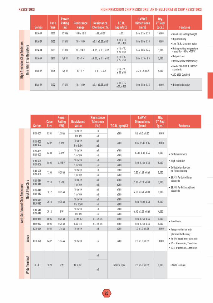
RESISTORS HIGH PRECISION CHIP RESISTORS; ANTI-SULFURATED CHIP RESISTORS
SeriesCaseSize
PowerRating
(W)Resistance
RangeResistance
Tolerance (%)T.C.R.
(ppm/dC)
LxWxTDimensions
(mm)
Qty.7” Reel (pcs.) Features
High
Pre
cisi
on C
hip R
esis
tors
Thin
Film
Chi
p Res
isto
rs
ERA-1A 0201 1⁄20 W 100 to 10 K ±01, ±0.25 ± 25 0.6 x 0.3 x 0.23 15,000 • Small size and lightweight
• High reliability
• Low T.C.R. & current noise
• High operating temperature capability: -55 to +155ºC
• Halgoen Free
• Reflow & flow solderability
• Meets ISO-9001 & TS16949 standards
• AEC Q200 Certified
ERA-2A 0402 1/16 W 10 - 100K ±0.1, ±0.25, ±0.5 ± 10, ± 15 ± 25, ± 100 1.0 x 0.5 x 0.35 10,000
ERA-3A 0603 1/10 W 10 ~ 330 K ± 0.05, ± 0.1, ± 0.5 ± 10, ± 15, ± 25, ± 50 1.6 x .80 x 0.45 5,000
ERA-6A 0805 1/8 W 10 ~ 1 M ± 0.05, ± 0.1, ± 0.5 ± 10, ± 15, ± 25, ± 50 2.0 x 1.25 x 0.5 5,000
ERA-8A 1206 1/4 W 10 ~ 1 M ± 0.1, ± 0.5 ± 10, ± 15, ± 25, ± 50 3.2 x 1.6 x 0.6 5,000
ERA-2H 0402 1/16 W 10 - 100K ±0.1, ±0.25, ±0.5 ± 10, ± 15 ± 25, ± 100 1.0 x 0.5 x 0.35 10,000 • High sound quality
SeriesCase Size
Power Rating
(W)Resistance
Value
Resistance Tolerance
(%) T.C.R (ppm/C)
LxWxT Dimensions
(mm)
Qty.7” Reel (pcs.) Features
Anti-
Sulfu
rate
d Chi
p Res
isto
rs
Thic
k Fi
lm C
hip
ERJ-U01 0201 1/20 W10 to 1M ±1
±200 0.6 x 0.3 x 0.23 15,000
• Sulfur resistance
• High reliability
• Suitable for flow and re-flow soldering
• ERJ-S: Au-based inner electrode
• ERJ-U: Ag-Pd-based inner electrode
1 to 1M ±5
ERJ-S02ERJ-U02 0402 0.1 W
10 to 1M ±1±200 1.0 x 0.50 x 0.35 10,000
1 to 3.3M ±5
ERJ-S03 ERJ-U03 0603 0.1 W
10 to 1M ±1 ±1001.60 x 0.8 x 0.45 5,000
1 to 10M ±5 ±200
ERJ-S06 ERJ-U06 0805 0.125 W
10 to 1M ±1 ±1002.0 x 1.25 x 0.60 5,000
1 to 10M ±5 ±200
ERJ-S08 ERJ-U08 1206 0.25 W
10 to 1M ±1 ±1003.20 x 1.60 x 0.60 5,000
1 to 10M ±5 ±200
ERJ-S14 ERJ-U14 1210 0.5 W
10 to 1M ±1 ±1003.20 x 2.50 x 0.60 5,000
1 to 10M ±5 ±200
ERJ-S12 ERJ-U12 1812 0.75 W
10 to 1M ±1 ±1004.50 x 3.20 x 0.60 5,000
1 to 10M ±5 ±200
ERJ-S1D ERJ-U1D 2010 0.75 W
10 to 1M ±1 ±1005.0 x 2.50 x 0.60 5,000
1 to 10zM ±5 ±200
ERJ-S1T ERJ-U1T 2512 1 W
10 to 1M ±1 ±1006.40 x 3.20 x 0.60 4,000
1 to 1M ±5 ±200
ERJ-U6S 0805 0.25 W 0.1 to 0.2 ±1, ±2, ±5 ±150 2.0 x 1.25 x 0.55 5,000• Low Ohmic
ERJ-U6Q 0805 0.25 W 0.22 to 1 ±1, ±2, ±5 ±150 2.0 x 1.25 x 0.55 5,000
EXB-U24 0402 1/16 W 10 to 1M ±5 ±200 1.0 x 1.0 x 0.35 10,000 • Array solution for high
placement efficiency
• Ag-Pb-based inner electrode
• U24: 4 terminals, 2 resistors
• U28: 8 terminals, 4 resistors
EXB-U28 0402 1/16 W 10 to 1M ±5 ±200 2.0 x 1.0 x 0.35 10,000
Wid
e Ter
min
al
ERJ-C1 1020 2 W 10 m to 1
±1
Refer to Spec 2.5 x 5.0 x 0.55 5,000 • Wide Terminal
±5
Arra
y
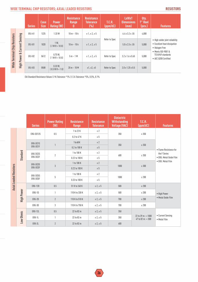
WIDE TERMINAL CHIP RESISTORS; AXIAL LEADED RESISTORS RESISTORS
26
SeriesCaseSize
PowerRating (W)
ResistanceRange
Ω
ResistanceTolerance
(%)T.C.R.
(ppm/dC)
LxWxTDimensions
(mm)
Qty.7” Reel (pcs.) Features
Wid
e Ter
min
al C
hip R
esis
tors
High
Pow
er &
Cur
rent
Sen
sing ERJ-A1 1225 1.33 W 10 m ~ 10 k ± 1, ± 2, ± 5
Refer to Spec
6.4 x 3.2 x .55 4,000
• High solder joint reliability• Excellent heat dissipation• Halogen Free• Meets ISO-9001 &
TS16949 standards• AEC Q200 Certified
ERJ-B1 1020 1 W,( 2 W R < 10 Ω) 10 m ~ 10 k ± 1, ± 2, ± 5 5.0 x 2.5 x .55 5,000
ERJ-B2 0612 0.75 W, ( 1 W R < 10 Ω) 5 m ~ 1 M ± 1, ± 2, ± 5 Refer to Spec 3.2 x 1.6 x 0.65 5,000
ERJ-B3 0508 0.33 W,( 0.5 W R < 1 Ω) 20 m ~ 10 M ±1, ±2, ±5 Refer to Spec 2.0 x 1.25 x 0.5 5,000
EIA Standard Resistance Values E-96 Tolerance *1% | E-24 Tolerance *5%, 0.5%, 0.1%
SeriesPower Rating
(W)Resistance
RangeResistance Tolerance
Dielectric Withstanding Voltage (VAC)
T.C.R. (ppm/dC) Features
Axia
l Lea
ded R
esis
tors
Stan
dard
ERG-(X)12S 0.51 to 22 K ± 2
350 ± 350
• Flame Resistance for the F Series
• ERG: Metal Oxide Film• ERX: Metal Film
0.2 to 47 K ± 5
ERG-(X)1SERG-(X)1F 1
1 to 68 K ± 2350 ± 350
0.2 to 100 K ± 5
ERG-(X)2SERG-(X)2F 2
1 to 100 K ± 2600 ± 350
0.22 to 100 K ± 5
ERG-(X)3SERG-(X)3F 3
1 to 100 K ± 21000 ± 300
0.22 to 100 K ± 5
ERG-(X)5SERG-(X)5F 5
1 to 100 K ± 21000 ± 200
0.33 to 100 K ± 5
High
Pow
er
ERG-12D 0.5 51 K to 240 K ± 2, ± 5 500 ± 200
• High Power• Metal Oxide Film
ERG-1D 1 110 K to 330 K ± 2, ± 5 500 ± 200
ERG-2D 2 110 K to 510 K ± 2, ± 5 700 ± 200
ERG-3D 3 110 K to 750 K ± 2, ± 5 700 ± 200
Low
Ohm
ic ERX-12L 0.5 22 to 82 m ± 2, ± 5 350
22 to 39 m: +-100047 to 82 m: +-500
• Current Sensing• Metal Film
ERX-1L 1 22 to 82 m ± 2, ± 5 350
ERX-2L 2 22 to 82 m ± 2, ± 5 600

27
RESISTORS RESISTOR NETWORKS & ARRAYS
SeriesCaseSize
PowerRating (W)
ResistanceRange
ResistanceTolerance
(%)T.C.R.
(ppm/°C)
LxWxTDimensions
(mm)
Qty.7” Reel (pcs.) Features
Resi
stor
Net
work
s & A
rrays
Chip
Res
isto
r Arra
y
ERA-38V 0603 x 4Convex Term
1/16 WElement
100K~220 K 0.5± 25 3.2 x 1.6 x 0.5 5,000
• High density of resistors in single array chip
• Improved placement efficiency (2 to 4 times greater) compared to flat chip type resistors
1K~100 K 0.1, 0.25
EXB-14V 0201 x 2Convex Term 1/32 W 10 ~ 1 M ± 5 ± 200 x
10-6/dC
1 - 10o:± 600/-
100x10-6/dC
0.8 x 0.6 x 0.35
10,000
EXB-18V 0201 x 4Flat Term 1/32 W 10 ~ 1 M ± 5 1.4 x 0.6 x 0.35
EXB-N8V 0402 x 4Concave Term 1/32 W 1 ~ 1 M ± 5 2.0 x 1.0 x 0.45
EXB-24V 0402 x 2 Convex Term 1/16 W 1 ~ 1 M
± 5
10 - 1 M : ± 200
10 > : -100 - + 600
1.0 x 1.0 x 0.35
EXB-28V 0402 x 4Convex Term 1/32 W 1 ~ 1 M 2.0 x 1.0 x 0.35
EXB-2HV 0402 x 8Convex Term
1/16 WElement 1 ~ 1 M 3.8 x 1.6 x 0.45
5,000
EXB-34V 0603 x 2Convex Term 1/16 W 1 ~ 1 M 1.6 x 1.6 x 0.50
EXB-38V 0603 x 4Convex Term 1/16 W 1 ~ 1 M 3.2 x 1.6 x 0.50
EXB-V4V 0603 x 2Concave Term 1/16 W 1 ~ 1 M 1.6 x 1.6 x 0.60
EXB-V8V 0603 x 4 Concave Term 1/16 W 1 ~ 1 M 3.2 x 1.6 x 0.60
EXB-S8V 0805 x 4 Concave Term
1/10 WElement 10 ~ 1 M 5.08 x 2.2 x 0.7 2,500
Chip
Res
isto
r Net
work
EXB-D10C 1206Concave Term
1/20 WElement 47 ~ 1 M
± 5 ± 200
3.2 x 1.6 x 0.55 5,000
• High density placement for digital signal applications.
• Superior mountability due to unique concave terminal
EXB-Q16 1506Concave Term 1/40 W 100 ~ 470 K 3.8 x 1.6 x 0.45
4,000EXB-E10C 1608Concave Term
1/16 WElement 47 ~ 1 M
4.0 x 2.1 x 0.55
EXB-A10P 2512 Concave Term 6.4 x 3.1 x 0.55
Chip
Atte
nuat
or
EXB-24AT 0404 1 / 25 WPackage
AttenuationRange
1 ~ 5 dB 6 ~ 10 dB
AttenuationTolerance± 0.3 dB± 0.5 dB
Characteristic Impedance
50 Ω1.0 x 1.0 x 0.35 10,000
• Space saving design using unbalanced pie-type attenuator
• Thin Film
Power Choke CoilsEMI FiltersChip Choke Coils
INDUCTORS

29
INDUCTORS POWER CHOKE COILS
Series Parts No Size (mm) Inductance Rated Current*A, *B DCR (mΩ typ.) Features
Powe
r Cho
ke C
oils
PCC-M1050ML
ETQ-P5MR68YLC
10.9 x 10 x 5
68µH ±20% 26.3, 31.5 1.75
• Magnetic Shielding• High Power, Low loss• High Heat Resistance• High Reliability• High Bias Current• Temperature Stability• Low Audible Noise• Highly Efficient
ETQ-P5M1R0YLC 1.0µH ±20% 23.0, 27.5 2.30
ETQP5M2R0YLC 2.0µH ±20% 16.2, 19.4 4.6
PCC-M0730L ETQ-P3LR24CFM 8.7 x 7 x 3 0.24µH ±20% 22A 1.12
PCC-M0530METQ-P3M2R2YFP
5.5 x 5 x32.2µH ±20% 4.8, 5.8A 22.6
ETQ-P3M3R3YFP 3.3µH ±20% 4.1, 5.0A 31.3
PCC-M0540METQ-P4M4R7YFP
5.5 x 5 x 44.7µH ±20% 4.0, 4.8A 36.0
ETQ-P4M220YFP 22µH ±20% 1.9, 2.3A 163
PCC-M0630METQ-P3MR68YFN
6.5 x 6.0 x 3.00.68µH ±20% 9.8, 12.0 6.3
ETQP3M1R0YFN 1.0µH ±20% 8.8, 10.7 7.9
PCC-M0645M
ETQ-P4M6R8YFN
6.5 x 6 x 4.5
6.8µH ±20% 4.1, 5.2A 39.3
ETQP4M100YFN 10µH ±20% 3.3 , 4.5 54.2
ETQ-P4M470YFN 47µH ±20% 1.8, 2.2A 210
PCC-M0754M
ETQ-P5M100YFM
7.5 x 7.0 x 5.4
10µH ±20% 4.7, 5.7A 37.6
ETQP5M4R7YFM 4.7µH ±20% 6.3, 8A 20
ETQP5M6R8YFM 6.8µH ±20% 5.5, 6.9 26.7
ETQP5M220YFM 22µH ±20% 3.0, 3.7 92
ETQP5M330YFM 33µH ±20% 2.6, 3.3 120
ETQP5M470YFM 48µH ±20% 2.3, 2.9A 156
PCC-M0750M ETQP5M101YGM 7.5 x 7.0 x 5.0 95µH ±20% 1.4, 1.9 348
PCC-M0854M
ETQP5M2R5YFK
8.5 x 8.0 x 5.4
2.5µH ±20% 11.9, 14.0A 7.6
ETQP5M100YFK 10µH ±20% 5.7, 6.7 33
ETQP5M150YFK 15µH ±20% 4.7, 5.5 48.2
ETQP5M220YFK 22µH ±20% 4.1, 4.8A 63
ETQP5M470YFK 48µH ±20% 2.9, 3.4A 125
PCC-M0850M ETQ-P5M101YGK 8.5 x 8 x 5.4 100µH ±20% 1.7, 2.1A 302
PCC-M1054M
ETQ-P5M1R5YFC
10.7 x 10.0 x 5.4
1.45µH ±20% 17.9, 21.4 3.8
ETQP5M2R5YFC 2.5µH ±20% 15.1, 18.1A 5.3
ETQP5M3R3YFC 3.3µH ±20% 13.1, 15.7A 7.1
ETQP5M4R7YFC 4.7µH ±20% 10.9, 13.1A 10.2
ETQP5M100YFC 10.0µH ±20% 7.1, 8.5 23.8
ETQP5M220YFC 22µH ±20% 5.2, 6.2A 45.0
ETQP5M330YFC 32.5µH ±20% 4.2, 5.0 68.5
ETQP5M470YFC 47µH ±20% 3.5, 4.2 99
ETQP5M680YFC 66µH ±20% 3.0, 3.6 136
PCC-M1050M ETQP5M101YGC 10.7 x 10.0 x 5.0 97µH ±20% 2.2, 2.7 208
PCC-M1050ML
ETQ-P5MR68YLC
10.9 x 10x5
68µH ±20% 26.3, 31.5 1.75
ETQ-P5M1R0YLC 1.0µH ±20% 23.0, 27.5 2.30
ETQP5M2R0YLC 2.0µH ±20% 16.2, 19.4 4.6
PCC-M1060ML
ETQP6M1R5YLC
10.9 x 10 x 6
1.5µH ±20% 19.5, 23.3 3.20
ETQ-P6M2R5YLC 2.5µH ±20% 16.3, 19.6A 4.5
ETQ-P6M3R3YLC 3.3µH ±20% 14.2, 17.0A 6.0
ETQP6M4R7YLC 4.7µH ±20% 11.8, 14.1 8.70
PCC-M1280MFETQP8MR68JFA
12.6 x 12.8 x 8.00.68µH ±20% 35.4, 42.6 1.10
ETQP8M4R7JFA 4.7µH ±20% 16.8, 20.2 4.90
PCC-M0530M-LPETQP3M100KVP
5.5 x 5.0 x 3.010µH ±20% 2.4, 2.9 96
ETQP3M1R0KVP 1.00µH ±20% 7.5*, 9.0 9.6
PCC-M0630-LPETQP3M100KVN
6.5 x 6.0 x3.010µH ±20% 2.9, 3.6 71
ETQP3M6R8KVN 6.80µH ±20% 3.6, 4.5 45.6
INDUCTORS
*A DC current causing temperature rise of 40K. Devices soldered by reflow on 4-layer PWB (1.6mm FR4) and measured at room temperature. *B DC current causing temperature rise of 40K. Devices soldered by reflow on multi-layer PWB with high heat dissipation performance.Note heat radiation constant per data sheet note.

POWER CHOKE COILS INDUCTORS
30
Series PartNumber Size (mm) Inductance Rated
Current*A, *B DCR FeaturesPo
wer C
hoke
Coi
ls
PCC-M0840M-LP ETQP4M4R7KVK 8.5 x 8.0 x 4.0 4.70µH ±20% 7.1, 8.3 16.1
PCC-M0630L ETQP3LR33XFN 7.5 x 6.5 x 3.0 0.33µH ±20% 17 2.0
PCC-M0630M
ETQP3MR68YFN
6.5 x 6.0 x 3.0
0.68µH ±20% 9.8, 12.0 6.3
ETQP3M1R0YFN 1.0µH ±20% 8.8 ,10.7 7.9
ETQP3M1R5YFN 1.5µH ±20% 5.6 11m
PCC-M0630W
ETQP3WR33WFN
7.3 x 6.6 x 3.0
0.33µH ±20% 13.7, 21 3.3
Magnetic shielding
ETQP3WR47WFN 0.47µH ±20% 11.6, 20 3.8
ETQP3WR68WFN 0.68µH ±20% 9.6, 17 4.9
ETQP3WR82WFN 0.82µH ±20% 8.9, 14 6.7
ETQP3W1R0WFN 1.00µH ±20% 8.1, 13 6.9
ETQP3W1R5WFN 1.50µH ±20% 6.6, 11 9.8
ETQP3W2R2WFN 2.20µH ±20% 5.8, 9 15.5
ETQP3W3R3WFN 3.30µH ±20% 4.8, 7.4 25.0
ETQP3W4R7WFN 4.70µH ±20% 3.8, 5.7 35.0
PCC-M0740L
ETQP4LR24AFM
8.7 x 7.0 x 4.0
0.24µH ±20% 24, 35.5 1.0 • High Power• Small type• Low loss (RDC 1.0 to 1.5mΩ)• Tighter DCR tol (±&%)• Suited for high frequency circuits (to 1 MHz)• Low audible noise (no discrete air gap)
ETQP4LR36AFM 0.36µH ±20% 20, 31.0 1.35
ETQP4LR42AFM 0.42µH ±20% 17, 28.5 1.5
PCC-M1040L
ETQP4LR19WFC
11.5 x 10.0 x 4.0
0.19µH ±20% 28, 38 0.7t
ETQP4LR36WFC 0.36µH ±20% 24, 33 1.1
ETQP4LR56WFC 0.56µH ±20% 21, 28 1.56
ETQP4LR45XFC 0.45µH ±20% 25, 33 1.1
ETQP4LR36AFC11.7 x 10.0 x 4.0
0.36µH ±20% 30, 40 0.76
ETQP4LR68XFC 0.68µH ±20% 21, 28 1.58
PCC-M1040W ETQP4W1R5WFC 11.0 x 10.0 x 4.0 1.5µH ±20% 13 4
PCC-M1250L ETQP5LR50XFA14.5 x 12.5 x 5.0
0.50µH ±20% 30 0.80 • High Power (25A to 30A)• Low loss (RDC:0.8 to 1.1 mohm)• Tighter DCR tolerance (±5% ~ ±7%)• Low profile• High frequency (up to 1 MHz)• Low Audible Noise
PCC-M125L ETQP5LR60XFA 0.60µH ±20% 27 1.10
PCC-M1060L ETQP6M1R5YLC 10 x 10.9 x 6.0 1.5µH ±20% 19.5, 23.3 3.2
PCC-M1050L ETQP5M2R0YLC 10.9 x 10 x 5.0 2µH ±20% 16.2, 19.4 4.6
PCC-M0645M ETQP4M220YFN 6 x 6.5 x 4.5 22µH ±20% 2.3, 2.9 126
PCC-D124H
ETQP3H0R4BFA
13.0 x 12.9 x 3.9
0.36µH ±20% 23 1.0
• High Power, High Inductance (MnFe Core)
• Low Loss from Low RDC• Low Audible Noise• Surface Mount, Low profile
ETQP3H0R8BFA 0.80µH ±20% 16 2.33
ETQP3H1R4BFA 1.43µH ±20% 12 4.52
PCC-D125H
ETQP2H0R3BFA
13.0 x 12.9 x 4.9
0.29µH ±20% 36 0.54
ETQP2H0R7BFA 0.69µH ±20% 21 1.30
ETQP2H1R2BFA 1.22µH ±20% 16 2.27
ETQP2H1R8BFA 1.83µH ±20% 14 3.48
ETQP2H2R6BFA 2.61µH ±20% 12 4.98
PCC-D126HETQP1H0R6BFA
13.0 x 12.9 x 6.00.60µH ±25% 26 0.90
ETQP1H1R0BFA 1.00µH ±20% 19 1.56
*A DC current causing temperature rise of 40K. Devices soldered by reflow on 4-layer PWB (1.6mm FR4) and measured at room temperature. *B DC current causing temperature rise of 40K. Devices soldered by reflow on multi-layer PWB with high heat dissipation performance.Note heat radiation constant per data sheet note.
31
INDUCTORS POWER CHOKE COILS; EMI FILTERS; CHIP CHOKE COILS
Series PartNumber Size (mm) Inductance Rated
Current DCR FeaturesPo
wer C
hoke
Coi
ls
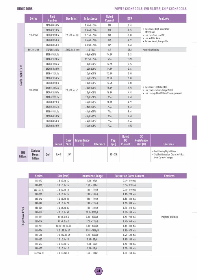
PCC-D126F
ETQP6F0R6BFA
12.5 x 12.5 x 6.0
0.58µH ±20% 19A 1.44• High Power, High Inductance
(MnFe Core)• Low Loss from Low RDC• Low Audible Noise• Surface Mount, Low profile
ETQP6F1R1BFA 1.06µH ±20% 16A 2.24
ETQP6F1R8BFA 1.71µH ±20% 14A 3.30
ETQP6F2R5BFA 2.45µH ±20% 12A 4.92
ETQP6F3R4BFA 3.32µH ±20% 10A 6.48
PCC-D1413H ETQPDH240DTV 14.7x13.2x13.1mm 24.0 (10A) 6.9 25.8 Magnetic shielding
PCC-F126F
ETQP6F0R8LFA
12.5 x 12.5 x 5.7
0.8µH ±30% 14.2A 2.24
• High Power (Isat 20A/100)• Thin Profile (5.7mm height)/SMD• Low Leakage Flux (EI type/Center gap core)
ETQP6F102HFA 10.2µH ±25% 6.5A 13.30
ETQP6F1R0SFA 1.0µH ±30% 14.2A 2.24
ETQP6F1R2HFA 1.2µH ±30% 14.2A 2.24
ETQP6F1R3LFA 1.3µH ±30% 12.5A 3.30
ETQP6F1R6SFA 1.6µH ±30% 12.5A 3.30
ETQP6F2R0HFA 2.0µH ±30% 12.5A 3.30
ETQP6F2R0LFA 2.0µH ±30% 10.8A 4.92
ETQP6F2R5SFA 2.5µH ±30% 10.8A 4.92
ETQP6F2R9LFA 2.9µH ±30% 9.3A 6.48
ETQP6F3R2HFA 3.2µH ±25% 10.8A 4.92
ETQP6F3R5SFA 3.5µH ±30% 9.3A 6.48
ETQP6F4R1LFA 4.1µH ±20% 7.9A 8.64
ETQP6F4R6HFA 4.6µH ±25% 9.3A 6.48
ETQP6F6R4HFA 6.4µH ±25% 7.9A 8.64
ETQP6F8R2HFA 8.2µH ±25% 7.2A 10.90
Series Size (mm) Inductance Range Saturation Rated Current Features
Chip
Cho
ke C
oils
ELL-4FG 3.8 x 3.8 x 1.2 1.00 ~ 47µH 0.29 ~ 1.90 mA
Magnetic shielding
ELL-4GG 3.8 x 3.8 x 1.4 1.20 ~ 100µH 0.25 ~ 1.90 mA
ELL-4LG--A 3.8 x 3.8 x 1.8 1.00 ~ 150µH 0.22 ~ 1.90 mA
ELL-6GG 6.0 x 6.0 x 1.6 1.00 ~ 100µH 0.30 - 2.50 mA
ELL-6PG 6.0 x 6.0 x 2.0 0.80 ~ 100µH 0.38 - 2.80 mA
ELL-6RH 6.0 x 6.0 x 2.8 1.00 ~ 220µH 0.20 - 3.00 mA
ELL-6SH 6.0 x 6.0 x 3.3 1.00 ~ 680µH 0.16 - 3.40 mA
ELL-6UH 6.0 x 6.0 x 5.0 10.0 ~ 1000µH 0.18 - 1.80 mA
ELL-8TP 8.0 x 8.0 x5.0 0.80 ~ 1000µH 0.25 - 9.00 mA
ELL-8UV 8.0 x 8.0 x6.5 1.30 ~ 220µH 0.66 - 5.40 mA
ELL-ATP 10.0 x 10.0 x 4.5x 1.00 ~ 1000µH 0.31 - 8.00 mA
ELL-ATV 10.0 x 10.0 x 4.5 1.50 ~ 1000µH 0.32 - 6.70 mA
ELL-CTV 12.0 x 12.0 x 4.5 1.20 ~ 1000µH 0.41 - 6.50 mA
ELL-VEG 3.0 x 3.0 x 1.0 0.68 ~ 22µH 0.33 - 1.80 mA
ELL-VFG 3.0 x 3.0 x 1.2 1.00 ~ 33µH 0.28 - 1.50 mA
ELL-VGG 3.0 x 3.0 x 1.5 1.00 ~ 47µH 0.27 - 1.80 mA
ELL-VGG--C 3.0 x 3.0 x1 .5 1.00 ~ 100µH 0.18 - 1.40 mA
SeriesCase Size
Impendance(Ω) Tolerance
Cap.(pF)
Rated DC
Current
DCResistance
Max (Ω) Features
EMI Filters
Surface Mount Filters
Coil ELK-E 1207 10 ~ 33K• For Filtering Digital Noise • Stable Attenuation Characteristics
Over Current Changes
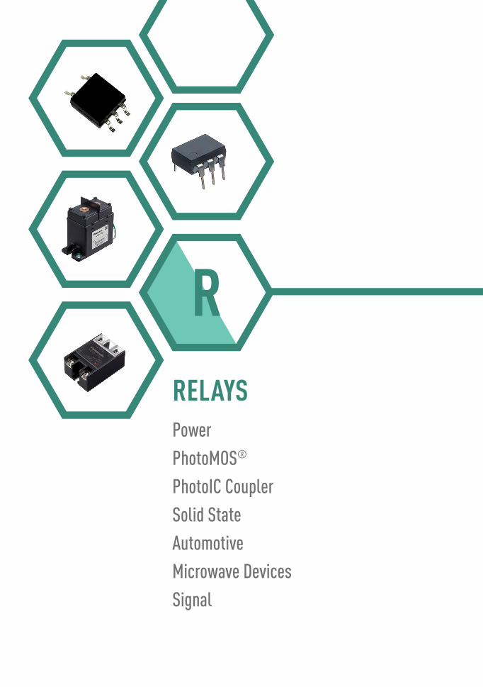
PowerPhotoMOS®
PhotoIC CouplerSolid StateAutomotiveMicrowave DevicesSignal
RELAYS
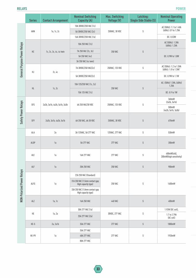
RELAYS POWER
33
Series Contact ArrangementNominal Switching
Capacity (A)Max. Switching
Voltage (V)Latching:
Single Side Stable (S)Nominal Operating
PowerGe
nera
l Pur
pose
Pow
er R
elay
s
AHN 1a, 1c, 2c
10A 30VDC/250 VAC (1c)
250VAC, 30 VDC S
AC (50Hz): 1.1 to 1.4VA(60Hz): 0.9 to 1.2VA5A 30VDC/250 VAC (2c)
16A 30VDC/250 VAC (1a) DC: 0.53W
HC 1c, 2c, 3c, 4c, 4c twin
10A 250 VAC (1c)
250 VAC S
AC (50Hz): 1.3VA(60Hz): 1.2VA
7A 250 VAC (2c, 3c)
DC: 0.9W to 1.0W5A 250 VAC (4c)
3A 250 VAC (4c twin)
HJ 2c, 4c
7A 30VDC/250 VAC(2c) 250VAC, 125 VDC S AC (50Hz): 1.2 to 1.5VA(60Hz): 1.0 to 1.3VA”
5A 30VDC/250 VAC(2c) DC: 0.9W to 1.1W
HL 1c, 2c
10A 125/250 VAC (1c, 2c)
250 VAC S
AC: (50Hz) 1.3VA, (60Hz) 1.2VA
15A 125 VAC (1c) DC: 0.9 to 1W
Safe
ty P
ower
Rel
ays
SFS 2a2b, 3a1b, 4a2b, 5a1b, 3a3b 6A 250 VAC/30 VDC 250VAC, 125 VDC S
360mW (2a2b, 3a1b)
500mW (4a2b, 5a1b, 3a3b)
SFY 2a2b, 3a1b, 4a2b, 5a1b 6A 250 VAC, 6A 30 VDC 250VAC, 30 VDC S 670mW
NON-
Pola
rized
Pow
er R
elay
s
ALA 2a 3A 125VAC, 5A 277 VAC 125VAC, 277 VAC S 530mW
ALDP 1a 5A 277 VAC 277 VAC S 200mW
ALE 1a 16A 277 VAC 277 VAC S 400mW(std), 200mW(high sensitivity)
ALF 1a 20A 250 VAC 250 VAC S 900mW
ALFG 1a
22A 250 VAC (Standard)
250 VAC S 1400mW31A 250 VAC (1.5mm contact gap
High capacity type)
33A 250 VAC (1.8mm contact gap High capacity type)
ALZ 1a, 1c 16A 250 VAC 440 VAC S 400mW
HE 1a, 2a
30A 277 VAC (1a)
30VDC, 277 VAC S
1.92W (DC coil),
25A 277 VAC (2a) 1.7 to 2.7VA (AC coil)
HE-S 2a, 2a1b 35A 277 VAC 277 VAC S 1880mW
HE-PV 1a
35A 277 VAC
277 VAC S 1920mW48A 277 VAC
80A 277 VAC
RELAYS
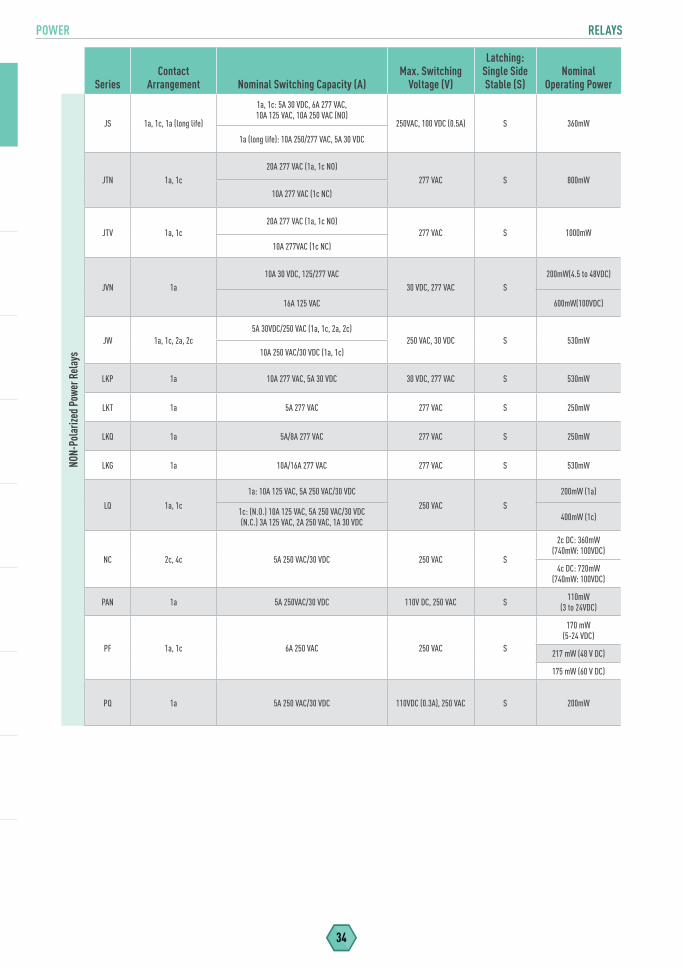
POWER RELAYS
34
SeriesContact
Arrangement Nominal Switching Capacity (A)Max. Switching
Voltage (V)
Latching: Single Side Stable (S)
Nominal Operating Power
NON-
Pola
rized
Pow
er R
elay
s
JS 1a, 1c, 1a (long life)
1a, 1c: 5A 30 VDC, 6A 277 VAC, 10A 125 VAC, 10A 250 VAC (NO)
250VAC, 100 VDC (0.5A) S 360mW
1a (long life): 10A 250/277 VAC, 5A 30 VDC
JTN 1a, 1c
20A 277 VAC (1a, 1c NO)
277 VAC S 800mW
10A 277 VAC (1c NC)
JTV 1a, 1c20A 277 VAC (1a, 1c NO)
277 VAC S 1000mW
10A 277VAC (1c NC)
JVN 1a10A 30 VDC, 125/277 VAC
30 VDC, 277 VAC S200mW(4.5 to 48VDC)
16A 125 VAC 600mW(100VDC)
JW 1a, 1c, 2a, 2c5A 30VDC/250 VAC (1a, 1c, 2a, 2c)
250 VAC, 30 VDC S 530mW10A 250 VAC/30 VDC (1a, 1c)
LKP 1a 10A 277 VAC, 5A 30 VDC 30 VDC, 277 VAC S 530mW
LKT 1a 5A 277 VAC 277 VAC S 250mW
LKQ 1a 5A/8A 277 VAC 277 VAC S 250mW
LKG 1a 10A/16A 277 VAC 277 VAC S 530mW
LQ 1a, 1c
1a: 10A 125 VAC, 5A 250 VAC/30 VDC
250 VAC S
200mW (1a)
1c: (N.O.) 10A 125 VAC, 5A 250 VAC/30 VDC(N.C.) 3A 125 VAC, 2A 250 VAC, 1A 30 VDC 400mW (1c)
NC 2c, 4c 5A 250 VAC/30 VDC 250 VAC S
2c DC: 360mW (740mW: 100VDC)
4c DC: 720mW (740mW: 100VDC)
PAN 1a 5A 250VAC/30 VDC 110V DC, 250 VAC S 110mW(3 to 24VDC)
PF 1a, 1c 6A 250 VAC 250 VAC S
170 mW(5-24 VDC)
217 mW (48 V DC)
175 mW (60 V DC)
PQ 1a 5A 250 VAC/30 VDC 110VDC (0.3A), 250 VAC S 200mW
RELAYS POWER
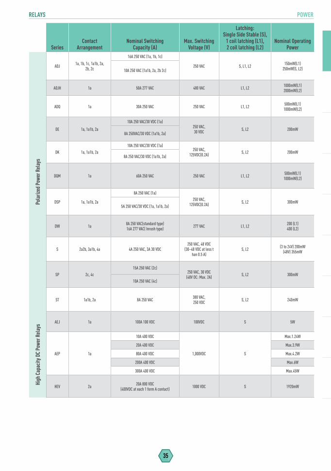
35
SeriesContact
ArrangementNominal Switching
Capacity (A)Max. Switching
Voltage (V)
Latching: Single Side Stable (S),
1 coil latching (L1), 2 coil latching (L2)
Nominal Operating Power
Pola
rized
Pow
er R
elay
s
ADJ 1a, 1b, 1c, 1a1b, 2a, 2b, 2c
16A 250 VAC (1a, 1b, 1c)
250 VAC S, L1, L2 150mW(L1) 250mW(S, L2)10A 250 VAC (1a1b, 2a, 2b 2c)
ADJH 1a 50A 277 VAC 480 VAC L1, L2 1000mW(L1) 2000mW(L2)
ADQ 1a 30A 250 VAC 250 VAC L1, L2 500mW(L1) 1000mW(L2)
DE 1a, 1a1b, 2a
10A 250 VAC/30 VDC (1a)250 VAC,30 VDC S, L2 200mW
8A 250VAC/30 VDC (1a1b, 2a)
DK 1a, 1a1b, 2a
10A 250 VAC/30 VDC (1a)250 VAC,
125VDC(0.2A) S, L2 200mW8A 250 VAC/30 VDC (1a1b, 2a)
DQM 1a 60A 250 VAC 250 VAC L1, L2 500mW(L1) 1000mW(L2)
DSP 1a, 1a1b, 2a
8A 250 VAC (1a)250 VAC,
125VDC(0.2A) S, L2 300mW5A 250 VAC/30 VDC (1a, 1a1b, 2a)
DW 1a 8A 250 VAC(standard type)16A 277 VAC( Inrush type) 277 VAC L1, L2 200 (L1)
400 (L2)
S 2a2b, 3a1b, 4a 4A 250 VAC, 3A 30 VDC250 VAC, 48 VDC
(30~48 VDC at less t han 0.5 A)
S, L2 (3 to 24V) 200mW(48V) 355mW
SP 2c, 4c
15A 250 VAC (2c)250 VAC, 30 VDC
(48V DC: Max. 2A) S, L2 300mW10A 250 VAC (4c)
ST 1a1b, 2a 8A 250 VAC 380 VAC,250 VDC S, L2 240mW
High
Cap
acity
DC
Powe
r Rel
ays AEJ 1a 100A 100 VDC 100VDC S 5W
AEP 1a
10A 400 VDC
1,000VDC S
Max.1.24W
20A 400 VDC Max.3.9W
80A 400 VDC Max.4.2W
200A 400 VDC Max.6W
300A 400 VDC Max.45W
HEV 2a 20A 800 VDC (400VDC at each 1 form A contact) 1000 VDC S 1920mW
PHOTOMOS RELAYS
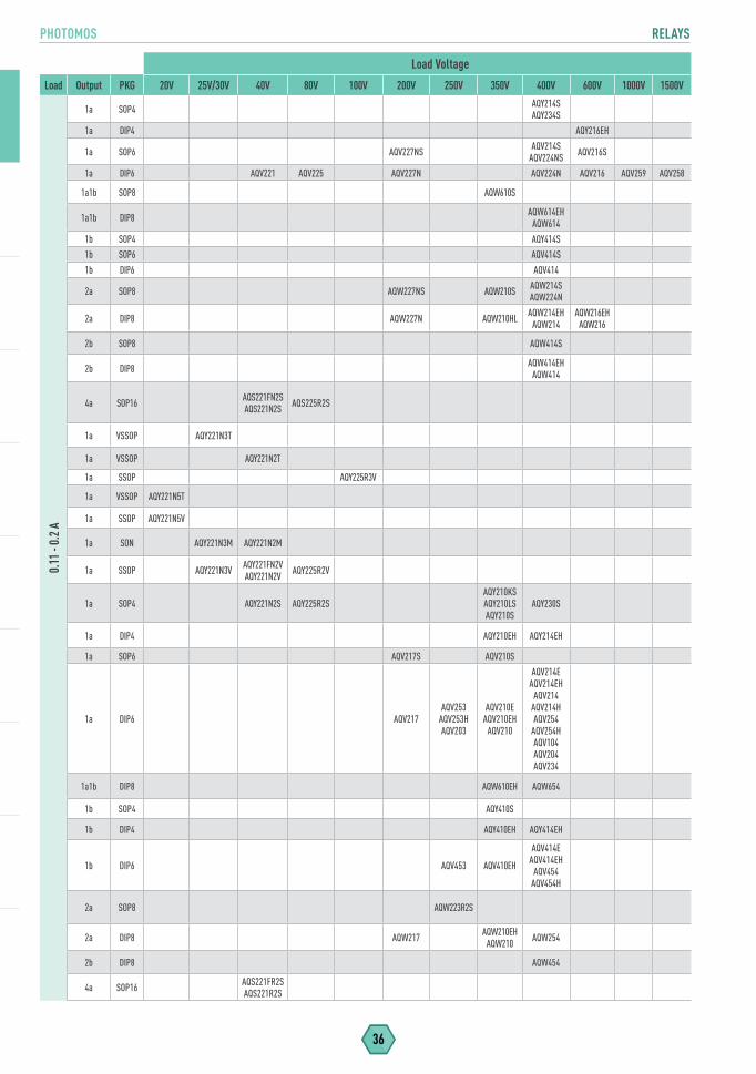
36
Load Voltage
Load Output PKG 20V 25V/30V 40V 80V 100V 200V 250V 350V 400V 600V 1000V 1500V
0.11
- 0.
2 A
1a SOP4 AQY214S AQY234S
1a DIP4 AQY216EH
1a SOP6 AQV227NS AQV214S AQV224NS AQV216S
1a DIP6 AQV221 AQV225 AQV227N AQV224N AQV216 AQV259 AQV258
1a1b SOP8 AQW610S
1a1b DIP8 AQW614EH AQW614
1b SOP4 AQY414S
1b SOP6 AQV414S
1b DIP6 AQV414
2a SOP8 AQW227NS AQW210S AQW214S AQW224N
2a DIP8 AQW227N AQW210HL AQW214EH AQW214
AQW216EH AQW216
2b SOP8 AQW414S
2b DIP8 AQW414EH AQW414
4a SOP16 AQS221FN2S AQS221N2S AQS225R2S
1a VSSOP AQY221N3T
1a VSSOP AQY221N2T
1a SSOP AQY225R3V
1a VSSOP AQY221N5T
1a SSOP AQY221N5V
1a SON AQY221N3M AQY221N2M
1a SSOP AQY221N3V AQY221FN2V AQY221N2V AQY225R2V
1a SOP4 AQY221N2S AQY225R2SAQY210KS AQY210LS AQY210S
AQY230S
1a DIP4 AQY210EH AQY214EH
1a SOP6 AQV217S AQV210S
1a DIP6 AQV217AQV253
AQV253H AQV203
AQV210E AQV210EH
AQV210
AQV214E AQV214EH
AQV214 AQV214H AQV254
AQV254H AQV104AQV204AQV234
1a1b DIP8 AQW610EH AQW654
1b SOP4 AQY410S
1b DIP4 AQY410EH AQY414EH
1b DIP6 AQV453 AQV410EH
AQV414E AQV414EH
AQV454 AQV454H
2a SOP8 AQW223R2S
2a DIP8 AQW217 AQW210EH AQW210 AQW254
2b DIP8 AQW454
4a SOP16 AQS221FR2S AQS221R2S
RELAYS PHOTOMOS
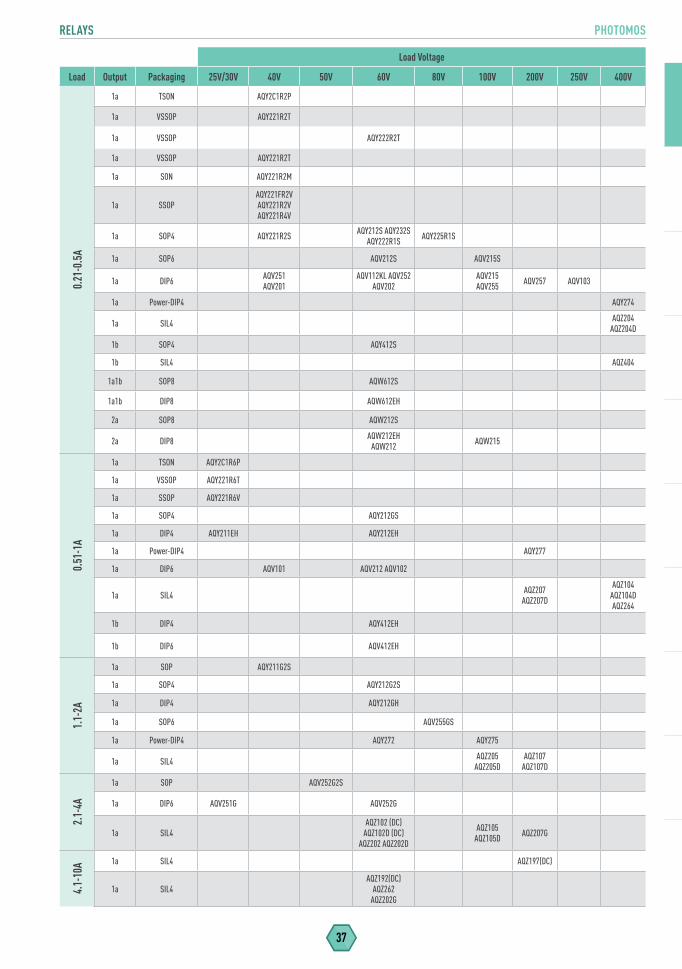
37
Load Voltage
Load Output Packaging 25V/30V 40V 50V 60V 80V 100V 200V 250V 400V0.
21-0
.5A
1a TSON AQY2C1R2P
1a VSSOP AQY221R2T
1a VSSOP AQY222R2T
1a VSSOP AQY221R2T
1a SON AQY221R2M
1a SSOPAQY221FR2V AQY221R2V AQY221R4V
1a SOP4 AQY221R2S AQY212S AQY232S AQY222R1S AQY225R1S
1a SOP6 AQV212S AQV215S
1a DIP6 AQV251 AQV201
AQV112KL AQV252 AQV202
AQV215 AQV255 AQV257 AQV103
1a Power-DIP4 AQY274
1a SIL4 AQZ204 AQZ204D
1b SOP4 AQY412S
1b SIL4 AQZ404
1a1b SOP8 AQW612S
1a1b DIP8 AQW612EH
2a SOP8 AQW212S
2a DIP8 AQW212EH AQW212 AQW215
0.51
-1A
1a TSON AQY2C1R6P
1a VSSOP AQY221R6T
1a SSOP AQY221R6V
1a SOP4 AQY212GS
1a DIP4 AQY211EH AQY212EH
1a Power-DIP4 AQY277
1a DIP6 AQV101 AQV212 AQV102
1a SIL4 AQZ207 AQZ207D
AQZ104 AQZ104D AQZ264
1b DIP4 AQY412EH
1b DIP6 AQV412EH
1.1-
2A
1a SOP AQY211G2S
1a SOP4 AQY212G2S
1a DIP4 AQY212GH
1a SOP6 AQV255GS
1a Power-DIP4 AQY272 AQY275
1a SIL4 AQZ205 AQZ205D
AQZ107 AQZ107D
2.1-
4A
1a SOP AQV252G2S
1a DIP6 AQV251G AQV252G
1a SIL4AQZ102 (DC)
AQZ102D (DC) AQZ202 AQZ202D
AQZ105 AQZ105D AQZ207G
4.1-
10A 1a SIL4 AQZ197(DC)
1a SIL4AQZ192(DC)
AQZ262AQZ202G
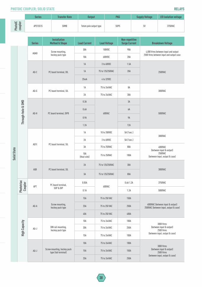
PHOTOIC COUPLER; SOLID STATE RELAYS
38
SeriesInstallation
Method & Shape Load Current Load VoltageNon-repetitive Surge Current Breakdown Voltage
Solid
Sta
te
Thro
ugh-
hole
& S
MD
AQAD Screw mounting, hockey puck type
30A 100VDC 90A4,000 Vrms between input and output
2500 Vrms between input and output case10A 600VDC 20A
AQ-C PC board terminal, DIL
1A 3 to 60VDC 1.5A
2500VAC1A 75 to 125/250VAC 20A
25mA 4 to 32VDC -
AQ-G PC board terminal, SIL1A 75 to 264VAC 8A
3000VAC2A 75 to 264VAC 30A
AQ-H PC board terminal, DIP8
0.3A
600VAC
3A
5000VAC
0.6A 6A
0.9A 9A
1.2A 12A
AQ1t PC board terminal, SIL
1A 10 to 200VDC 5A (1sec.)3000VAC
2A 3 to 60VDC 5A (1sec.)
3A 75 to 250VAC 80A 4000VAC(between input & output)
2500VAC(between input, output & case)
10A(Heat sink) 75 to 250VAC 100A
AQ8 PC board terminal, SIL
2A 75 to 125/250VAC 30A
3000VAC
3A 75 to 125/250VAC 80A
Phot
otria
c Co
uple
r
APT PC board terminal,SOP & DIP
0.05A600VAC
0.6A 1.2A 3750VAC
0.1A 1.2A 5000VAC
High
Cap
acity
AQ-A Screw mounting,hockey puck type
15A 75 to 250 VAC 150A
4000VAC (between input & output) 2500VAC (between input, output & case)25A 75 to 250 VAC 250A
40A 75 to 250 VAC 400A
AQ-J DIN rail mounting,hockey puck type
10A 75 to 264VAC 100A3000 Vrms
(between input & output)2500 Vrms
(between input, output & case)
20A 75 to 264VAC 250A
15A 75 to 264VAC 100A
AQ-J Screw mounting, hockey puck type (tab terminal)
10A 75 to 264VAC 100A3000 Vrms
(between input & output)2500 Vrms
(between input, output & case)
15A 75 to 264VAC 150A
25A 75 to 264VAC 250A
Series Transfer Rate Output PKG Supply Voltage I/O isolation voltagePh
otoI
C co
uple
r
APS1551S 50MB Totem pole output type SOP5 5V 3750VAC
RELAYS AUTOMOTIVE
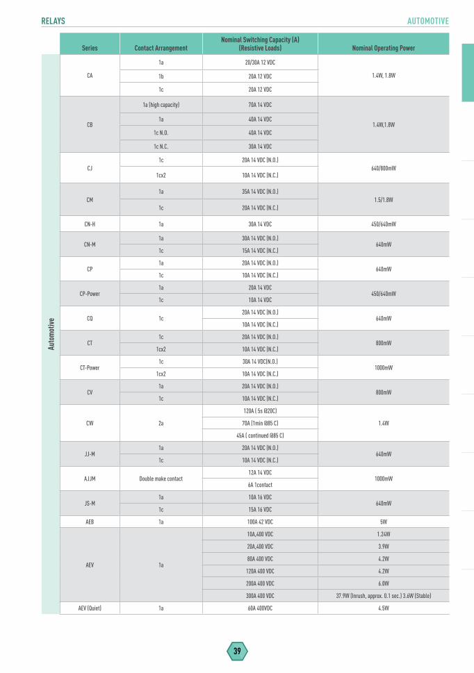
39
Series Contact ArrangementNominal Switching Capacity (A)
(Resistive Loads) Nominal Operating PowerAu
tom
otive
CA
1a 20/30A 12 VDC
1.4W, 1.8W1b 20A 12 VDC
1c 20A 12 VDC
CB
1a (high capacity) 70A 14 VDC
1.4W,1.8W1a 40A 14 VDC
1c N.O. 40A 14 VDC
1c N.C. 30A 14 VDC
CJ1c 20A 14 VDC (N.O.)
640/800mW1cx2 10A 14 VDC (N.C.)
CM1a 35A 14 VDC (N.O.)
1.5/1.8W1c 20A 14 VDC (N.C.)
CN-H 1a 30A 14 VDC 450/640mW
CN-M1a 30A 14 VDC (N.O.)
640mW1c 15A 14 VDC (N.C.)
CP1a 20A 14 VDC (N.O.)
640mW1c 10A 14 VDC (N.C.)
CP-Power1a 20A 14 VDC
450/640mW1c 10A 14 VDC
CQ 1c20A 14 VDC (N.O.)
640mW10A 14 VDC (N.C.)
CT1c 20A 14 VDC (N.O.)
800mW1cx2 10A 14 VDC (N.C.)
CT-Power1c 30A 14 VDC(N.O.)
1000mW1cx2 10A 14 VDC (N.C.)
CV1a 20A 14 VDC (N.O.)
800mW1c 10A 14 VDC (N.C.)
CW 2a
120A ( 5s @20C)
1.4W70A (1min @85 C)
45A ( continued @85 C)
JJ-M1a 20A 14 VDC (N.O.)
640mW1c 10A 14 VDC (N.C.)
AJJM Double make contact12A 14 VDC
1000mW6A 1contact
JS-M1a 10A 16 VDC
640mW1c 15A 16 VDC
AEB 1a 100A 42 VDC 5W
AEV 1a
10A,400 VDC 1.24W
20A,400 VDC 3.9W
80A 400 VDC 4.2W
120A 400 VDC 4.2W
200A 400 VDC 6.0W
300A 400 VDC 37.9W (Inrush, approx. 0.1 sec.) 3.6W (Stable)
AEV (Quiet) 1a 60A 400VDC 4.5W

40
MICROWAVE DEVICES RELAYS
SeriesContact
Arrangement
Maximum Switching
VoltageFrequency
Range (max) Contact Input Power
Latching: Single Side Stable(S)1 coil latching [L1],2 coil latching [L2]
Nominal Operating Power
Mic
rowa
ve D
evic
es
High
Freq
uenc
y Rel
ays
ARA 2c 30 VDC 1GHz 3W @ 1GHz S, L1, L2
S: 140mW (1.5 to 12V), 200mW (24V) 300mW (48V)
L1: 70mW (1.5 to 12V), 100mW (24V)
L2: 140mW (1.5 to 12V), 200mW (24V)
ARE 1c 30 VDC 2.6GHz 10W @ 2.6GHz S 200mW
ARJ 2c 30 VDC 8GHz 1W @ 5GHz S, L2 200mW (S), 150mW (L2)
ARN SPDT 6GHz 100W at 2Ghz S, L2 320mW (S), 400mW (L2)
ARS 1c 30 VDC 3GHz 10W @ 3GHz S, L1, L2 200mW (S, L1),400mW (L2)
Coax
ial S
witc
hes
ARD SPDT, Transfer, SP6T 30 VDC 100mA (indicator) 26.5GHz 12W @ 3GH S
840mW (SPDT/SP6T, Fail-safe, with indicator)
1540mW(Transfer, Fail-safe
with indicator)
ARV SPDT18GHz (PIN)
50W @ 3GH S 700mW26.5GHz (SMA)
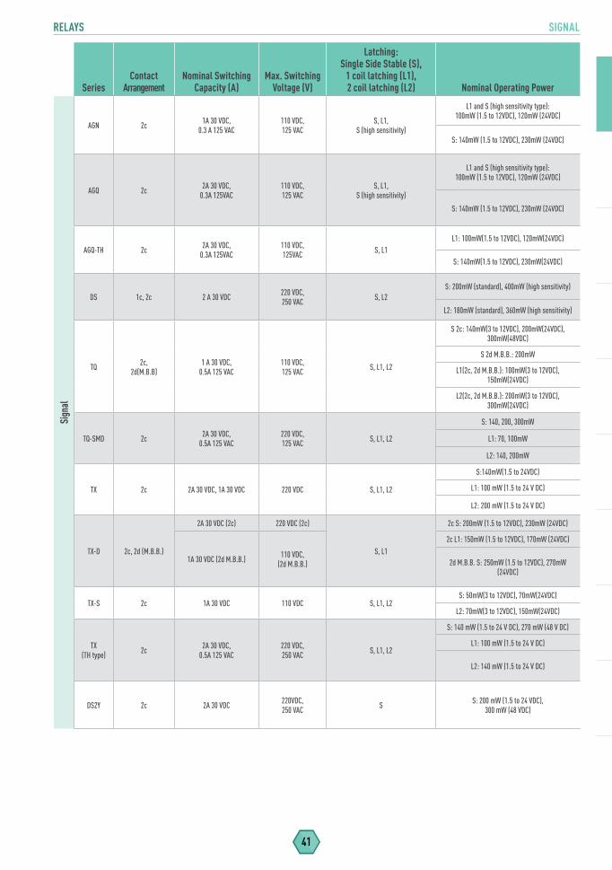
RELAYS SIGNAL
41
SeriesContact
ArrangementNominal Switching
Capacity (A)Max. Switching
Voltage (V)
Latching: Single Side Stable (S),
1 coil latching (L1),2 coil latching (L2) Nominal Operating Power
Sign
al
AGN 2c 1A 30 VDC, 0.3 A 125 VAC
110 VDC,125 VAC
S, L1, S (high sensitivity)
L1 and S (high sensitivity type): 100mW (1.5 to 12VDC), 120mW (24VDC)
S: 140mW (1.5 to 12VDC), 230mW (24VDC)
AGQ 2c 2A 30 VDC, 0.3A 125VAC
110 VDC,125 VAC
S, L1, S (high sensitivity)
L1 and S (high sensitivity type): 100mW (1.5 to 12VDC), 120mW (24VDC)
S: 140mW (1.5 to 12VDC), 230mW (24VDC)
AGQ-TH 2c 2A 30 VDC, 0.3A 125VAC
110 VDC, 125VAC S, L1
L1: 100mW(1.5 to 12VDC), 120mW(24VDC)
S: 140mW(1.5 to 12VDC), 230mW(24VDC)
DS 1c, 2c 2 A 30 VDC 220 VDC,250 VAC S, L2
S: 200mW (standard), 400mW (high sensitivity)
L2: 180mW (standard), 360mW (high sensitivity)
TQ 2c, 2d(M.B.B)
1 A 30 VDC, 0.5A 125 VAC
110 VDC,125 VAC S, L1, L2
S 2c: 140mW(3 to 12VDC), 200mW(24VDC), 300mW(48VDC)
S 2d M.B.B.: 200mW
L1(2c, 2d M.B.B.): 100mW(3 to 12VDC), 150mW(24VDC)
L2(2c, 2d M.B.B.): 200mW(3 to 12VDC), 300mW(24VDC)
TQ-SMD 2c 2A 30 VDC, 0.5A 125 VAC
220 VDC,125 VAC S, L1, L2
S: 140, 200, 300mW
L1: 70, 100mW
L2: 140, 200mW
TX 2c 2A 30 VDC, 1A 30 VDC 220 VDC S, L1, L2
S:140mW(1.5 to 24VDC)
L1: 100 mW (1.5 to 24 V DC)
L2: 200 mW (1.5 to 24 V DC)
TX-D 2c, 2d (M.B.B.)
2A 30 VDC (2c) 220 VDC (2c)
S, L1
2c S: 200mW (1.5 to 12VDC), 230mW (24VDC)
1A 30 VDC (2d M.B.B.) 110 VDC,(2d M.B.B.)
2c L1: 150mW (1.5 to 12VDC), 170mW (24VDC)
2d M.B.B. S: 250mW (1.5 to 12VDC), 270mW (24VDC)
TX-S 2c 1A 30 VDC 110 VDC S, L1, L2S: 50mW(3 to 12VDC), 70mW(24VDC)
L2: 70mW(3 to 12VDC), 150mW(24VDC)
TX(TH type) 2c 2A 30 VDC,
0.5A 125 VAC220 VDC,250 VAC S, L1, L2
S: 140 mW (1.5 to 24 V DC), 270 mW (48 V DC)
L1: 100 mW (1.5 to 24 V DC)
L2: 140 mW (1.5 to 24 V DC)
DS2Y 2c 2A 30 VDC 220VDC,250 VAC S S: 200 mW (1.5 to 24 VDC),
300 mW (48 VDC)
Narrow Pitch (Board to FPC)Narrow Pitch (Board to Board)FPC ConnectorsActive OpticalStacking for High Current
CONNECTORS

43
CONNECTORS NARROW PITCH
Board to FPC
Series S35 A35USA35US
w/Power Terminal
A35S A35P A4F A4US A4S F4S
Part Number (Socket) AXG1* AXG7** AXG7****J* AXE7** AXF5A** AXE3** AXE1** AXE5**
Part Number (Header) AXG2* AXG8** AXG8****J* AXE8** AXF6A** AXE4** AXE2** AXE6**
Mated Height (mm) 0.6 0.8 0.6 0.6 0.8 0.8 0.6 0.8 1.0 1.5 0.8 1.0 1 1.2
Socket (W) (mm) 1.7 2.2 2.2 2.5 2.5 3.0 2 2.2 3.6
Header (W) (mm) 1.5 1.8 1.8 2.0 2.0 2.4 1.8 2.2 2.6
Terminal Pitch (mm) 0.35 0.35 0.35 0.35 0.35 0.4 0.4 0.4
0-9 6
Num
ber o
f Con
tact
s
10 - 19 10, 16 12 10
12, 16 10,12,16 10,12,16 10,12,16 10, 12, 14, 16
10, 14,18 10 10, 12, 14,
16, 1810, 12,
1410,12, 14,16 10
20 - 29 20, 24 24 20,
24 20,24 20,24 20,24 20, 22, 24, 26 20,24 20 20 20, 22,
24, 26, 2820,
24, 2620,22,
24,26,28
30 - 39 30, 34 34 30,
34 30,34 30,34 30,34 30, 34, 36
30, 34,36 34 30, 32, 34,
36, 38 30, 32 30,32, 34,36 30
40 - 49 40, 44 44 40 40 40,44 40,44 40, 42, 44 40 40 40, 44 40, 44 40,42,
44,48 40
50 - 59 50, 54 50 50 50,54 50,54 50, 54 50 50, 54, 56 50, 54 50,54 50
60 - 69 60 60 60,64 60,64 60, 64 60 60 60 60, 64 60 60,6470 - 79 70 70 70 70 70 70 70 70
80 + 100, 120 80,100 80,100 80 80 80 80 80 80 80
Rated Current (contact) 0.3A 0.25A 0.3A 0.25A 0.5A 0.3A
Rated Voltage (AC/DC)
Insertion/Removal Life* 30X 50 X
30V60V
Board to FPC & Board to Board
Series P35S P4S P4S Shield Type P4 P4 w/ Soldering Terminal P5KF
Part Number (Socket) AXT1** AXT3** AXT3***F* AXK7** AXK7** AX5F**
Part Number (Header) AXT2** AXT4** AXT4** AXK8** AXK8** AXK6F**
Mated Height (mm) 1.5 1.5 2.0 2.5 3.0 1.5 1.5 2.0 2.5 3.0 3.5 1.5 2.0 2.5 3.0 3.5 1.5 2.0 2.5
Socket (W) (mm) 3.6 3.60 3.8 5.10 5.10 5.8
Header (W) (mm) 2.35 2.35 2.35 3.96 3.96 3.3
Terminal Pitch (mm) 0.4 0.4 0.4 0.4 0.4 0.5
Num
ber o
f Con
tact
s
10 - 19 10, 16 14 14 14 10 1210, 12, 14, 16,
18
10, 12, 14, 16,
1810, 12, 14, 16
20 - 2920,
22, 24, 26, 28
20, 22, 24, 26, 28
20 20 20, 22, 24,26
20, 24, 26
20, 24
20, 24
20, 24 20 20 20, 22,
24, 2620, 22, 24, 26 20, 22, 24
30 - 3930,
32, 34, 36, 38
30, 32, 34, 36, 38
30 30 30 38 30, 34 30 30 30 30 34 34 32 36 30,
32, 34 30, 34 30, 34
40 - 49 40 40, 44, 46 40 40 40, 44 40 40 40 40 40 40 40 40 40 40
50 - 59 50, 52 50, 54, 56 50 50, 54 50 50 50 50 50 50 50
60 - 69 60 60, 64 60 60 60, 64 60 60 60 60 60 60 60 6070 - 79 70 70 74 70 70 70 70 70 70 70 70
80+ 80, 90, 100
80, 90, 100
90, 100
80, 100 80, 100 80 80 80 80 80 80 80 80, 100 80, 100
Rated Current (contact) 0.25A 0.3A 0.3A 0.3A 0.3A 0.5A
Max Current 5A
Rated Voltage (AC/DC) 60V
Insertion/Removal Life* 50 X
*Inspection Connectors Available @ 3000X :: Ambient Operating Temperature: -55 ~ +85°C
4A
60V
CONNECTORS

NARROW PITCH, FPC CONNECTORS
44
Board to BoardSeries P5K P5KS
Part Number (Socket) AXK5** AXK5S**
Part Number (Header) AXk6** AXk6S**
Mated Height (mm) 3.0 3.5 4.0 4.5 5.0 5.5 6.0 6.5 7.0
Socket (W) (mm) 5.8 5.4
Header (W) (mm) 4.6 5.0
Terminal Pitch (mm) 0.5 0.5
Num
ber o
f Con
tact
s
20 - 29 20, 22 20, 22 20, 24 20, 24 20, 24 20, 24 20 20 20
30 - 39 30 30, 34 30, 34 30, 34, 36 30, 34 30, 34 30 30 30
40 - 49 40 40 40 40 40 40 40 40 40
50 - 59 50 50 50 50 50 50 50 50 50
60 - 69 60 60 60 60 60 60 60 60 60
70 - 79 70 70 70 70 70 70 70 70 70
80 + 80, 100, 120 80, 100, 120 80, 100 80, 100 80, 100 80, 100 80, 100 80, 100 80, 100
Rated Current (contact) 0.5A
Max Current 10A 16A
Rated Voltage (AC/DC) 60V
Insertion & Removal Life* 50X
FPC Connectors
Series Y3B Y3BW Y3BL Y3BC Y2B Y5B Y5BW Y4BH
Part Number AYF33**35 AYF33**65 AYF35**25 AYF36**35 AYF21**25 AYF53**35 AYF53**65T AYF42**35
Lock Structure Back Back Back Back Back Back Back
Mounting Height (mm) 0.9 0.6 1 0.9 1 1 1
Contact Pitch (mm) 0.3 0.3 0.3 0.2 0.5 0.5 0.4
Terminal Pitch (mm) 0.6 0.6 0.6 0.4 0.5 0.5 0.4
Dimension (W) (mm) 3.15 3.15 3.2 3.15 3.7 3.7 3.7
Num
ber o
f Con
tact
s
1 - 10 7, 8, 9 7 4, 5, 6, 8, 2, 3, 4, 6, 8
10 - 19 11, 13, 15, 17 11 11, 15 10, 12, 14, 16 10, 12, 14
20 - 29 21, 23, 25, 27 25 23, 27 25 23 24, 28 22, 26, 28
30 - 39 31, 33, 35, 37, 39 31, 39 31,39 31 30, 32, 34 30, 32, 38
40 - 49 41, 45 45 41 40, 42 40, 48 40, 50
50 - 59 51 51 51 51 50
60+ 61, 71 61
Compatibility w/FPC/FFC
FPC FPC FPC FPC FPC/FFC FPC FPC
Contact Structure Top & Bottom Top & Bottom Top & Bottom Top & Bottom Top & Bottom Top & Bottom Top & Bottom
Rated Current (Contact) 0.2A 0.2A 0.2A 0.2A 0.2A 0.5A 0.3A
Rated Voltage (AC/DC) 50 V
Insertion & Removal Life 30 X
*Inspection Connectors Available @ 3000X :: Ambient Operating Temperature: -55 ~ +85°C
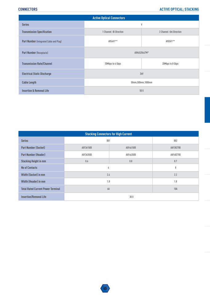
45
CONNECTORS ACTIVE OPTICAL; STACKING
Active Optical Connectors
Series V
Transmission Specification 1 Channel -Bi Direction 2 Channel -Uni Direction
Part Number (Integrated Cable and Plug) AYG4V1** AYG5V1**
Part Number (Receptacle) AXK6S20447M*
Transmission Rate/Channel 20Mbps to 6 Gbps 20Mbps to 8 Gbps
Electrical Static Discharge 2kV
Cable Length 50mm,500mm,1000mm
Insertion & Removal Life 50 X
Stacking Connectors for High Current
Series B01 B02
Part Number (Socket) AXF361500 AXF461500 AXF382700
Part Number (Header) AXF363500 AXF463500 AXF482700
Stacking Height in mm 0.6 0.8 0.7
No of Contacts 6 8
Width (Socket) in mm 2.4 2.2
Width (Header) in mm 1.8 1.8
Total Rated Current Power Terminal 6A 10A
Insertion/Removal Life 30 X
M
SD Cards
STORAGE MEDIA

47
STORAGE MEDIA SD CARDS
Series Form Factor Part number Capacity NANDOperating
TempData Transfer Rate (max) Read; Write Speed Class
FX SD
RP-SDFC51DA1 512 mb
SLC (60 k)
-40 - 85 C
22 MB/s; 20 MB/s Class 6
RP-SDFC02DA1 2 GB 22 MB/s; 20 MB/s Class 6
RP-SDFC04DA1 4 GB 90 MB/s; 40 MB/s Class 10/UHS-1 U1
RP-SDFC08DA1 8 GB 95 MB/s; 80 MB/s Class 10/UHS-1 U1
RP-SDF16GDA1 16 GB 95 MB/s; 80 MB/s Class 10/UHS-1 U1
P SD
RP-SDPC04DA1 4 GB
MLC (2k)
22 MB/s; 12 MB/s Class 4
RP-SDPC08DA1 8 GB 22 MB/s; 12 MB/s Class 4
RP-SDPC16DA1 16 GB 22 MB/s; 12 MB/s Class 4
GD SDRP-SDGD32DA1 32 GB 45 MB/s; 12 MB/s Class 10/UHS-1 U1
RP-SDGD64DA1 64 GB 45 MB/s; 12 MB/s Class 10/UHS-1 U1
SC MicroSD
RP-SMSC02DA1 2 GB
SLC (60 k)
22 MB/s; 20 MB/s Class 6
RP-SMSC04DA1 4 GB 90 MB/s; 40 MB/s Class 10/ UHS-1 U3
RP-SMSC08DA1 8 GB 90 MB/s; 40 MB/s Class 10/ UHS-1 U3
KC MicroSD
RP-SMKC04DA1 4 GB
MLC (2k)
45 MB/s ; 6 MB/s Class 2/UHS-1
RP-SMKC08DA1 8 GB 45 MB/s ; 6 MB/s Class 2/UHS-1
RP-SMKC16DA1 16 GB 45 MB/s ; 6 MB/s Class 2/UHS-1
MC eMMC 153 Ball
RP-SEMC08DA1 8 GB MLC (2k) / SLC-lite 260 MB/s ; 25 MB/s -
RP-SEMC16DA1 16 GB 260 MB/s ; 22 MB/s -
RP-SEMC32DA1 32 GB 260 MB/s ; 45 MB/s -
QE SD
RP-SDQE04DA1 4 GB
SLC (60 k)-Lite
-25 - 85 C
65 MB/s; 65 MB/s Class 10/UHS-1 U1
RP-SDQE08DA1 8 GB 65 MB/s; 65 MB/s Class 10/UHS-1 U2
RP-SDQE16DA1 16 GB 65 MB/s; 65 MB/s Class 10/UHS-1 U3
ME SD
RP-SDME04DA1 4 GB
MLC (2k) (2k)
90 MB/s; 25 MB/s Class 10/UHS-1 U1
RP-SDME08DA1 8 GB 90 MB/s; 25 MB/s Class 10/UHS-1 U1
RP-SDME16DA1 16 GB 90 MB/s; 45 MB/s Class 10/UHS-1 U3
RP-SDME32DA1 32 GB 90 MB/s; 45 MB/s Class 10/UHS-1 U3
UE SDRP-SDUE64DA1 64 GB 95 MB/s; 90 MB/s Class 10/UHS-1 U3
RP-SDUE12DA1 128 GB 95 MB/s; 90 MB/s Class 10/UHS-1 U3
XE SD RP-SDXE25DA1 256 GB 280 MB/s ; 90 MB/s Class 10/UHS-1 U3/ UHS-2 U3
PE MicroSD
RP-SMPE04DA1 4 GB
SLC (60 k)-Lite
22 MB/s; 20 MB/s Class 6
RP-SMPE08DA1 8 GB 45 MB/s; 35 MB/s Class 10/UHS-1 U1
RP-SMPE16DA1 16 GB 90 MB/s; 45 MB/s Class 10/UHS-1 U3
RP-SMPE32DA1 32 GB 90 MB/s; 45 MB/s Class 10/UHS-1 U3
LE MicroSD
RP-SMLE04DA1 4 GB
MLC (2k)
90 MB/s; 25 MB/s Class 10/UHS-1 U1
RP-SMLE08DA1 8 GB 90 MB/s; 25 MB/s Class 10/UHS-1 U1
RP-SMLE16DA1 16 GB 90 MB/s; 45 MB/s Class 10/UHS-1 U3
RP-SMLE32DA1 32 GB 90 MB/s; 45 MB/s Class 10/UHS-1 U3
TE MicroSD RP-SMTE64DA1 64 GB 95 MB/s; 90 MB/s Class 10/UHS-1 U3
TT MicroSDRP-SMTT32DA1 32 GB
-40 - 85 C95 MB/s; 90 MB/s Class 10/UHS-1 U3
RP-SMTT64DA1 64 GB 95 MB/s; 90 MB/s Class 10/UHS-1 U3
MF SD
RP-SDMF08DA1 8 GB
TLC (500) -25 - 85 C
20 MB/s ; 5 MB/s Class 4
RP-SDMF16DA1 16 GB 80 MB/s ; 10 MB/s Class 10/UHS-1 U1
RP-SDMF32DA1 32 GB 80 MB/s ; 10 MB/s Class 10/UHS-1 U1
RP-SDMF64DA1 64 GB 80 MB/s ; 10 MB/s Class 10/UHS-1 U1
LF MicroSD
RP-SMLF08DA1 8 GB 20 MB/s ; 5 MB/s Class 4
RP-SMLF16DA1 16 GB 80 MB/s ; 10 MB/s Class 10/UHS-1 U1
RP-SMLF32DA1 32 GB 80 MB/s ; 10 MB/s Class 10/UHS-1 U1
RP-SMLF64DA1 64 GB 80 MB/s ; 10 MB/s Class 10/UHS-1 U1
STORAGE MEDIA
Passive InfraredInfrared Array Grid-EYE®
Air Pressure
SENSORS

49
SENSORS PASSIVE INFRARED
SeriesCurrentUsage
OperatingVoltage(VDC)
CircuitStability
Time Range Lens Color Output Detection AngleProfile (mm)*
LensDiameter (mm)
Pass
ive I
nfra
red
PaPI
Rs
EKMB 1µA, 2µA, 6µA 2.3-4.0
1µA/2µA - 25s (typ.)
5m, 12m White, Black, Pearl White Digital
5m:94° (H), 82° (V) Standard
Detection Type
5m:14.4 Standard Detection Type
5m:9.5 Standard Detection Type
6µA - 30s(max.)
12m:102° (H), 92° (V) Long Detection Type
12m:20.2 Long Detection Type
12m:20.7 Long Detection Type
12m, 6m, 3m: 40° (H), 105°(V)
Wall Installation Type
12m, 6m, 3m: 20.2 Wall installation type
12m, 6m, 3m : 20.7 Wall installation type
2.2m : 44° (H), 44°(V) Saturn Lens, Slight Motion
2.2m : 17.2 Saturn Lens
(Slight Motion & Standard Motion)
2.2m : 14.1 Saturn Lens
(Slight Motion & Standard Motion)2.2m : 90° (H), 90°(V)
Saturn Lens, Standard Motion
EKMC 170µA 3.0-6.0 30s (max.) 5m, 12m White, Black, Pearl White Digital
5m:94° (H), 82° (V) Standard
Detection Type
5m:14.4 Standard Detection Type
5m:9.5 Standard Detection Type
12m:102° (H), 92° (V) Long Detection Type
12m:20.2 Long Detection Type
12m:20.7 Long Detection Type
12m, 6m, 3m: 40° (H), 105°(V)
Wall Installation Type
12m, 6m, 3m: 20.2 Wall installation type
12m, 6m, 3m : 20.7 Wall installation type
2.2m : 44° (H), 44°(V) Saturn Lens, Slight Motion
2.2m : 17.2 Saturn Lens
(Slight Motion & Standard Motion)
2.2m : 14.1 Saturn Lens
(Slight Motion & Standard Motion)2.2m : 90° (H), 90°(V)
Saturn Lens, Standard Motion
NaPi
On
AMN2 170µA 4.5-5.5 45s (max.) 2m, 5m, 10m Black, White Analog
Slight motion:91° (H), 91° (V)
Slight motion:15.2
Slight motion:12.7
5m:100° (H), 82° (V)
5m:14.5
5m:9.5
Spot detection:38° (H), 22° (V)
Spot detection:15.1
Spot detection:8.9
10m:110° (H), 93° (V)
10m:18.52
10m:17.4
AMN3 170µA 3.0-6.0 30s (max.) 2m, 5m, 10m Black, White Digital
Slight motion:91° (H), 91° (V)
Slight motion:15.2
Slight motion:12.7
5m:100° (H), 82° (V)
5m:14.5
5m:9.5
Spot detection:38° (H), 22° (V)
Spot detection:15.1
Spot detection:8.9
10m:110° (H), 93° (V)
10m:18.52
10m:17.4
*Profile measured from top of sensor to base (does not include pin length)
SENSORS
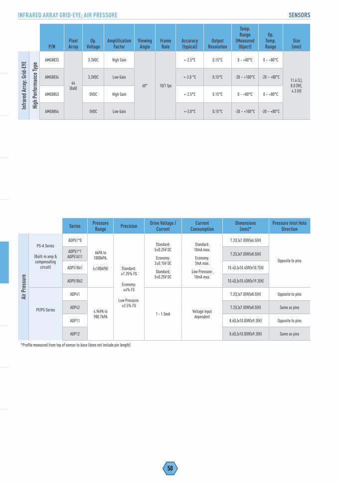
INFRARED ARRAY GRID-EYE; AIR PRESSURE SENSORS
50
Series Pressure Range Precision Drive Voltage /
CurrentCurrent
ConsumptionDimensions
(mm)*Pressure Inlet Hole
Direction
Air P
ress
ure
PS-A Series
(Built-in amp & compensating
circuit)
ADP51*0
6kPA to 1000kPA,
(±100kPA) Standard:±1.25% FS
Economy:±4% FS
Low Pressure:±2.5% FS
Standard: 5±0.25V DC
Economy: 3±0.15V DC
Standard: 5±0.25V DC
Standard: 10mA max.
Economy: 3mA max.
Low Pressure: 10mA max.
7.2(L)x7.0(W)x6.5(H)
Opposite to pins
ADP51*1ADP51A11 7.2(L)x7.0(W)x8.5(H)
ADP51B61 10.4(L)x10.4(W)x10.7(H)
ADP51B62 10.4(L)x10.4(W)x19.3(H)
PF/PS Series
ADP41
4.9kPA to 980.7kPA 1 - 1.5mA Voltage input
dependent
7.2(L)x7.0(W)x8.5(H) Opposite to pins
ADP42 7.2(L)x7.0(W)x8.5(H) Same as pins
ADP11 8.6(L)x10.0(W)x9.3(H) Opposite to pins
ADP12 8.6(L)x10.0(W)x9.3(H) Same as pins
*Profile measured from top of sensor to base (does not include pin length)
P/NPixel Array
Op.Voltage
Amplification Factor
Viewing Angle
Frame Rate
Accuracy (typical)
Output Resolution
Temp. Range
(Measured Object)
Op.Temp. Range
Size(mm)
Infra
red A
rray
: Grid
-EYE
High
Per
form
ance
Type
AMG8833
64(8x8)
3.3VDC High Gain
60° 10/1 fps
+-2.5°C 0.15°C 0 ~ +80°C 0 ~ +80°C
11.6 (L), 8.0 (W), 4.3 (H)
AMG8834 3.3VDC Low Gain +-3.0 °C 0.15°C -20 ~ +100°C -20 ~ +80°C
AMG8853 5VDC High Gain +-2.5°C 0.15°C 0 ~ +80°C 0 ~ +80°C
AMG8854 5VDC Low Gain +-3.0°C 0.15°C -20 ~ +100°C -20 ~ +80°C

DatasheetShortcut
Introducing The New Datasheet Shortcut Tool
Enter A Part Number...Get A Datasheet. It’s That Simple!
Enter A Part Number...Get A Datasheet. It’s That Simple!

DiodesASSPMOSFETs
SEMICONDUCTORS
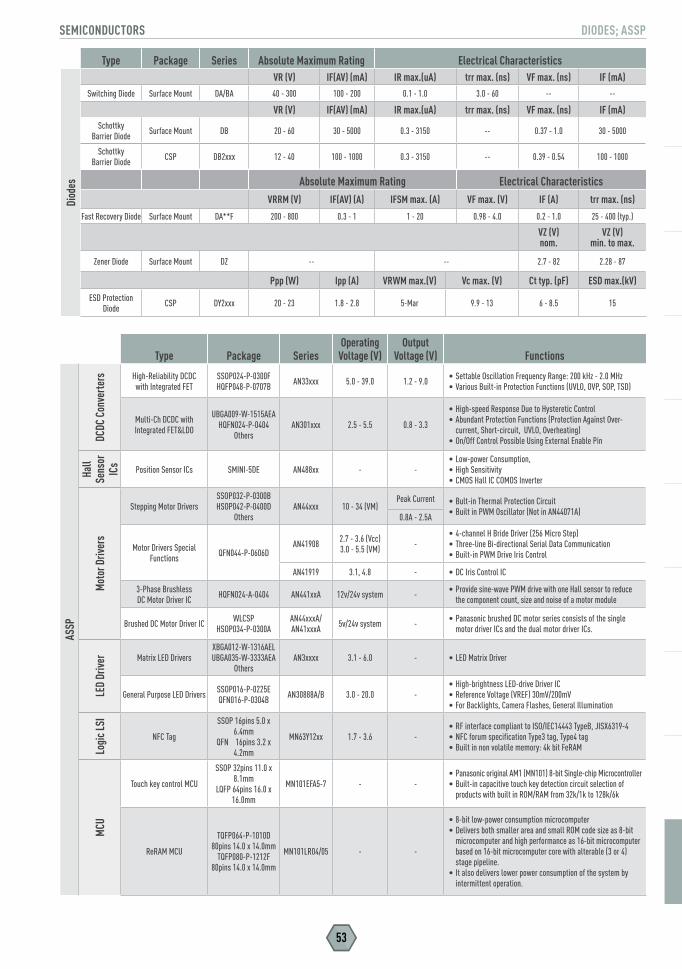
53
SEMICONDUCTORS DIODES; ASSP
Type Package Series Absolute Maximum Rating Electrical CharacteristicsDi
odes
VR (V) IF(AV) (mA) IR max.(uA) trr max. (ns) VF max. (ns) IF (mA)
Switching Diode Surface Mount DA/BA 40 - 300 100 - 200 0.1 - 1.0 3.0 - 60 -- --
VR (V) IF(AV) (mA) IR max.(uA) trr max. (ns) VF max. (ns) IF (mA)Schottky
Barrier Diode Surface Mount DB 20 - 60 30 - 5000 0.3 - 3150 -- 0.37 - 1.0 30 - 5000
Schottky Barrier Diode CSP DB2xxx 12 - 40 100 - 1000 0.3 - 3150 -- 0.39 - 0.54 100 - 1000
Absolute Maximum Rating Electrical CharacteristicsVRRM (V) IF(AV) (A) IFSM max. (A) VF max. (V) IF (A) trr max. (ns)
Fast Recovery Diode Surface Mount DA**F 200 - 800 0.3 - 1 1 - 20 0.98 - 4.0 0.2 - 1.0 25 - 400 (typ.)
VZ (V) nom.
VZ (V)min. to max.
Zener Diode Surface Mount DZ -- -- 2.7 - 82 2.28 - 87
Ppp (W) Ipp (A) VRWM max.(V) Vc max. (V) Ct typ. (pF) ESD max.(kV)
ESD Protection Diode CSP DY2xxx 20 - 23 1.8 - 2.8 5-Mar 9.9 - 13 6 - 8.5 15
Type Package SeriesOperating
Voltage (V)Output
Voltage (V) Functions
ASSP
DCDC
Con
verte
rs High-Reliability DCDC with Integrated FET
SSOP024-P-0300FHQFP048-P-0707B AN33xxx 5.0 - 39.0 1.2 - 9.0 • Settable Oscillation Frequency Range: 200 kHz - 2.0 MHz
• Various Built-in Protection Functions (UVLO, OVP, SOP, TSD)
Multi-Ch DCDC with Integrated FET&LDO
UBGA009-W-1515AEAHQFN024-P-0404
OthersAN301xxx 2.5 - 5.5 0.8 - 3.3
• High-speed Response Due to Hysteretic Control• Abundant Protection Functions (Protection Against Over-
current, Short-circuit, UVLO, Overheating)• On/Off Control Possible Using External Enable Pin
Hall
Sens
or
ICs Position Sensor ICs SMINI-5DE AN488xx - -
• Low-power Consumption,• High Sensitivity• CMOS Hall IC COMOS Inverter
Mot
or D
river
s
Stepping Motor DriversSSOP032-P-0300BHSOP042-P-0400D
OthersAN44xxx 10 - 34 (VM)
Peak Current • Bult-in Thermal Protection Circuit• Built in PWM Oscillator (Not in AN44071A)0.8A - 2.5A
Motor Drivers Special Functions QFN044-P-0606D
AN41908 2.7 - 3.6 (Vcc)3.0 - 5.5 (VM) -
• 4-channel H Bride Driver (256 Micro Step)• Three-line Bi-directional Serial Data Communication• Built-in PWM Drive Iris Control
AN41919 3.1, 4.8 - • DC Iris Control IC
3-Phase Brushless DC Motor Driver IC HQFN024-A-0404 AN441xxA 12v/24v system - • Provide sine-wave PWM drive with one Hall sensor to reduce
the component count, size and noise of a motor module
Brushed DC Motor Driver IC WLCSPHSOP034-P-0300A
AN44xxxA/AN41xxxA 5v/24v system - • Panasonic brushed DC motor series consists of the single
motor driver ICs and the dual motor driver ICs.
LED
Drive
r Matrix LED DriversXBGA012-W-1316AELUBGA035-W-3333AEA
OthersAN3xxxx 3.1 - 6.0 - • LED Matrix Driver
General Purpose LED Drivers SSOP016-P-0225EQFN016-P-0304B AN30888A/B 3.0 - 20.0 -
• High-brightness LED-drive Driver IC• Reference Voltage (VREF) 30mV/200mV• For Backlights, Camera Flashes, General Illumination
Logi
c LSI
NFC Tag
SSOP 16pins 5.0 x 6.4mm
QFN 16pins 3.2 x 4.2mm
MN63Y12xx 1.7 - 3.6 -• RF interface compliant to ISO/IEC14443 TypeB, JISX6319-4• NFC forum specification Type3 tag, Type4 tag• Built in non volatile memory: 4k bit FeRAM
MCU
Touch key control MCU
SSOP 32pins 11.0 x 8.1mm
LQFP 64pins 16.0 x 16.0mm
MN101EFA5-7 - -• Panasonic original AM1 (MN101) 8-bit Single-chip Microcontroller• Built-in capacitive touch key detection circuit selection of
products with built in ROM/RAM from 32k/1k to 128k/6k
ReRAM MCU
TQFP064-P-1010D 80pins 14.0 x 14.0mm
TQFP080-P-1212F 80pins 14.0 x 14.0mm
MN101LR04/05 - -
• 8-bit low-power consumption microcomputer• Delivers both smaller area and small ROM code size as 8-bit
microcomputer and high performance as 16-bit microcomputer based on 16-bit microcomputer core with alterable (3 or 4) stage pipeline.
• It also delivers lower power consumption of the system by intermittent operation.
SEMICONDUCTORS
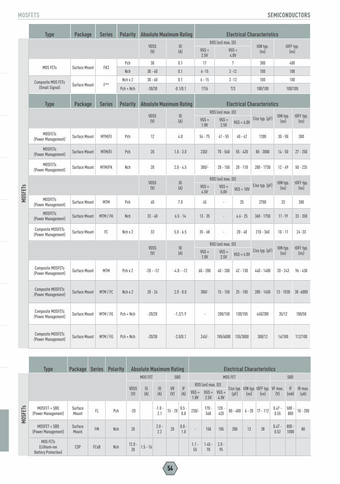
MOSFETS SEMICONDUCTORS
54
Type Package Series Polarity Absolute Maximum Rating Electrical Characteristics
MOS
FETs
VDSS(V)
ID(A)
RDS (on) max. (Ω)tON typ.
(ns)tOFF typ.
(ns)VGS = 2.5V
VGS = 4.0V
MOS FETs Surface Mount FK3Pch 30 0.1 17 7 300 400
Nch 30 - 60 0.1 6 -15 3 -12 100 100
Composite MOS FETs (Small Signal) Surface Mount F**
Nch x 2 30 - 60 0.1 6 - 15 3 -12 100 100
Pch + Nch -30/30 -0.1/0.1 17/6 7/3 100/100 100/100
Type Package Series Polarity Absolute Maximum Rating Electrical Characteristics
VDSS(V)
ID(A)
RDS (on) max. (Ω)Ciss typ. (pF) tON typ.
(ns)tOFF typ.
(ns)VGS = 1.8V
VGS = 2.5V VGS = 4.0V
MOSFETs(Power Management) Surface Mount MTM/FJ Pch 12 4.0 54 - 75 41 - 55 40 - 42 1200 30 - 50 300
MOSFETs(Power Management) Surface Mount MTM/FJ Pch 20 1.0 - 3.0 230/- 70 - 560 55 - 420 80 - 3000 14 - 50 27 - 250
MOSFETs(Power Management) Surface Mount MTM/FK Nch 20 2.0 - 4.5 300/- 28 - 150 28 - 110 280 - 1730 12 - 49 50 - 225
VDSS(V)
ID(A)
RDS (on) max. (Ω)Ciss typ. (pF) tON typ.
(ns)tOFF typ.
(ns)VGS = 4.5V
VGS = 5.0V VGS = 10V
MOSFETs(Power Management) Surface Mount MTM Pch 40 7.0 45 - 25 2700 33 300
MOSFETs(Power Management) Surface Mount MTM / FK Nch 33 - 40 6.5 - 14 13 - 35 - 4.6 - 25 360 - 1750 11 -19 33 - 350
Composite MOSFETs (Power Management) Surface Mount FC Nch x 2 33 5.0 - 6.5 35 - 68 - 20 - 40 210 - 360 10 - 11 24 -33
VDSS(V)
ID(A)
RDS (on) max. (Ω)Ciss typ. (pF) tON typ.
(ns)tOFF typ.
(ns)VGS = 1.8V
VGS = 2.5V VGS = 4.0V
Composite MOSFETs (Power Management) Surface Mount MTM Pch x 2 -20 - -12 -4.8 - -12 60 - 280 40 - 200 42 - 130 440 - 1400 20 - 243 96 - 430
Composite MOSFETs (Power Management) Surface Mount MTM / FC Nch x 2 20 - 24 2.0 - 8.0 300/- 15 - 150 25 - 105 280 - 1450 13 - 1030 38 -6000
Composite MOSFETs (Power Management) Surface Mount MTM / FG Pch + Nch -20/20 -1.2/1.9 - 200/150 130/105 440/280 35/12 100/50
Composite MOSFETs (Power Management) Surface Mount MTM / FG Pch + Nch -20/30 -2.0/0.1 245/- 185/6000 135/3000 300/12 14/100 112/100
Type Package Series Polarity Absolute Maximum Rating Electrical Characteristics
MOS
FETs
MOS FET SBD MOS FET SBD
VDSS(V)
IS(A)
ID(A)
VR(V)
IF(A)
RDS (on) max. (Ω)Ciss typ.
(pF)tON typ.
(ns)tOFF typ.
(ns)VF max.
(V)IF
(mA)IR max.
(uA)VGS = 1.8V
VGS = 2.5V
VGS = 4.0V
MOSFET + SBD(Power Management)
Surface Mount FL Pch -20 -1.0 -
2.1 15 - 20 0.5 - 0.8 230/- 170 -
560120 - 420 80 - 400 6 - 35 17 - 112 0.47 -
0.55500 - 800 10 - 200
MOSFET + SBD(Power Management)
Surface Mount FM Nch 20 2.0 -
2.2 20 0.8 - 1.0 - 150 105 280 13 38 0.47 -
0.52800 - 1000 80
MOS FETs (Lithium-ion
Battery Protection) CSP FCxB Nch 12.0 -
20 1.5 - 16 1.1 - 55
1.45 - 70
2.0 - 95

GaN Technology Is Here. So Long Silicon!Panasonic Can Unlock The Full Performance
Of Gallium Nitride Power Technology
Visit http://bit.ly/2neh6eq today for details
GaN Technology Overview
GaN Material Information
X-GaNTM Transistors
Benefits and Applications

ThermistorsZNR Surge AbsorbersVaristorsEMI FiltersFuse ResistorsESD Suppressors
CIRCUIT PROTECTION
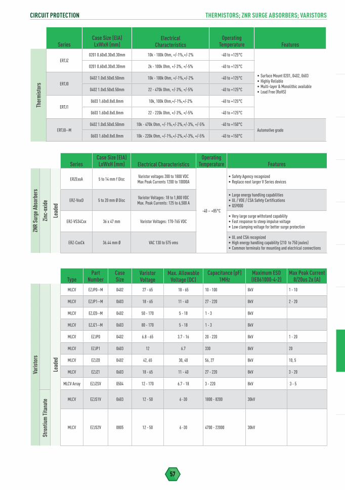
57
CIRCUIT PROTECTION THERMISTORS; ZNR SURGE ABSORBERS; VARISTORS
SeriesCase Size (EIA)LxWxH (mm) Electrical Characteristics
OperatingTemperature Features
ZNR
Surg
e Abs
orbe
rs
Zinc-
oxid
e
Lead
ed
ERZExxA 5 to 14 mm f Disc Varistor voltages 200 to 1800 VDC Max Peak Currents 1200 to 10000A
-40 ~ +85°C
• Safety Agency recognized• Replace next larger V Series devices
ERZ-VxxD 5 to 20 mm Ø Disc Varistor Voltages: 18 to 1,800 VDCMax. Peak Currents: 125 to 6,500 A
• Large energy handling capabilities • UL / VDE / CSA Safety Certifications• QS9000
ERZ-VS34Cxx 36 x 47 mm Varistor Voltages: 170-765 VDC• Very large surge withstand capability• Fast response to steep impulse voltage• Low clamping voltage for better surge protection
ERZ-CxxCk 36.44 mm Ø VAC 130 to 575 vms• UL and CSA recognized• High energy handling capability (210 to 750 joules) • Common terminals for mounting and electrical connections
SeriesCase Size (EIA)LxWxH (mm)
Electrical
CharacteristicsOperating
Temperature FeaturesTh
erm
isto
rs
ERTJZ0201 0.60x0.30x0.30mm 10k - 100k Ohm, +/-1%,+/-2% -40 to +125°C
• Surface Mount 0201, 0402, 0603• Highly Reliable• Multi-layer & Monolithic available• Lead Free (RoHS)
0201 0.60x0.30x0.30mm 2k - 100k Ohm, +/-3%, +/-5% -40 to +125°C
ERTJ00402 1.0x0.50x0.50mm 10k - 100k Ohm, +/-1%,+/-2% -40 to +125°C
0402 1.0x0.50x0.50mm 22 - 470k Ohm, +/-3%, +/-5% -40 to +125°C
ERTJ10603 1.60x0.8x0.8mm 10k, 100k Ohm,+/-1%,+/-2% -40 to +125°C
0603 1.60x0.8x0.8mm 22 - 220k Ohm, +/-3%, +/-5% -40 to +125°C
ERTJ0--M0402 1.0x0.50x0.50mm 10k - 470k Ohm, +/-1%,+/-2%,+/-3%, +/-5% -40 to +150°C
Automotive grade0603 1.60x0.8x0.8mm 10k - 220k Ohm, +/-1%,+/-2%,+/-3%, +/-5% -40 to +150°C
CIRCUIT PROTECTION TypePart
NumberCase Size
Varistor Voltage
Max. Allowable Voltage (DC)
Capacitance (pF) 1MHz
Maximum ESD (IE061000-4-2)
Max Peak Current 8/20us 2x (A)
Varis
tors
Lead
ed
MLCV EZJP0--M 0402 27 - 65 18 - 65 10 - 100 8kV 1 - 10
MLCV EZJP1--M 0603 18 - 65 11 - 40 27 - 220 8kV 2 - 20
MLCV EZJZ0--M 0402 50 - 170 5 - 18 1 - 3 8kV
MLCV EZJZ1--M 0603 80 - 170 5 - 18 1 - 3 8kV
MLCV EZJP0 0402 6.8 - 65 3.7 - 16 20 - 220 8kV 1 - 20
MLCV EZJP1 0603 12 6.7 330 8kV 20
MLCV EZJZ0 0402 42, 65 30, 40 56, 27 8kV 10, 5
MLCV EZJZ1 0603 18 - 65 11 - 40 27 - 220 8kV 3 - 20
MLCV Array EZJZSV 0504 12 - 170 6.7 - 18 3 - 220 8kV 3 - 5
MLCV EZJS1V 0603 12 - 50 6 -30 1800 - 8200 30kV
MLCV EZJS2V 0805 12 - 50 6 -30 4700 - 22000 30kV
Stro
ntiu
m Ti
tana
te
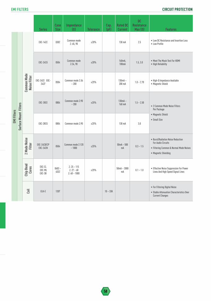
EMI FILTERS CIRCUIT PROTECTION
58
SeriesCase Size
Impendance(Ω) Tolerance
Cap.(pF)
Rated DC Current
DCResistance
Max (Ω) Features
EMI F
ilter
sSu
rface
Mou
nt F
ilter
s
Com
mon
Mod
eNo
ise F
ilter
EXC-14CE 0302 Common modeZ: 65, 90 ±20% 130 mA 2.5 • Low DC Resistance and Insertion Loss
• Low Profile
EXC-24CG 0504 Common mode Z:24, 90 ±20% 160mA,
100mA 1.5, 3.0 • Meet The Mask-Test For HDMI• High Reliability
EXC-24CE EXC-24CF 0504 Common mode Z:36
~ 200 ±25% 130mA ~ 200 mA 1.0 ~ 2.70 • High-Q Impedance Available
• Magnetic Shield
EXC-28CE 0804 Common mode Z:90 ~ 200 ±25% 130mA ~
160 mA 1.5 ~ 2.50• 2 Common Mode Noise Filters
Per Package
• Magnetic Shield
• Small SizeEXC-28CG 0804 Common mode Z:90 ±25% 130 mA 3.0
2 M
ode N
oise
Fi
lter
EXC-24CB/CP EXC-24CN 0504 Common mode Z:120
~ 1000 ±25% 50mA ~ 500 mA 0.3 ~ 1.5
• Burst/Radiation Noise Reduction For Audio Circuits
• Filtering Common & Normal Mode Noises
• Magnetic Shielding
Chip
Bea
d Co
res EXC-CL
EXC-ML EXC-3B
0603 ~ 4532
Z: 25 ~ 115Z: 27 ~ 68
Z: 60 ~ 1000±25% 50mA ~ 2000
mA 0.1 ~ 1.0 • Effective Noise Suppression For Power Lines And High Speed Signal Lines
Coil
ELK-E 1207 10 ~ 33K
• For Filtering Digital Noise
• Stable Attenuation Characteristics Over Current Changes
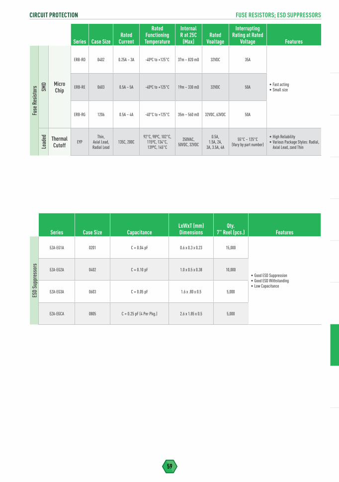
59
CIRCUIT PROTECTION FUSE RESISTORS; ESD SUPPRESSORS
Series Case SizeRated
Current
Rated Functioning Temperature
Internal R at 25C
(Max)Rated
Voaltage
Interrupting Rating at Rated
Voltage FeaturesFu
se R
esis
tors SM
D Micro Chip
ERB-RD 0402 0.25A ~ 3A -40ºC to +125°C 37m ~ 820 mΩ 32VDC 35A
• Fast acting• Small sizeERB-RE 0603 0.5A ~ 5A -40ºC to +125°C 19m ~ 330 mΩ 32VDC 50A
ERB-RG 1206 0.5A ~ 4A -40°C to +125°C 35m ~ 560 mΩ 32VDC, 63VDC 50A
Lead
ed Thermal Cutoff
EYPThin,
Axial Lead, Radial Lead
135C, 200C92°C, 98ºC, 102°C,
115ºC, 134°C, 139ºC, 145°C
250VAC, 50VDC, 32VDC
0.5A, 1.5A, 2A,
3A, 3.5A, 4A
55°C ~ 125°C (Vary by part number)
• High Reliability• Various Package Styles: Radial,
Axial Lead, zand Thin
Series Case Size CapacitanceLxWxT (mm)Dimensions
Qty.7” Reel (pcs.) Features
ESD
Supp
ress
ors
EZA-EG1A 0201 C = 0.04 pF 0.6 x 0.3 x 0.23 15,000
• Good ESD Suppression• Good ESD Withstanding• Low Capacitance
EZA-EG2A 0402 C = 0.10 pF 1.0 x 0.5 x 0.38 10,000
EZA-EG3A 0603 C = 0.05 pF 1.6 x .80 x 0.5 5,000
EZA-EGCA 0805 C = 0.25 pF (4 Per Pkg.) 2.6 x 1.85 x 0.5 5,000
Pyrolytic Graphite Sheet (PGS)Soft PGSSemi-Sealing Material (SSM)Graphite-PADNASBIS Insulating Sheet
THERMAL MANAGEMENT
TM

61
THERMAL MANAGEMENT PYROLYTIC GRAPHITE SHEET (PGS)
THERMAL MANAGEMENT
Type
PGS Thickness
(µm) Part Number
StandardSheet Size
(mm2)
PGS Thermal Conductivity (a-b plane ) (W/(m·K))
PGS Electrical Conductivity
(S/cm)
PGS Density (g/cm3)
PGS Extensional
Strength(MPa)
Pyro
lytic
Gra
phite
She
et (P
GS)
S Ty
pe Graphite Sheet Only
100 µm
EYG-S091210 90 × 115 mm2
700 W/(m·K) 10000 S/cm 0.85 g/cm3 19.6 MPaEYG-S121810 115 × 180 mm2
EYG-S182310 180 × 230 mm2
70 µm
EYG-S091207 90 × 115 mm2
1000 W/(m·K) 10000 S/cm 1.21 g/cm3 20.0 MPaEYG-S121807 115 × 180 mm2
EYG-S182307 180 × 230 mm2
50 μm
EYG-S091205 90 × 115 mm2
1300 W/(m·K) 10000 S/cm 1.70 g/cm3 20.0 MPaEYG-S121805 115 × 180 mm2
EYG-S182305 180 × 230 mm2
40 μm
EYG-S091204 90 × 115 mm2
1350 (m·K) 10000 S/cm 1.80 g/cm3 25.0 MPaEYG-S121804 115 × 180 mm2
EYG-S182304 180 × 230 mm2
25 µmEYG-S091203 90 × 115 mm2
1600 W/(m·K) 20000 S/cm 1.90 g/cm3 30.0 MPaEYG-S121803 115 × 180 mm2
A-A
Type Graphite Sheet
With 30 µm Acrylic Adhesive
70 µmEYG-A091207A 90 × 115 mm2
1000 W/(m·K) 10000 S/cm 1.21 g/cm3 20.0 MPaEYG-A121807A 115 × 180 mm2
50 µmEYG-A091205A 90 × 115 mm2
1300 W/(m·K) 10000 S/cm 1.70 g/cm3 20.0 MPaEYG-A121805A 115 × 180 mm2
40 µmEYG-A091204A 90 × 115 mm2
1350 W/(m·K) 10000 S/cm 1.80 g/cm3 25.0 MPaEYG-A121804A 115 × 180 mm2
25 µmEYG-A091203A 90 × 115 mm2
1600 W/(m·K) 20000 S/cm 1.90 g/cm3 30.0 MPaEYG-A121803A 115 × 180 mm2
17 µmEYG-A091202A 90 × 115 mm2
1750 W/(m·K) 20000 S/cm 2.10 g/cm3 40.0 MPaEYG-A121802A 115 × 180 mm2
10 µmEYG-A091201A 90 × 115 mm2
1950 W/(m·K) 20000 S/cm 2.13 g/cm3 40.0 MPaEYG-A121801A 115 × 180 mm2
A-F T
ype Graphite Sheet
With 6 µm Acrylic Adhesive
50 µmEYG-A091205F 90 × 115 mm2
1300 W/(m·K) 10000 S/cm 1.70 g/cm3 20.0 MPaEYG-A121805F 115 × 180 mm2
40 µmEYG-A091204F 90 × 115 mm2
1350 W/(m·K) 10000 S/cm 1.80 g/cm3 25.0 MPaEYG-A121804F 115 × 180 mm2
17 µmEYG-A091202F 90 × 115 mm2
1850 W/(m·K) 20000 S/cm 2.10 g/cm3 40.0 MPaEYG-A121802F 115 × 180 mm2
10 µmEYG-A091201F 90 × 115 mm2
1950 W/(m·K) 20000 S/cm 2.13 g/cm3 40.0 MPaEYG-A121801F 115 × 180 mm2
A-M
Typ
e
Graphite SheetWith 10 µm
Acrylic Adhesive
70 µmEYG-A091207M 90 x 115 mm2
1000 W/(m·K) 10000 S/cm 1.21 g/cm3 22.0 MPaEYG-A121807M 115 x 180 mm2
50 µmEYG-A091205M 90 × 115 mm2
1300 W/(m·K) 10000 S/cm 1.70 g/cm3 20.0 MPaEYG-A121805M 115 × 180 mm2
40 µmEYG-A091204M 90 × 115 mm2
1350 W/(m·K) 10000 S/cm 1.80 g/cm3 25.0 MPaEYG-A121804M 115 × 180 mm2
25 µmEYG-A091203M 90 × 115 mm2
1600 W/(m·K) 20000 S/cm 1.90 g/cm3 30.0 MPaEYG-A121803M 115 × 180 mm2
17 µmEYG-A091202M 90 × 115 mm2
1750 W/(m·K) 20000 S/cm 2.10 g/cm3 40.0 MPaEYG-A121802M 115 × 180 mm2
10 µmEYG-A091201M 90 × 115 mm2
1950 W/(m·K) 20000 S/cm 2.13 g/cm3 40.0 MPaEYG-A121801M 115 × 180 mm2

PYROLYTIC GRAPHITE SHEET (PGS) THERMAL MANAGEMENT
62
Type
PGS Thickness
(µm) Part Number
StandardSheet Size
(mm2)
PGS Thermal Conductivity (a-b plane ) (W/(m·K))
PGS Electrical Conductivity
(S/cm)
PGS Density (g/cm3)
PGS Extensional
Strength(MPa)
Pyro
lytic
Gra
phite
She
et (P
GS)
A-DF
Type
Graphite SheetWith 6 µm
Acrylic Adhesive And 10 µm
Polyester Tape
50 µmEYG-A091205DF 90 × 115 mm2
1300 W/(m·K) 10000 S/cm 1.70 g/cm3 20.0 MPaEYG-A121805DF 115 × 180 mm2
40 µmEYG-A091204DF 90 × 115 mm2
1350 W/(m·K) 10000 S/cm 1.80 g/cm3 25.0 MPaEYG-A121804DF 115 × 180 mm2
17 µmEYG-A091202DF 90 × 115 mm2
1850 W/(m·K) 20000 S/cm 2.10 g/cm3 40.0 MPaEYG-A121802DF 115 × 180 mm2
10 µmEYG-A091201DF 90 × 115 mm2
1950 W/(m·K) 20000 S/cm 2.13 g/cm3 40.0 MPaEYG-A121801DF 115 × 180 mm2
A-PA
Type
Graphite SheetWith 30 µm
Acrylic Adhesive And 30 µm
Polyester Tape
70 µmEYG-A091207PA 90 × 115 mm2
1000 W/(m·K) 10000 S/cm 1.21 g/cm3 22.0 MPaEYG-A121807PA 115 × 180 mm2
50 µmEYG-A091205PA 90 × 115 mm2
1300 W/(m·K) 10000 S/cm 1.70 g/cm3 20.0 MPaEYG-A121805PA 115 × 180 mm2
40 µmEYG-A091204PA 90 × 115 mm2
1350 W/(m·K) 10000 S/cm 1.80 g/cm3 25.0 MPaEYG-A121804PA 115 × 180 mm2
25 µmEYG-A091203PA 90 × 115 mm2
1600 W/(m·K) 20000 S/cm 1.90 g/cm3 30.0 MPaEYG-A121803PA 115 × 180 mm2
17 µmEYG-A091202PA 90 × 115 mm2
1750 W/(m·K) 20000 S/cm 2.10 g/cm3 40.0 MPaEYG-A121802PA 115 × 180 mm2
10 µmEYG-A091201PA 90 × 115 mm2
1950 W/(m·K) 20000 S/cm 2.13 g/cm3 40.0 MPaEYG-A121801PA 115 × 180 mm2
A-PM
Type
Graphite SheetWith 10 µm
Acrylic Adhesive And 30 µm
Polyester Tape
70 µmEYG-A091207PM 90 × 115 mm2
1000 W/(m·K) 10000 S/cm 1.21 g/cm3 22.0 MPaEYG-A121807PM 115 × 180 mm2
50 µmEYG-A091205PM 90 × 115 mm2
1300 W/(m·K) 10000 S/cm 1.70 g/cm3 20.0 MPaEYG-A121805PM 115 × 180 mm2
40 µmEYG-A091204PM 90 × 115 mm2
1350 W/(m·K) 10000 S/cm 1.80 g/cm3 25.0 MPaEYG-A121804PM 115 × 180 mm2
25 µmEYG-A091203PM 90 × 115 mm2
1600 W/(m·K) 20000 S/cm 1.90 g/cm3 30.0 MPaEYG-A121803PM 115 × 180 mm2
17 µmEYG-A091202PM 90 × 115 mm2
1750 W/(m·K) 20000 S/cm 2.10 g/cm3 40.0 MPaEYG-A121802PM 115 × 180 mm2
10 µm EYG-A091201PM 90 × 115 mm2
1950 W/(m·K) 20000 S/cm 2.13 g/cm3 40.0 MPaEYG-A121801PM 115 × 180 mm2
A-DM
Type
Graphite SheetWith 10 µm
Acrylic Adhesive And 10 µm
Polyester Tape
70 µmEYG-A091207DM 90 × 115 mm2
1000 W/(m·K) 10000 S/cm 1.21 g/cm3 22.0 MPaEYG-A121807DM 115 × 180 mm2
50 µmEYG-A091205DM 90 × 115 mm2
1300 W/(m·K) 10000 S/cm 1.70 g/cm3 20.0 MPaEYG-A121805DM 115 × 180 mm2
40 µmEYG-A091204DM 90 × 115 mm2
1350 W/(m·K) 10000 S/cm 1.80 g/cm3 25.0 MPaEYG-A121804DM 115 × 180 mm2
25 µmEYG-A091203DM 90 × 115 mm2
1600 W/(m·K) 20000 S/cm 1.90 g/cm3 30.0 MPaEYG-A121803DM 115 × 180 mm2
17 µmEYG-A091202DM 90 × 115 mm2
1750 W/(m·K) 20000 S/cm 2.10 g/cm3 40.0 MPaEYG-A121802DM 115 × 180 mm2
10 µmEYG-A091201DM 90 × 115 mm2
1950 W/(m·K) 20000 S/cm 2.13 g/cm3 40.0 MPaEYG-A121801DM 115 × 180 mm2

63
THERMAL MANAGEMENT PYROLYTIC GRAPHITE SHEET (PGS)
Type
PGSThickness
(µm) Part Number
StandardSheet Size
(mm2)
PGS Thermal Conductivity (a-b plane ) (W/(m·K))
PGS Electrical Conductivity
(S/cm)
PGS Density (g/cm3)
PGS Extensional
Strength(MPa)
Pyro
lytic
Gra
phite
She
et (P
GS)
A-V
Type Graphite Sheet With
18 µm High Heat Resistant Acrylic Adhesive (150°C)
70 µmEYG-A091207V 90 x 115 mm2
1000 W/(m·K) 10000 S/cm 1.21 g/cm3 22.0 MPaEYG-A121807V 115 x 180 mm2
50 µmEYG-A091205V 90×115 mm2
1300 W/(m·K) 10000 S/cm 1.70 g/cm3 20.0 MPaEYG-A121805V 115×180 mm2
40 µmEYG-A091204V 90×115 mm2
1350 W/(m·K) 10000 S/cm 1.80 g/cm3 25.0 MPaEYG-A121804V 115×180 mm2
25 µmEYG-A091203V 90 x 115 mm2
1600 W/(m·K) 20000 S/cm 1.90 g/cm3 30.0 MPaEYG-A121803V 115 x 180 mm2
17 µmEYG-A091202V 90 x 115 mm2
1750 W/(m·K) 20000 S/cm 2.10 g/cm3 40.0 MPaEYG-A121802V 115 x 180 mm2
10 µmEYG-A091201V 90×115 mm2
1950 W/(m·K) 20000 S/cm 2.13 g/cm3 40.0 MPaEYG-A121801V 115×180 mm2
A-RV
Type
Graphite Sheet With 18 µm High Heat Resistant Acrylic Adhesive (150°C)
And 13 µm PEEK Tape
70 µmEYG-A091207RV 90 x 115 mm2
1000 W/(m·K) 10000 S/cm 1.21 g/cm3 22.0 MPaEYG-A121807RV 115 x 180 mm2
50 µmEYG-A091205RV 90×115 mm2
1300 W/(m·K) 10000 S/cm 1.70 g/cm3 20.0 MPaEYG-A121805RV 115×180 mm2
40 µmEYG-A091204RV 90×115 mm2
1350 W/(m·K) 10000 S/cm 1.80 g/cm3 25.0 MPaEYG-A121804RV 115×180 mm2
25 µmEYG-A091203RV 90 x 115 mm2
1600 W/(m·K) 20000 S/cm 1.90 g/cm3 30.0 MPaEYG-A121803RV 115 x 180 mm2
17 µmEYG-A091202RV 90 x 115 mm2
1750 W/(m·K) 20000 S/cm 2.10 g/cm3 40.0 MPaEYG-A121802RV 115 x 180 mm2
10 µmEYG-A091201RV 90×115 mm2
1950 W/(m·K) 20000 S/cm 2.13 g/cm3 40.0 MPaEYG-A121801RV 115×180 mm2
A-KV
Type
Graphite Sheet With 18 µm
High Heat Resistant Acrylic Adhesive
(150°C) And 18 µm Polymide Tape
70 µmEYG-A091207KV 90 x 115 mm2
1000 W/(m·K) 10000 S/cm 1.21 g/cm3 22.0 MPaEYG-A121807KV 115 x 180 mm2
50 µmEYG-A091205KV 90×115 mm2
1300 W/(m·K) 10000 S/cm 1.70 g/cm3 20.0 MPaEYG-A121805KV 115×180 mm2
40 µmEYG-A091204KV 90×115 mm2
1350 W/(m·K) 10000 S/cm 1.80 g/cm3 25.0 MPaEYG-A121804KV 115×180 mm2
25 µmEYG-A091203KV 90 x 11 mm2
1600 W/(m·K) 20000 S/cm 1.90 g/cm3 30.0 MPaEYG-A121803KV 115 x 180 mm2
17 µmEYG-A091202KV 90 x 115 mm2
1750 W/(m·K) 20000 S/cm 2.10 g/cm3 40.0 MPaEYG-A121802KV 115 x 180 mm2
10 µmEYG-A091201KV 90×115 mm2
1950 W/(m·K) 20000 S/cm 2.13 g/cm3 40.0 MPaEYG-A121801KV 115×18 mm2
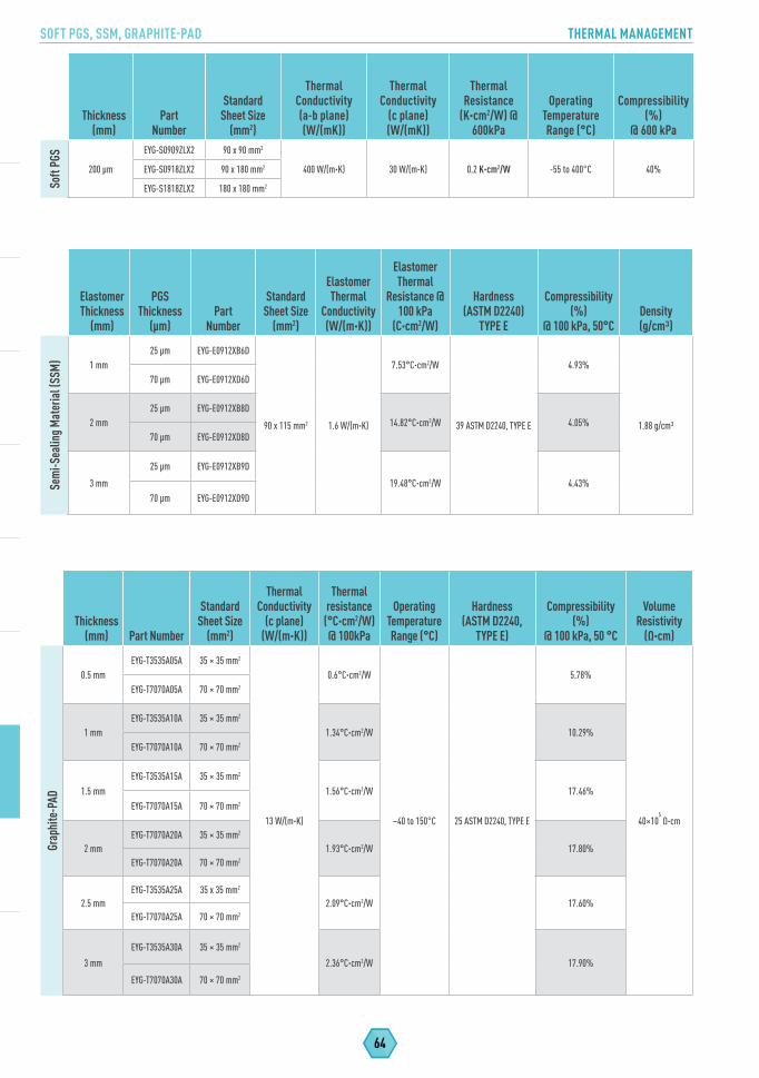
SOFT PGS, SSM, GRAPHITE-PAD THERMAL MANAGEMENT
64
Thickness (mm) Part Number
StandardSheet Size
(mm2)
Thermal Conductivity
(c plane) (W/(m·K))
Thermal resistance
(°C·cm2/W) @ 100kPa
Operating Temperature Range (°C)
Hardness(ASTM D2240,
TYPE E)
Compressibility (%)
@ 100 kPa, 50 °C
Volume Resistivity
(Ω·cm)
Grap
hite
-PAD
0.5 mmEYG-T3535A05A 35 × 35 mm2
13 W/(m·K)
0.6°C·cm2/W
−40 to 150°C 25 ASTM D2240, TYPE E
5.78%
40×105 Ω·cm
EYG-T7070A05A 70 × 70 mm2
1 mmEYG-T3535A10A 35 × 35 mm2
1.34°C·cm2/W 10.29%EYG-T7070A10A 70 × 70 mm2
1.5 mmEYG-T3535A15A 35 × 35 mm2
1.56°C·cm2/W 17.46%EYG-T7070A15A 70 × 70 mm2
2 mmEYG-T7070A20A 35 × 35 mm2
1.93°C·cm2/W 17.80%EYG-T7070A20A 70 × 70 mm2
2.5 mmEYG-T3535A25A 35 x 35 mm2
2.09°C·cm2/W 17.60%EYG-T7070A25A 70 × 70 mm2
3 mm
EYG-T3535A30A 35 × 35 mm2
2.36°C·cm2/W 17.90%
EYG-T7070A30A 70 × 70 mm2
Elastomer Thickness
(mm)
PGS Thickness
(µm)Part
Number
StandardSheet Size
(mm2)
Elastomer Thermal
Conductivity (W/(m·K))
Elastomer Thermal
Resistance @ 100 kPa
(C·cm2/W)
Hardness(ASTM D2240)
TYPE E
Compressibility (%)
@ 100 kPa, 50°CDensity(g/cm3)
Sem
i-Sea
ling M
ater
ial (
SSM
) 1 mm25 µm EYG-E0912XB6D
90 x 115 mm2 1.6 W/(m·K)
7.53°C·cm2/W
39 ASTM D2240, TYPE E
4.93%
1.88 g/cm3
70 µm EYG-E0912XD6D
2 mm25 µm EYG-E0912XB8D
14.82°C·cm2/W 4.05%70 µm EYG-E0912XD8D
3 mm
25 µm EYG-E0912XB9D
19.48°C·cm2/W 4.43%70 µm EYG-E0912XD9D
Thickness (mm)
Part Number
Standard Sheet Size
(mm2)
Thermal Conductivity (a-b plane)(W/(mK))
Thermal Conductivity
(c plane)(W/(mK))
Thermal Resistance
(K·cm2/W) @ 600kPa
Operating Temperature Range (°C)
Compressibility (%)
@ 600 kPa
Soft
PGS
200 µm
EYG-S0909ZLX2 90 x 90 mm2
400 W/(m·K) 30 W/(m·K) 0.2 K·cm2/W -55 to 400°C 40%EYG-S0918ZLX2 90 x 180 mm2
EYG-S1818ZLX2 180 x 180 mm2
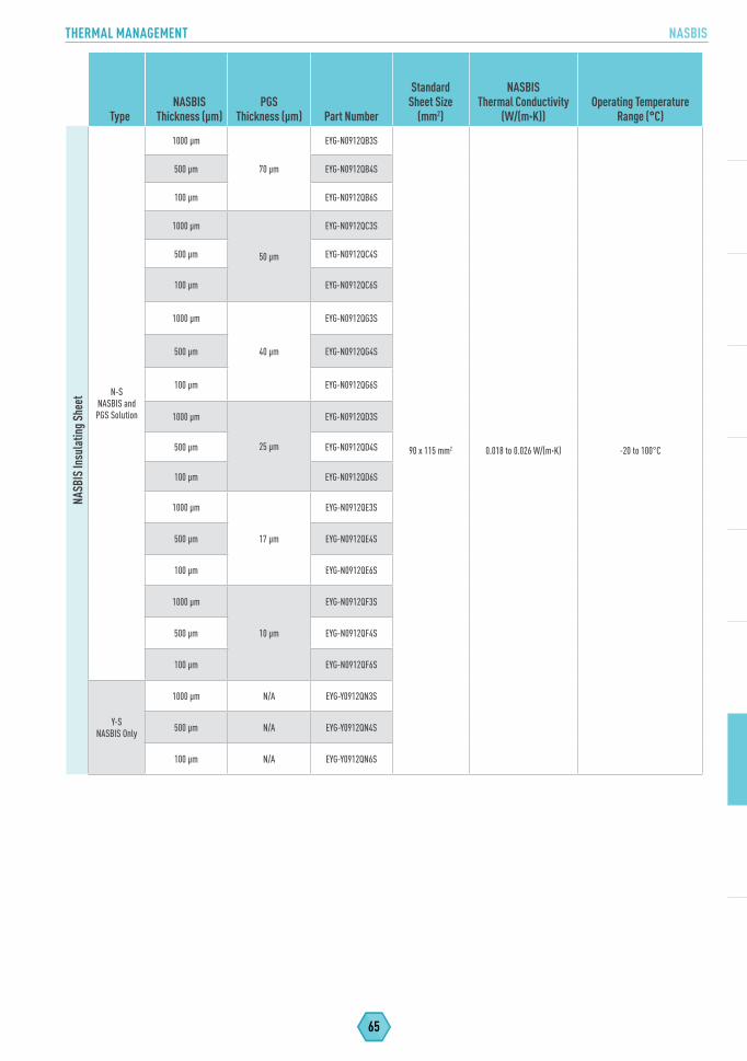
65
THERMAL MANAGEMENT NASBIS
TypeNASBIS
Thickness (µm)PGS
Thickness (µm) Part Number
StandardSheet Size
(mm2)
NASBIS Thermal Conductivity
(W/(m·K))Operating Temperature
Range (°C)
NASB
IS In
sula
ting S
heet
N-SNASBIS and PGS Solution
1000 µm
70 µm
EYG-N0912QB3S
90 x 115 mm2 0.018 to 0.026 W/(m·K) -20 to 100°C
500 µm EYG-N0912QB4S
100 µm EYG-N0912QB6S
1000 µm
50 µm
EYG-N0912QC3S
500 µm EYG-N0912QC4S
100 µm EYG-N0912QC6S
1000 µm
40 µm
EYG-N0912QG3S
500 µm EYG-N0912QG4S
100 µm EYG-N0912QG6S
1000 µm
25 µm
EYG-N0912QD3S
500 µm EYG-N0912QD4S
100 µm EYG-N0912QD6S
1000 µm
17 µm
EYG-N0912QE3S
500 µm EYG-N0912QE4S
100 µm EYG-N0912QE6S
1000 µm
10 µm
EYG-N0912QF3S
500 µm EYG-N0912QF4S
100 µm EYG-N0912QF6S
Y-SNASBIS Only
1000 µm N/A EYG-Y0912QN3S
500 µm N/A EYG-Y0912QN4S
100 µm N/A EYG-Y0912QN6S

NOTES

Explore The Panasonic Blog!Stay Up To Date On The Latest Solutions, How-To’s And
Best Practices For Passive And Active Electronic Components.
Visit The Panasonic Blog: na.industrial.panasonic.com/blog
BLOG

Copyright ® 2017 Panasonic Corporation of North America. | All Rights Reserved. Specifications are subject to change without notice. | Line Card Catalog FY16-095-10000
Panasonic Industrial Devices Sales Company of America Two Riverfront Plaza, 7th Floor, Newark, NJ 07102
800-344-2112 | na.industrial.panasonic.com | [email protected]