industrial belt and drive preventive maintenance - gates industrial belts preventive... · drive...
TRANSCRIPT

Drive the Technology
YOUR DISTRIBUTOR:
Industrial Belt and drivepreventive maintenance
E2/20087

Throughout the years, the Gates Corporation hasplayed a key role in the creation and developmentof high quality belts. Gates’ continuous productdevelopment has resulted in a comprehensiveprogramme of V-belts, synchronous belts,tensioners, pulleys, flexible couplings andcomplete drive systems covering a multitude ofapplications. Typical examples are V-belts suchas Quad-Power II, Super HC® MN, Hi-Power®,PowerBand®, Polyflex® JB™ and Micro-V®.Gates’ synchronous belt range includes the two re-engineered PowerGrip® GT2 and Poly Chain® GT2belt lines, as well as Twin Power® GT2, Long Lengthand SynchroPower® belts. Gates has developed itsEuroGrip® flexible couplings, designed to connecttwo shafts subject to misalignment andaxial movement.
All Gates European Power Transmissionoperations are ISO 9001 and ISO 14001accredited. The international ISO 9001assessment covers design, develop-ment, production, installation andservicing of products and is evidence ofGates’ solid commitment to quality.Gates also achieved the ISO 14001standard by demonstrating thatenvironmental issues and protection aremanaged within a coordinated frameworkof controls and well-defined procedures.
HIGHPERFORMANCE AND
COMPREHENSIVEPRODUCT RANGE
® Registered trademark of the Gates Corporation.

I. Introduction1. Why preventive maintenance? ................................ 22. Components of a good maintenance programme .. 2
II. A safe working environment .............................. 3
III. Preventive “routine” maintenance1. Simple drive inspection ........................................... 42. Frequency of inspection .......................................... 43. When to perform preventive maintenance .............. 4
IV. Drive shutdown and thorough inspection1. Guard inspection ..................................................... 52. Belt inspection ......................................................... 53. Pulley inspection...................................................... 64. Check alignment tolerances .................................... 65. Check other drive components ............................... 66. Check belt tension ................................................... 67. LASER AT-1 laser alignment device ......................... 8
V. Belt and pulley installation1. V-belt installation ..................................................... 92. Pulley installation and alignment ........................... 103. Synchronous belt installation................................. 10
VI. Belt identification1. Industrial belt types ............................................... 112. Cross-sections and nominal
dimensions: V-belts ............................................... 173. Cross-sections and nominal
dimensions: synchronous belts ............................. 19
VII. Belt drive performance evaluation1. Upgrading drive performance ................................ 212. Improving poor drive performance ........................ 21
VIII.Troubleshooting guide1. Problems on V-belt drives ..................................... 222. Problems on synchronous belt drives ................... 233. Problem/cause/solution table ................................ 24
IX. Troubleshooting methods and tools1. Eyes, ears, nose and hands................................... 302. Squirt bottle with soapy water ............................... 303. Ball of string ........................................................... 304. Belt and sheave gauge .......................................... 305. Long straight edge ................................................. 306. Tension meters....................................................... 307. Clamp-on Wattmeter ............................................. 318. Infrared thermometer ............................................. 319. Strobe tachometer ................................................. 31
X. Belt storage1. General guidelines ................................................. 322. Methods of storage ............................................... 323. Effects of storage................................................... 32
XI. Technical data ........................................................ 33
XII. Support ..................................................................... 44
TABLE OF CONTENTS
1
IMPORTANT:Every effort has been made to ensure theaccuracy and comprehensiveness of theinformation included in this manual. However,Gates cannot be held responsible for errors oromissions and for alterations occurred afterrelease for printing, or if Gates products are usedin special or exceptional circumstances withoutprior consultation with and clearance from aGates representative.

2
I. INTRODUCTION
➛Defective drivecomponents
Sources of drive problems
➛Improper beltstorageor handling
1. Why preventive maintenance?When compared to chain drives (with constant lubricationproblems), or gear drives (with mechanical problems andhigh costs), belt drives are the most cost-effective andreliable means of power transmission. This reliability canhowever only be obtained when belts and drives areproperly maintained.
The potential for long service life is built into every Gatesbelt. When coupled to a regular maintenance programme,your belts and drives will run relatively trouble-free for along period of time. Always inspect belts and drives beforethey fail. This will reduce costly downtime and productiondelays.
This manual has been designed as aguide to help you install and maintainGates industrial belts, including standardV-belts, multi-ribbed belts andsynchronous belts. Through properinstallation and maintenance, the servicelife of your belt drives will dramaticallyimprove — reducing downtime andproduction standstills.
2. Components of a goodmaintenance programme
A complete and effective maintenance programme shouldinclude following elements:
• maintaining a safe working environment;• regular belt drive inspections;• proper belt installation procedures;• belt product knowledge;• belt drive performance evaluations;• troubleshooting.
All these aspects will be dealt with in the different sectionsof this manual.
Improper drive maintenance
Environmental factors
Improper belt orpulley installation
Poor drive design

3
II. A SAFE WORKING ENVIRONMENT
It is common sense to establish a safeworking environment in and around yourbelt drives. Besides making maintenanceeasier, the following precautions will ensuresafety for the operator.
1. Trained personnelAlways have trained personnel working on your belt drives.
2. Always turn equipment offTurn off the power to the drive before you start working,even if you are going for a brief inspection. Lock thecontrol box and tag it with a warning sign “Down formaintenance. Do not turn power on.” Keep the key inyour pocket. For added safety, and if possible, removefuses. Inspecting the drive usually involves watching themachine running␣ —␣ but never touch it before it stops.
3. Check position of componentsMake sure all machine components are in a “safe”position. Place fly-wheels, counterweights, gears andclutches in a neutral position to avoid accidentalmovements. Always follow the manufacturer’srecommendations for safe maintenance practices.
4. Wear proper clothingNever wear loose or bulky clothes (e.g. ties, loose sleeves,lab coats) around belt drives. Wear gloves wheninspecting pulleys to avoid being cut by nicks or sharplyworn pulley edges.
5. Maintain safe access to the drivesKeep the areas around the drive free of clutter, debrisand other obstructions. Floors should be clean and freeof oil and debris to ensure good footing and balance ofthe operator whilst working on the machine.
6. Drive guardsAlways keep drives properly guarded. Every belt drivemust be completely guarded while in operation.A makeshift, partial guard is often more dangerous, sinceit gives a false sense of security and encourages unsafeaction. Besides being a safety asset, a good guard makes
No loose or bulky clothing.
A properly guarded belt drive.
Do not clutter area around belt drive.
A properly designed guard has following features:• it completely encloses the drive;
• it is equipped with grills or vents for good ventilation;
• the size of the openings must be adequate, i.e. small enough toprevent "pinch points";
• it is preferably equipped with an automatic shut-off devicewhich deactivates the drive as soon as the guard is removed;
• it has accessible inspection doors or panels;
• it can easily be removed and replaced if damaged;
• where necessary, it should protect the drive from weather,debris and damage.
your maintenance job easier since itprotects the drive from outside damaginginfluences.
7. Test runBefore you put your drive back into normaloperation, have a "test run" to checkwhether everything functions normally.Make any verifications necessary and takecorrective action if needed.

4
III. PREVENTIVE “ROUTINE” MAINTENANCE
Maintenance has two aspects: shorter,regular preventive inspections andthorough inspections with a longer periodof machine shutdown. This section dealswith the first type of routine inspection.
3. When to perform preventivemaintenance
The following guidelines will help you establish apreventive maintenance schedule.
Critical drivesA quick visual and hearing inspection may be neededevery one to two weeks.
Normal drivesWith most drives, a quick visual and hearing inspectioncan be performed once a month.
Complete inspectionA drive shutdown, for a thorough inspection of belts orpulleys and other drive components may be required everythree to six months. See section IV.
1. Simple drive inspectionA good way to begin preventive maintenance is makingperiodic drive inspection a normal part of yourmaintenance rounds.
Look and listenLook and listen for any unusual vibration or sound whileobserving the guarded drive in operation. A well-designedand maintained drive will operate smoothly and quietly.
Guard inspectionInspect the guard for looseness or damage. Keep it freeof debris and grime buildup. Any accumulation of materialon the guard will act as insulation and could cause thedrive to run hotter.Temperature is an important factor of belt performanceand durability. For example, above 60°C an internaltemperature increase of 10°C (50°F) – or approximately20°C (68°F) rise in ambient temperature – may cut V-beltlife in half.
Oil and greaseAlso look for oil or grease dripping from the guard. Thismay indicate over-lubricated bearings. Oil and greaseattack rubber compounds, causing them to swell anddistort. This will lead to early belt failure.
AttachmentsFinally, check motor mounts for proper tightness. Checktakeup slots or rails to see that they are clean and lightlylubricated.
2. Frequency of inspectionThe following factors will influence the frequency of driveinspection:
• drive operating speed;
• drive operating cycle;
• critical nature of equipment;
• temperature extremes in environment;
• environmental factors;
• accessibility of equipment.
Experience with your own equipment will be the best guideto how often you need to inspect the belt drives. Highspeeds, heavy loads, frequent start/stop conditions,extreme temperatures and drives operating on criticalequipment will mean more frequent inspections.

5
IV. DRIVE SHUTDOWN AND THOROUGH INSPECTION
Belt inspection.
Once the drive has been disconnected from power supply and tagged, and the machine components are in safeposition, remove the guard and begin inspection.
1. Guard inspectionCheck guards for wear or possible damage. Look forsigns of wear or rubbing against drive components. Cleanthem to prevent their becoming insulated and closed toventilation. Clean off any grease or oil that may havebeen spilled onto the guard from over-lubricated bearings.
2. Belt inspectionBy observing signs of unusual belt wear or damage, youwill be able to troubleshoot possible drive problems.
Mark a point on the belt, or one of the belts on a multipleV-belt drive. Work your way around the belt(s), checkingfor cracks, frayed spots, cuts or unusual wear patterns.
Check the belt for excessive heat. Belts do warm upwhile operating, but temperatures must not exceed certainlimits. Your hand can tolerate up to about 60°C (140°F);if belts are too hot to touch, troubleshooting may beneeded.
In that case, check the temperature range of the belt youare using.
Belts should be replaced if they show obvious signs ofcracking, fraying, unusual wear or loss of teeth in asynchronous belt.
Belt drives regularly require a thoroughinspection. By following the list below, you canmaintain a drive efficiently, safely and with verylittle effort. When properly maintained andused under normal conditions, a well-designedindustrial belt drive is capable of operating forseveral years.
Preventive maintenance checklist
1. Turn off power to the drive. Lock the control boxand tag it with a warning sign “Down formaintenance. Do not turn power on.”
2. Place all machine components in a safe (neutral)position.
3. Remove and inspect guard. Check for signs ofwear or rubbing against drive components. Cleanguard as needed.
4. Inspect belt for wear or damage. Replace asneeded. Page 9 outlines V-belt replacementprocedure while page 10 covers synchronous beltreplacement procedure.
5. Inspect pulleys for wear or damage. Replace ifworn. Page 10 explains pulley replacementprocedure.
6. Inspect other drive components such as bearings,shafts, motor mounts and takeup rails.
7. Inspect static conductive earthing system (if used)and replace components as needed.
8. Check belt tension and adjust as needed.
9. Recheck pulley alignment.
10. Reinstall belt guard.
11. Turn power on and restart drive. Look and listenfor anything unusual.
These steps are covered in detail further in this manual.
Shut off power and lock controls.
Guard inspection.

6
Parallel misaligment
Angular misaligment
Fleeting angle*
Fleeting angle*
3. Pulley inspectionIf belts have been removed from the drive, check pulleysfor unusual wear or obvious signs of damage. Wear isnot always obvious. Use Gates sheave gauges to checkV-grooves. For synchronous belt drives, check the pulleydiameters over the width of the pulley to ensure they areconsistent and meet our tolerances (see Gates Drivedesign manual E2/20099).
Always check pulleys for proper alignment and mounting.Improperly aligned pulleys result in reduced service life.The main causes of misalignment are:• pulleys are improperly located on the shafts;• motor shafts and driven machine shafts are not parallel;• pulleys are tilted due to improper mounting.
To check alignment, you will need a straight edge or, forlong centre distance drives, heavy string. Line the straightedge or string along a machined face of both pulleys asshown on the picture below. Misalignment will show upas a gap between the face of the pulley and the straightedge or string. When using this method, make sure thedistance between the groove edge and the outer rim ofboth pulleys is identical. Pulleys can also be checked fortilting with a spirit level.
4. Check alignment tolerancesAs a general rule, the deviation on pulley alignmenton V-belt drives should not exceed 1/2° or 5 mm per500 mm of drive centre distance. Alignment forsynchronous, Polyflex®␣ and Micro-V® belts should becontrolled within 1/4° or 2.5 mm per 500 mm of drivecentre distance.
The greater the misalignment, the greater the chance ofbelt instability, increased belt wear and V-belt turnover.
5. Check other drive componentsAlways examine bearings for proper alignment andlubrication. Also check motor mounts for correcttightness. Be sure takeup rails are free of debris,obstructions, dirt or rust.
6. Check belt tensionThe final step is to check belt tension, and, if necessary,retension the belt. Note that retensioning is notrecommended for synchonous belts.
If too little tension is applied, V-belts may slip orsynchronous belts may jump teeth.
The correct tension is the lowest tension at which thebelts will transmit power when the drive is at full load.The general procedure to check belt tension is as follows.
A. Measure at the centre of the span (t) the force requiredto deflect the belt on the drive 2 mm per 100 mm spanlength (synchronous belts) or 1 mm per 100 mm spanlength (V-belts) from its normal position.
B. If the measured force is less than the minimumrecommended deflection force, the belts should betightened.
C. New belts can be tensioned until the deflection forceper belt is as close as possible to the maximumrecommended deflection force.
D. To facilitate tension measuring Gates has developedthe sonic tension meter.
Sonic tension meter
The sonic tension meter measures tension by analysingthe sound waves which the belt produces whenstrummed. A belt vibrates at a particular frequency basedon its tension, mass and span length. The tensiontransforms this frequency in a tension value.
The hand-held tension tester, running on batteries or onthe mains (adapter included), is supplied with two typesof sensors (rigid and flexible), either of which is quicklyattached to meet a specific need.
1. Enter belt unit weight (provided with operatinginstructions), width and span on the keypad. This dataremain in the meter even after shut-off.
2. Hold the small sensor up to the belt span and strumthe belt slightly to make it vibrate.
Use a straight edge to check pulley alignment.
Forms of misalignment
* Refer to "4. Check alignment tolerances".
IV. DRIVE SHUTDOWN AND THOROUGH INSPECTION

7
Belt Small Recommendedcross-section pulley deflection
diameter force*
mm N
min max
Hi-Power®
Z 60 - 67 6 871 - 80 7 985 - 100 8 11
106 - 140 9 12150 - 224 10 14
A 60 - 80 7 1285 - 90 9 1395 - 106 10 15
112 - 180 13 20
B 80 - 106 11 17112 - 118 14 20125 - 140 15 23150 - 170 19 27180 - 1250 22 33
C 150 - 170 21 33180 24 35190 26 38
200 - 212 30 45224 - 265 33 50280 - 400 38 58
D 300 - 335 51 73355 - 400 56 82425 - 560 65 99
Super HC® / Super HC® MN
SPZ / SPZ-MN / 56 - 67 7 103V 71 8 11
75 - 80 9 1385 - 95 10 15
100 - 125 12 17132 - 180 13 19
SPA / SPA-MN 80 - 95 12 16100 - 125 14 21132 - 200 19 28212 - 250 20 30
SPB / SPB-MN / 112 - 150 23 365V 160 - 200 29 44
212 - 280 36 50300 - 400 38 58
SPC / SPC-MN 180 - 236 40 60250 - 355 51 75375 - 530 60 90
8V / 25 J 317 - 431 76 113457 - 610 88 133
8VK 380 - 437 97 145450 - 600 112 166
Quad-Power II
XPZ / 3VX 56 7 1160 - 63 8 1367 - 71 9 1475 - 80 10 1585 - 95 11 16
100 - 125 13 19132 - 180 16 24
XPA 80 - 125 18 27132 - 200 22 31
XPB / 5VX 112 - 118 24 36125 - 140 27 41150 - 170 30 47180 - 200 36 53212 - 280 38 55300 - 400 41 64
XPC 180 - 236 50 75250 - 355 65 95375 - 530 80 110
3. Press the “measure” button. The computer processesthe variations in sound pressure emanating from thebelt span. The belt tension values are displayed onthe panel in Newtons. If desired, the belt spanfrequencies can be displayed directly in Hz.
For more detailed information, e.g. suitability of the tensionmeter for different belt product lines, please contact yourGates representative.
For more details on the use of Gates’ sonic tension meters,please consult Gates’ sonic tension meter manual(E/20106).
* This recommendation is for uncritical drive configurations. For critical drivesindividual design calculations are required.
IV. DRIVE SHUTDOWN AND THOROUGH INSPECTION
Warning: Gates sonic tension meter is not certifiedfor use in explosion risk areas.
Conventional tension testersUnlike the sonic tension meter, Gates’ conventionaltension testers measure deflection force. The Singletension tester measures up to ± 120 N and the Doubletension tester up to ± 300 N. Both testers consist of acalibrated spring with two scales: one to measure thedeflection and another to measure the applied force.
The reading of these scales can be done as follows.
1. Measure the span length (t).
2. The calculated deflection should be positioned withthe lower ring on the distance scale. The upper ringshould be on the zero position of the deflection forcescale.
3. Put the tension tester perpendicular to the span and inthe middle of the span. Exercise enough pressure tothe tension tester to deflect the belt by the amountindicated by the lower ring. A straight edge, laid acrossthe pulleys, can help accuracy of reading.
4. The upper ring will slide up the upper scale andindicates the deflection force. Read at the bottom edgeof the ring. When you use the Double tension testeryou can read the values just underneath the rings andcalculate the sum of both values. This value has to becompared with the calculated min./max. forces (seeSynchronous drive design manual E2/20099).

8
In tensioning a Gates PowerBand® belt, multiply thedeflection force (see table on page 7) by the number ofbelts in the PowerBand®. The tension tester can beapplied as indicated above to deflect the entirePowerBand®, providing a small board or metal plate isplaced on top of the band so that all belts are deflecteduniformly. As a reference for measuring deflection, astraight edge can be laid across the pulleys. If thedeflection force exceeds 30␣ kg (66␣ pounds) — themaximum reading on the tester — use a large spring scaleor consult your Gates representative.
7. LASER AT-1 laser alignment device
t
510
1520
2530
INC
HE
S1
2
510
1520
2530
INC
HE
S1
2
TENSIONTESTER
See printedfolder forcompleteinstructionsfor correctusage
Read just underneath the rings. Before using thetension tester again, slide the rings downwards again.
Deflection force(read up)
Deflection distance(read up)
Rings
Rings
IV. DRIVE SHUTDOWN AND THOROUGH INSPECTION
Double tension tester
t
12
INC
HE
S5
1015
2025
30
TensionTester
Single tension tester
Read just underneath the ring. Before using thetension tester again, slide the ring downwards again.
Deflection forcescale(read up)
Deflection distance scale(read up)
Sliding rubber"O" rings
The LASER AT-1 identifies parallel as well as angularmisalignment between the pulleys and is suitable for pulleydiameters of 60 mm and larger. Mounted in a fewseconds, the laser line projected on the targets allowsyou to quickly ascertain and correct misalignment. It isso light it can be mounted on non-magnetic pulleys withthe double sided adhesive tape and used on bothhorizontally and vertically mounted machines.For more information please see leaflet E2/20121.

9
V. BELT AND PULLEY INSTALLATION
Pulley gauges make wear detection easier.
When the decision has been made toinstall a belt, either as a replacementor on a new drive, follow these recom-mendations for proper installation. Alsoensure correct pulley mounting andalignment.
1. V-belt installation
1. After the power has been turned off, isolated (i.e.locked) and the guard removed, loosen the motormounting bolts. Move the motor until the belt isslack and it can be removed without prising. Neverprise off a belt!
2. Remove old belts. Check them for unusual wear.Excessive wear may indicate problems with drivedesign or maintenance procedures.
3. Select correct replacement belt. Refer to the beltidentification charts on pages 16 and 17 for beltselection information.
4. You can clean belts and pulleys with a rag slightlydampened with a light, non-volatile solvent. Avoidsoaking or brushing the solvent on the belt. Do notsand or scrape the belt with a sharp object toremove grease or debris. Belts must be dry beforeusing on a drive.
5. Inspect pulleys for wear and damage. Gates sheavegauges make it easy to see if grooves are worn. Ifmore than 0.4 mm of wear can be seen, the pulleyshould be replaced. Make sure the pulleys areproperly aligned.
6. Inspect other drive components such as bearingsand shafts for alignment, wear, lubrication,…
7. Install a new belt or belt set. Replace all belts onmultiple belt drives. Do not mix old and new belts.Older belts do not retain tension as well as newbelts. If you mix belts, the load may be carriedonly by the new belts. This can result in prematurefailure. Also, never mix belts from differentmanufacturers. Belts with different origins may havedifferent characteristics that can cause the belts towork against each other, resulting in unusual strainand short service life.
8. Take up centre distance on the drive, rotate the driveby hand for a few revolutions until proper tension isobtained on the tension tester. Some long belts mayappear to hang unevenly when installed. It is normalfor belts within match tolerances to create noticeabledifferences in deflection. This "catenary effect" is a curvemade by a cord of uniform weight suspended betweentwo points. This appearance will change with properrun-in and tensioning.
9. Secure motor mounting bolts to correct torque.
10. Replace guard.
11. Let the belts run in for a while. This process consists ofstarting the drive, letting it run under full load, and thenstopping, checking and retensioning to recommendedvalues. Running the belts under full load allows themto seat themselves in the grooves.If possible, let the drive run for about 24 hours. Evenletting them run overnight, or over a lunch break, is betterthan nothing. This run-in period will reduce the futureneed for retensioning.
12. During start-up, look and listen for unusual noise orvibration. It is a good idea to shut down the machineand check the bearings and motor. If they feel hot, thebelt tension may be too tight. Or the bearing may bemisaligned or improperly lubricated.

10
2. Pulley installation and alignmentIt is extremely important that pulleys be installed andaligned properly. Any pulley must be correctly assembled,and bolts or setscrews tightened to the correct torque.
Most pulleys are attached to the shaft with a taperedbushing which fits a mating tapered bore in the pulley.This type of system consists of a bushing, a pulley andoften a setscrew and key. Bushings come in severaldiameters. This allows a reduction in the parts inventoryrequired in your plant because one bushing can be usedwith a number of different size pulleys.
Taper bushesTo install, insert the bushing into the pulley. Match holes(not threads) and slip the entire unit onto the shaft. Putscrews into the holes that are threaded in the pulley only.Align the pulleys and tighten the screws. As the bushingis wedged inward, it contacts and grips the shaft.
3. Synchronous belt installation
1. After the power has been turned off, isolated (i.e.locked) and the guard removed, loosen the motormounting bolts. Move the motor until the belt is slackand it can be removed without prising. Never priseoff a belt!
2. Remove old belt and check it for unusual wear.Excessive wear may indicate problems with drivedesign or maintenance procedures.
3. Select correct replacement belt. Refer to the beltidentification charts on pages 17 and 20 for beltselection information.
4. Pulleys can be cleaned with a rag slightly dampenedwith a light, non-volatile solvent. Do not sand orscrape the pulley with a sharp object to remove greaseor debris. Pulleys must be dry before using on a drive.
5. Inspect pulleys for unusual or excessive wear. Alsocheck alignment. Correct alignment is more criticalwith synchronous belt drives.
6. Check other drive components such as bearings andshafts for alignment, wear, lubrication,…
7. Install new belt over pulleys. Do not prise or use force.
8. Take up centre distance on the drive until propertension is obtained on the tension tester. Rotate thedrives by hand for a few revolutions and rechecktension.
9. Secure motor mounting bolts to correct torque. Besure all drive components are secure since any changein drive centres during operation will result in poorbelt performance.
10. Although belts will not require further tensioning, werecommend starting up the drive and observingperformance. Look and listen for any unusual noiseor vibration. It is a good idea to shut down themachine and check the bearings and the motor. Ifthey feel hot, the belt tension may be too high. Or thebearings may be misaligned or improperly lubricated.
Taper bush
V. BELT AND PULLEY INSTALLATION
Recommended wrench torque valuesto use in tightening taper bushes
Bushing no. Screw tightening torque (Nm)
1008 5.6
1108 5.6
1210 20.0
1215 20.0
1310 20.0
1610 20.0
1615 20.0
2012 30.0
2517 50.0
2525 50.0
3020 90.0
3030 90.0
3525 115.0
3535 115.0
4030 170.0
4040 170.0
4535 190.0
4545 190.0
5040 270.0
5050 270.0

11
VI. BELT IDENTIFICATIONWhen preventive maintenance inspectionsindicate that belts need replacing, itis important you install the appropriatebelts. Consequently, you should be ableto identify the various types and sizesavailable to achieve quick and correctreplacement.The information on the following pages willhelp you become familiar with the belttypes used in industry.
1. Industrial belt typesGates manufactures many belt types to fit nearly any application you can name. Always make sure you select theappropriate belt for your application. Even though they may look similar, belts have different characteristics. Do notuse light-duty belts on heavy-duty drives, and do not interchange cross-sections. If in doubt carefully measure thetop width, or use the pulley gauges.
The Quad-Power II V-belt features a moulded notch design and is ideal forheavy-duty, high-speed V-belt drives. It replaces traditional V-belts onheavy-duty applications where space and weight savings are critical.
• Moulded notch construction improves flexibility, reduces bending stress andprovides improved performance.
• Tough tensile members resist fatigue and shock loads.• Higher power ratings than classical sections: narrower drives through fewer belts
reduce total drive cost.• Static conductive (ISO 1813).
Available in XPZ, XPA, XPB and XPC cross-sections and in ISO datum lengths from630 mm up to 4750 mm.
Quad-Power II - Gates’ most powerful raw edge, narrow-section V-belt
Super HC® Moulded Notch V-belts put more power where high speeds, high speedratios or small pulley diameters are required, thus offering significant advantagesover classical section V-belts.
• Straight ground sidewalls give uniform wedging action.• Tough tensile members resist fatigue and shock loads.• More power in the same space or same power in 1/3 to 1/2 less space as compared
to classical section V-belts.• Static conductive (ISO 1813).
Available in SPZ, SPA, SPB and SPC cross-sections and in ISO datum lengths from560 mm up to 4750 mm.
Super HC® MN - Raw edge, narrow-section V-belt
V-belts

12
The wrapped classical section Hi-Power® V-belt has a long reputation for reliabilityon agricultural and industrial applications.
• The concave sidewalls straighten out ot the exact shape of the pulley grooves,ensuring full contact with the sides of the pulley.
• The arched top provides superior strength to prevent “dishing” and distortion ofthe tensile section, providing maximum belt life.
• The Flex Weave® oil and heat resistant cover protects the belt core from thetoughest environments.
• The vulcanised Flex Bonded tensile cords provide superior resistance to tensileand flexing forces, fatigue and shock loads.
• Static conductive (ISO 1813).
Hi-Power® is available in Z, A, B, C and D cross-sections and in ISO datum lengthsfrom 470 mm up to 9160 mm. Also available with double-V profile in AA, BB, CCand DD cross-sections and in ISO datum lengths from 965 mm up to 10690 mm.
Hi-Power® - Wrapped, classical section V-belt
VI. BELT IDENTIFICATION
The Super HC® narrow-section V-belt is a popular wrapped construction and suitsan extensive range of industries including mining, quarry and heavy construction.
• Arched top, concave sidewalls and rounded corners provide uniform tensileloading and uniform pulley sidewall contact for excellent belt service life andreduced pulley wear.
• The Flex Weave® oil and heat resistant cover protects the belt core from thetoughest environments.
• The vulcanised Flex Bonded tensile cords provide superior resistance to tensileand flexing forces, fatigue and shock loads.
• Static conductive (ISO 1813).
Super HC® is available in SPZ, SPA, SPB and SPC cross-sections and inISO datum lengths from 560 mm up to 10600 mm.
Super HC® - Wrapped, narrow-section V-belt
Gates’ PowerBand® provides improved performance where single V-belts vibrate,turn over or jump off the pulleys.
• The unique cross cord tie band allows the belt to seat in the pulley groovesindependently and still transmit the load evenly.
• The lateral rigidity prevents belt turnover on shock loaded and pulsating drivesgiving a long service life.
• Static conductive (ISO 1813).
Available in SPB, SPC, 15J, 8V/25J, 3VX and 5VX sections and in lengths from635 mm up to 15240 mm.SPB and SPC PowerBand® belts fit European ISO standard pulleys.
PowerBand® - Multiple V-belt

13
Because of their small cross-sections Polyflex® belts are ideal for compact shortcentre and small diameter drives. Polyflex® single belts as well as Polyflex® JB™multiple V-belts can operate at very high shaft speeds in excess of over10000 rpm.
• Polyurethane compound with high friction coefficient cast as a single unit aftertensile cords are positioned in the mould.
• 60° angle better supports the tensile section providing even load distribution.• Polyflex® JB™ joined belt construction improves stability.
The Polyflex® single belt is available in 3M, 5M, 7M and 11M sections and in effectivelengths from 180 mm up to 2300 mm.The Polyflex® JB™ belt is available in 5M-JB, 7M-JB and 11M-JB sections and ineffective lengths from 280 mm up to 2293 mm.
Polyflex® and Polyflex® JB™ - Polyurethane V-belts
The Multi-Speed V-belt for variable speed drives adjusts itself automatically to thepulley groove providing a wide range of speeds and speed ratios.
• High load-carrying capacity.• Notching increases flexibility and ensures maximum heat dispersion.• Strong transverse rigidity.• Uniform undercord thickness ensures smooth running.
Available in ISO profiles with pitch lengths from 630 mm up to 3150 mm; additionalGates line covers the most popular applications.
Multi-Speed - V-belt for variable speed drives
PoweRated® V-belts have a higher power capacity than conventional light-duty belts.
They are ideal for heavy shock loaded and back idler driven lawn and gardenequipment.
• Strong aramid tensile cords.• Cord reinforcement and low friction wrapping improve clutching operation.
Available in 3L, 4L and 5L sections and in outside circumferences from 406 mm upto 2515 mm.
PoweRated® - Heavy-duty V-belt for clutching applications
VI. BELT IDENTIFICATION
Industrial Micro-V® belts feature truncated V-ribs which increase flexibility, reduceheat build-up and improve crack resistance. This unique design lets the belt performat extra high speeds on smaller diameter pulleys.
• The truncated design stands for: a power capacity increase up to 80% higherthan RMA standards, better tolerance of debris in the pulley groove.
• Polyester tensile member provides superior resistance to fatigue and shock loads.• Highly resistant to oil and heat.
Available in PJ, PL and PM sections and in DIN/ISO effective lengths from 406 mmup to 9931 mm.
Micro-V® - Multi-ribbed belt

14
This is the performance choice for a wide variety of high-speed (above500 rpm) drive applications. PowerGrip® GT2 has twice the load carrying capacityof HTD® belts. PowerGrip® GT2 operates on existing HTD® drives not requiring anyadaptation of the system, but offering a longer service life.
• Tough construction with fibreglass tensile cord, elastomeric teeth and backingand nylon facing.
• Allows design of compact, light-weight and cost-effective drives.• High tooth jump resistance.
Available in 8MGT and 14MGT pitches and in pitch lengths from 384 mm up to6860 mm.
PowerGrip® GT2 - Synchronous belt for a wide variety of high-speed drives
VI. BELT IDENTIFICATION
Synchronous belts
Poly Chain® GT2 is the optimal choice in meeting your needs for low speed (below500 rpm), high torque drive applications.
• Virtually maintenance free, no retensioning needed and therefore an excellentalternative to roller chain.
• Uniquely formulated polyurethane is resistant to chemicals and contaminants.• Tensile cords provide extreme power carrying capacity and flex fatigue life.
Available in 8MGT and 14MGT pitches and in pitch lengths from 640 mm up to4480 mm.Also a Mini Poly Chain® belt with GT tooth is available in 8M pitch and in pitchlengths from 248 mm up to 608 mm.
Poly Chain® GT2 - Polyurethane synchronous belt for low-speed, high-torque drives
Synchronous belts are identified by:1. Belt pitch: distance (mm) between two adjacent tooth centres as measured on the belt’s pitch line.2. Belt pitch length: circumference (mm) as measured along the pitch line.3. Width: top width (mm).4. Tooth profile: see pages 17 and 18 for the easiest way to identify this.
Synchronous belts run on pulleys, which are specified by the following:1. Pitch: distance (mm) between groove centres, measured on the pulley pitch circle. The pitch circle coincides
with the pitch line of the mating belt.2. Number of pulley grooves.3. Width: face width.
NOTE: - The pulley’s pitch diameter is always greater than its outside diameter.- Also note that the belt tooth and pulley grooves should always be of the same profile (shape).
Never interchange pulley and tooth types!

15
The durable and high power PowerGrip® GT belt is very quiet in operation. Ideal forcompact drives in hand tools, kitchen machines, high-precision servomotor drivesand multiaxis applications.
• Ideal for design of compact light weight drives.• Reduced noise levels.• High positioning accuracy.• Improved tooth jump resistance.
Available in 2MR, 3MR and 5MR pitches and in pitch lengths from 74 mm up to2440 mm.
PowerGrip® GT - Synchronous belt for high power transmission on compact drives
Both synchronous belts offer a maintenance free and long lasting alternative tochain and gear drives and are suitable for a wide range of load capacities and speedratios.
• PowerGrip® HTD® belts with curvilinear tooth are designed for speeds up to20000 rpm and capacities up to 1000 kW.
• Classical PowerGrip® belts with trapezoidal tooth profile will provide a powertransmission of up to 150 kW at speeds of up to 10000 rpm.
PowerGrip® HTD® is available in 3M, 5M, 8M, 14M and 20M pitches and in pitchlengths from 105 mm up to 6600 mm.Classical PowerGrip® is available in standard MXL (0.08 inches), XL, L, H, XHand XXH pitches according to ISO 5296 and in pitch lengths from 73 mm up to4572 mm.
PowerGrip® & PowerGrip® HTD® - Classical synchronous belt and synchronous beltfor High Torque Drives
Especially suited for linear movements (automated doors, warehouse conveyorsand elevators), accurate positioning (machine tools, x-y co-ordinate machines) andreversal drives (computers, printers and office equipment).
• High power transmission and high positioning accuracy.• Length stability thanks to high modulus tensile members.• Easy to attach with clamping fixtures.
Long Length - Open-end synchronous belt
Available pitches and lengths:Elastomeric compound: PowerGrip® XL, L, H; HTD® 3M, 5M, 8M & 14M; GT 3MR,5MR & 8MR (30 m lengths);Polyurethane compound:Poly Chain® GT2 8MGT & 14MGT (30 m lengths); SynchroPower® L, H; T5, T10;AT5 and AT10 (50 m lengths).
VI. BELT IDENTIFICATION

16
SynchroPower® provides maximum power transmission with perfect tooth meshingand tight and accurate tolerances. Ideal for office machine drives, paper industry,domestic appliances and many more.
• Load capacities from 0.5 kW up to 30 kW and speed ratios up to 40000 rpm.• Efficiency up to 98%.• Tough polyurethane construction with steel tensile member minimises elongation.
Available pitches and lengths: T2.5, T5 & T10; DL-T5 and DL-T10 double-sidedpitches in single belt lengths from 120 mm to 2250 mm and in slabs of 300 mmwidth ; AT5 and AT10 in single belt lengths from 225 mm up to 1800 mm and inslabs of 200 mm width.
SynchroPower® - Polyurethane belt with metric pitch
All Gates antistatic V-belts are in accordance with the antistatic requirements as stated inEN 13463-5 (pending) - “Non-electrical equipment intended for use in potentially explosiveatmospheres - Part-5: protection by constructural safety” - and can as such be used in theconditions described in the Directive 94/9/EC - ATEX.
The double and directly opposite teeth of Twin Power® synchronous belts ensurehigh loading capacity on contrarotating drives as well as smooth running andhigh flexibility. The new Twin Power® GT2 belt with unique GT2 tooth profileoutperforms all previous Twin Power® constructions having twice the power ratingof Twin Power® HTD® belts.
• Transmission of 100% of its maximum rated load from either side of the belt.• Alternatively, it can transmit a load on both sides provided the sum of the loads
does not exceed the maximum capacity.
Available pitches and lengths: PowerGrip® GT2 8MGT and 14MGT and pitch lengthsfrom 480 mm up to 6860 mm; PowerGrip® XL, L and H and pitch lengths from381 mm up to 4318 mm.
Twin Power® - Double-sided synchronous belt
VI. BELT IDENTIFICATION
EuroGrip® flexible couplings feature OGEE lines allowing the coupling to act as atorque/life indicator for the drive, and a high damping capacity, which makes themespecially suitable for direct drive applications in pumps and compressors.
• Sleeves of high-performance elastomeric compound.• End pieces of high-grade aluminium reduce weight and inertia. Available either
with finished bore and keyway or to suit a taper bush.• Zero backlash results in high positioning accuracy.• High vibration damping.• Low noise levels and quiet in operation.• High tolerance of combinations of radial and angular misalignment.• Conforms to DIN 740 part 2.
Available in sizes 19, 28, 42, 48 and 60 and bored to suit taper bush or a plainbore and keyway.
EuroGrip® coupling
Flexible couplings

17
VI. BELT IDENTIFICATION
2. Cross-sections and nominal dimensions: V-beltsQuad-Power IIRaw edge, moulded notch, narrow section V-belt
WIDTH HEIGHT
mm mm
XPZ 10 8
XPA 13 10
XPB 16 13
XPC 22 18
Hi-Power®
Wrapped, classical section V-beltWIDTH HEIGHT
mm mm
Z 10 6
A 13 8
B 17 10
C 22 12
D 32 19
Super HC®
Wrapped, narrow section V-belt
WIDTH HEIGHT`
mm mm
SPZ 10 8
SPA 13 10
SPB 16 13
SPC 22 18
Super HC® MN
Raw edge, moulded notch, narrow section V-belt
WIDTH HEIGHT
mm mm
SPZ 10 8
SPA 13 10
SPB 16 13
SPC 22 18
PowerBand®
Multiple V-belt
WIDTH HEIGHT SPACING
mm mm mm
3VX 10 8 10.30
5VX 16 13 17.50
SPB 16 13 19.00
SPC 22 18 25.50
9J 10 8 10.30
15J 16 13 17.50

18
VI. BELT IDENTIFICATION
PoweRated®
Special capacity V-belt HEIGHT SPACING
inch inch
3L 3/8 7/32
4L 1/2 5/16
5L 21/32 3/8
Polyflex® JB™Polyurethane multiple V-belt
WIDTH HEIGHT SPACING
mm mm mm
5M-JB 5 3.3 5.3
7M-JB 7 5.3 8.5
11M-JB 11 7.1 13.2
Micro-V®
Multi-ribbed belt HEIGHT SPACING
mm mm
PJ 3.6 2.34
PL 6.4 4.70
PM 12.5 9.40
Polyflex®
Polyurethane V-belt WIDTH HEIGHT
mm mm
3M 3 2.3
5M 5 3.3
7M 7 5.3
11M 11 7.1

19
3. Cross-sections and nominal dimensions: synchronous belts
PowerGrip® GTSynchronous belt for high power transmission oncompact drives
PITCH TOTAL TOOTH
HEIGHT HEIGHT
mm mm mm
2MR 2 1.52 0.71
3MR 3 2.41 1.12
5MR 5 3.81 1.92
PowerGrip® HTD®
Synchronous belt for High Torque DrivesPITCH TOTAL TOOTH
HEIGHT HEIGHT
mm mm mm
3M 3 2.4 1.2
5M 5 3.8 2.1
8M 8 6.0 3.4
14M 14 10.0 6.0
20M 20 13.2 8.4
PowerGrip® GT2Synchronous belt for a wide variety of high-speeddrives
PITCH TOTAL TOOTH
HEIGHT HEIGHT
mm mm mm
8MGT 8 5.6 3.4
14MGT 14 10.0 6.0
VI. BELT IDENTIFICATION
Poly Chain® GT2Polyurethane synchronous belt for low-speed,high-torque drives
PITCH TOTAL TOOTH
HEIGHT HEIGHT
mm mm mm
8MGT 8 5.9 3.4
14MGT 14 10.2 6.0
PowerGrip®
Classical synchronous beltPITCH TOTAL TOOTH
HEIGHT HEIGHT
inch mm mm
MXL 0.08" 1.14 0.51
XL 1/5 2.3 1.27
L 3/8 3.5 1.91
H 1/2 4.0 2.29
XH 7/8 11.4 6.35
XXH 1 1/4 15.2 9.53

20
VI. BELT IDENTIFICATION
Long LengthOpen-end synchronous belt
PITCH TOTAL TOOTH
HEIGHT HEIGHT
mm mm
PowerGrip® GT mm
3MR 3 2.41 1.12
5MR 5 3.81 1.92
8MR 8 6.00 3.34
PowerGrip® HTD® mm
3M 3 2.40 1.10
5M 5 3.81 2.06
8M 8 6.00 3.40
14M 14 10.00 6.10
PowerGrip® inch
XL 1/5 2.30 1.27
L 3/8 3.60 1.91
H 1/2 4.30 2.29
SynchroPower® mm
T5 5 2.20 1.20
T10 10 4.50 2.50
AT5 5 2.70 1.20
AT10 10 5.00 2.50
inch
L 3/8 3.60 1.91
H 1/2 4.30 2.29
Poly Chain® GT2 mm
8MGT 8 5.90 3.40
14MGT 14 10.20 6.00
PITCH TOTAL TOOTH
HEIGHT HEIGHT
mm mm mm
T2,5 2.5 1.30 0.70
T5 5.0 2.20 1.20
DL-T5 5.0 3.40 1.20
T10 10.0 4.50 2.50
DL-T10 10.0 7.00 2.50
AT5 5.0 2.7 1.2
AT10 10.0 5.0 2.5
PITCH TOTAL TOOTH
HEIGHT HEIGHT
mm mm
mm
8MGT 8 8.27 3.400
14MGT 14 14.83 5.820
inch
XL 1/5 3.05 1.27
L 3/8 4.58 1.91
H 1/2 5.95 2.29
SynchroPower®
Polyurethane synchronous belt, metric pitch
Twin Power®
Double-sided synchronous belt
EuroGrip®
Flexible couplings
For detailed sleeve and end-piece dimensions ofEuroGrip® couplings, please see catalogue E2/20103.

21
VII. BELT DRIVE PERFORMANCE EVALUATION
To provide proper maintenance, you needto understand the nature of the belt drivesin your plant.
You know the expected belt service life of each drive. And you are aware of the capabilities and limitations of thisequipment. Sometimes, however, it is necessary to give some thought to belt service life, especially on theseoccasions:
• When belt service life is meeting expectations, but you would like to reduce existing maintenance and downtime;• When belt service life is below the expected performance level and the situation must be improved.
1. Upgrading drive performanceA belt drive can sometimes be upgraded to improveperformance. The first step is to see if simple improve-ments can be made at minimal costs. This involveschecking the drive design for adequate capacity.
Here are examples of minor changes thatcould improve performance:
• increase pulley diameters;
• increase the number of belts, or use wider belt;
• add vibration dampening to the system;
• improve guard ventilation to reduce operatingtemperature;
• make sure pulley and back idler diameters are abovethe minimum recommended diameters;
• use premium belts rather than general purpose types;
• replace worn pulleys;
• keep pulleys properly aligned;
• place idler on span with lowest tension and as close todriveR pulley as possible;
• re-tension newly installed friction belts after a 4-24 hourrun-in period;
• review proper belt installation and maintenanceprocedures.
If further improvement is needed, the next step is toupgrade the drive to a higher performance belt system.
Gates is the recognised industry leader in productinnovation and belt drive technology. New products andapplications are continually made available to Gatescustomers.
You may have a problem or excessive maintenance costswith a non-belt drive, such as a gear or chain drive. Yourlocal Gates representative can offer you excellent adviceas to whether or not a belt drive could solve the problemand reduce your maintenance costs.
Your local Gates distributor or representative can helpyou upgrade your existing drives and reduce yourmaintenance and downtime costs.
2. Improving poor drive performanceIf your belt drive is correctly designed, installed andmaintained, it will need very little attention. Occasionally,however, a drive may be accidentally damaged or knockedout of adjustment.
Changing operating requirements or environmentalconditions can also create problems. The followingtroubleshooting guide is designed to help you identify andcorrect poor drive performance problems.

22
VIII. TROUBLESHOOTING GUIDE
When troubleshooting a drive problem,your goal is to identify the cause(s) andthen to take appropriate corrective action.The information in this section will help youput your drive back in operation.
Start by a description of the problem.
• What is wrong?• When did it happen?• How often does it happen?• What is the drive application?• Have the machine operations or output changed?• What kind(s) of belts are you using?• What are your expectations for belt performance in
this application?
Using the lists on these pages, check the problems youobserve. Then move to the problem/cause/solution tableon pages 24-29.
1. Problems on V-belt drives
Premature belt failure• Broken belt(s)• Belt(s) fail(s) to carry load (slip), without visible reason• Edge cord failure• Belt delamination or undercord separation
Severe or abnormal belt wear• Wear on belt top surface• Wear on belt top corners• Wear on belt sidewalls• Wear on belt bottom corners• Wear on belt bottom surface• Undercord cracking• Burn or hardening on bottom or sidewall• Extensive hardening of belt exterior• Belt surface flaking, sticky or swollen
V-belts turn over or come off drive• Single belt• One or more belts in a set• Joined or banded belts
Belt stretches beyond available takeup• Single belt• Multiple belts stretch unequally• All belts stretch equally
Belt noise• Squeal or “chirp”• Slapping noise• Rubbing sound• Grinding sound• Unusually loud drive
Unusual vibration• Belts flapping• Excessive vibration in drive system
Banded (joined) belt problems• Tie-band separation• Top of tie-band frayed, worn or damaged• PowerBand
® comes off drive
• One or more strands run outside of pulley
Problems with pulleys• Broken or damaged pulley• Severe, rapid groove wear
Problems with drive components• Bent or broken shafts• Damaged guard
Hot bearings• Belt overtensioned• Pulleys too small• Poor bearing condition• Pulleys too far out on shaft• Belt slippage
Performance problems• Incorrect driveN speeds

23
2. Problems on synchronous belt drives
Belt problems• Unusual noise• Tension loss• Excessive belt edge wear• Tensile break• Belt cracking• Premature tooth wear• Tooth shear
Pulley problems• Flange failure• Unusual pulley wear
Performance problems• Belt tracking problems• Excessive temperature: bearings,
housings, shafts, etc.• Shafts out of synchronisation• Vibration• Incorrect driveN speeds
What to do when all else failsWe have made every effort to cover all of the common drive problems that you may encounter. However, if theproblem still exists after all your troubleshooting efforts have been exhausted, contact your Gates distributor. Ifhe cannot solve the problem for you, he will put you in touch with a Gates representative. Expert help is alwaysavailable to you.
VIII. TROUBLESHOOTING GUIDE

24
3. Problem/cause/solution tableSOLUTIONPROBABLE CAUSESYMPTOMS
SE
VE
RE
OR
AB
NO
RM
AL
BE
LT W
EA
RP
RE
MA
TU
RE
BE
LT F
AIL
UR
E
Broken belt(s) 1. Underdesigned drive 1. Redesign using Gates Drivedesign manual (E2/20070).
2. Belt rolled or prised onto pulley 2. Use drive takeup when installing.3. Object falling into drive 3. Provide adequate guard or drive
protection.4. Severe shock load 4. Redesign to accomodate shock load.
Belt fails to carry load (slip); 1. Underdesigned drive 1. Redesign using Gates Driveno visible reason design manual (E2/20070).
2. Damaged tensile member 2. Follow correct installation procedure.3. Worn pulley grooves 3. Check for groove wear, replace as
needed.4. Centre distance movement 4. Check drive for centre distance
movement during operation.
Edge cord failure 1. Pulley misalignment 1. Check and correct alignment.2. Damaged tensile member 2. Follow installation procedure.
Belt delamination or undercord 1. Pulleys too small 1. Check drive design, replace withseparation larger pulleys.
2. Back idler too small 2. Increase back idler to acceptablediameter.
Wear on belt top surface 1. Rubbing against guard 1. Replace or repair guard.2. Idler malfunction 2. Replace idler.
Wear on belt top corner 1. Belt-to-pulley fit incorrect 1. Use correct belt-to-pulley(belt too small for groove) combination.
Wear on belt sidewalls 1. Belt slip 1. Retension until slipping stops.2. Misalignment 2. Realign pulleys.3. Worn pulleys 3. Replace pulleys.4. Incorrect belt 4. Replace with correct belt size.
Wear on belt bottom corners 1. Belt-to-pulley fit incorrect 1. Use correct belt-to-pulleycombination.
2. Worn pulleys 2. Replace pulleys.
Wear on belt bottom surface 1. Belt bottoming on pulley groove 1. Use correct belt/pulley match.2. Worn pulleys 2. Replace pulleys.3. Debris in pulleys 3. Clean pulleys.
Undercord cracking 1. Pulley diameter too small 1. Use larger diameter pulleys.2. Belt slip 2. Retension.3. Back idler too small 3. Use larger diameter back idler.4. Improper storage 4. Do not coil belt too tightly, kink or
bend. Avoid heat and direct sunlight.
VIII. TROUBLESHOOTING GUIDE

25
SOLUTIONPROBABLE CAUSESYMPTOMS
V-B
ELT
S T
UR
N O
VE
R O
RC
OM
E O
FF D
RIV
EB
ELT
ST
RE
TC
HE
S B
EY
ON
DA
VAIL
AB
LE T
AK
EU
PS
EV
ER
E O
R A
BN
OR
MA
L B
ELT
WE
AR
BE
LT N
OIS
E
Burn or hardening on bottom or 1. Belt slip 1. Retension until slipping stops.sidewall 2. Worn pulleys 2. Replace pulleys.
3. Underdesigned drive 3. Redesign using Gates Drivedesign manual (E2/20070).
4. Shaft movement 4. Check for centre distance changes.
Extensive hardening of belt exterior 1. Hot drive environment 1. Improve ventilation to drive.
Belt surface flaking, sticky or swollen 1. Oil or chemical contamination 1. Do not use belt dressing. Eliminatesources of oil, grease or chemicalcontamination.
Involves single or multiple belts 1. Shock loading or vibration 1. Check drive design. Use GatesPowerBand® belts.
2. Foreign material in grooves 2. Shield grooves and drive.3. Misaligned pulleys 3. Realign pulleys.4. Worn pulley grooves 4. Replace pulleys.5. Damaged tensile member 5. Use correct installation and belt
storage procedure.6. Incorrectly placed flat idler pulley 6. Carefully place flat idler on slack
side of drive as close as possible todriveR pulleys.
7. Mismatched belt set 7. Replace with new set of matchedbelts. Do not mix old and new belts.
8. Poor drive design 8. Check for centre distance stabilityand vibration dampening.
Multiple belts stretch unequally 1. Misaligned drive 1. Realign and retension drive.2. Debris in pulleys 2. Clean pulleys.3. Broken tensile member or cord 3. Replace all belts, install properly.
damaged4. Mismatched belt set 4. Install matched belt set.
Single belt, or where all belts 1. Insufficient takeup allowance 1. Check takeup. Use allowancestretch evenly specified in Gates Drive
design manual (E2/20070).2. Grossly overloaded or underdesigned 2. Redesign drive.
drive3. Broken tensile members 3. Replace belt, install properly.
Squeal or “chirp” 1. Belt slip 1. Retension.2. Contamination 2. Clean belts and pulleys.
Slapping noise 1. Loose belts 1. Retension.2. Mismatched set 2. Install matched belt set.3. Misalignment 3. Realign pulleys so all belts share load
equally.
Rubbing sound 1. Guard interference 1. Repair, replace or redesign guard.
VIII. TROUBLESHOOTING GUIDE

26
SOLUTIONPROBABLE CAUSESYMPTOMS
BE
LT N
OIS
EB
AN
DE
D (J
OIN
ED
) BE
LT P
RO
BLE
MS
UN
US
UA
L V
IBR
AT
ION
Grinding sound 1. Damaged bearings 1. Replace, align and lubricate.
Unusually loud drive 1. Incorrect belt 1. Use correct belt size. Use correctbelt tooth profile for pulleys onsynchronous drive.
2. Worn pulleys 2. Replace pulleys.3. Debris in pulleys 3. Clean pulleys, improve shielding,
remove rust, paint or dirt fromgrooves.
Belts flapping 1. Belts undertensioned 1. Retension.2. Mismatched belts 2. Install new matched set.3. Pulley misalignment 3. Align pulleys.
Excessive vibration in drive system 1. Incorrect belt 1. Use correct belt cross-section inpulley.
2. Poor machine or equipment design 2. Check structure and brackets foradequate strength.
3. Pulley out of round 3. Replace pulley.4. Loose drive components 4. Check machine components and
guards, motor mounts, motor pads,bushings, brackets and framework forstability, adequate design strength,proper maintenance and properinstallation.
Tie-band separation 1. Worn pulleys 1. Replace pulleys.2. Improper groove spacing 2. Use standard groove pulleys.
Top of tie-band frayed, worn 1. Interference with guard 1. Check guard.or damaged 2. Back idler malfunction or damaged 2. Repair or replace back idler.
PowerBand® comes off drive 1. Debris in pulleys 1. Clean grooves. Use single belts toprevent debris from being trapped ingrooves.
One or more ribs run outside of pulley 1. Misalignment 1. Realign drive.2. Undertensioned 2. Retension.
VIII. TROUBLESHOOTING GUIDE

27
SOLUTIONPROBABLE CAUSESYMPTOMSP
RO
BLE
MS
WIT
H P
ULL
EY
SH
OT
BE
AR
ING
SP
RO
BLE
MS
WIT
H O
TH
ER
DR
IVE
CO
MP
ON
EN
TS
Bent or broken shaft 1. Extreme belt overtension 1. Retension.2. Overdesigned drive* 2. Check drive design, may need to use
smaller or fewer belts.3. Accidental damage 3. Redesign drive guard.4. Machine design error 4. Check machine design.
Damaged guard 1. Accidental damage or poor 1. Repair, redesign for durability.guard design
Broken or damaged pulley 1. Incorrect pulley installation 1. Do not tighten bushing bolts beyondrecommended torque values.
2. Foreign objects falling into drive 2. Use adequate drive guard.3. Excessive rim speeds 3. Keep pulley rim speeds below
maximum recommended values.4. Incorrect belt installation 4. Do not prise belts onto pulleys.
Severe, rapid groove wear 1. Excessive belt tension 1. Retension, check drive design.2. Sand, debris or contamination 2. Clean and shield drive as well as
possible.
Belt overtensioned 1. Worn grooves —␣ belts bottoming and 1. Replace pulleys, tension drivewill not transmit power until properly.overtensioned*
2. Improper tension 2. Retension.
Pulleys too small 1. Motor manufacturer’s pulley diameter 1. Redesign using Gates Driverecommendation not followed design manual (E2/20070).
Poor bearing condition 1. Bearing underdesigned 1. Check bearing design.2. Bearing not properly maintained 2. Align and lubricate bearing.
Pulleys too far out on shaft 1. Error or obstruction problem 1. Place pulleys as close as possible tobearings. Remove obstructions.
Belt slippage 1. Drive undertensioned 1. Retension.
* Using too many belts, or belts that are too large, can severely stress motor or driveN shafts. This canhappen when load requirements are reduced on a drive, but the belts are not redesigned accordingly.This can also happen when a drive is greatly overdesigned. Forces created from belt tensioning aretoo great for the shafts.
VIII. TROUBLESHOOTING GUIDE

28
SOLUTIONPROBABLE CAUSESYMPTOMS
PR
OB
LEM
S W
ITH
SY
NC
HR
ON
OU
S B
ELT
SPE
RFO
RM
AN
CE
PR
OB
LEM
S
Incorrect driveN speeds 1. Design error 1. Use correct driveR/driveN pulley sizefor desired speed ratio.
2. Belt slip 2. Retension drive.
Unusual noise 1. Misaligned drive 1. Correct alignment.2. Too low or high tension 2. Adjust to recommended value.3. Back idler 3. Use inside idler.4. Worn pulley 4. Replace pulley.5. Bent guide flange 5. Replace guide flange.6. Belt speed too high 6. Redesign drive.7. Incorrect belt profile for pulley 7. Use proper belt/pulley
(i.e. HTD®, GT, etc) combination.8. Subminimal diameter 8. Redesign drive using larger
diameters.9. Excess load 9. Redesign drive for increased
capacity.
Tension loss 1. Weak support structure 1. Reinforce structure.2. Excessive pulley wear 2. Use other pulley material.3. Fixed (non-adjustable) centres 3. Use inside idler for belt adjustment.4. Excessive debris 4. Remove debris, check guard.5. Excessive load 5. Redesign drive for increased
capacity.6. Subminimal diameter 6. Redesign drive using larger
diameters.7. Belt, pulley or shafts running too hot 7. Check for conductive heat transfer
from prime mover.8. Unusual belt degradation 8. Reduce ambient drive temperature
to +85°C (185°F) maximum.
Excessive belt edge wear 1. Damage due to handling 1. Follow proper handling instructions.2. Flange damage 2. Repair flange or replace pulley.3. Belt too wide 3. Use proper width pulley.4. Belt tension too low 4. Adjust tension to recommended
value.5. Rough flange surface finish 5. Replace or repair flange (to eliminate
abrasive surface).6. Improper tracking 6. Correct alignment.7. Belt hitting drive guard or bracketry 7. Remove obstruction or use inside
idler.
Tensile break 1. Excessive shock load 1. Redesign drive for increasedcapacity.
2. Subminimal diameter 2. Redesign drive using largerdiameters.
3. Improper belt handling and storage 3. Follow proper handling and storageprior to installation procedures.
4. Debris or foreign object in drive 4. Remove object and check guard.5. Extreme pulley run-out 5. Replace pulley.
Belt cracking 1. Subminimal diameter 1. Redesign drive using larger diameter.2. Back idler 2. Use inside idler or increase diameter
of back idler.3. Extreme low temperature at start-up 3. Pre-heat drive environment.4. Extended exposure to harsh chemicals 4. Protect drive.5. Cocked bushing/pulley assembly 5. Install bushing as per instructions.
VIII. TROUBLESHOOTING GUIDE

29
SOLUTIONPROBABLE CAUSESYMPTOMS
Premature tooth wear 1. Too low or too high belt tension 1. Adjust to recommended value.2. Belt running partly off unflanged 2. Correct alignment.
pulley3. Misaligned drive 3. Correct alignment.4. Incorrect belt profile for pulley 4. Use proper belt/pulley
(i.e. HTD®, GT, etc) combination.5. Worn pulley 5. Replace pulley.6. Rough pulley teeth 6. Replace pulley.7. Damaged pulley 7. Replace pulley.8. Pulley not to dimensional specification 8. Replace pulley.9. Belt hitting drive bracketry or other 9. Remove obstruction or use idler.
structure10. Excessive load 10. Redesign drive for increased
capacity.11. Insufficient hardness of pulley 11. Use a more wear-resistant pulley.
material12. Excessive debris 12. Remove debris, check guard.13. Cocked bushing/pulley assembly 13. Install bushings as per instructions.
Tooth shear 1. Excessive shock loads 1. Redesign drive for increasedcapacity.
2. Less than 6 teeth in mesh 2. Redesign drive.3. Extreme pulley run-out 3. Replace pulley.4. Worn pulley 4. Replace pulley.5. Back idler 5. Use inside idler.6. Incorrect belt profile for pulley 6. Use proper belt/pulley combination
(i.e. HTD®, GT, etc)7. Misaligned drive 7. Correct alignment.8. Belt undertensioned 8. Adjust tension to recommended value.
Flange failure 1. Belt forcing flange off 1. Correct alignment or properly secureflange to pulley.
Unusual pulley wear 1. Pulley has too little wear resistance 1. Use alternative pulley material.(e.g. plastic, soft metals, aluminium)
2. Misaligned drive 2. Correct alignment.3. Excessive debris 3. Remove debris, check guard.4. Excessive load 4. Redesign drive for increased capacity.5. Too low or too high belt tension 5. Adjust tension to recommended value.6. Incorrect belt profile for pulley 6. Use proper belt/pulley combination.
(i.e. HTD®, GT, etc)
Belt tracking problems 1. Belt running partly off unflanged 1. Correct alignment.pulley
2. Centres exceed 8 times small pulley 2. Correct parallel alignment to set beltdiameter and both pulleys are flanged to track on both pulleys.
3. Excessive belt edge wear 3. Correct alignment.
Excessive temperature: belt, bearings, 1. Misaligned drive 1. Correct alignment.housings or shafts, etc. 2. Too low or too high belt tension 2. Adjust tension to recommended value.
3. Incorrect belt profile for pulley 3. Use proper belt/pulley combination.(i.e. HTD®, GT, etc)
Shafts out of synchronisation 1. Design error 1. Use correct pulley sizes.2. Incorrect belt 2. Use correct belt with correct tooth
profile for grooves.
Vibration 1. Incorrect belt profile for pulley 1. Use proper belt/pulleycombination (i.e. HTD®, GT, etc)
2. Too low or too high belt tension 2. Adjust tension to recommended value.3. Bushing or key loose 3. Check and reinstall as per
instructions.
Incorrect driveN speeds 1. Design error 1. Redesign drive.
PE
RFO
RM
AN
CE
PR
OB
LEM
S W
ITH
SY
NC
HR
ON
OU
S B
ELT
SP
ULL
EY
PR
OB
LEM
SP
RO
BLE
MS
WIT
H S
YN
CH
RO
NO
US
BE
LTS
VIII. TROUBLESHOOTING GUIDE

30
IX. TROUBLESHOOTING METHODS AND TOOLS
To determine the cause of a drive problem,you can rely on a range of tools from thesurprisingly simple to the technical - someof which are available from Gates. Anoverview of the possibilities.
3. Ball of stringVariation in drive centre distance, often caused by a weaksupporting structure, can cause problems from vibrationto short belt life. To determine if centre distance variationexists, turn off the drive and tightly tie a piece of stringfrom the driveR to the driveN shaft.Start up the drive and note if the string stretches almostto the point of breaking, or goes slack. If either is thecase, the problem could be centre distance variation. Itis particularly important you observe the string at themoment of start-up, when the loads are highest.String can also be used to check pulley alignment.
1. Eyes, ears, nose and handsObserving the drive while in operation or at rest mayindicate problem areas. Can you see anything unusualabout the way the belt travels around the drive? Do yousmell warm rubber? Is the drive frame flexing under load?Do you hear chirping, squealing or grinding noises? Isthere an accumulation of fabric dust under the drive whichmay interfere with the belts?
Once the drive is shut down, you can use your hands.Your hand can tolerate up to about 60°C (140°F), themaximum temperature at which a properly maintained beltshould operate. If you cannot touch the belt afteroperation, this could indicate a problem which causesheat buildup.
Feel the pulley grooves. They should be smooth, free ofnicks and debris. Inspect the belt for unusal wearpatterns, signs of burning or cracking.
4. Belt and sheave gaugeIf you suspect a belt-to-pulley groove mismatch in aV-belt drive, belt and sheave gauges can be used to checkdimensions. These are also handy for identifying a beltcross-section for replacements, and for checking pulleygrooves for wear. Available from your belt supplier.
5. Long straight edgeWhile V-belts can be somewhat forgiving of misalignment,this condition can still affect V-belt performance. Evenslight misalignment can cause major problems on asynchronous drive.Use a long straight edge to quickly check drive alignment.Simply lay the straight edge across the pulley faces andnote the points of contact (or lack of contact). Rememberto check whether pulleys are identical before starting.
2. Squirt bottle with soapy waterWhen a belt drive is excessively noisy, the belt is oftenincorrectly blamed. With V- or Micro-V® belt drives, spraythe belt with soapy water while the drive is running. If thenoise goes away or decreases, the belt is part of theproblem. If you still hear the same noise, the problem islikely to be due to other drive components.
6. Tension metersImproper belt tension, either too high or too low, can causebelt drive problems. Although the “experienced thumb”will suit ordinary V-belt drives, Gates recommends theuse of the tension gauge for critical drives. Several tensionmeter types are available. The pencil type suits mostsituations. To facilitate tension measuring, Gates hasdeveloped two tension testers. The “Single tension tester”measures deflection force of up to ±12␣ kg and the “Doubletension tester” measures deflection force of up to ±30␣ kg.
Gates also supplies a sonic tension meter working withsound waves. The prime advantage of this device iscomplete reliability and hence repeatability ofmeasurement. Consult your Gates representative forsuitability of the tension meter for different belt productlines.Also consult pages 6 to 8 for more information.

31
IX. TROUBLESHOOTING METHODS AND TOOLS
7. Clamp-on WattmeterIf belts are failing prematurely, it is possible the driveNload was underestimated when the drive wasdesigned. Use the Wattmeter to check the actualload being delivered by an electric motor. The clamp-on style allows you to do this safely, without baringwires or worrying about electrical connections.This tool can also be used to troubleshoot vibrationproblems if they are caused by electrical sourcessuch as arcing switches, power surges or electricalconnections.
8. Infrared thermometerWhile your hands can be the first check for belttemperature problems, the infrared thermometerallows you to measure belt temperatures moreaccurately. The device collects the infrared energyradiated by the belt and transforms it into atemperature value.
9. Strobe tachometerYou cannot always see what is happening to a drivewhile it is in operation. This instrument allows youto stop the action to get a better idea of the dynamicforces affecting the drive. The strobe tachometer isbest used after initial diagnosis of the problembecause it helps pinpoint the cause. It will help youidentify such things as single or dual mode belt spanvibration and frame flexure.

32
X. BELT STORAGE
1. General guidelinesStore your belts in a cool and dry environment with nodirect sunlight. When stacked on shelves, the stacksshould be small enough to prevent distortion of the bottombelts. When stored in containers, the container size shouldbe sufficiently limited for the same reason.
Caution:• Do not store belts on floors unless a suitable container
is provided. They may be exposed to waterleaks ormoisture or be damaged due to traffic.
• Do not store belts near windows (sunlight / moisture).• Do not store belts near radiators or heaters or in the air
flow from heating devices.• Do not store belts in the vicinity of transformers, electric
motors, or other electric devices that may generateozone.
• Avoid areas where evaporating solvents or otherchemicals are present in the atmosphere.
• Do not store belts in a configuration that would resultin bend diameters less than the minimumrecommended pulley diameter for normal bends andless than 1.2 times the minimum recommendeddiameters for reverse bends (consult section XI forminimum recommended diameters).
2. Methods of storage2.1 V-beltsV-belts are often stored on pegs. Very long belts shouldbe stored on sufficiently large pins (of not less than theminimum bend diameter), or crescent-shaped “saddles”,to prevent their weight from causing distortion. LongV-belts may be coiled in loops for easy distortion-freestorage.
2.2 Joined V-belts and multi-ribbed beltsLike V-belts, these belts may be stored on pins or saddleswith precaution to avoid distortion. However, belts of thistype up to approx. 3000␣ mm are normally shipped in a“nested” configuration, and it is necessary that especiallyjoined V-belts be stored in a naturally relaxed form, andonly nested or rolled up for transportation.
2.3 Synchronous beltsFor synchronous belts, nests are formed by laying a belton its side on a flat surface and placing as many beltsinside the first belt as possible without undue force. Whentight, the nests can be stacked without damage.Poly␣ Chain®␣ GT2 belts are shipped in individual cartonsand are best left in these until ready to fit to the drive.
Under favourable storage conditions,good quality belts retain their initialserviceability and dimensions. Conversely,unfavourable conditions can adverselyaffect performance and cause dimensionalchanges.
Belts over approx. 3000␣ mm may be “rolled up” and tiedfor shipment. These rolls may be stacked for easy storage.Avoid small bend radii by inserting card tubes in thepackaging.
2.4 Variable speed beltsThese belts are more sensitive to distortion than mostother belts. Hanging them from pins or racks is notrecommended. These belts should be stored on shelves.Variable speed belts are often shipped in “sleeves” slippedover the belt. They should be stored on shelves in thesesleeves. If they are shipped “nested”, untie the nestsand store them in a relaxed position.
3. Effects of storageThe quality of belts has not been found to changesignificantly within 8 years of proper storage attemperatures below 30°C (86°F) and relative humiditybelow 70%. Also there must be no exposure to directsunlight. Ideal storage conditions are between 5°C (41°F)and 30°C (86°F).
If storage temperature is in excess of 30°C (86°F), thestorage time will be reduced and belt service levels couldbe significantly reduced also. Under no circumstancesshould storage temperatures above 46°C (115°F) bereached.
With a significant increase in humidity, it is possible forfungus or mildew to form on stored belts. This does notappear to cause serious belt damage but should beavoided if possible.
Equipment using belts is sometimes stored or left idle forlonger periods (6␣ months or more). It is recommendedthat the tension on the belts be relaxed during suchperiods. Equipment storage conditions should beconsistent with the guidelines for belt storage. If this isimpossible, remove the belts and store them separately.

33
Effective Groove go d e* fSection diameter angle
mm a mm mm mm mm
< 90 36° ± 1/4° 8.9 ± 0.13 8.9 (+0.25/-0) 10.3 ± 0.40 9 (+2.4/-0)9J 90 to 150 38° ± 1/4° 8.9 ± 0.13 8.9 (+0.25/-0) 10.3 ± 0.40 9 (+2.4/-0)
PowerBand® 151 to 300 40° ± 1/4° 8.9 ± 0.13 8.9 (+0.25/-0) 10.3 ± 0.40 9 (+2.4/-0)> 300 42° ± 1/4° 8.9 ± 0.13 8.9 (+0.25/-0) 10.3 ± 0.40 9 (+2.4/-0)
15J < 250 38° ± 1/4° 15.2 ± 0.13 15.2 (+0.25/-0) 17.5 ± 0.40 13 (+3.2/-0)PowerBand® 250 to 400 40° ± 1/4° 15.2 ± 0.13 15.2 (+0.25/-0) 17.5 ± 0.40 13 (+3.2/-0)
>400 42° ± 1/4° 15.2 ± 0.13 15.2 (+0.25/-0) 17.5 ± 0.40 13 (+3.2/-0)
25J < 400 38° ± 1/4° 25.4 ± 0.13 25.4 (+0.25/-0) 28.6 ± 0.40 19 (+6.3/-0)PowerBand® 400 to 560 40° ± 1/4° 25.4 ± 0.13 25.4 (+0.25/-0) 28.6 ± 0.40 19 (+6.3/-0)
> 560 42° ± 1/4° 25.4 ± 0.13 25.4 (+0.25/-0) 28.6 ± 0.40 19 (+6.3/-0)
Cross-section Effective Groove go d e* fdiameter angle
mm a mm mm mm mm
A - PowerBand® < 140 34° ± 1/2° 12.55 ± 0.13 12.45 ± 0.79 15.88 ± 0.60 9.53 (+1.78/-0)> 140 38° ± 1/2° 12.80 ± 0.13 12.45 ± 0.79 15.88 ± 0.60 9.53 (+1.78/-0)
B - PowerBand® < 180 34° ± 1/2° 16.18 ± 0.13 14.73 ± 0.79 19.05 ± 0.60 12.70 (+3.80/-0)> 180 38° ± 1/2°’ 16.51 ± 0.13 14.73 ± 0.79 19.05 ± 0.60 12.70 (+3.80/-0)
< 200 34° ± 1/2° 22.33 ± 0.18 19.81 ± 0.79 25.40 ± 0.60 17.48 (+3.80/-0)C - PowerBand® 200 to 315 36° ± 1/2° 22.53 ± 0.18 19.81 ± 0.79 25.40 ± 0.60 17.48 (+3.80/-0)
> 315 38° ± 1/2° 22.73 ± 0.18 19.81 ± 0.79 25.40 ± 0.60 17.48 (+3.80/-0)
< 355 34° ± 1/2° 31.98 ± 0.18 26.67 ± 0.79 36.53 ± 0.60 22.23 (+6.35/-0)D - PowerBand® 355 to 450 36° ± 1/2° 32.28 ± 0.18 26.67 ± 0.79 36.53 ± 0.60 22.23 (+6.35/-0)
> 450 38° ± 1/2° 32.59 ± 0.18 26.67 ± 0.79 36.53 ± 0.60 22.23 (+6.35/-0)
go
lp
b
d
fe
α
XI. TECHNICAL DATA
Table 2Groove dimensions and tolerances for Super HC® PowerBand® according to ISO 5290engineering standards
* Summation of the deviations from “e” for all grooves in any pulley shall not exceed ± 0.5 mm for 9J and 15J, ± 0.8 mm for 25J.
Pulley groove specifications: V-, Micro-V® and Polyflex® JB™ belts
Eff
ectiv
e d
iam
eter
Dat
um d
iam
eter
Table 1Groove dimensions and tolerances for Hi-Power® PowerBand® according to RMA engineeringstandards
* Summation of the deviations from “e” for all grooves in any pulley shall not exceed ± 1.2 mm.
Groove dimension nomenclature for V-belts
V-BELTS

34
27 355 to 500 36° ± 1/2° 32 28 (min.) 37 ± 0.60 24 (±2) 8.1> 500 38° ± 1/2° 32 28 (min.) 37 ± 0.60 24 (±2) 8.1
32 500 to 630 36° ± 1/2° 40 33 (min.) 44.5 ± 0.70 29 (±2) 12> 630 38° ± 1/2° 40 33 (min.) 44.5 ± 0.70 29 (±2) 12
8.5 63 to 80 34° ± 1° 9.72 11 (+0.25/-0) 12 ± 0.30 8 ± 0.6 2> 80 38° ± 1° 9.88 11 (+0.25/-0) 12 ± 0.30 8 ± 0.6 2
11 90 to 118 34° ± 1° 12.68 13.75 (+0.25/-0) 15 ± 0.30 10 ± 0.6 2.75> 118 38° ± 1° 12.89 13.75 (+0.25/-0) 15 ± 0.30 10 ± 0.6 2.75
14 140 to 190 34° ± 1° 16.14 17.5 (+0.25/-0) 19 ± 0.40 12.5 ± 0.8 3.5> 190 38° ± 1° 16.41 17.5 (+0.25/-0) 19 ± 0.40 12.5 ± 0.8 3.5
19 224 to 315 34° ± 1/2° 21.94 24 (+0.25/-0) 25.5 ± 0.50 17 ± 1.0 4.8> 315 38° ± 1/2° 22.31 24 (+0.25/-0) 25.5 ± 0.50 17 ± 1.0 4.8
Datum Effective Groove go d e* f bSection width diameter angle mm
mm mm a mm (minimum) mm mm mm
3V/3VX < 90 36° ± 1/4° 8.89 ± 0.13 8.6 10.32 ± 0.40 8.73 (+2.4/-0) 0.65and 90 to 150 38° ± 1/4° 8.89 ± 0.13 8.6 10.32 ± 0.40 8.73 (+2.4/-0) 0.65
PowerBand® 8.45 151 to 300 40° ± 1/4° 8.89 ± 0.13 8.6 10.32 ± 0.40 8.73 (+2.4/-0) 0.65> 300 42° ± 1/4° 8.89 ± 0.13 8.6 10.32 ± 0.40 8.73 (+2.4/-0) 0.65
5V/5VX < 250 38° ± 1/4° 15.24 ± 0.13 15.0 17.46 ± 0.40 12.70 (+3.2/-0) 1.25and 14.40 250 to 400 40° ± 1/4° 15.24 ± 0.13 15.0 17.46 ± 0.40 12.70 (+3.2/-0) 1.25
PowerBand® > 400 42° ± 1/4° 15.24 ± 0.13 15.0 17.46 ± 0.40 12.70 (+3.2/-0) 1.25
8V/8VK < 400 38° ± 1/4° 25.4 ± 0.13 25.1 28.58 ± 0.40 19.05 (+6.3/-0) 2.54and 23.65 400 to 560 40° ± 1/4° 25.4 ± 0.13 25.1 28.58 ± 0.40 19.05 (+6.3/-0) 2.54
PowerBand® > 560 42° ± 1/4° 25.4 ± 0.13 25.1 28.58 ± 0.40 19.05 (+6.3/-0) 2.54
Belt Datum Datum Groove go d e f* bsection width diameter angle
lpmm mm ααααα mm mm mm mm mm
* Summation of the deviations from “e” for all grooves in any pulley shall not exceed ± 0.79 mm.
Table 3Groove dimensions and tolerances for Super HC® PowerBand® according to RMA engineeringstandards
D**mm
E**mm
Z**SPZ***XPZ
A**SPA***XPA
B**SPB***SPB-PBXPB
C**SPC***SPC-PBXPC
Table 4Groove dimensions and tolerances according to ISO 4183, DIN 2211 and DIN 2217engineering standards
Tolerances on datum diameters can be calculated by applying the tolerance (+ 1.6 /- 0%) to the nominal value of the datum diameter in mm.
* These tolerances have to be taken into account when aligning the pulleys.
** According to DIN 2217.
*** According to DIN 2211 and ISO 4183.
XI. TECHNICAL DATA

35
Section Groove e* Ri Ra fangle mm mm mm mm
a max. min. min.
PJ 40 ± 1/2° 2.34 ± 0.03 0.40 0.20 1.8PL 40 ± 1/2° 4.70 ± 0.05 0.40 0.40 3.3PM 40 ± 1/2° 9.40 ± 0.08 0.75 0.75 6.4
The groove bottom design may not exceed the indicated Ri value(depending on pulley manufacture).
Groove dimension
Detail Z: Groove bottomDetail Y: Groove top
The design of the groove top may not exceed indicated minimum andmaximum values (depending on pulley manufacture).
Table 5Groove dimensions and tolerances for Micro-V® according to DIN 7867 and ISO 9981engineering standards
* Summation of the deviations from “e” for all grooves in any pulley shall not exceed ± 0.30 mm.
Groove dimension nomenclature for Micro-V® belts
XI. TECHNICAL DATA
MICRO-V® BELTS

36
5M 26-32 60° (± 1/4°) 4.50 (± 0.05 mm) 3.28 5.30 (+0.13/-0.05) 3.45 0.4 5.71 4.50 3.3
33-97 62° (± 1/4°) 4.50 (± 0.05 mm) 3.15 5.30 (+0.13/-0.05) 3.45 0.4 5.75 4.50 3.3
> 97 64° (± 1/4°) 4.50 (± 0.05 mm) 3.05 5.30 (+0.13/-0.05) 3.45 0.4 5.79 4.50 3.3
7M 42-76 60° (± 1/4°) 7.10 (± 0.05 mm) 5.28 8.50 (+0.13/-0.05) 5.65 0.6 10.20 7.50 4.5
> 76 62° (± 1/4°) 7.10 (± 0.05 mm) 5.08 8.50 (+0.13/-0.05) 5.65 0.6 10.25 7.50 4.5
11M 67-117 60° (± 1/4°) 11.20 (± 0.05 mm) 8.51 13.20 (+0.13/-0.05) 8.60 0.8 15.10 11.50 5.4
> 117 62° (± 1/4°) 11.20 (± 0.05 mm) 8.20 13.20 (+0.13/-0.05) 8.60 0.8 15.19 11.50 5.4
Groove Outside Groove go d** e f r 2K D 2bdesignation diameter angle
a mm mm mm mm mm mm mm mm
Table 6Groove dimensions and tolerances for Polyflex® JB™
NOTES:1. The sides of the groove shall not exceed 3 micron (RMS) roughness.
2. The summation of the deviations from “e” for all grooves in any pulley shall not exceed ± 0.30 mm.
3. The tolerance on the outside diameter is:0.13 mm for pulleys with 26 mm through 125 mm outside diameter0.38 mm for pulleys with 126 mm through 250 mm outside diameter0.76 mm for pulleys with 251 mm through 500 mm outside diameter1.27 mm for pulleys with 501 mm outside diameter and more.
4. Radial run-out shall not exceed 0.13 mm TIR* for outside diameters up through 250 mm.Add 0.01 mm TIR* per 25 mm of outside diameter more than 250 mm.
5. Axial run-out shall not exceed 0.03 mm TIR* per 25 mm of outside diameter for diameters up through 500 mm.Add 0.01 mm TIR* per 25 mm of outside diameter for diameters more than 500 mm.
* TIR: Total Indicator Reading.** Groove depth to bottom of straight-sidewall portion groove; i.e. tangent point of “d” and “r” dimensions.
Groove dimension nomenclature for Polyflex® JB™ belts
POLYFLEX® JB™ BELTS
XI. TECHNICAL DATA
r
go
e
b
d**
90° ± 1/2°
90° ± 1/2° α
DK
f
Outsidediameter
Bore axis
Remove sharp burrs
** Groove depth to bottom of straight-sidewall portion groove; i.e. tangent pointof “d” and “r” dimensions.
Datumdiameter
Outside diam
eter + 2 K

37
Standard Power at 50 Hz Shaft Maximum RecommendedE-motor kW diameter acceptable minimum
size mm bearing V-pulleyload diameter
N mm
3000 rpm 1500 rpm 1000 rpm 750 rpm (Nominal (Datumvalue) diameter)
80 0.75/1.1 0.55/0.75 0.37/0.55 - 19 710 6390S 1.5 1.1 0.75 - 24 940 7190L 2.2 1.5 1.1 - 24 940 71
100L 3.0 2.2/3.0 1.5 0.75/1.1 28 1200 90112M 4.0 4.0 2.2 1.5 28 1220 90132S 5.5/7.5 5.5 3.0 2.2 38 1720 112132M - 7.5 4.0/5.5 3.0 38 1720 112160M 11.0/15.0 11.0 7.5 4.0/5.5 42 2400 125160L 18.5/22.0 15.0/18.5 11.0 7.5 42/48 2400 125180M 22.0/30.0 18.5/22.0 15.0 11.0 48/55 2800 140180L 37.0 22.0/30.0 15.0/18.5 11.0/15.0 48/55 2800 140200M 45.0 37.0 22.0 18.5 60 3650 160200L 30/37/55 30.0/45.0 18.5/22/30 15.0/22.0 55/60 3650 160225M 45.0 45.0/ 55.0 30.0/37.0 22.0/30.0 55/60/65 3950 180225S - 37.0 - 18.5 60 3950 180250M 55.0 45.0/55.0 30.0/37.0 22.0/30.0 60/65 4850 200
Table 8Recommended maximum outside diameters for cast-iron pulleys
Table 7Standard electric motorsTable No. 7 shows an overview on standard electric motors according to DIN 42672, Part 1, and DIN 42673, Part 1.Per size different motor types are available. The summary overview includes information on maximum acceptablebearing loads. These values are very generic and refer to standard radial contact groove ball bearings.Purpose of the minimum pulley diameter recommendations is to prevent the use of too small pulleys, which can leadto shaft or bearing damage because the belt pull goes up as the pulley diameter goes down.As the specific electric motor design can vary per manufacturer, this overview table is meant for general orientationonly. Consult the motor manufacturer.
XI. TECHNICAL DATA
Maximum shaft Maximum allowablespeed pulley diameter
rpm mm inch
500 1260 49.60750 840 33.07
1000 630 24.801250 504 19.841500 420 16.531750 360 14.172000 315 12.402500 252 9.923000 210 8.274000 157 6.185000 126 4.966000 105 4.138000 79 3.11
10000 63 2.48

38
Belt pitch Min. recommendedpulley size
No. of grooves
MXL 10
XL 10
L 10
H 14
XH 18
XXH 18
3M 10
5M 14
8M 22
14M 28
20M 34
2MR 10
3MR 16
5MR 18
8MGT 22
14MGT 28
8MGT 22
14MGT 28
T2.5 10
T5 10
T10 12
Table 9Minimum recommended pulley sizes for synchronous belts
XI. TECHNICAL DATA
PowerGrip®
PowerGrip® HTD®
PowerGrip® GT
Poly Chain® GT2
SynchroPower®
PowerGrip® GT2

39
Min. O.D. of grooved inside idler Min. O.D. of outside idlerBelt
cross-section mm inch mm inch
Z 60 2.36 90 3.54
A 85 3.35 110 4.33
B 112 4.41 160 6.30
C 160 6.30 220 8.66
D 300 11.81 350 13.78
E 500 19.69 600 23.62
SPZ / 3V / 9J 71 2.80 120 4.72
SPA 100 3.94 160 6.30
SPB / 5V / 15J 160 6.30 250 9.84
SPC 250 9.84 350 13.78
8V / 25J 315 12.40 450 17.72
8VK 425 16.73 500 19.69
SPZ 56 2.20 85 3.35
SPA 80 3.15 120 4.72
SPB 112 4.41 168 6.61
SPC 180 7.09 270 10.63
XPZ / 3VX 56 2.20 85 3.35
XPA 80 3.15 120 4.72
XPB / 5VX 112 4.41 168 6.61
XPC 180 7.09 270 10.63
PJ 20 0.79 32 1.26
PL 75 2.95 115 4.53
PM 180 7.09 270 10.63
5M / 5M-JB 26 1.02 * *
7M / 7M-JB 42 1.65 * *
11M / 11M-JB 67 2.64 * *
Table 10Minimum recommended idler diameters
XI. TECHNICAL DATA
Hi-Power®
Super HC®
Quad-Power II
Polyflex®
Polyflex® JB™
Micro-V®
Super HC® MN
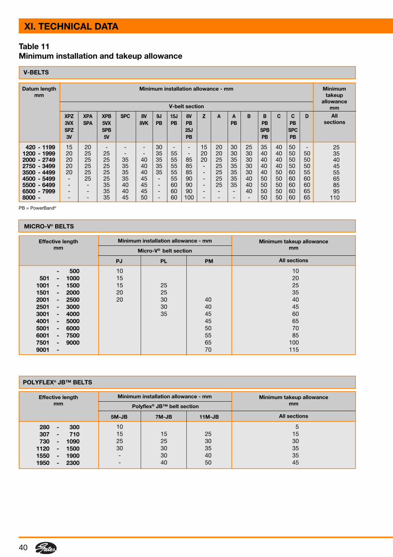
40
10 1015 2015 25 2520 25 3520 30 40 40
30 40 4535 45 60
45 6550 7055 8565 10070 115
10 515 15 25 1525 25 30 3030 30 35 35- 30 40 35- 40 50 45
2535404555658595
110
Table 11Minimum installation and takeup allowance
Allsections
Datum lengthmm
V-belt section
Minimumtakeup
allowancemm
Minimum installation allowance - mm
PJ PL PM
Micro-V® belt section
Minimum installation allowance - mmEffective lengthmm
Minimum takeup allowancemm
All sections
- 500501 - 1000
1001 - 15001501 - 20002001 - 25002501 - 30003001 - 40004001 - 50005001 - 60006001 - 75007501 - 90009001 -
5M-JB 7M-JB 11M-JB
Polyflex® JB™ belt section
Minimum installation allowance - mmEffective lengthmm
Minimum takeup allowancemm
All sections
280 - 300307 - 710730 - 1090
1120 - 15001550 - 19001950 - 2300
XPZ XPA XPB SPC 8V 9J 15J 8V Z A A B B C C D3VX SPA 5VX 8VK PB PB PB PB PB PBSPZ SPB 25J SPB SPC3V 5V PB PB PB
15 20 - - - 30 - - 15 20 30 25 35 40 50 -20 25 25 - - 35 55 - 20 20 30 30 40 40 50 5020 25 25 35 40 35 55 85 20 25 35 30 40 40 50 5020 25 25 35 40 35 55 85 - 25 35 30 40 40 50 5020 25 25 35 40 35 55 85 - 25 35 30 40 50 60 55- 25 25 35 45 - 55 90 - 25 35 40 50 50 60 60- - 35 40 45 - 60 90 - 25 35 40 50 50 60 60- - 35 40 45 - 60 90 - - - 40 50 50 60 65- - 35 45 50 - 60 100 - - - - 50 50 60 65
420 - 11991200 - 19992000 - 27492750 - 34993500 - 44994500 - 54995500 - 64996500 - 79998000 -
PB = PowerBand®
MICRO-V® BELTS
POLYFLEX® JB™ BELTS
V-BELTS
XI. TECHNICAL DATA

41
Belt length Standard installation Installation Installation Tensioningallowance allowance allowance allowance
(flanged pulleys (one pulley flanged) (both pulleys (any drive)removed for flanged)installation)
mm mm mm mm mm
- 1000 1.8 23.8 35.1 0.8
1001 - 1780 2.8 24.6 35.9 0.8
1781 - 2540 3.3 25.1 36.6 1.0
2541 - 3300 4.1 25.9 37.4 1.0
3301 - 4600 5.3 27.1 38.6 1.3
- 1000 1.8 33.0 51.8 0.8
1001 - 1780 2.8 34.0 52.8 0.8
1781 - 2540 3.3 34.5 53.3 1.0
2541 - 3300 4.1 35.3 54.1 1.0
3301 - 4600 5.3 36.5 55.3 1.3
- 500 1.0 14.5 20.0 0.8
501 - 1000 1.3 14.8 20.3 0.8
1001 - 1500 1.8 15.3 20.8 1.0
1501 - 2260 2.3 15.8 21.3 1.3
2261 - 3020 2.8 16.3 21.8 1.3
- 500 1.0 22.6 33.8 0.8
501 - 1000 1.3 22.9 34.1 0.8
1001 - 1500 1.8 23.4 34.6 1.0
1501 - 2260 2.3 23.9 35.1 1.3
2261 - 3020 2.8 24.4 35.6 1.3
3021 - 4020 3.6 25.2 36.4 1.3
4021 - 4780 4.3 25.9 37.1 1.3
4781 - 6860 5.4 27.0 38.2 1.3
- 500 1.0 36.6 59.2 0.8
501 - 1000 1.3 36.9 59.5 0.8
1001 - 1500 1.8 37.4 60.0 1.0
1501 - 2260 2.3 37.9 60.5 1.3
2261 - 3020 2.8 38.4 61.0 1.3
3021 - 4020 3.6 39.2 61.8 1.3
4021 - 4780 4.3 39.9 62.5 1.3
4781 - 6860 5.4 41.0 63.6 1.3
- 500 1.0 48.0 78.5 0.8
501 - 1000 1.3 48.3 78.8 0.8
1001 - 1500 1.8 48.8 79.3 1.0
1501 - 2260 2.3 49.3 79.8 1.3
2261 - 3020 2.8 49.8 80.3 1.3
3021 - 4020 3.6 50.6 81.1 1.3
4021 - 4780 4.3 51.3 81.8 1.3
4781 - 6860 5.4 52.4 82.9 1.3
Table 12Installation & tensioning allowance
PowerGrip® HTD®
5M
PowerGrip® GT5MR
PowerGrip® HTD®
8M
PowerGrip® GT28MGT
PowerGrip® HTD®
14M
PowerGrip® GT214MGT
Poly Chain® GT28MGT
Poly Chain® GT214MGT
PowerGrip® HTD®
20M
SYNCHRONOUS BELTS
XI. TECHNICAL DATA

42
Belt length Standard installation Installation Installation Tensioningallowance allowance allowance allowance
(flanged pulleys (one pulley (both pulleys (any drive)removed for flanged) flanged)installation)
mm mm mm mm mm
90 - 127 0.50 12.20 18.50 0.50
128 - 254 0.75 12.50 18.75 0.75
255 - 508 1.00 12.70 19.00 0.75
509 - 1016 1.30 13.00 19.30 1.00
1017 - 1524 1.80 13.50 19.80 1.30
1525 - 4572 3.10 14.80 21.10 2.10
90 - 127 0.50 16.80 22.10 0.50
128 - 254 0.75 17.00 22.40 0.75
255 - 508 1.00 17.30 22.60 0.75
509 - 1016 1.30 17.60 22.90 1.00
1017 - 1524 1.80 18.10 23.40 1.30
1525 - 4572 3.10 19.40 24.70 2.10
90 - 127 0.50 16.80 24.90 0.50
128 - 254 0.75 17.00 25.20 0.75
255 - 508 1.00 17.30 25.40 0.75
509 - 1016 1.30 17.60 25.70 1.00
1017 - 1524 1.80 18.10 26.20 1.30
1525 - 4572 3.10 19.40 27.50 2.10
90 - 127 0.50 29.50 49.30 0.50
128 - 254 0.75 29.80 49.60 0.75
255 - 508 1.00 30.00 49.80 0.75
509 - 1016 1.30 30.30 50.10 1.00
1017 - 1524 1.80 30.80 50.60 1.30
1525 - 4572 3.10 32.10 51.90 2.10
90 - 127 0.50 39.40 67.80 0.50
128 - 254 0.75 39.70 68.10 0.75
255 - 508 1.00 39.90 68.30 0.75
509 - 1016 1.30 40.20 68.60 1.00
1017 - 1524 1.80 40.70 69.10 1.30
1525 - 4572 3.10 42.00 70.40 2.10
Table 12 (continued)Installation & tensioning allowance
PowerGrip® L
PowerGrip® XL
PowerGrip® H
PowerGrip® XH
PowerGrip® XXH
XI. TECHNICAL DATA

43
Weights and measures
Table 13Estimating belt length from drive components(2 pulleys)
Belt length = 2C + 1.57 (D + d) +
Where: C = shaft centre distance
a) For RMA PowerBand®, PoweRated®, Polyflex® and Micro-V®:
belt length = belt effective lengthD = O.D. of larger pulleyd = O.D. of smaller pulley
b) For Hi-Power®, Super HC®, Super HC® MN, Quad-Power II and metric PowerBand®:
belt length = datum lengthD = datum diameter of larger pulleyd = datum diameter of smaller pulley
c) For synchronous belts:
belt length = pitch lengthD = pitch diameter of larger pulley = N° teeth x pitch/πd = pitch diameter of smaller pulley = N° teeth x pitch/π
(D - d)2
4C
1 lbf = 0.454 kgf
1 lbf = 4.448 N
1 kgf = 9.807 N
1 lbf in = 0.113 Nm
1 ft = 0.3048 m
1 in = 25.4 mm
1 ft2 = 0.093 m2
1 in2 = 645.16 mm2
1 ft3 = 0.028 m3
1 in3 = 16.387 cm3
1 oz = 28.35 g
1 lb = 0.454 kg
1 UK ton = 1.016 ton
1 UK gal = 4.546 litres
1 UK pint = 0.568 litre
1 radian = 57.296 degrees
1 degree = 0.0175 radian
1 HP = 0.746 kW
XI. TECHNICAL DATA

44
XII. SUPPORT
DESIGNFLEX CALCULATION SOFTWAREYou may calculate your own application by means of one of Gates’design manuals or by using DesignFlex, a Windows-basedmultilingual software program. The program is available on CD-ROM(E/20098), but can also be downloaded from Gates’ website atwww.gates.com/europe. The program offers a step-by-step drivecalculation procedure for both V-belts and synchronous belts basedon the criteria and/or limitations specified by the user.DesignFlex runs under Windows 95, 98, 2000, NT or Millennium,requires a Pentium 133 processor or higher and an 800 x 600 screenresolution or higher. A minimum of 32 MB RAM is recommended forsatisfactory calculation speed.
GATES’ APPLICATION ENGINEERSAT YOUR SERVICEIf your application cannot be designed with the aid of Gates’ designmanuals or the DesignFlex software, you can always contact Gates’application engineers. They are at your service to solve even themost difficult drive design problem.
Gates’ application engineers now use DESIGN IQ, a very powerfulsoftware program allowing them to calculate multiple pulley drivesfor the most diverse complex duty cycles. For more information onthis brandnew software possibilities please contact your Gatesrepresentative.
ELECTRONIC PRICE LISTGates’ electronic price list for industrial Power Transmission products isavailable on CD-ROM and enables the user to easily select any productfrom the power transmission range by product number, bar code,description, type, profile and dimension. A full colour photograph and adrawing of the belt profiles complete the information.The information on the CD-ROM is available in six languages.
GATES LITERATUREPlease consult our web site at www.gates.com/europe for specific and updated information on other Gatesindustrial belt products and a list of available literature. Industrial Power Transmission brochures and leafletscan be downloaded from the site. Distributors may link up with the Gates European site supplying visitors withupdated information on the European Gates organisation.

45
ADDRESSES
FRANCEGates S.A.Power Transmission Div.111, rue Francis GarnierB.P. 37F - 58027 Nevers - CedexTl : (33) 3 / 86 71 75 00Fx : (33) 3 / 86 36 62 47
GERMANYGates GmbH AachenEisenbahnweg 50D - 52068 AachenTl : (49) 241 / 5108-0Fx : (49) 241 / 5108-297
OPERATIONS
POLANDGates Polska Sp. z o.o.Ul. Jaworzyµska 301P - 59-220 LegnicaTl : (48) 76 / 855 10 00Fx : (48) 76 / 855 10 01
UKGatesPower Transmission LtdTinwald Downs RoadHeathhall - DumfriesDG1 1TSTl : (44) 1387 / 24 20 00Fx : (44) 1387 / 24 20 10
BELGIUMGates Europe nvDr. Carlierlaan 30B - 9320 ErembodegemTl : (32) 53 / 76 27 11Fx : (32) 53 / 76 27 13
FRANCEGates France S.A.R.L.B.P. 37Zone IndustrielleF - 95380 LouvresTl : (33) 1 / 34 47 41 41Fx : (33) 1 / 34 72 60 54
GERMANYGates GmbH LangenfeldHaus Gravener Straße 191-193D - 40764 LangenfeldTl : (49) 2173 / 795-0Fx : (49) 2173 / 795-150
ITALYGates S.R.L.Via Senigallia 18(Int. 2 - Blocco A - Edificio 1)I - 20161 Milano MITl : (39) 02 / 662 16 21Fx : (39) 02 / 645 86 36
SPAINGates S.A.Polígono IndustrialLes MallolesE - 08660 Balsareny(Barcelona)Tl : (34) 93 / 877 70 00Fx : (34) 93 / 877 70 39
SALES ANDMARKETING FACILITIES
www.gates.com/[email protected]
All Gates’ European Power Transmission Operations are ISO 9001 and ISO 14001 registered.
The manufacturers reserve the right to amend details where necessary. © Gates Europe nv 2004 Printed in Belgium - 01/04.
Important
Every effort has been made to ensure the accuracy and comprehensiveness of the information included in this catalogue.However Gates cannot be held responsible for errors or omissions and for alterations occurred after release for printing;or if Gates products are used in special or exceptional circumstances without prior consultation with and clearancefrom a Gates representative.
This issue is released January 2004 and supersedes all previous versions of this preventive maintenance manual.If your preventive maintenance manual is more than 2 years old, please consult a Gates representative to checkwhether you have the latest version.