industrial and residential applications
TRANSCRIPT
inventions
Article
Storage Gravitational Energy for Small ScaleIndustrial and Residential Applications
Ana Cristina Ruoso 1, Nattan Roberto Caetano 1 and Luiz Alberto Oliveira Rocha 2,*1 Department of Production Engineering, Technology Center, Federal University of Santa Maria, Av.
Roraima 1000, 97105-900 Santa Maria, Brazil; [email protected] (A.C.R.);[email protected] (N.R.C.)
2 Department of Mechanical Engineering, Polytechnic School, University of Vale do Rio dos Sinos, Av.Unisinos 950, 93020-190 São Leopoldo, Brazil
* Correspondence: [email protected]
Received: 27 August 2019; Accepted: 17 October 2019; Published: 31 October 2019�����������������
Abstract: Photovoltaic cells produce electric energy in a short interval during a period of low demandand show high levels of intermittency. One of the well-known solutions is to store the energy andconvert it into a more stable form, to transform again into electricity during periods of high demand, inwhich the energy has a higher value. This process provides economic viability for most energy-storageprojects, even for the least efficient and most common, such as batteries. Therefore, this paper aims topropose a storage system that operates with gravitational potential energy, considering a small-scaleuse. The development of this methodology presents the mathematical modeling of the system andcompares the main characteristics with other systems. The dimensions of the considered system are12-m shaft, 5-m piston height, and 4 m of diameter; it presented an energy storage of 11 kWh. Also,it has an efficiency of about 90%, a lifetime of 50 years, and higher storage densities compared toother systems.
Keywords: solar energy; gravitational energy; storage system
1. Introduction
The production of electricity from renewable sources has grown due to the clean energy policiesin many countries [1,2]. The increased demand for energy, without increasing CO2 emissions andexclusive reliance on finite resources, such as fossil fuels, has made necessary the development ofadvanced renewable energy technologies [3,4]. Many authors have been conducting research to findsolutions for the optimal and quality generation, distribution and use of renewable sources [5–14].
Developments in photovoltaic energy technology lead to lower manufacturing costs, which allowssolar energy to increase its percentage of electricity in the generation matrix [15,16]. Thus, photovoltaicelectricity is one of the best options in comparison to other renewable sources [17,18]. However, solarpower is a variable, intermittent, and generally dispersed source when compared to large-scale powerplants such as hydroelectric and thermoelectric plants [19,20].
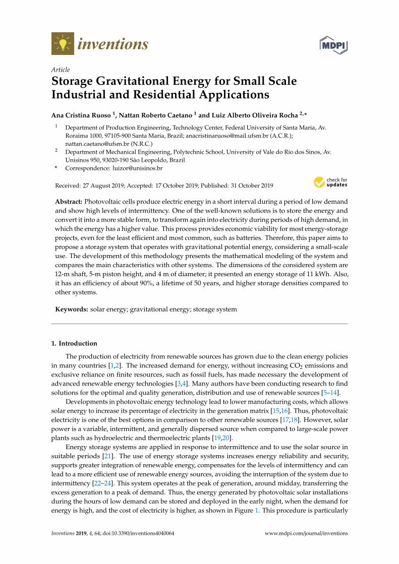
Energy storage systems are applied in response to intermittence and to use the solar source insuitable periods [21]. The use of energy storage systems increases energy reliability and security,supports greater integration of renewable energy, compensates for the levels of intermittency and canlead to a more efficient use of renewable energy sources, avoiding the interruption of the system due tointermittency [22–24]. This system operates at the peak of generation, around midday, transferring theexcess generation to a peak of demand. Thus, the energy generated by photovoltaic solar installationsduring the hours of low demand can be stored and deployed in the early night, when the demand forenergy is high, and the cost of electricity is higher, as shown in Figure 1. This procedure is particularly
Inventions 2019, 4, 64; doi:10.3390/inventions4040064 www.mdpi.com/journal/inventions
Inventions 2019, 4, 64 2 of 13
relevant for the service sector and residential users, for which demand shows considerable changesduring the day [25,26].
Inventions 2019, 4, x 2 of 13
procedure is particularly relevant for the service sector and residential users, for which demand shows considerable changes during the day [25,26].
Figure 1. Energy generation to meet the demand [27].
The potential benefits of integrated network storage technologies include reducing the need for new transmission and generation capacity, improving load, providing a spinning reserve, correcting frequency, voltage and power factors, as well as indirect environmental advantages [28,29].
The energy storage is classified as mechanical, electrochemical, or hydrogen [30]. Electrochemical systems, especially acid batteries, are the most widely used accumulators for storing photovoltaic energy [31,32]. Most research on solar energy storage aims to find an efficient way to store energy, but only considers conventional battery storage. However, battery usage requires a high initial cost, is not cost-effective, does not support high cycling rates, and does not store large amounts of energy in a small volume [33,34]. Besides, there is the impact of metal depletion during battery production, as well as fossil energy consumption and consequent pollution with the use of batteries [35,36].
Each energy storage system has specific characteristics of time response, the limit of stored energy quantity, energy level, charge and discharge cycles, energy density, useful lifetime, efficiency, environmental impact, cost, technological maturity, etc. These characteristics are considered in all energy applications [37,38].
This work applies the principle of gravitational energy for energy storage dedicated exclusively for the storage of photovoltaic solar energy and sized for small industries or residences. Therefore, the mechanism is the same as in other inventions. However, the applications shown in this study consider require novel features that the proposed system has, as was detail explicitly in the paper. Therefore, this work describes a new gravitational potential energy storage system based on existing energy storage principles for a small scale. A review of some mechanical storage methods, especially those using the gravitational potential energy principle, is performed in Section 2, with a comparison in terms of power, energy rating, and round-trip efficiency. Section 3 presents the sizing, and Section 4 presents the dimensions and some characteristics of the proposed storage system. Finally, Section 5 presents the conclusions drawn from the paper.
2. Background
Storage system analysis requires assessing several characteristics, as different renewable resources have unique integration requirements and network services, depending on various details, such as the type and location of the renewable source. This section introduces some mechanical energy storage technologies. However, it mainly addresses one subcategory, the gravitational storage of energy. Thus, it discusses the working principle of these technologies, the limitations, their fundamental characteristics, and the existent literature.
Figure 1. Energy generation to meet the demand [27].
The potential benefits of integrated network storage technologies include reducing the need fornew transmission and generation capacity, improving load, providing a spinning reserve, correctingfrequency, voltage and power factors, as well as indirect environmental advantages [28,29].
The energy storage is classified as mechanical, electrochemical, or hydrogen [30]. Electrochemicalsystems, especially acid batteries, are the most widely used accumulators for storing photovoltaicenergy [31,32]. Most research on solar energy storage aims to find an efficient way to store energy, butonly considers conventional battery storage. However, battery usage requires a high initial cost, is notcost-effective, does not support high cycling rates, and does not store large amounts of energy in asmall volume [33,34]. Besides, there is the impact of metal depletion during battery production, aswell as fossil energy consumption and consequent pollution with the use of batteries [35,36].
Each energy storage system has specific characteristics of time response, the limit of storedenergy quantity, energy level, charge and discharge cycles, energy density, useful lifetime, efficiency,environmental impact, cost, technological maturity, etc. These characteristics are considered in allenergy applications [37,38].
This work applies the principle of gravitational energy for energy storage dedicated exclusivelyfor the storage of photovoltaic solar energy and sized for small industries or residences. Therefore,the mechanism is the same as in other inventions. However, the applications shown in this studyconsider require novel features that the proposed system has, as was detail explicitly in the paper.Therefore, this work describes a new gravitational potential energy storage system based on existingenergy storage principles for a small scale. A review of some mechanical storage methods, especiallythose using the gravitational potential energy principle, is performed in Section 2, with a comparisonin terms of power, energy rating, and round-trip efficiency. Section 3 presents the sizing, and Section 4presents the dimensions and some characteristics of the proposed storage system. Finally, Section 5presents the conclusions drawn from the paper.
2. Background
Storage system analysis requires assessing several characteristics, as different renewable resourceshave unique integration requirements and network services, depending on various details, such as thetype and location of the renewable source. This section introduces some mechanical energy storagetechnologies. However, it mainly addresses one subcategory, the gravitational storage of energy.Thus, it discusses the working principle of these technologies, the limitations, their fundamentalcharacteristics, and the existent literature.
Inventions 2019, 4, 64 3 of 13
Table 1 presents storage technologies, flywheel (FES), compressed air energy storage (CAES),pumped hydroelectric energy storage (PHES), underwater ocean storage systems (UOSS), gravity powermodule (GPM), hydraulic hydro storage (HHS), ground-breaking energy storage (GBES), advancedrail energy storage (ARES), and Gravitricity, as well as their fundamental characteristics: energy rating,power rating, energy density, power density, lifetime, discharge time, and roundtrip efficiency.
Table 1. Technologies of energy storage and systems characteristics. Adapted from [39,40].
StorageTechnology
EnergyDensity
Wh/l
PowerDensity
W/l
Energy RatingWh
Power RatingW
DischargeTime
h
Life Timeyears
RoundtripEfficiency
%
FES 20–80 103–2·103 - <2.5·105 <0.25 15 85–95
CAES 0.4–20 0.04–10 108 5·106–3·108 1–24 20–60 50–89
PHES 0.13–0.5 0.01–0.12 106–2·1010 108–5·109 1–24 40–60 65–87
UOSS - - <109 <109 1–10 n/D 65–90
GPM 1.6 3.13 1.6·109–6.4·109 4·107–1.6·109 1–4 30+ 75–80
HHS - - 109–1010 2·107–2.75·109 1–24 40+ 80
GBES - - <2·1010 108 24 40+ 80
ARES - - <6·109 108–3·109 2–24 40+ 75–86
Gravitricity - - <106 <4·107 <2 50+ 80–90
Flywheel (FES) stores electrical energy in a movable disk in the form of kinetic energy. Thedisc is connected to an electrical machine, which can operate as a generator or in a motor mode. Incharge mode, electrical power flows from the grid to FES, and disk speed increases (engine mode). Indischarge mode, disk speed decreases, and the engine operates in generator mode [41]. FES is rated forspeed, capable of low and high speeds with high and low inertia discs, respectively [42].
This system responds quickly to high power instant demands, has low maintenance costs, highpower density, and storage density that is exceptionally high if compared to other existing storageunits [43]. Limitations of this system are aerodynamic losses, bearing friction losses, shaft position, tiltstabilization, considerable energy loss with the stabilization control system, and high capital cost [44,45].Therefore, the flywheel cannot be used to provide power quality and during long periods, but it isideal for momentary variations.
Compressed air energy storage (CAES) stores large amounts of energy in the form of pressurizedair. In this way, the potential energy of compressed gas (air) is stored in large tanks or undergroundvoids [46,47]. Air pressure increases through electrically driven compressors, which convert electricalenergy into potential energy [48]. Then, when the demand for electricity increases, the pressurized airis heated and then expands in a turbine, which drives a generator for power production. There are twocommercial CAES plants, the Huntorf CAES plant in Germany with a 290 MW air storage gas turbineand also the 110 MW McIntosh CAES plant in Alabama, USA [49].
CAES presents low energy storage density. As such, it requires large storage units but has highstorage capacity and long storage (hours to months) and is therefore suitable for large scale applications.Also, CAES costs between 300–700 euros per kW, which is lower than the cost of PHES and is also lessrestricted by the availability of suitable locations. However, PHES technology is more mature, shows alonger lifetime, and generally has a higher power rating [50,51].
According to Aneke and Wang [39], CAES’s potential round-trip efficiency is 50%–89%; however,in commercial plants, it is around 42%–55%, which is lower than PHES’s. Therefore, although CAES isdeveloped, round-trip efficiency needs optimization. On the other hand, in general, CAES and PHESare the most cost-effective technologies for large-scale storage with frequent cycles.
Pumped hydroelectric storage (PHES) is currently the most widely used storage method, whichcorresponds to over 99% of the world’s bulk energy storage capacity [52]. In short, the system storesenergy in the form of potential energy in a higher water reservoir to which water is pumped during
Inventions 2019, 4, 64 4 of 13
off-peak hours. Water is released to the lower reservoir through turbines to generate electricity duringperiods of high demand.
This system has high energy storage potential, long term storage, and high round-trip efficiency,so it is suitable for large scale applications. However, as in the CAES, the expected efficiency for PHESis 90%, but most commercial installations have a round-trip efficiency of 72%–75% [39].
The low energy density of PHES is one of the limitations that require proper topography, withample water reservoirs and high height variation between them for installation and operation. Thus,the implementation of PHES causes significant environmental impacts, social needs, problems withenvironmental acceptability, and confirmation of the economic viability, which requires high investment.
Underground pumped hydroelectric storage (UPHES) has the same operating principle as theprevious one, but at least one of its reservoirs may be underground. The underground reservoirensures a high vertical displacement without consuming a large surface area. Thus, Menédez et al. [53],Winde et al. [54], and Pujades et al. [55] considered case studies on the implementation of this storagesystem in abandoned mines, where appropriate infrastructure already exists.
The most representative cost of UPHES is underground work, followed by engineering andnetwork connection [56]. According to Meyer [57], hybrid systems are preferable because they estimatethat the costs of above-ground reservoirs are lower than underground ones. The total project cost of aUPHES system has been estimated at 257 million euros, and the cost per kW is 2215 euros [53]; the costof traditional PHES per kW is 500–1700 euros [39]. Although this system has high efficiency, reliability,and availability, economic viability has a high level of uncertainty and needs to be better studied [53].
Underwater ocean storage systems (UOSS) are designed to work with a renewable power plantfloating in the sea (solar or wind energy) [58,59]. The system is a submerged vessel, a reversibleturbine attached to the vessel, and an electrical cable that connects the turbine to the generating unit.Water is pumped out of the vessel during the loading cycle and returns to the vessel when discharged.Cazzaniga et al. [58] scaled a system with a volume of 360 m3 to a depth of 1000 m, and the estimatedstorage capacity was 984 kWh with 90% efficiency. Meanwhile, Slocum et al. [59] presented largerscale systems (some GWh) with 65%–70% efficiency.
Gravity power module (GPM) technology consists of a piston, a water container, and a returnpipe connected to a turbine pump [60,61]. The system operates in a closed circuit while charging asoff-peak electricity is used to drive the engine that transfers water through the return pipe by lifting thepiston on the shaft. While in discharge mode the piston drops, forcing water back through the returnpipe and the turbine that drives the generator, turning the potential energy into electrical energy. Theamount of energy stored by this technology varies with piston size and shaft height. Gravity power’sgoal is to provide power in the 40 MW to 1.6 GW range [60].
GPM and ARES (advanced rail energy storage) are storage technologies suitable for large scaleapplications. They are also suitable for long term storage as they have a low self-discharge rate. Besides,when compared to other gravity storage systems, the GPM has the highest power density, and also hasa high lifetime and efficiency, as shown in Table 1.
The GPM has been studied in many aspects, such as sizing studies by Berrada et al. [27], Loudiyiand Berrada [61] and Berrada et al. [62]. Studies on economic and risk analysis were conducted byBerrada et al. [63–65] and Oldenmenger [66]; GPM viability when combined with another storagesystem was also studied by Berrada et al. [67].
Berrada et al. [63] concluded that the PHES and GPM levelized costs of energy storage (LCOE)were 120 €/MWh and 123 €/MWh, respectively. Also, another work by the same authors on sizingindicated that the storage unloading time was about 368 s. It also concluded that critical systemparameters include flow rate and pressure. On the other hand, the results show that the efficiency ofthe system depends on the sealing material used in the system [62].
These research studies confirm the possibility that GPM has a capital cost per kWh equal to orslightly higher than PHES when fully matured as they are based on a similar concept. Also, if the GPM
Inventions 2019, 4, 64 5 of 13
reaches 75%–80% round-trip efficiency, it may be an excellent alternative to PHES in locations withoutfavorable topography.
Hydraulic hydro storage (HHS) and ground-breaking energy storage (GBES) are similar to GPM,but both are constructed by excavating an area to form a natural piston. The excavated part is connectedto a return pipe and sealed; therefore, its operation is the same as the GPM. In addition to the layoutdifference, HHS and GBES differ in their storage scale ranging from 1 to 20 GWh and have powerratings ranging from 20 MW to 2.75 GW [68–70].
Advanced rail energy storage (ARES) is a rail-based traction drive system that uses surplusrenewable energy or grid electricity to move a mass to a higher altitude by rail. The blocks descend whenthe system is being unloaded, each block weighs about 45–64 t, and a 16 km route is performed [71].The pilot project has a 78%–80% efficiency, no self-discharging storage loss, a lifetime of 40 years, andis located in Tehachapi, California. ARES LLC is building the first commercial project in Nevada: a50 MW power system, 12.5 MWh power capacity, with a 9.3 km path and a 780 t transport mass [72].ARES has topographic limitations as an area with an altitude difference is required for its installation.However, it is an alternative for large-scale applications [72,73].
The storage technology termed Gravitricity is based on vertically raising and lowering a heavymass along an axis in the ground [74,75]. The pistons have a mass of up to 3000 t, and the axles go upto 1500 m deep; these axes can be from existing mines or built axles [74]. The mass is lifted with a cablesystem, similar to the lifting systems used in mines and cranes. Efficiency is about 80%–90%, with aresponse time of about 0.5 h, a lifetime over 50 years, and discharge time up to 2 h, as Table 1.
When compared to other gravity energy storage technologies, the use of overhead weights requiresminimal land use and can make use of existing excavations. Besides, this storage can be combined withcompressed air, by sealing the shaft; space can be used simultaneously as a compressed air pressurevessel, increasing the amount of energy stored by up to three times [74]. Gravitricity received fundingin 2018 to build a prototype of 250 kWh performed in South Africa [76,77].
Deep sea energy storage (MGH) is similar to Gravitricity and eliminates the need for shaftinfrastructure because it uses a floating sea platform to move masses [78]. StratoSolar [79] proposesthe MGH with a photovoltaic power generation system floating on 20-km-high platforms.
The works of Botha and Kamper [40] and Morstyn et al. [80] present the sizing and modeling ofGravitricity storage systems. Botha and Kamper [40] provide the modeling of a gravitational energystorage (GES) system in abandoned mines and analyze two lifting methods, the conventional andelectric machines. GES has energy density between 0.2 and 3.1 Wh/L, power density between 0.3 and30 W/L, energy rating 107 Wh, power rating 2·107 W, discharge time 0.5 h, 50 year lifetime, and 85%round-trip efficiency.
The work of Botha and Kamper [40] indicates that storage capacity is limited by both thesystem height and the piston mass that is hoisted, meaning that it does not have high energy storagelike other gravitational energy-based storage systems. The low energy density combined with lowdischarge time and high power density indicates that GES is best suited for high power and distributedgeneration services.
Morstyn et al. [80] have also designed a gravity energy storage system using suspended weightsfor the development of abandoned mines. In their case study, 340 mine wells could be converted intogravity storage units with capacities higher than 1 MWh, providing 0.804 GWh of energy storage. Thissystem is based on the assumption that the suspended weights are limited to 3000 metric tons and areconstructed using iron ore.
3. Small Scale Energy Storage: Modeling the System
This section presents the proposal of a gravitational storage system and its sizing. This system isbased on the same principle of working as Gravitricity [75], as a solution for improving quality andenergy saving. However, unlike the studies found in the literature and presented in Section 2, this

Inventions 2019, 4, 64 6 of 13
paper aims at small-scale end-use, i.e., small industry and residential use, without the requirement of amine as seen in the works of Botha and Kamper [40] and Morstyn et al. [80].
The system stores renewable energy in the form of gravitational potential energy and the storageis performed by suspending weights. The system is loaded by lifting a piston and discharged during ahigh demand period when the piston is released for descending.
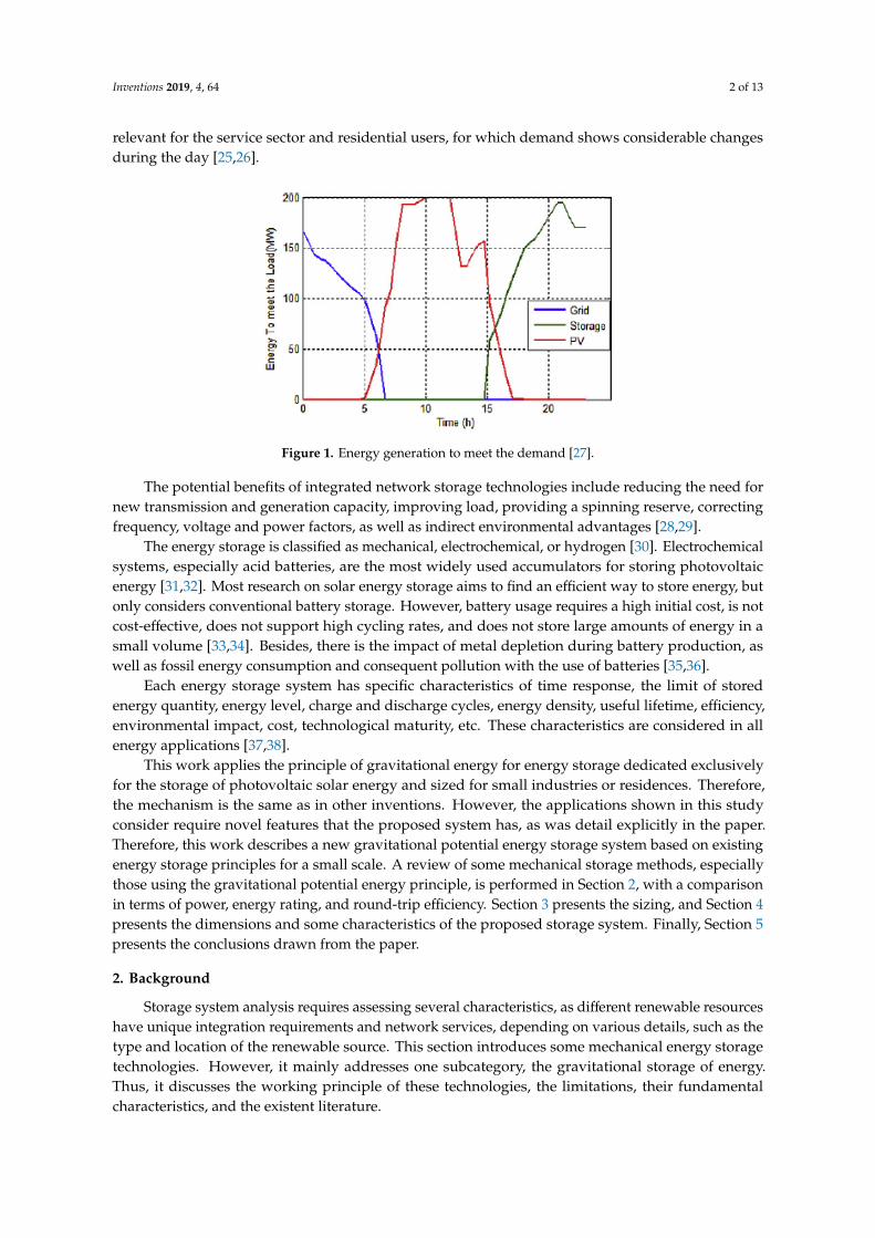
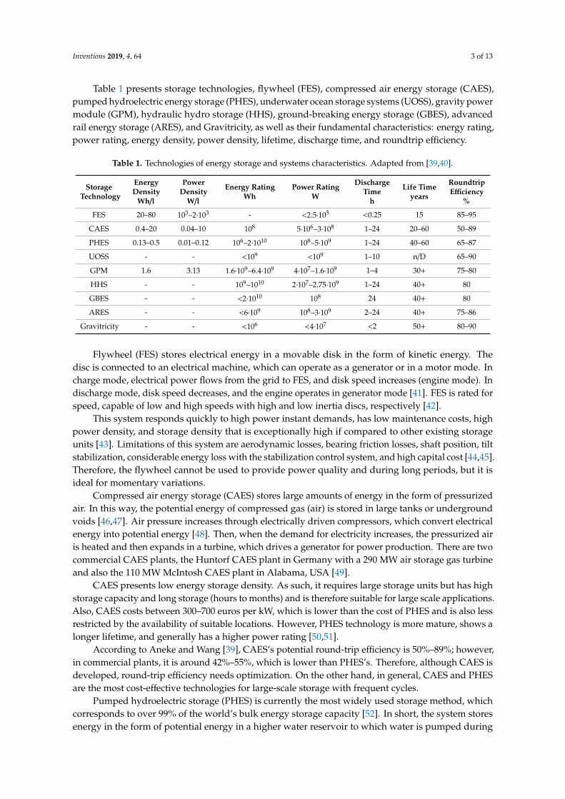
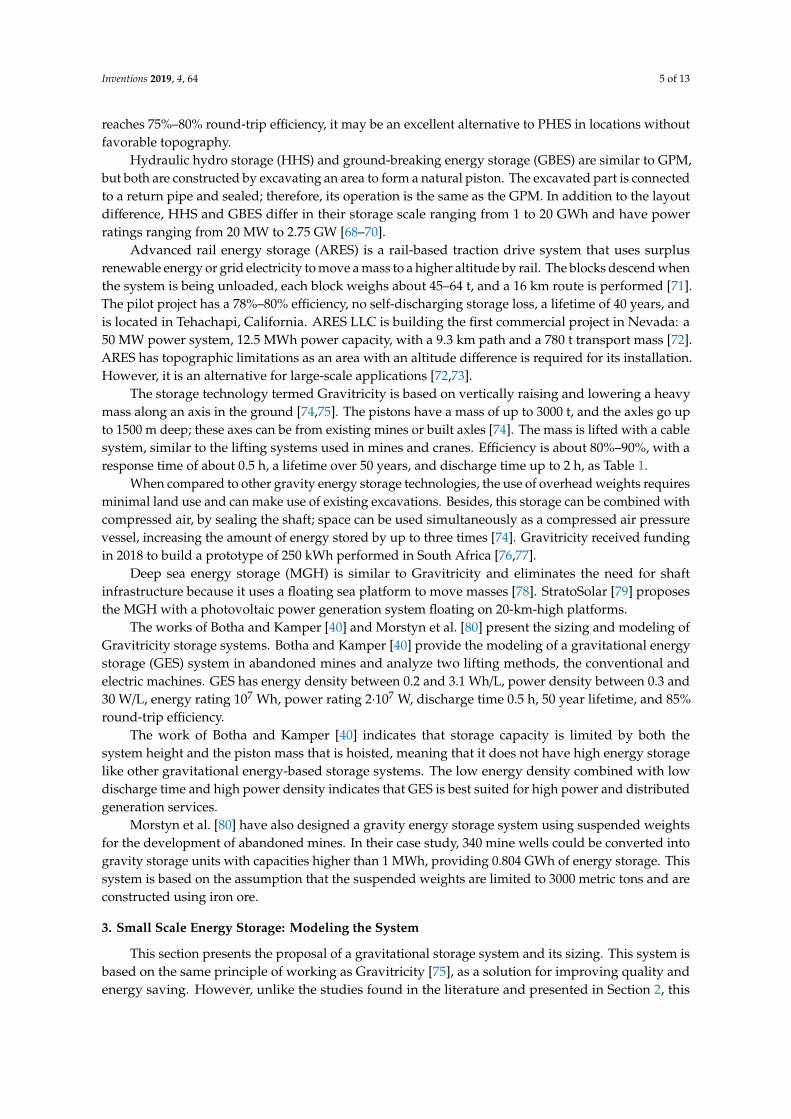
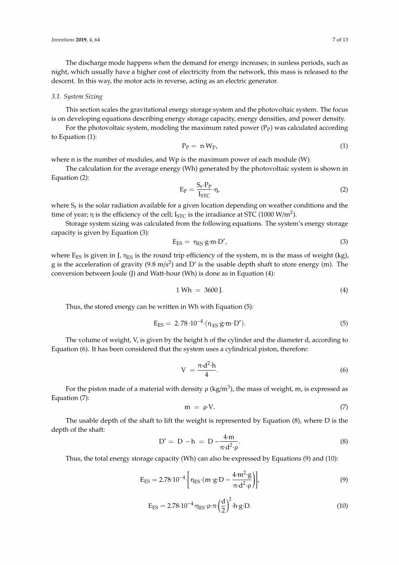
Figure 2 shows the design of the gravity energy storage system consisting primarily of a piston,gears, wire ropes, motor/generator, inverter, and the photovoltaic power generation system. Meanwhile,Figure 3 represents the overall flowchart of system processes.
Inventions 2019, 4, x 6 of 13
The system stores renewable energy in the form of gravitational potential energy and the storage is performed by suspending weights. The system is loaded by lifting a piston and discharged during a high demand period when the piston is released for descending.
Figure 2 shows the design of the gravity energy storage system consisting primarily of a piston, gears, wire ropes, motor/generator, inverter, and the photovoltaic power generation system. Meanwhile, Figure 3 represents the overall flowchart of system processes.
Figure 2. Small scale gravity energy storage system using piston.
In Figure 2, h is the height of the suspended weight, d is the piston diameter, D is the shaft depth, D’ is the usable depth for energy storage, and rs is the radius of the traction sheave. Additional details of the connections and guidance system are provided in the patent filed by Gravitricity [75].
Figure 3 presents the sequence of operation of the proposed system in which, in the sunny period, the photovoltaic panel receives solar radiation, the electrons when affected by this radiation move, and generate an electric current in the panel cells. Electric current, along with voltage, generates power at the photovoltaic cell terminals. An inverter transforms direct current into alternating current for use in the grid.
Figure 3. Simplified flowchart of the energy storage system.
The electrical energy derived from these processes is used in an electric engine, which transforms the electrical energy into mechanical energy that acts on lifting a piston using a pulley system, which aims to facilitate the ascent. As the mass rises, the potential energy increases. When the piston reaches the top, the energy is then stored as mechanical potential energy, and this step is referred to as the system loading mode.
The discharge mode happens when the demand for energy increases; in sunless periods, such as night, which usually have a higher cost of electricity from the network, this mass is released to the descent. In this way, the motor acts in reverse, acting as an electric generator.
Figure 2. Small scale gravity energy storage system using piston.
Inventions 2019, 4, x 6 of 13
The system stores renewable energy in the form of gravitational potential energy and the storage is performed by suspending weights. The system is loaded by lifting a piston and discharged during a high demand period when the piston is released for descending.
Figure 2 shows the design of the gravity energy storage system consisting primarily of a piston, gears, wire ropes, motor/generator, inverter, and the photovoltaic power generation system. Meanwhile, Figure 3 represents the overall flowchart of system processes.
Figure 2. Small scale gravity energy storage system using piston.
In Figure 2, h is the height of the suspended weight, d is the piston diameter, D is the shaft depth, D’ is the usable depth for energy storage, and rs is the radius of the traction sheave. Additional details of the connections and guidance system are provided in the patent filed by Gravitricity [75].
Figure 3 presents the sequence of operation of the proposed system in which, in the sunny period, the photovoltaic panel receives solar radiation, the electrons when affected by this radiation move, and generate an electric current in the panel cells. Electric current, along with voltage, generates power at the photovoltaic cell terminals. An inverter transforms direct current into alternating current for use in the grid.
Figure 3. Simplified flowchart of the energy storage system.
The electrical energy derived from these processes is used in an electric engine, which transforms the electrical energy into mechanical energy that acts on lifting a piston using a pulley system, which aims to facilitate the ascent. As the mass rises, the potential energy increases. When the piston reaches the top, the energy is then stored as mechanical potential energy, and this step is referred to as the system loading mode.
The discharge mode happens when the demand for energy increases; in sunless periods, such as night, which usually have a higher cost of electricity from the network, this mass is released to the descent. In this way, the motor acts in reverse, acting as an electric generator.
Figure 3. Simplified flowchart of the energy storage system.
In Figure 2, h is the height of the suspended weight, d is the piston diameter, D is the shaft depth,D’ is the usable depth for energy storage, and rs is the radius of the traction sheave. Additional detailsof the connections and guidance system are provided in the patent filed by Gravitricity [75].
Figure 3 presents the sequence of operation of the proposed system in which, in the sunny period,the photovoltaic panel receives solar radiation, the electrons when affected by this radiation move, andgenerate an electric current in the panel cells. Electric current, along with voltage, generates power atthe photovoltaic cell terminals. An inverter transforms direct current into alternating current for use inthe grid.
The electrical energy derived from these processes is used in an electric engine, which transformsthe electrical energy into mechanical energy that acts on lifting a piston using a pulley system, whichaims to facilitate the ascent. As the mass rises, the potential energy increases. When the piston reachesthe top, the energy is then stored as mechanical potential energy, and this step is referred to as thesystem loading mode.
Inventions 2019, 4, 64 7 of 13
The discharge mode happens when the demand for energy increases; in sunless periods, such asnight, which usually have a higher cost of electricity from the network, this mass is released to thedescent. In this way, the motor acts in reverse, acting as an electric generator.
3.1. System Sizing
This section scales the gravitational energy storage system and the photovoltaic system. The focusis on developing equations describing energy storage capacity, energy densities, and power density.
For the photovoltaic system, modeling the maximum rated power (PP) was calculated accordingto Equation (1):
PP = n·WP, (1)
where n is the number of modules, and Wp is the maximum power of each module (W).The calculation for the average energy (Wh) generated by the photovoltaic system is shown in
Equation (2):
EP =Sr·PP
ISTC·η, (2)
where Sr is the solar radiation available for a given location depending on weather conditions and thetime of year; η is the efficiency of the cell; ISTC is the irradiance at STC (1000 W/m2).
Storage system sizing was calculated from the following equations. The system’s energy storagecapacity is given by Equation (3):
EES = ηES·g·m·D′, (3)
where EES is given in J, ηES is the round trip efficiency of the system, m is the mass of weight (kg),g is the acceleration of gravity (9.8 m/s2) and D’ is the usable depth shaft to store energy (m). Theconversion between Joule (J) and Watt-hour (Wh) is done as in Equation (4):
1 Wh = 3600 J. (4)
Thus, the stored energy can be written in Wh with Equation (5):
EES = 2. 78 ·10−4·(ηES·g·m·D
′). (5)
The volume of weight, V, is given by the height h of the cylinder and the diameter d, according toEquation (6). It has been considered that the system uses a cylindrical piston, therefore:
V =π·d2·h
4. (6)
For the piston made of a material with density ρ (kg/m3), the mass of weight, m, is expressed asEquation (7):
m = ρ·V. (7)
The usable depth of the shaft to lift the weight is represented by Equation (8), where D is thedepth of the shaft:
D′ = D − h = D −4·m
π·d2·ρ
. (8)
Thus, the total energy storage capacity (Wh) can also be expressed by Equations (9) and (10):
EES = 2.78·10−4·
[ηES·(m ·g·D −
4·m2·g
π·d2·ρ
)], (9)
EES = 2.78·10−4·ηES·ρ·π·
(d2
)2·h·g·D. (10)
Inventions 2019, 4, 64 8 of 13
As the piston height increases and its diameter is kept constant, the mass increases. However, itreduces the usable depth of the shaft, creating a trade-off for energy capacity. Thus, the piston heightshould be as low as possible to increase storage capacity.
As for the wire ropes of the system, it was assumed that the length of the rod (lr) is the sameas the height at which the piston travels (usable depth), i.e., lr = D’. Also, the piston diameter (d) isapproximately the same as the shaft diameter, i.e., d ≈ dshaft. Thus, the system energy density (Wh/m3)can be calculated according to Equation (11):
ρES =EES
Veixo= 2.78·10−4
·ρ·g·h. (11)
Meanwhile, Equation (12) presents the calculation of power density (W/m3):
ρP =ρ·h·g
3.6·103·td, (12)
where td is the storage system unload time in hours. Both energy density and power density dependon piston height (h) and piston material density (ρ). This property is true for any shape as long as theshape of the shaft and piston are the same.
4. Storage System Characteristics and Applications
This section uses the system modeling of Section 3.1 to analyze storage capacity and energy andpower densities that are calculated using different piston materials illustrating the system performance.
The electric motor/generator considered was the model W22 Magnet IR5 Ultra Premium,manufactured by the company WEG. This motor is a synchronous type with high-performancepermanent magnets and has 97% efficiency.
As seen in Table 1 and some studies discussed, this type of storage has a lifetime of 50 years ormore, a response time of less than one second. Round-trip efficiency for the gravity energy storagesystem is considered as 90% according to the Gravitricity system.
The average energy of the photovoltaic system (EP) was estimated at 3 kWh, to meet the demandof a residence. Also, it was considered that the system could be loaded and unloaded once a day.Two materials were selected for the piston: iron, and concrete, with densities of 7850 and 3150 kg/m3,respectively [63,80]. Berrada et al. [63] and Botha and Kamper [40], presented that iron showed betterrelative density and cost ratio when compared to other options.
The use of concrete or iron has been suggested because they are common materials, which arewidely available in the construction of industrial and residential buildings, which are the focus of thisarticle. Thus, these materials can be obtained from wastes or tailings of the construction itself.
With a shaft depth of 12 m, a piston height of 5 m, a diameter of 4 m and a mass and approximately375 metric tons, 11,000 Wh of energy can be stored. The amount of 11,000 Wh corresponds to theenergy required for single household use. Energy and power density are relatively high compared tothose shown in Table 1. A block made of iron yields the energy density of approximately 107 Wh/m3
and power density of 214 W/m3. While with a concrete block the energy density is 43 Wh/m3 and thepower density is 86 W/m3. The discharge time of 0.5 h was considered for the calculations. However,total potential energy storage capacity is affected by the mass block and density variations.
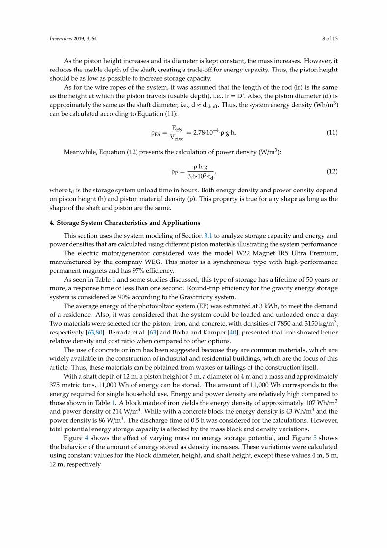
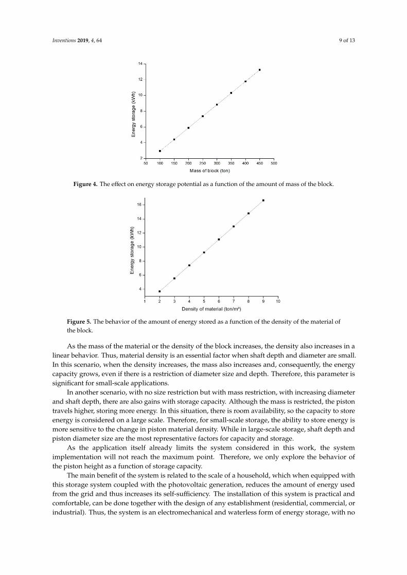
Figure 4 shows the effect of varying mass on energy storage potential, and Figure 5 showsthe behavior of the amount of energy stored as density increases. These variations were calculatedusing constant values for the block diameter, height, and shaft height, except these values 4 m, 5 m,12 m, respectively.
Inventions 2019, 4, 64 9 of 13Inventions 2019, 4, x 9 of 13
Figure 4. The effect on energy storage potential as a function of the amount of mass of the block.
Figure 5. The behavior of the amount of energy stored as a function of the density of the material of the block.
As the mass of the material or the density of the block increases, the density also increases in a linear behavior. Thus, material density is an essential factor when shaft depth and diameter are small. In this scenario, when the density increases, the mass also increases and, consequently, the energy capacity grows, even if there is a restriction of diameter size and depth. Therefore, this parameter is significant for small-scale applications.
In another scenario, with no size restriction but with mass restriction, with increasing diameter and shaft depth, there are also gains with storage capacity. Although the mass is restricted, the piston travels higher, storing more energy. In this situation, there is room availability, so the capacity to store energy is considered on a large scale. Therefore, for small-scale storage, the ability to store energy is more sensitive to the change in piston material density. While in large-scale storage, shaft depth and piston diameter size are the most representative factors for capacity and storage.
As the application itself already limits the system considered in this work, the system implementation will not reach the maximum point. Therefore, we only explore the behavior of the piston height as a function of storage capacity.
The main benefit of the system is related to the scale of a household, which when equipped with this storage system coupled with the photovoltaic generation, reduces the amount of energy used from the grid and thus increases its self-sufficiency. The installation of this system is practical and comfortable, can be done together with the design of any establishment (residential, commercial, or industrial). Thus, the system is an electromechanical and waterless form of energy storage, with no geographical/topographic limitations, such as a mine or water reservoir. Besides, the storage system does not require a connection to the grid.
Figure 4. The effect on energy storage potential as a function of the amount of mass of the block.
Inventions 2019, 4, x 9 of 13
Figure 4. The effect on energy storage potential as a function of the amount of mass of the block.
Figure 5. The behavior of the amount of energy stored as a function of the density of the material of the block.
As the mass of the material or the density of the block increases, the density also increases in a linear behavior. Thus, material density is an essential factor when shaft depth and diameter are small. In this scenario, when the density increases, the mass also increases and, consequently, the energy capacity grows, even if there is a restriction of diameter size and depth. Therefore, this parameter is significant for small-scale applications.
In another scenario, with no size restriction but with mass restriction, with increasing diameter and shaft depth, there are also gains with storage capacity. Although the mass is restricted, the piston travels higher, storing more energy. In this situation, there is room availability, so the capacity to store energy is considered on a large scale. Therefore, for small-scale storage, the ability to store energy is more sensitive to the change in piston material density. While in large-scale storage, shaft depth and piston diameter size are the most representative factors for capacity and storage.
As the application itself already limits the system considered in this work, the system implementation will not reach the maximum point. Therefore, we only explore the behavior of the piston height as a function of storage capacity.
The main benefit of the system is related to the scale of a household, which when equipped with this storage system coupled with the photovoltaic generation, reduces the amount of energy used from the grid and thus increases its self-sufficiency. The installation of this system is practical and comfortable, can be done together with the design of any establishment (residential, commercial, or industrial). Thus, the system is an electromechanical and waterless form of energy storage, with no geographical/topographic limitations, such as a mine or water reservoir. Besides, the storage system does not require a connection to the grid.
Figure 5. The behavior of the amount of energy stored as a function of the density of the material ofthe block.
As the mass of the material or the density of the block increases, the density also increases in alinear behavior. Thus, material density is an essential factor when shaft depth and diameter are small.In this scenario, when the density increases, the mass also increases and, consequently, the energycapacity grows, even if there is a restriction of diameter size and depth. Therefore, this parameter issignificant for small-scale applications.
In another scenario, with no size restriction but with mass restriction, with increasing diameterand shaft depth, there are also gains with storage capacity. Although the mass is restricted, the pistontravels higher, storing more energy. In this situation, there is room availability, so the capacity to storeenergy is considered on a large scale. Therefore, for small-scale storage, the ability to store energy ismore sensitive to the change in piston material density. While in large-scale storage, shaft depth andpiston diameter size are the most representative factors for capacity and storage.
As the application itself already limits the system considered in this work, the systemimplementation will not reach the maximum point. Therefore, we only explore the behavior ofthe piston height as a function of storage capacity.
The main benefit of the system is related to the scale of a household, which when equipped withthis storage system coupled with the photovoltaic generation, reduces the amount of energy usedfrom the grid and thus increases its self-sufficiency. The installation of this system is practical andcomfortable, can be done together with the design of any establishment (residential, commercial, orindustrial). Thus, the system is an electromechanical and waterless form of energy storage, with no

Inventions 2019, 4, 64 10 of 13
geographical/topographic limitations, such as a mine or water reservoir. Besides, the storage systemdoes not require a connection to the grid.
5. Conclusions
This paper presented a new gravity-based energy storage system as a new technology forsmall-scale use. Also, the operating principle and limitations of the different technologies of mechanicalenergy storage were presented, especially those that use gravitational energy. Moreover, thesetechnologies were compared technically, and their applications analyzed.
The proposed system is an electromechanical form which requires minimal land use and does notuse water for its operation, with less stringent geographical requirements than traditional stockpiles.In addition, it has advantages in terms of installation, since it can be installed in buildings and off-grid.This new system has the potential to have high storage density, unloading time on the order ofminutes, a lifetime of 50 years, and efficiency of around 90%, which would optimize power supply andutilization, as well as increase energy self-sufficiency.
The gravitational storage system that uses a piston is a viable and promising storage technology.However, research and studies on feasibility, modeling, sizing, and sensitivity analysis are required togain a more detailed understanding of the challenge involved in the maturity and practical developmentof this proposal. This future work will allow one to accurately compare their features and costs withother existing energy storage options.
Author Contributions: A.C.R.: literature review, construction and editing of the manuscript, acquisition ofresults; N.R.C.: literature review, methodology development, analytical modeling; L.A.O.R.: discussion of results,grammar, spelling and equation review.
Funding: This research received no external funding.
Acknowledgments: The authors acknowledge the Brazilian agencies CNPq (National Council of Technologicaland Scientific Development—Brasília, DF, Brazil), CAPES (Coordination for the Improvement of Higher EducationPersonnel) for the research funding, and the generous assistance of all the people from the company who grantedus access to their database and perception information.
Conflicts of Interest: The authors declare no conflict of interest.
References
1. Ren, G.; Liu, J.; Wan, J.; Guo, Y.; Yu, D. Overview of wind power intermittency: Impacts, measurements, andmitigation solutions. Appl. Energy 2017, 204, 47–65. [CrossRef]
2. Kousksou, T.; Bruel, P.; Jamil, A.; el Rhafiki, T.; Zeraouli, Y. Energy storage, Applications and challenges. Sol.Energy Mater. Sol. Cells 2014, 120, 59–80. [CrossRef]
3. Mohammedi, A.; Rekioua, D.; Rekioua, T.; EddineMebarki, N. Comparative assessment for the feasibility ofstorage bank in small scale power photovoltaic pumping system for building application. Energy Convers.Manag. 2018, 172, 579–587. [CrossRef]
4. Zaouche, F.; Rekioua, D.; Gaubert, J.; Mokrani, Z. Supervision and control strategy for photovoltaic generatorswith battery storage. Int. J. Hydrogen Energy 2017, 42, 19536–19555. [CrossRef]
5. Ruoso, A.C.; Bitencourt, L.C.; Sudati, L.U.; Klunk, M.A.; Caetano, N.R. New Parameters for the ForestBiomass Waste Ecofirewood Manufacturing Process Optimization. Periódico Tchê Química 2019, 16, 560–571.
6. Cataluña, R.; Shah, Z.; Venturi, V.; Caetano, N.R.; da Silva, B.P.; Azevedo, C.M.N.; Silva, R.; Suarez, P.A.Z.;Oliveira, L.P. Production process of di-amyl ether and its use as an additive in the formulation of aviationfuels. Fuel 2018, 228, 226–233. [CrossRef]
7. Caetano, N.R.; Venturini, M.S.; Centeno, F.R.; Lemmertz, C.K.; Kyprianidis, K.G. Assessment of mathematicalmodels for prediction of thermal radiation heat loss from laminar and turbulent jet non-premixed flames.Therm. Sci. Eng. Prog. 2018, 7, 241–247. [CrossRef]
8. Venturini, M.S.; Bageston, J.V.; Caetano, N.R.; Peres, L.V.; Bencherif, H.; Schuch, N.J. Mesopause regiontemperature variability and its trend in southern Brazil. Ann. Geophys. 2018, 36, 301–310. [CrossRef]
9. Klunk, M.; Damiani, L.H.; Feller, G.; Rey, M.F. Geochemical modeling of diagenetic reactions in Snorre Fieldreservoir sandstones: A comparative study of computer codes. Braz. J. Geol. 2015, 45, 29–40. [CrossRef]
Inventions 2019, 4, 64 11 of 13
10. Caetano, N.R.; Silva, B.P. Technical and Economic Viability for the Briquettes Manufacture. Defect Diffus.Forum 2017, 380, 218–226.
11. Caetano, N.R.; Stapasolla, T.Z.; Peng, F.B.; Schneider, P.S.; Pereira, F.M.; Vielmo, A.H. Diffusion FlameStability of Low Calorific Fuels. Defect Diffus. Forum 2015, 362, 29–37. [CrossRef]
12. Caetano, N.R.; Da Silva, L.F.F. A comparative experimental study of turbulent non premixed flames stabilizedby a bluff-body burner. Exp. Therm. Fluid Sci. 2015, 63, 20–33. [CrossRef]
13. Caetano, N.R.; Cataluña, R.; Vielmo, H.A. Analysis of the Effect on the Mechanical Injection Engine UsingDoped Diesel Fuel by Ethanol and Bio-Oil. Int. Rev. Mech. Eng. 2015, 9, 124–128. [CrossRef]
14. Caetano, N.R.; Soares, D.; Nunes, R.P.; Pereira, F.M.; Schneider, P.S.; Vielmo, H.A.; van der Laan, F.T. Acomparison of experimental results of soot production in laminar premixed flames. Open Eng. 2015, 5.[CrossRef]
15. Reddy, S.S. Optimal scheduling of thermal-wind-solar power system with storage. Renew. Energy 2017, 101,1357–1368. [CrossRef]
16. Grzesiak, W. Innovative system for energy collection and management integrated within a photovoltaicmodule. Sol. Energy 2016, 132, 442–452. [CrossRef]
17. Ju, X.; Xu, C.; Hu, Y.; Han, X.; Wei, G.; Du, X. A review on the development of photovoltaic/concentratedsolar power (PV-CSP) hybrid systems. Sol. Energy Mater. Sol. Cells 2017, 161, 305–327. [CrossRef]
18. Cataluña, R.; Shah, Z.; Pelisson, L.; Caetano, N.R.; Da Silva, R.; Azevedo, C. Biodiesel Glycerides from theSoybean Ethylic Route Incomplete Conversion on the Diesel Engines Combustion Process. J. Braz. Chem. Soc.2017. [CrossRef]
19. Ondeck, A.D.; Edgar, T.F.; Baldea, M. Impact of rooftop photovoltaics and centralized energy storage on thedesign and operation of a residential CHP system. Appl. Energy 2018, 222, 280–299. [CrossRef]
20. Suberu, M.Y.; Mustafa, M.W.; Bashir, N. Energy storage systems for renewable energy power sector integrationand mitigation of intermittency. Renew. Sustain. Energy Rev. 2014, 35, 499–514. [CrossRef]
21. Singh, S.; Singh, M.; Kaushik, S.C. Feasibility study of an islanded microgrid in rural area consisting of PV,wind, biomass and battery energy storage system. Energy Convers. Manag. 2016, 128, 178–190. [CrossRef]
22. Akbari, H.; Browne, M.C.; Ortega, A.; Huang, M.J.; Hewitt, N.J.; Norton, B.; McCormack, S.J. Efficient energystorage technologies for photovoltaic systems. Sol. Energy 2018. [CrossRef]
23. Castillo, A.; Gayme, D.F. Grid-scale energy storage applications in renewable energy integration, A survey.Energy Convers. Manag. 2014, 87, 885–894. [CrossRef]
24. Jallouli, R.; Krichen, L. Sizing, techno-economic and generation management analysis of a stand alonephotovoltaic power unit including storage devices. Energy 2012, 40, 196–209. [CrossRef]
25. Akinyele, D.O.; Rayudu, R.K. Review of energy storage technologies for sustainable power networks. Sustain.Energy Technol. Assess. 2014, 8, 74–91. [CrossRef]
26. Parastegari, M.; AllahHooshmand, R.; Khodabakhshian, A.; HosseinZar, A. Joint operation of wind farm,photovoltaic, pump-storage and energy storage devices in energy and reserve markets. Int. J. Electr. PowerEnergy Syst. 2015, 64, 275–284. [CrossRef]
27. Berrada, A.; Loudiyi, K.; Garde, R. Dynamic modeling of gravity energy storage coupled with a PV energyplant. Energy 2017, 134, 323–335. [CrossRef]
28. Gonzatti, F.; Farret, F.A. Mathematical and experimental basis to model energy storage systems composed ofelectrolyzer, metal hydrides and fuel cells. Energy Convers. Manag. 2017, 132, 241–250. [CrossRef]
29. Rohit, A.K.; Rangnekar, S. An overview of energy storage and its importance in Indian renewable energysector: Part II—Energy storage applications, benefits and market potential. J. Energy Storage 2017, 13, 447–456.[CrossRef]
30. Dostál, Z.; Ladányi, L. Demands on energy storage for renewable power sources. J. Energy Storage 2018, 18,250–255. [CrossRef]
31. Aissou, S.; Rekioua, D.; Mezzai, N.; Rekioua, T.; Bacha, S. Modeling and control of hybrid photovoltaic windpower system with battery storage. Energy Convers. Manag. 2015, 89, 615–625. [CrossRef]
32. Amirante, R.; Cassone, E.; Distaso, E.; Tamburran, P. Overview on recent developments in energy storage,Mechanical, electrochemical and hydrogen technologies. Energy Convers. Manag. 2017, 132, 372–387.[CrossRef]
33. Balcombe, P.; Rigby, D.; Azapagic, A. Investigating the importance of motivations and barriers related tomicrogeneration uptake in the UK. Appl. Energy 2014, 130, 403–418. [CrossRef]

Inventions 2019, 4, 64 12 of 13
34. McKenna, E.; McManus, M.; Cooper, S.; Thomson, M. Economic and environmental impact of lead-acidbatteries in grid-connected domestic PV systems. Appl. Energy 2013, 104, 239–249. [CrossRef]
35. Mcmanus, M.C. Environmental consequences of the use of batteries in low carbon systems: The impact ofbattery production. App. Energy 2012, 93, 288–295. [CrossRef]
36. Hawkes, A.D. Estimating marginal CO2 emissions rates for national electricity systems. Energy Policy 2010,38, 5977–5987. [CrossRef]
37. Azhgaliyeva, D. Energy Storage and Renewable Energy Deployment, Empirical Evidence from OECDcountries. Energy Procedia 2019, 158, 3647–3651. [CrossRef]
38. Rosa, F.S.; Padilha, A.; Caetano, N.R. Inventory Management: A case study applied in a hospital pharmacy.Espacios 2016, 37, 22.
39. Aneke, M.; Wang, M. Energy storage technologies and real life applications—A state of the art review. Appl.Energy 2016, 179, 350–377. [CrossRef]
40. Botha, C.D.; Kamper, M.J. Capability study of dry gravity energy storage. J. Energy Storage 2019, 23, 159–174.[CrossRef]
41. Lan, H.; Bai, Y.; Wen, S.; Yu, D.; Hong, Yi.; Dai, J.; Cheng, P. Modeling and stability analysis of hybridpv/diesel/ess in ship power system. Inventions 2016, 1, 5. [CrossRef]
42. Arani, A.A.K.; Zaker, B.; Gharehpetian, G.B. A control strategy for flywheel energy storage system forfrequency stability improvement in islanded microgrid. Iran. J. Electr. Electron. Eng. 2017, 13, 10–21.
43. Jayasinghe, S.G.; Meegahapola, L.; Fernando, N.; Jin, Z.; Guerrero, J.M. Review of ship microgrids: Systemarchitectures, storage technologies and power quality aspects. Inventions 2017, 2, 4. [CrossRef]
44. Šonský, J.; Tesar, V. Design of a stabilised flywheel unit for efficient energy storage. J. Energy Storage 2019, 24,100765. [CrossRef]
45. Arani, A.A.K.; Gharehpetian, G.B.; Abedi, M. Review on energy storage systems control methods inmicrogrids. Int. J. Electr. Power Energy Syst. 2019, 107, 745–757. [CrossRef]
46. Barnes, F.S.; Levine, J.G. Large Energy Storage Systems Handbook; CRC Press: Boca Raton, FL, USA, 2011.47. Matos, C.R.; Carneiro, J.F.; Silva, P.P. Overview of large-scale underground energy storage technologies for
integration of renewable energies and criteria for reservoir identification. J. Energy Storage 2019, 21, 241–258.[CrossRef]
48. He, W.; Luo, X.; Evans, D.; Busby, J.; Garvey, S.; Parkes, D.; Wang, J. Exergy storage of compressed air incavern and cavern volume estimation of the large-scale compressed air energy storage system. Appl. Energy2017, 208, 745–757. [CrossRef]
49. Budt, M.; Wolf, D.; Span, R.; Yan, J. A review on compressed air energy storage: Basic principles, pastmilestones and recent developments. Appl. Energy 2016, 170, 250–268. [CrossRef]
50. Wang, J.; Lu, K.; Ma, L.; Wang, J.; Dooner, M.; Miao, S.; Jian, L.; Wang, D. Overview of compressed air energystorage and technology development. Energies 2017, 10, 991. [CrossRef]
51. Wang, J.; Ma, L.; Lu, K.; Miao, S.; Wang, D.; Wang, J. Current research and development trend of compressedair energy storage. Syst. Sci. Control Eng. 2017, 5, 434–448. [CrossRef]
52. Rehman, S.; Al-Hadhrami, L.M.; MahbubAlam, M. Pumped hydro energy storage system: A technologicalreview. Renew. Sustain. Energy Rev. 2015, 44, 586–598. [CrossRef]
53. Menéndez, J.; Ordóñez, A.; Álvarez, R.; Loredo, J. Energy from closed mines: Underground energy storageand geothermal applications. Renew. Sustain. Energy Rev. 2019, 108, 498–512. [CrossRef]
54. Winde, F.; Kaiser, F.; Erasmus, E. Exploring the use of deep level gold mines in South Africa for undergroundpumped hydroelectric energy storage schemes. Renew. Sustain. Energy Rev. 2017, 78, 668–682. [CrossRef]
55. Pujades, E.; Orban, P.; Bodeux, S.; Archambeau, P.; Erpicum, S.; Dassargues, A. Underground pumpedstorage hydroelectricity using abandoned works (deep mines or open pits) and the impact on groundwaterflow. Hydrogeol. J. 2016, 24, 1531–1546. [CrossRef]
56. Wong, I.H. An underground pumped storage scheme in the Bukit Timah granite of Singapore. Tunn. Undergr.Space Tech. 1996, 11, 485–489. [CrossRef]
57. Meyer, F. Storing Wind Energy Underground; FIZ Karlsruhe–Leibnz Institute for Information Infrastructure:Eggenstein Leopoldshafen, Germany, 2013.
58. Cazzaniga, R.; Cicua, M.; Marrana, T.; Rosa-Clot, M.; Rosa-Clota, P.; Tina, G.M. DOGES, Deep oceangravitational energy storage. J. Energy Storage 2017, 14, 264–270. [CrossRef]
Inventions 2019, 4, 64 13 of 13
59. Slocum, A.H.; Fennell, G.E.; Dundar, G.; Hodder, B.G.; Meredith, J.D.C. Ocean renewable energy storage(ORES) system: Analysis of an undersea energy storage concept. Proc. IEEE 2013, 101, 906–924. [CrossRef]
60. Gravity Power–Grid Scale Energy Storage, 2017. Available online: http://www.gravitypower.net/ (accessedon 1 July 2019).
61. Loudiyi, K.; Berrada, A. Experimental Validation of Gravity Energy Storage Hydraulic Modeling. EnergyProcedia 2017, 134, 845–854. [CrossRef]
62. Berrada, A.; Loudiyi, K.; Zorkani, I. Dynamic modeling and design considerations for gravity energy storage.J. Clean. Prod. 2017, 159, 336–345. [CrossRef]
63. Berrada, A.; Loudiyi, K.; Zorkani, I. System design and economic performance of gravity energy storage. J.Clean. Prod. 2017, 156, 317–326. [CrossRef]
64. Berrada, A.; Loudiyi, K.; Zorkani, I. Profitability, risk, and financial modeling of energy storage in residentialand large scale applications. Energy 2017, 119, 94–109. [CrossRef]
65. Berrada, A.; Loudiyi, K.; Zorkani, I. Valuation of energy storage in energy and regulation markets. Energy2016, 115, 1109–1118. [CrossRef]
66. Oldenmenger, A.W. Highrise Energy Storage Core: Feasibility Study for a Hydro-Electrical Pumped EnergyStorage System in a Tall Building. Master’s Thesis, Delft University of Technology, Delft, Holland, 2013.
67. Berrada, A.; Loudiyi, K.; Zorkani, I. Toward an improvement of gravity energy storage using compressed air.Energy Procedia 2017, 134, 855–864. [CrossRef]
68. Escovale Consultancy Services. 2016. Available online: http://www.escovale.com/GBES.php (accessed on 1July 2019).
69. Escombe, F. GBES—Ground-Breaking Energy Storage (GBES-01). 2016. Available online: http://www.escovale.com/downloads/GBES-01-Introduction.pdf (accessed on 1 July 2019).
70. Heindl Energy Storage. 2019. Available online: https://heindl-energy.com (accessed on 1 July 2019).71. Letcher, T.M.; Law, R.; Reay, D. Storing Energy: With Special Reference to Renewable Energy Sources; Oxford:
Elsevier: Oxford, UK, 2016.72. Ares. The Power of Gravity. 2019. Available online: https://www.aresnorthamerica.com/ (accessed on 1
July 2019).73. Sandru, O. Gravel Energy Storage System Funded by Bill Gates, the Green Optimistic. 2012. Available online:
www.greenoptimistic.com (accessed on 1 July 2019).74. Blair, C. Gravitricity–Storing Power as Well as Energy. 2016. Available online: http://www.all-energy.co.uk/
Conference/Download-2016-Presentations/ (accessed on 1 July 2019).75. Gravitricity. 2019. Available online: https://www.gravitricity.com/ (accessed on 1 July 2019).76. Bungane, B. Gravitricity Sets Sights on South Africa to Test Green Energy Tech. 2018. Available online: https:
//www.esi-africa.com/gravitricity-sets-sights-south-africa-test-green-energy-tech/ (accessed on 1 July 2019).77. Huisman. Gravitricity Teams up with Worldwide Lifting, Drilling and Subsea Specialists Huisman to
Build Prototype Energy Store. 2018. Available online: https://www.huismanequipment.com/ (accessed on 1July 2019).
78. MGH–Deep Sea Energy Storage. 2015. Available online: http://www.mgh-energy.com/ (accessed on 1July 2019).
79. Stratosolar. 2019. Available online: http://www.stratosolar.com/ (accessed on 1 July 2019).80. Morstyn, T.; Chilcott, M.; Mcculloch, M.D. Gravity Energy Storage with Suspended Weights for Abandoned
Mine Shafts. Appl. Energy 2019, 239, 201–206. [CrossRef]
© 2019 by the authors. Licensee MDPI, Basel, Switzerland. This article is an open accessarticle distributed under the terms and conditions of the Creative Commons Attribution(CC BY) license (http://creativecommons.org/licenses/by/4.0/).