industrial adoption of model-based systems engineering
TRANSCRIPT
Purdue UniversityPurdue e-Pubs
Open Access Theses Theses and Dissertations
January 2015
Industrial Adoption of Model-Based SystemsEngineering: Challenges and StrategiesApoorv MaheshwariPurdue University
Follow this and additional works at: https://docs.lib.purdue.edu/open_access_theses
This document has been made available through Purdue e-Pubs, a service of the Purdue University Libraries. Please contact [email protected] foradditional information.
Recommended CitationMaheshwari, Apoorv, "Industrial Adoption of Model-Based Systems Engineering: Challenges and Strategies" (2015). Open AccessTheses. 1151.https://docs.lib.purdue.edu/open_access_theses/1151

Graduate School Form 30 Updated 1/15/2015
PURDUE UNIVERSITY GRADUATE SCHOOL
Thesis/Dissertation Acceptance
This is to certify that the thesis/dissertation prepared
By
Entitled
For the degree of
Is approved by the final examining committee:
To the best of my knowledge and as understood by the student in the Thesis/Dissertation Agreement, Publication Delay, and Certification Disclaimer (Graduate School Form 32), this thesis/dissertation adheres to the provisions of Purdue University’s “Policy of Integrity in Research” and the use of copyright material.
Approved by Major Professor(s):
Approved by: Head of the Departmental Graduate Program Date
Apoorv Maheshwari
Industrial Adoption of Model-Based Systems Engineering: Challenges and Strategies
Master of Science in Aeronautics and Astronautics
Dr. Daniel A. DeLaurentisChair
Dr. Jitesh Panchal
Dr. Nathan Hartman
Dr. Daniel A. DeLaurentis
Dr. Steven H. Collicott 12/7/2015

INDUSTRIAL ADOPTION OF MODEL-BASED SYSTEMS ENGINEERING:
CHALLENGES AND STRATEGIES
A Thesis
Submitted to the Faculty
of
Purdue University
by
Apoorv Maheshwari
In Partial Fulfillment of the
Requirements for the Degree
of
Master of Science in Aeronautics and Astronautics
December 2015
Purdue University
West Lafayette, Indiana

ii
Dedicated to my parents.

iii
ACKNOWLEDGMENTS
I would like to express the deepest appreciation to my advisor, Professor Daniel
A. DeLaurentis, for his constant support to my work. His guidance and command on
the topic helped me stay on track in the research work. I could not have imagined
having a better advisor and mentor for my Master’s thesis.
Besides my advisor, I would like to thank the rest of my thesis committee: Prof.
Jitesh Panchal, Prof. Nathan Hartman, and Prof. Robert Kenley, for their insightful
comments and encouragement, and also for the precise questions which incented me
to widen my research from various perspectives.
My sincere thanks also goes to the INCOSE Biomedical Healthcare Challenge
Team, who provided me with an opportunity to work on the interesting infusion pump
design problem. Without their precious support and expertise, it would not have been
possible to understand medical standards, let alone integrate the information with
the model-based process representations.
Finally, I would like to thank my peers and friends within the SoS Lab and the
Purdue University for all the stimulating discussions and good memories.

iv
TABLE OF CONTENTS
Page
LIST OF TABLES . . . . . . . . . . . . . . . . . . . . . . . . . . . . . . . . vi
LIST OF FIGURES . . . . . . . . . . . . . . . . . . . . . . . . . . . . . . . vii
ABSTRACT . . . . . . . . . . . . . . . . . . . . . . . . . . . . . . . . . . . ix
PUBLICATIONS . . . . . . . . . . . . . . . . . . . . . . . . . . . . . . . . . xi
1 Introduction . . . . . . . . . . . . . . . . . . . . . . . . . . . . . . . . . . 11.1 MBSE: An Overview . . . . . . . . . . . . . . . . . . . . . . . . . . 21.2 MBSE: Status Quo . . . . . . . . . . . . . . . . . . . . . . . . . . . 41.3 Challenges in adoption of MBSE by industry - Premiere to the Case
Studies . . . . . . . . . . . . . . . . . . . . . . . . . . . . . . . . . . 6
2 Not just a Diagramming Tool! . . . . . . . . . . . . . . . . . . . . . . . . 92.1 Science of Integration . . . . . . . . . . . . . . . . . . . . . . . . . . 92.2 Translation Framework . . . . . . . . . . . . . . . . . . . . . . . . . 122.3 Aspects of SysML and Agent-based Representations . . . . . . . . . 15
2.3.1 Viewpoints . . . . . . . . . . . . . . . . . . . . . . . . . . . 162.3.2 SysML Networks . . . . . . . . . . . . . . . . . . . . . . . . 18
2.4 Interfacing SysML Specifications to Agent-based Simulation . . . . 192.5 The NextGen Air Traffic Control System of Systems . . . . . . . . . 212.6 Results of the Simulation . . . . . . . . . . . . . . . . . . . . . . . . 282.7 Lessons Learned . . . . . . . . . . . . . . . . . . . . . . . . . . . . . 30
3 Tackling the Regulatory Issues . . . . . . . . . . . . . . . . . . . . . . . . 313.1 Introduction to the Engineering Design of Systems . . . . . . . . . . 313.2 Healthcare Case Study . . . . . . . . . . . . . . . . . . . . . . . . . 32
3.2.1 Introduction . . . . . . . . . . . . . . . . . . . . . . . . . . . 333.2.2 Process Diagrams . . . . . . . . . . . . . . . . . . . . . . . . 33
3.3 Lessons Learned . . . . . . . . . . . . . . . . . . . . . . . . . . . . . 42
4 UAV Design Case Study . . . . . . . . . . . . . . . . . . . . . . . . . . . 434.1 Introduction . . . . . . . . . . . . . . . . . . . . . . . . . . . . . . . 434.2 System-level Design Activities . . . . . . . . . . . . . . . . . . . . . 43
4.2.1 Problem Definition . . . . . . . . . . . . . . . . . . . . . . . 434.2.2 Functional Decomposition . . . . . . . . . . . . . . . . . . . 444.2.3 Physical Architecture Design . . . . . . . . . . . . . . . . . . 464.2.4 Architecture Allocation . . . . . . . . . . . . . . . . . . . . . 46

v
Page
4.2.5 Interface Architecture Development . . . . . . . . . . . . . . 484.2.6 Qualification System Development . . . . . . . . . . . . . . 49
4.3 Airfoil Analysis using XFOIL . . . . . . . . . . . . . . . . . . . . . 494.3.1 Demonstration . . . . . . . . . . . . . . . . . . . . . . . . . 50
4.4 Lessons Learned . . . . . . . . . . . . . . . . . . . . . . . . . . . . . 54
5 Conclusions and Future Work . . . . . . . . . . . . . . . . . . . . . . . . 555.1 Conclusions . . . . . . . . . . . . . . . . . . . . . . . . . . . . . . . 555.2 Future Work . . . . . . . . . . . . . . . . . . . . . . . . . . . . . . . 56
5.2.1 Short-term . . . . . . . . . . . . . . . . . . . . . . . . . . . . 565.2.2 Long-term . . . . . . . . . . . . . . . . . . . . . . . . . . . . 57
REFERENCES . . . . . . . . . . . . . . . . . . . . . . . . . . . . . . . . . . 59
A SysML diagrams for the Healthcare Case Study . . . . . . . . . . . . . . 63
B Traditional Top-Down Systems Engineering (TTDSE) and Platform-BasedDesign (PBD) . . . . . . . . . . . . . . . . . . . . . . . . . . . . . . . . . 75
VITA . . . . . . . . . . . . . . . . . . . . . . . . . . . . . . . . . . . . . . . 77

vi
LIST OF TABLES
Table Page
2.1 Similarities between SysML and agent-based modeling . . . . . . . . . 17
vii
LIST OF FIGURES
Figure Page
1.1 Transition to Model-based Approach in Different Domains [11] . . . . . 4
2.1 Evolution of product development from the Drawing Board to Model-Based Engineering [35] . . . . . . . . . . . . . . . . . . . . . . . . . . . 10
2.2 The PLM Circle [36] . . . . . . . . . . . . . . . . . . . . . . . . . . . . 11
2.3 Model Based Design . . . . . . . . . . . . . . . . . . . . . . . . . . . . 12
2.4 Behavioral model of an agent (adapted from [39]) . . . . . . . . . . . . 13
2.5 Translation Framework for SysML to ABM . . . . . . . . . . . . . . . . 15
2.6 Translation Mechanism . . . . . . . . . . . . . . . . . . . . . . . . . . . 20
2.7 Activity Diagram for Aircraft agent . . . . . . . . . . . . . . . . . . . . 25
2.8 Logical Network . . . . . . . . . . . . . . . . . . . . . . . . . . . . . . . 25
2.9 Physical Network . . . . . . . . . . . . . . . . . . . . . . . . . . . . . . 26
2.10 Parametric diagram for DAF agent file generation . . . . . . . . . . . . 26
2.11 ParaMagic instance browser for agent file generation . . . . . . . . . . 27
2.12 DAF Simulation Results . . . . . . . . . . . . . . . . . . . . . . . . . . 29
3.1 Systems Engineering “Vee” Diagram [48] . . . . . . . . . . . . . . . . . 32
3.2 The Navigation Page . . . . . . . . . . . . . . . . . . . . . . . . . . . . 35
3.3 Development Phases - Block Definition Diagram . . . . . . . . . . . . . 36
3.4 Information flow across different Development Phases . . . . . . . . . . 37
3.5 Perform Systems Engineering . . . . . . . . . . . . . . . . . . . . . . . 38
3.6 Allocated Architecture Development - Block Definition Diagram . . . . 39
3.7 Activity Flow Diagram for Allocated Architecture Development . . . . 40
3.8 Mapping Buede’s diagrams with ISO 14971 . . . . . . . . . . . . . . . 41
4.1 Mission Scenario . . . . . . . . . . . . . . . . . . . . . . . . . . . . . . 44
4.2 Model-based Representation of the Requirements . . . . . . . . . . . . 45

viii
Figure Page
4.3 Functional Decomposition of the UAV system . . . . . . . . . . . . . . 46
4.4 Physical Architecture for the Lift System . . . . . . . . . . . . . . . . . 47
4.5 Decomposition of Physical Design of a Fixed Wing . . . . . . . . . . . 48
4.6 Modified Translation Framework . . . . . . . . . . . . . . . . . . . . . 50
4.7 Snippet from the generated MATLAB file . . . . . . . . . . . . . . . . 51
4.8 Snapshot of the XFOIL Analysis . . . . . . . . . . . . . . . . . . . . . 52
4.9 Final XFOIL Analysis Results . . . . . . . . . . . . . . . . . . . . . . . 53
A.1 Main Navigation Page . . . . . . . . . . . . . . . . . . . . . . . . . . . 63
A.2 Block Definition Diagram of the Development Phases . . . . . . . . . . 64
A.3 Information Flow Across the Development Phases . . . . . . . . . . . . 65
A.4 Perform Systems Engineering - Block Definition Diagram . . . . . . . . 66
A.5 System-level Design Activities - Block Definition Diagram . . . . . . . 66
A.6 Information Flow Across System-level Design Activities . . . . . . . . . 67
A.7 Problem Definition - Block Definition Diagram . . . . . . . . . . . . . . 68
A.8 Information Flow During Problem Definition . . . . . . . . . . . . . . . 69
A.9 Functional Architecture Development - Block Definition Diagram . . . 70
A.10 Physical Architecture Design - Block Definition Diagram . . . . . . . . 70
A.11 Allocated Architecture Development - Block Definition Diagram . . . . 71
A.12 Information Flow During Architecture Allocation . . . . . . . . . . . . 72
A.13 Interface Architecture Development - Block Definition Diagram . . . . 73
A.14 Qualification System Development - Block Definition Diagram . . . . . 73
A.15 Mapping process diagrams with ISO 14971 . . . . . . . . . . . . . . . . 74
B.1 PBD Process [62] . . . . . . . . . . . . . . . . . . . . . . . . . . . . . . 75

ix
ABSTRACT
Maheshwari, Apoorv M.S.A.A., Purdue University, December 2015. Industrial Adop-tion of Model-Based Systems Engineering: Challenges and Strategies. Major Pro-fessor: Daniel A. DeLaurentis.
As design teams are becoming more globally integrated, one of the biggest chal-
lenges is to efficiently communicate across the team. The increasing complexity and
multi-disciplinary nature of the products are also making it difficult to keep track of
all the information generated during the design process by these global team mem-
bers. System engineers have identified Model-based Systems Engineering (MBSE) as
a possible solution where emphasis is placed on the application of visual modeling
methods and best practices to systems engineering (SE) activities right from the be-
ginning of the conceptual design phases through to the end of the product lifecycle.
Despite several advantages, there are multiple challenges restricting the adoption of
MBSE by industry. We mainly consider the following two challenges: a) Industry per-
ceives MBSE just as a diagramming tool and does not see too much value in MBSE;
b) Industrial adopters are skeptical if the products developed using MBSE approach
will be accepted by the regulatory bodies. To provide counter evidence to the for-
mer challenge, we developed a generic framework for translation from an MBSE tool
(Systems Modeling Language, SysML) to an analysis tool (Agent-Based Modeling,
ABM). The translation is demonstrated using a simplified air traffic management
problem and provides an example of a potential quite significant value: the ability
to use MBSE representations directly in an analysis setting. For the latter challenge,
we are developing a reference model that uses SysML to represent a generic infusion
pump and SE process for planning, developing, and obtaining regulatory approval of
a medical device. This reference model demonstrates how regulatory requirements
can be captured effectively through model-based representations. We will present

x
another case study at the end where we will apply the knowledge gained from both
case studies to a UAV design problem.

xi
PUBLICATIONS
1. Maheshwari, A., Kenley, C. R., & DeLaurentis, D. A. (2015, October). Cre-
ating Executable AgentBased Models Using SysML. In INCOSE International
Symposium (Vol. 25, No. 1, pp. 1263-1277).
2. Maheshwari, A., Lott, M., Malins, R., Waterplas, C., Stein, J., Thukral, A.,
Kenley, C. R., & DeLaurentis, D. A. Application of systems engineering to
regulatory compliance activities for medical devices. In 9th Great Lakes Regional
Conference 2015. International Council on Systems Engineering (INCOSE).
(Oral Presentation)

1
1. Introduction
The origin of Systems Engineering (SE) as we know it today can be traced back to
Ludwig von Bertalanffy [1] when he defined system as a ‘whole’ consisting of interact-
ing ‘parts’. Wymore, who is considered one of the founding fathers of SE, defined it as
“the intellectual, academic, and professional discipline, the primary concern of which
is the responsibility to ensure that all the requirements for a bioware/hardware/software
system are satisfied throughout the lifecycle of the system.” [2] Today, SE is defined in
different forms by different organizations. Keating et al. [3] provides a good overview
of different perspectives of SE. Three commonly used definitions of SE are as follows:
SE is an interdisciplinary approach and means to enable the realization
of successful systems. It focuses on defining customer needs and required
functionality early in the development cycle, documenting requirements,
and then proceeding with design synthesis and system validation while
considering the complete problem: operations, cost and schedule, per-
formance, training and support, test, manufacturing, and disposal. (IN-
COSE) [4]
SE is a discipline that concentrates on the design and application of the
whole (system) as distinct from the parts. It involves looking at a problem
in its entirety, taking into account all the facets and all the variables and
relating the social to the technical aspects. (FAA) [5]
SE is a methodical, disciplined approach for the design, realization, tech-
nical management, operations, and retirement of a system. A system is a
construct or collection of different elements that together produce results
not obtainable by the elements alone. (NASA) [6]

2
The common recurring theme is that SE is an iterative approach that supports the
complete life-cycle of the product and involves understanding interaction between
sub-systems.
Over the years, SE gave us a number of important tools, including Quality Function
Deployment (QFD) [7] [8], and Universal Systems Language (USL) [9], which rev-
olutionized the engineering fields by designing systems with significantly increased
reliability and productivity along with lowering the risk. Today, we stand at another
such junction, where systems engineers have identified another approach, Model-
Based Systems Engineering (MBSE), which can help us design better in the complex
world.
1.1 MBSE: An Overview
A model is a representation of information that follows some specific guidelines
and semantics. MBSE is defined by International Council on Systems Engineering
(INCOSE), in their SE Vision 2020 [10], as follows:
MBSE is the formalized application of modeling to support system re-
quirements, analysis, verification, and validation activities beginning in
the conceptual design phase and continuing throughout development and
later life-cycle phases.
Thus, in simple words, MBSE is a more digital and visual approach to represent
the SE processes. The main aim of the MBSE is to enhance the ability to capture,
analyze, share and manage the system information. MBSE is often represented as
a shift from document-centric to a model-centric approach to SE. In a traditional
document-centric approach, information associated with different SE processes, such
as specifications, interface requirements, system descriptions, analysis reports, trade-
off studies and qualification processes, are contained in documents. In a model-
centric approach, all of (or a part of) this information is captured in a model or
a set of models. The author believes that this approach will result in significant
3
improvements in the system design process due to the following advantages of MBSE
over traditional SE:
• Improved communication: The model-based representations will improve
the communication across the system stakeholders, within the project teams
and across the spoken language barriers. It will help in reducing the loss of
information due to the language differences.
• Improved complexity management: With the ability to view the system
from different perspectives and to trace the impact of changes across the system
design, it becomes easier to manage the complexity of the system.
• Improved understanding: Information can be captured in more standard-
ized ways by creating logical models of the system. These models will help in
providing a high of level of abstraction, enabling design reuse or sharing and
thus, resulting in reduced cycle times and lower design costs.
• Improved design of test cases: With clearer representations of the system,
it will be easier to identify the weaknesses in the system. For example, an
improved understanding of information flow in a large complex system will help
us in identifying the most critical sub-systems quickly.
• Easier verification: It will be easier to evaluate an unambiguous and precise
system model for consistency, correctness, and completeness. This will also help
in leveling of requirements to understand which requirement is more critical (or
less critical) to the system design.
Before moving forward, it is important to understand that creating models to
represent a system is not a new concept. In fact, this concept exists at the heart
of scientific research where we constantly try to represent natural processes in forms
of theories or equations. This evolution to model-based approach has happened in
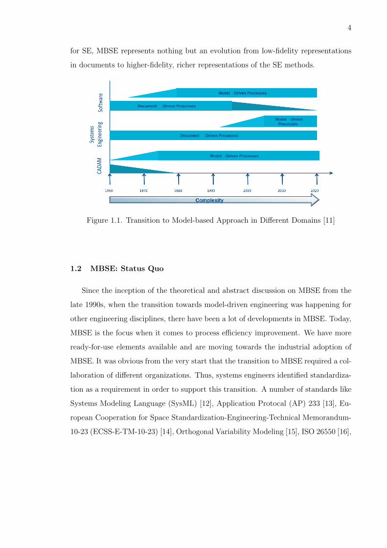
other domains in the past and will happen in the future as well (Figure 1.1). Thus,
4
for SE, MBSE represents nothing but an evolution from low-fidelity representations
in documents to higher-fidelity, richer representations of the SE methods.
Figure 1.1. Transition to Model-based Approach in Different Domains [11]
1.2 MBSE: Status Quo
Since the inception of the theoretical and abstract discussion on MBSE from the
late 1990s, when the transition towards model-driven engineering was happening for
other engineering disciplines, there have been a lot of developments in MBSE. Today,
MBSE is the focus when it comes to process efficiency improvement. We have more
ready-for-use elements available and are moving towards the industrial adoption of
MBSE. It was obvious from the very start that the transition to MBSE required a col-
laboration of different organizations. Thus, systems engineers identified standardiza-
tion as a requirement in order to support this transition. A number of standards like
Systems Modeling Language (SysML) [12], Application Protocal (AP) 233 [13], Eu-
ropean Cooperation for Space Standardization-Engineering-Technical Memorandum-
10-23 (ECSS-E-TM-10-23) [14], Orthogonal Variability Modeling [15], ISO 26550 [16],

5
etc., have been developed since then. These standards are constantly developing while
initial deployment has also started in parallel. We will discuss SysML in detail later.
Other than the standards, a lot of progress has been made in the development
and application of MBSE in both academia and industry. We summarize major
ongoing research in this area here. The author encourages interested readers to go
through [17] [18] [19] to learn about more ongoing projects in MBSE.
Dave [20] provides a good summary of the ongoing MBSE work at the NASA
Jet Propulsion Laboratory (JPL). JPL has been working on developing and applying
MBSE to various systems engineering problems across different project types, activ-
ities and life-cycle phases. They have applied MBSE to approximately 20 different
projects including Mars 2020, Orion, The Jupiter Europa Orbiter, Europa Clipper,
The Soil Moisture Active Passive, etc. For example, they have used model-based
system representations to help in design exploration across architectural variants for
a fractionated spacecraft. They identified that MBSE was really useful in capturing
a rich set of rules and constraints that characterize a produce-able architecture or a
set of architectural variants.
While the JPL is working on the implementation of MBSE, Peak et al. [21] lists
how academic institutions have been working on educating the community through
graduate and professional courses on MBSE. For example, the MBSE Center [22],
along with the industrial partners, have been using SysML as their specific implemen-
tation mechanism to teach MBSE concepts to the students and working professionals.
Buede [23] in his book The Engineering Design of Systems takes a model-based
approach to key SE activities and introduces models and methods using a lot of ex-
amples from diverse domains. London [24] envisions a framework which can combine
MBSE with best practices to generate and evaluate concepts more efficiently.
MBSE is gradually being adopted among big industrial companies as well. Boeing
has been stressing on educating people about the concepts of MBSE for sometime
now. They have been using the MBSE approach in an integrated data environment to
support Integrated Product Architectures (IPA) incentive at Boeing. IPA is aimed at
6
developing and deploying a common capability to enable Boeing engineers to integrate
requirements, architectures, and analyses [25].
Rolls Royce, another major aerospace company, has also been exploring the MBSE
for past few years with the focus on implementing different standards in their engi-
neering processes. In their implementation, they have observed that with MBSE there
has been a 20%-40% reduction in the number of requirements. Also, MBSE has been
helpful in early verifiability and validation of the products [11].
The work on MBSE adoption is not only limited to the aerospace sector and has
been picked up in the consumer packaged goods industry as well. Procter & Gamble
have identified MBSE as a means to create persistent, traceable and reusable require-
ments over product and process life cycles. They are using SystemicaTM Systems
Engineering Methodology for their work [26].
It is evident that the interest in MBSE is growing among the big industrial players.
This is also observed in the various surveys done by INCOSE on assessing the adoption
of the modeling in the systems engineering community since 2009 [27] [28] [29] [30]. It
was observed in the latest survey results that the MBSE adoption has increased in the
non-DoD/Defense industries such as Energy, Rail and Automotive when compared
with previous survey results. Still almost 50% of the responses come from people
representing companies from defense sector. The awareness about the MBSE pilots
and adoption of MBSE has also increased over the years. Along with identifying the
MBSE awareness, the survey also asked the responders to list major challenges in the
MBSE adoption in the industry. We discuss these challenges in detail in the next
section.
1.3 Challenges in adoption of MBSE by industry - Premiere to the Case
Studies
With the help of the survey results [30], literature [31] [32] [33] and interactions
with industry members [25] [26] [11], a number of roadblocks on the path of indus-
7
trial adoption of MBSE have been identified. We categorize these challenges in the
following broad categories:
1. Tools and Methodologies Issues: The industrial perception is that MBSE
is just another diagramming tool which represents data in a more organized
manner at a higher-level but provides no benefit in the later phases of product
design like analysis, etc. For example, one of the survey respondents [30] said
that, “the fact that MBSE models cannot convert directly into simulation really
stinks”. Thus, to change the industrial perception, it is important to develop
the ability to translate MBSE design representations to analysis models.
2. Regulatory Issues: The regulatory system is still mainly document-based
and thus, industrial adopters are skeptical if the products developed using the
MBSE approach will be acceptable by the regulatory bodies. To tackle this
challenge, we need to show that the regulatory requirements can be captured
at the same level (or even better) in the model-based representations.
3. Legacy Issues: Most companies have significant legacy product data existing
in document-centric approach. But there is no simple (or inexpensive) trans-
lation process to convert that information to the model-centric format. This
presents a big hurdle for the companies to apply MBSE to the existing products.
4. Cost/Return on Investment Issues: It is difficult to measure the impact of
MBSE on the product design. Thus, it is often asked if the investment in MBSE
is worth the cost incurred in the implementation. Development cost-per-project
can be one such metric to measure the impact of MBSE. An independent study
done by Embedded Market Forecasters, based on 667 respondents, showed that
model-based approaches cost 55% less and slightly improve on-time delivery
when compared with traditional SE approaches [34].
5. Lack of Skilled Practitioners: Another major inhibiting factor is the lack
of MBSE-skilled practitioners in the industry who can not only execute the

8
model-based projects but also educate management or fellow practitioners in
other parts of the adoption curve than early adopters. This challenge can be
tackled by increasing the number of MBSE-educating centers (like GaTech) and
also, by demonstrating the value of MBSE through more case studies.
Among the aforementioned challenges, we will focus on the following two research
questions in our work:
• What are the features of an effective framework for translating model-based con-
ceptual representations to analysis models?
• What are the specific products in a typical model based representation that, when
properly formed, could be used to satisfy the regulatory requirements? And do
these model based representations provide any benefit over the document-based
approach?
In Chapter 2, we will propose and demonstrate a translation framework to trans-
late a model-based representation to an agent-based simulation model. We will also
discuss some of the challenges associated with the proposed framework. In Chapter 3,
we will apply a model-based design methodology to a safety-critical biomedical device
and represent regulatory requirements using model-based approach. In Chapter 4, we
will revisit the framework suggested in the Chapter 2 and modify it to handle some
of the identified challenges. We will demonstrate the modified framework through
a UAV design case study while adapting and implementing the process explained in
the Chapter 3. Finally, we conclude with the insights gained through the work and
suggest some future research directions in the Chapter 5.

9
2. Not just a Diagramming Tool!
Simulation plays an important role in the analysis of alternatives during the early
phases of systems engineering activities. In this chapter, we try to identify the features
of the framework that can translate model-based representations to analysis models
effectively. We develop and demonstrate a generic framework to translate a SysML
conceptual model to an executable agent-based simulation model using a simplified
air traffic management problem. Along with the potential advantages, we also identify
major challenges and possible mismatches in accomplishing a suitable translation for
real-world complex systems.
2.1 Science of Integration
Product Lifecycle Management (PLM) is defined as the process of managing the
entire lifecycle of a product from requirements identification, through design and
manufacture, to service and disposal of manufactured products. In the current state,
PLM and MBSE can be considered as two different approaches to product develop-
ment which have evolved from different requirements. PLM is the evolution of the
Product Data Management (PDM) approach, which was suggested to manage and
track the creation, change and archive of all product-related information. The PDM
concept was extended in PLM to manage all information around a manufactured
product throughout its lifecycle. On the other hand, MBSE is being developed to
advance the practice of SE with an objective to produce a more complete, consistent
and feasible system specification upon which the product can be built. Due to these
different requirements, PLM has evolved into a system that supports the manage-
ment of document variants, change processes and product configuration but lacks in
the transportation of semantic, computer-interpretable information throughout the

10
Figure 2.1. Evolution of product development from the DrawingBoard to Model-Based Engineering [35]
lifecycle whereas MBSE can model the semantic information of a product but lacks in
managing it throughout the lifecycle. Thus, to realize the complete potential of both
PLM and MBSE approaches, the new generation PLM must itself be Model-Based
by incorporating more structured information with meaning and follow a stronger
model-based approach than it does today. This integration of PLM and MBSE is
commonly referred to as Model-Based Engineering as shown in the Figure 2.1.
Boeing identifies the current lack of integration of MBSE representations with
the phases and tools downstream to the design representation as one of the major
roadblocks in the industrial adoption of MBSE [25]. Figure 2.2, usually referred to
as the PLM Circle, shows the different phases of the product lifecycle. The current
MBSE literature is more focused and developed on the first two stages of this PLM
circle, namely, Requirements representation and Design representation. The MBSE
representations are also quite developed to represent the process going from the re-
quirements phase to the design phase. The main challenge exists in going from the

11
Figure 2.2. The PLM Circle [36]

12
design phase to the following analysis phase. Without this link, it is very difficult to
realize the actual potential of the well-organized MBSE representations. Figure 2.3
is another representation of the model-based design process. It stresses more on how
the link between the analysis and standard design library-based representations will
lead into the further stages of the product lifecycle management. In this chapter, we
will focus on the area (and the arrow) marked in green (Fig. 2.3). Connecting the
model-based design representations with the analysis tools is the first step towards
the integration of MBSE with PLM.
Figure 2.3. Model Based Design
2.2 Translation Framework
Kenley et al. [37] reviewed agent-based simulation models for systems of systems
and MBSE methods that are applicable to specifying a system of systems. Their
agent-based models are built from executable MATLAB code that simulates an al-
13
located system-of-systems architecture where each function is modeled as an agent
operating in a network of multiple, independent interacting agents [38]. The models
simulate their functionality and operational effects, such as computational and com-
munications latency, that are a consequence of the physical properties of the allocated
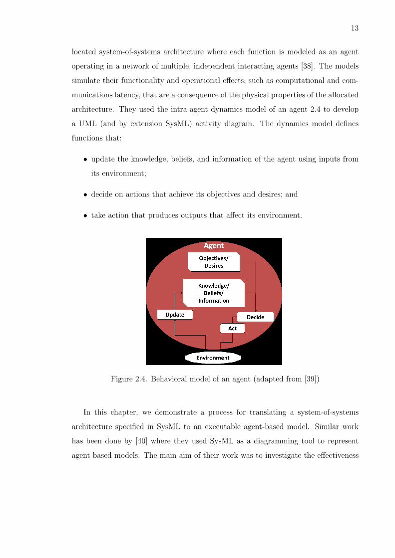
architecture. They used the intra-agent dynamics model of an agent 2.4 to develop
a UML (and by extension SysML) activity diagram. The dynamics model defines
functions that:
• update the knowledge, beliefs, and information of the agent using inputs from
its environment;
• decide on actions that achieve its objectives and desires; and
• take action that produces outputs that affect its environment.
Figure 2.4. Behavioral model of an agent (adapted from [39])
In this chapter, we demonstrate a process for translating a system-of-systems
architecture specified in SysML to an executable agent-based model. Similar work
has been done by [40] where they used SysML as a diagramming tool to represent
agent-based models. The main aim of their work was to investigate the effectiveness

14
of SysML in establishing a conceptual model for agent-based modeling. However,
in our research, we use SysML models to define the system and we seek to add
a use by extracting information useful for agent-based simulation. Designing for
Adaptability and evolutioN in System of systems Engineering (DANSE) project which
has been working on developing methodology to support evolutionary, adaptive, and
iterative lifecycles for systems of systems is another example where SysML models
are combined with tabular data to automatically generate architecture variants for
system analysis.
The generic schematic for translation from SysML to a simulation model is shown
in Figure 2.5. This schematic is similar to the work of McGinnis et al. [41], who
apply a model-driven architecture approach to develop a discrete event simulation
from a SysML model of semiconductor manufacturing. Two distinct domain-specific
toolboxes are mentioned in Figure 2.5. The domain-specific toolbox on the left is ded-
icated to the description of conceptual models using SysML whereas the toolbox on
the right is the tool that is used to create an agent-based simulation model. The mid-
dle part consisting of three ovals represents the steps to achieve this translation. The
first step is to understand the conceptual similarities and differences in how SysML
and agent-based models represent the key aspects of a system of systems, namely, sys-
tem definition and system inter-dependencies. These aspects are discussed in Section
2.3. The next step is to understand mappings between the domain-specific toolboxes.
To achieve this, we need to understand the interface between SysML specifications
and the agent-based model. This interface is discussed in Section 2.4. Once the map-
ping between the domain-specific toolboxes is completely understood, the final step
is to translate the conceptual model prepared using SysML to an executable agent-
based model. This translation is explained using a simple example in Section 2.5.
The demonstration problem centers on a system of systems for air traffic control that
was represented in SysML and interfaced with an executable agent-based modeling
code written in MATLAB that simulates the operational activities of the system of
systems.

15
Figure 2.5. Translation Framework for SysML to ABM
2.3 Aspects of SysML and Agent-based Representations
The Systems Modeling Language, commonly known as SysML, has been specif-
ically developed for model-based systems engineering to formalize the change from
document-based to a model-based form of organization of information. It is a general-
purpose modeling language, supporting the specification, analysis, design, verifica-
tion, and validation of systems.
Agent-based modeling is a modeling approach to simulate the simultaneous ac-
tions and interactions of multiple autonomous agents (individual or collective) and
understand the effects of the combined actions and interactions on the system as a
whole. By allowing a designer to visualize these effects, it becomes possible to un-
derstand the root causes of the effects and to improve the modeled system. With its
bottom-up approach, agent-based modeling is flexible in adapting to new architec-
tures by integrating or removing any physical component or functional capability from
the system. These advantages make agent-based modeling a very useful modeling and
simulation approach for systems of systems.
An agent-based model represents a system of systems using four basic elements:

16
1. Agents/Objects: The set of all simulated or passive heterogeneous entities
that interact with the environment based on their interaction rules.
2. Space: The environment where agents and objects are located and signals
propagate. The space can be both discrete and continuous.
3. Time: The system evolves over time. The system can evolve over both discrete
and continuous time intervals. For most of engineering problems, time can be
considered as one of the dimensions of the environment.
4. Dynamics: The interaction rules and behaviors of all the agents that determine
their actions and changes in state.
McGinnis et al. [41] identify a growing need for translating a conceptual model
(such as the one created in SysML) directly to a simulation program to formalize and
automate a substantial portion of the implementation side of the simulation process.
Schonherr et al. [42] tried to build SysML models after identifying and structuring
the significant properties of discrete processes mainly for production systems. IBM’s
Haifa Research Lab uses a generic SysML-based methodology for improving the archi-
tectural design phase [43]. In this chapter, we identify the key elements of SysML, viz.
viewpoints and network representations, which can be used to map SysML models to
agent-based simulations. We also demonstrate the translation with an agent-based
simulation from the air traffic management domain.
2.3.1 Viewpoints
SysML defines four set of viewpoints - structural, behavioral, requirements, and
parametric. The structural viewpoint defines the elements (including the composition
of systems, their properties, and organizational grouping) of the systems using the
block definition diagram and the internal block diagram. The behavioral viewpoint
explains the interaction and architecture of the system using activity, sequence, state
machine, and use case diagrams. The requirements viewpoint functions as a require-

17
Table 2.1. Similarities between SysML and agent-based modeling
Viewpoints SysML Agent-Based Modeling
Structural Element definition Agent definition
BehavioralInteraction and architecture of the
system
Information flow between
the agents
Requirements Requirement management toolVerification of agent-based
model (indirect)
ParametricLogical/mathematical constraints
on the design
Parameters of intra-agent
dynamics
ments management tool keeping all the requirements in one place, making it easier
for a systems engineer to create, relate, trace, and analyze them. Finally, the para-
metric viewpoint explains the constraints on the design via logical and mathematical
expressions.
For agent-based modeling, structural viewpoints serve as the basis of defining
various agents being simulated. Properties of the elements defined in the SysML
can be directly mapped as the agent properties in the simulation. The behavioral
viewpoint maps to the interaction and information flow between and within the agents
in the simulation. The requirements viewpoint can be indirectly associated with
verifying and analyzing the outcomes of the simulation but cannot be directly mapped
with the functioning of the agent-based model. Finally, the parametric viewpoint
defines the parameters of intra-agent dynamics for every agent. These similarities are
summarized in the Table 2.1.
Though the congruence between the SysML viewpoints and the corresponding
agent-based viewpoints seems significant, mismatches are possible. One of the major
advantages of agent-based modeling is its ability to easily create multiple instances
of an agent and analyze their interaction. In SysML, although it is possible to create
multiple instances of the same element, it becomes relatively difficult to manage the
links and the interactions once the number of instances becomes high. Another possi-

18
ble mismatch may occur in the ability to trigger a particular event at a specific point
in time. Since SysML viewpoints are static representations of different components
of the system, it is difficult to trigger events dynamically in the simulation using
SysML. State machines can be used to represent various event triggers in SysML but
proper extraction of the information relevant for agent-based simulation has not been
achieved yet.
2.3.2 SysML Networks
Another important feature of SysML is its representation of networks. SysML
can represent two types of architectures (or networks) used in cyber-physical design:
logical and physical [44]. Logical network architectures describe the exchange of
information between systems by explaining what information is transferred between
systems. The physical network architecture shows the connectivity of systems by
explaining the physical paths over which the information is transferred. For example,
a logical network connection may specify that - when the driver presses the brake
pedal, the information to slow down the car flows in the system. The related physical
network would show the hydraulic configuration which is transferring the information
from the brake pedal to the road-wheel brakes. The combination of these two types
of links articulates that the brake pedal transfers information to slow down the car
to the brakes using hydraulics, where both the action and the medium may have
differing properties. Keeping these two networks separate allows for changes to either
network without necessarily altering the other. For example, both the foot brake and
the parking brake have the same logical networks but different physical networks. The
driver just knows that the car will slow down by pressing the brake pedal and thus,
the driver only knows about the logical network. The driver does not need to know
about the underlying physical network to interact with the system. Similarly, in an
agent-based model, this distinction between the path of interaction and the medium
of interaction can help in modeling the system in a more generic way. Moreover, it

19
also presents an opportunity to analyze the effects of different logical and physical
concepts separately.
In an agent-based model, an agent changes its state based on its internal logical
relations and external stimuli. Thus, an agent-based model represents these networks
by specifying the interaction rules and the information flow for the agents. The
distinction between a logical and a physical network surely helps in understanding
the problem in a greater depth but this distinction might not be readily visible in an
agent-based model at times. In those situations, direct translation of SysML networks
to agent-based dynamics can be problematic (or, at worse, completely incorrect).
2.4 Interfacing SysML Specifications to Agent-based Simulation
After understanding the system-of-systems representation from the perspectives
of both SysML and agent-based modeling, the next step is to understand the mapping
between the domain-specific toolboxes of each field. In this work, we create the SysML
model for the simulation in a SysML-enabled visual toolbox MagicDraw. MagicDraw
is a visual SysML modeling tool that supports the latest OMG SysML Specification
1.3 version. The simulation for the generated SysML models is then translated to
and executed in MATLAB by the Discrete Agent Framework (DAF) [45], developed
at the System-of-Systems Laboratory, Purdue University. DAF is a MATLAB-based
framework that provides the underlying infrastructure for agent-based simulation that
moves messages around and maintains the simulation environment (locations, time,
etc.). The link between MagicDraw and DAF is facilitated by ParaMagic, a plugin
for MagicDraw. The complete translation mechanism is summarized in the Figure
2.6.
Based on the system definition, the elements of the system are defined in Mag-
icDraw using the block definition and internal block diagrams. While designing the
elements, requirements and constraints are created for each element using the re-
quirements and the parametric viewpoint. Next, based on the architecture, logical

20
Figure 2.6. Translation Mechanism

21
and physical SysML networks of the system are created in MagicDraw. Once the
SysML model is completed, the MagicDraw output artifacts are connected to the
MATLAB using ParaMagic. ParaMagic helps in executing constraints relationships
in SysML parametric diagrams through MATLAB and other math toolboxes. This
MATLAB link is used to generate the files required for setting up the DAF simulation
with the information from the SysML model. Once the required files are generated,
an agent-based simulation is executed using DAF.
There are major challenges in achieving this translation from SysML model to
an executable agent-based model. The primary challenge is to develop a mapping
between the two domain-specific toolboxes (i.e. MagicDraw for SysML and DAF for
agent-based modeling). The generic mapping has been developed in the previous
section, but it is still difficult to find a publically available formal specification for all
the toolboxes.
Another challenge, of course, is the development of the model translator, which
uses the aforementioned mapping to translate a conceptual SysML model to an ex-
ecutable simulation model. This translator needs to be developed for each set of
domain-specific toolboxes being used.
2.5 The NextGen Air Traffic Control System of Systems
The National Airspace System (NAS) consists of all the components (such as
airspace, facilities, equipment, and procedures) that enable the United States air
transportation system. The Next Generation Air Transportation System (NextGen)
initiative was created to transform the NAS to a safer, more reliable, more efficient
and an environment-friendly system. It proposes, for example, a transformation in
the surveillance function from a ground-based system to a satellite-based system. It
plans to use precision navigation technology to shorten routes, save time and fuel,
reduce traffic delays, increase capacity, and permit controllers to monitor and manage
aircraft with greater safety margins.
22
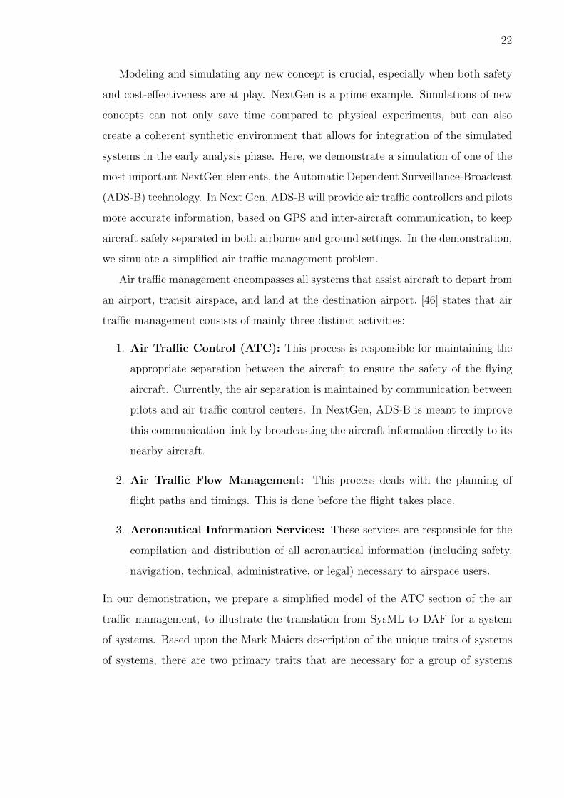
Modeling and simulating any new concept is crucial, especially when both safety
and cost-effectiveness are at play. NextGen is a prime example. Simulations of new
concepts can not only save time compared to physical experiments, but can also
create a coherent synthetic environment that allows for integration of the simulated
systems in the early analysis phase. Here, we demonstrate a simulation of one of the
most important NextGen elements, the Automatic Dependent Surveillance-Broadcast
(ADS-B) technology. In Next Gen, ADS-B will provide air traffic controllers and pilots
more accurate information, based on GPS and inter-aircraft communication, to keep
aircraft safely separated in both airborne and ground settings. In the demonstration,
we simulate a simplified air traffic management problem.
Air traffic management encompasses all systems that assist aircraft to depart from
an airport, transit airspace, and land at the destination airport. [46] states that air
traffic management consists of mainly three distinct activities:
1. Air Traffic Control (ATC): This process is responsible for maintaining the
appropriate separation between the aircraft to ensure the safety of the flying
aircraft. Currently, the air separation is maintained by communication between
pilots and air traffic control centers. In NextGen, ADS-B is meant to improve
this communication link by broadcasting the aircraft information directly to its
nearby aircraft.
2. Air Traffic Flow Management: This process deals with the planning of
flight paths and timings. This is done before the flight takes place.
3. Aeronautical Information Services: These services are responsible for the
compilation and distribution of all aeronautical information (including safety,
navigation, technical, administrative, or legal) necessary to airspace users.
In our demonstration, we prepare a simplified model of the ATC section of the air
traffic management, to illustrate the translation from SysML to DAF for a system
of systems. Based upon the Mark Maiers description of the unique traits of systems
of systems, there are two primary traits that are necessary for a group of systems

23
to be considered as a system of systems: operational independence and managerial
independence [47]. Operational independence implies that each system is capable
of performing a set of functions without any interactions from the other systems.
Managerial independence implies that the systems manage themselves to a purpose
separate from the ultimate purpose of the system of systems. For the Air Traffic
Control system, the aircraft can be considered as an operationally independent system
performing the task of travelling from an origin to a destination along with satisfying
the overarching goal of fulfilling the demand of the air transportation network.
Our model consists of a group of aircraft, equipped with ADS-B as the only com-
munication technology, approaching each other. ADS-B consists of two sub-systems:
ADS-B In (component responsible for receiving the other aircraft information) and
ADS-B Out (component responsible for transmitting the aircraft information). All
the aircraft are required to maintain a fixed minimum separation from other air-
craft to reduce the risk of aircraft collision, as well as prevent accidents due to wake
turbulence. Air traffic control enforces minimum separation rules to achieve this
(FAA order 7110.65). A defined loss of separation between airborne aircraft occurs
whenever the specified separation minima in the controlled airspace are breached.
In such cases, a system known as the Airborne Collision Avoidance System (ACAS)
comes into action to avoid collision. In simpler terms, if the separation bubbles of
two aircraft intersect at any time, both aircraft change direction as per the collision
avoidance algorithm. The ADS-B can broadcast and receive the aircraft information
within a fixed distance. Thus, the aircraft can see other aircraft only if it is within
the range of its ADS-B In. Fault is also introduced in the simulation by shutting off
the ADS-B In system of an aircraft by a pre-defined trigger. With a faulty ADS-B
In, the aircraft fails to see other aircraft in its ADS-B In range.
The Aircraft agent can divided in mainly two parts:
1. Subsystem containing all the communicating sensors and the auto-pilot system
responsible for driving the agent. To simplify the implementation, both the

24
communicating sensors and the auto-pilot system are considered under this
single section.
2. ACAS, the collision avoidance system which makes decisions regarding the
agent’s flight path based on the information about other agents and the sepa-
ration rules.
The working of Aircraft agent is defined in the Figure 2.7, which is consistent with
Figure 2.4 and is patterned after the activity diagram of a generic agent from [37]. The
ADS-B In receives the State Vector (position and heading direction) of the aircraft
that are within the range of the ADS-B In. Based on this input, the subsystem
updates the state vector database. This information is then transferred to the ACAS,
which decides upon the flight path based upon this information and the objective
to maintain a minimum distance from other aircraft. This updated path is now
sent to the subsystem as a command for the auto-pilot module. Simultaneously, the
communication module broadcasts the updated state vector of the aircraft using ADS-
B Out. In our demonstration, the logical network (Figure 2.8) consists of relevant
information going to and from aircraft agents. The physical network (Figure 2.9)
consists of the specific ADS-B In and ADS-B Out communication implementations.
For this example, after defining the block diagram of the aircraft agent, we create a
parametric diagram for the agents which utilizes the ParaMagic plugin and MATLAB
script to convert the parameters of each aircraft into agent files required for the
DAF simulation. Since all the agents in our simulation are of the same type, we
convert their specifications (i.e., initial positions and initial velocities) directly from
one parametric diagram. A screen-shot of the parametric diagram is shown in Figure
2.10.
The constraint block shown above uses the MATLAB script matlab aircraft to
generate the required DAF agent files. The parameters are input into this MATLAB
script and it gives the output flag a value (1, if file generation is successful and 0
otherwise). The DAF agent file is generated in the same folder as the MATLAB script.

25
Figure 2.7. Activity Diagram for Aircraft agent
Figure 2.8. Logical Network

26
Figure 2.9. Physical Network
Figure 2.10. Parametric diagram for DAF agent file generation

27
Figure 2.11. ParaMagic instance browser for agent file generation
Figure 2.11 shows Instance browser for one such run. Note that all the parameter
values are given, and the flag value is the target value of the run. The first two entries
of parameters represent the number of aircraft and number of specifications for each
aircraft respectively. The rest of the values represent initial position (x-component),
initial position (y-component), initial velocity (x-component) and initial velocity (y-
component) for each aircraft in that order.

28
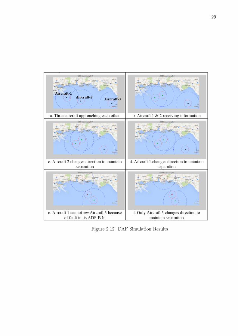
2.6 Results of the Simulation
After creating the SysML networks and establishing the connection between SysML
and DAF, the agent-based simulation was executed with a group of aircraft agents
working based on the established rules and objectives. The simulation snapshots are
tabulated in Figure 2.12.
The range of ADS-B In is denoted by the blue circle in the simulation. The
red circle denotes the critical separation zone for each aircraft. As soon as another
aircraft comes in the ADS-B In range, the aircraft receives the data (starts seeing the
aircraft) and turns green. When the separation bubbles of two aircraft intersect, both
aircraft change their path based on the collision avoidance algorithm to maintain the
minimum separation. Right now, a very simplified collision avoidance algorithm is
implemented where aircraft move in the direction perpendicular to the vector formed
between the two aircraft. The faulty aircraft is denoted by turning its marker red.
We can see in the simulation that the faulty aircraft does not change path because it
cannot see the other aircraft in its ADS-B In range.
Thus, we can see that a proper translation from SysML to an executable agent-
based simulation model can be achieved. But there are two major issues that remain
to be settled:
1. Scalability: The example problem is a very simplified version of a real-world
situation. We observed in the example with three same type of agents with
four specification parameters for each, the number of parameters needed for
each simulation is 14. A more comprehensive and detailed version could be
very large and complex, with a number of different agents involved and many
instances of each. The construction and organization of such a large simulation
is a major challenge of its own, but so may be the ability of this SysML-ABM
mapping approach.
2. Coarse-Graining: To achieve an efficient mapping, we should be able to first
identify and then extract all the relevant information from the SysML model to
29
Figure 2.12. DAF Simulation Results

30
create an executable agent-based simulation model. The identification, extrac-
tion and management of this information is a difficult task and depends heavily
on the knowledge about the internal functioning of both domain-specific tool-
boxes (of SysML and the agent-based simulation model). For example, in the
demonstration problem, we assume the network of aircraft agents to be fully
connected and thus, we were able to minimize the relevant information to the
initial state characteristics of each aircraft. In a real world complex system, our
network might not be fully connected and we will have to transfer this informa-
tion from SysML to agent-based modeling tool. This information can be really
difficult to extract and manage.
2.7 Lessons Learned
In this chapter, we showed how we can use a conceptual system representation in
SysML to get an executable agent-based simulation. We also identified major chal-
lenges in achieving this translation for a real-world system. We explained a generic
translation framework with the help of simple air traffic management problem. The
framework helped us automate the simulation process, to some extent, directly from
the SysML model. We were able to generate agent files required for the ADS-B sim-
ulation directly from the SysML element definition. The case study proves that this
translation can be achieved, but we still have major challenges including scalability
of the efficiency in the mapping process. While working on the translation, we also
realized that automating the analysis process for a model-based system definition
of complex real-world systems requires development of formal specifications for the
domain-specific toolboxes involved.

31
3. Tackling the Regulatory Issues
In this chapter, we discuss the model-based approach to the engineering design of
systems given by Buede [23]. We demonstrate the abstract nature of the approach by
applying it to a Healthcare design problem and see if we can capture the regulatory
requirements in the model-based representations.
3.1 Introduction to the Engineering Design of Systems
In his book, The Engineering Design of Systems [23], Buede describes the engi-
neering of a system as “the engineering discipline that develops, matches, and trades
off requirements, functions, and alternate system resources to achieve a cost-effective,
life-cycle-balanced product based upon the needs of the stakeholders”. He explains it
further using the famous “Vee” diagram (Fig. 3.1) where the design process starts
at the top left of the diagram with the definition of the operational needs of the
stakeholders. These needs are then further decomposed to generate system-level re-
quirements to eventually create specifications for each configurations item (CI). These
specifications are then used by the design (or discipline) engineers to design and pro-
duce the CIs. The right side of the “Vee” represents the integration of these CIs to
create the final system which is then verified and validated with the help of the quali-
fication system that is created based on the needs of the stakeholders identified in the
first step. The whole design process moves from left to right in time where iteration
between the high- and low-levels is not only important but highly encouraged. The
horizontal line depicts the point where information is handed-off from system engi-
neers to respective discipline engineers who will produce the physical entity satisfying
the given specifications. This line can be moved higher or lower to represent decreas-
ing or increasing overlap between design and integration activities. For example, if

32
Figure 3.1. Systems Engineering “Vee” Diagram [48]
the horizontal line is draw above the intersection of the “Vee”, it means that there
is no overlap between the design and integration activities. This could represent the
contractual relationship between procurers and suppliers in the design process.
Now, in the following case study, we demonstrate that this model-based approach
is not only capable of capturing the regulatory requirements but also identifies the
appropriate design stages related to these requirements.
3.2 Healthcare Case Study
Healthcare industry is one of the most safety-critical industries where product
designs are driven by different standards and regulations to a large extent. Therefore,
we chose to demonstrate how regulatory requirements are expressed using a model-
based representation of the design process of a healthcare device. This work has been
33
done in collaboration with the INCOSE Healthcare MBSE Challenge Team [49], who
are working with an aim to demonstrate the value of MBSE for biomedical-healthcare
devices. The challenge team provided the expertise regarding the healthcare side of
this case study.
3.2.1 Introduction
The challenge team has been working on creating a reference model for an in-
fusion pump. U.S. Food and Drug Administration (FDA) defines infusion pump as
“a medical device that delivers fluids, such as nutrients and medications, into patient
body in controlled amounts” [50]. For the last few years, the Laboratory of Software
Engineering at FDA has been working with various academic collaborators to develop
model-based tools and verification techniques for infusion pumps. FDA believes that
these model-based tools not only save costs and time but also make the design more
robust and efficient as problems can be identified and resolved at early phases of de-
sign [50] [51] [52]. In our work, we adapted the model-based process representations
described by Buede [23] in SysML diagrams to represent the system life cycle pro-
cesses of an infusion pump. Moreover, we harmonized these representations with the
following three standards:
1. ISO 15288: Systems and software engineering - System life cycle processes [53]
2. ISO 14971: Application of Risk Management to Medical Devices [54]
3. IEC 62366-1: Application of Usability Engineering to Medical Devices [55]
3.2.2 Process Diagrams
The system life-cycle process is represented with the help of SysML block defini-
tion, internal block and activity diagrams. All the diagrams are connected using a
navigation page as shown in Figure 3.2. The diagrams on the navigation page are
categorized into following three categories:

34
1. Pre-Systems Engineering Processes: The diagrams in this region repre-
sents the steps that occur before the start of the system-level design activities.
This could be considered as the highest level of abstraction of the design process.
2. System-level Design Activities: The region marked in green contains dia-
grams for all the processes involved in the system-level design activities from
problem definition to qualification system development.
3. Mapping Information: The process diagrams in the above categories are
mapped to the sections and terminologies of ISO 14971:2007 [54]. This mapping
works like a dictionary between SE and Healthcare terminology.
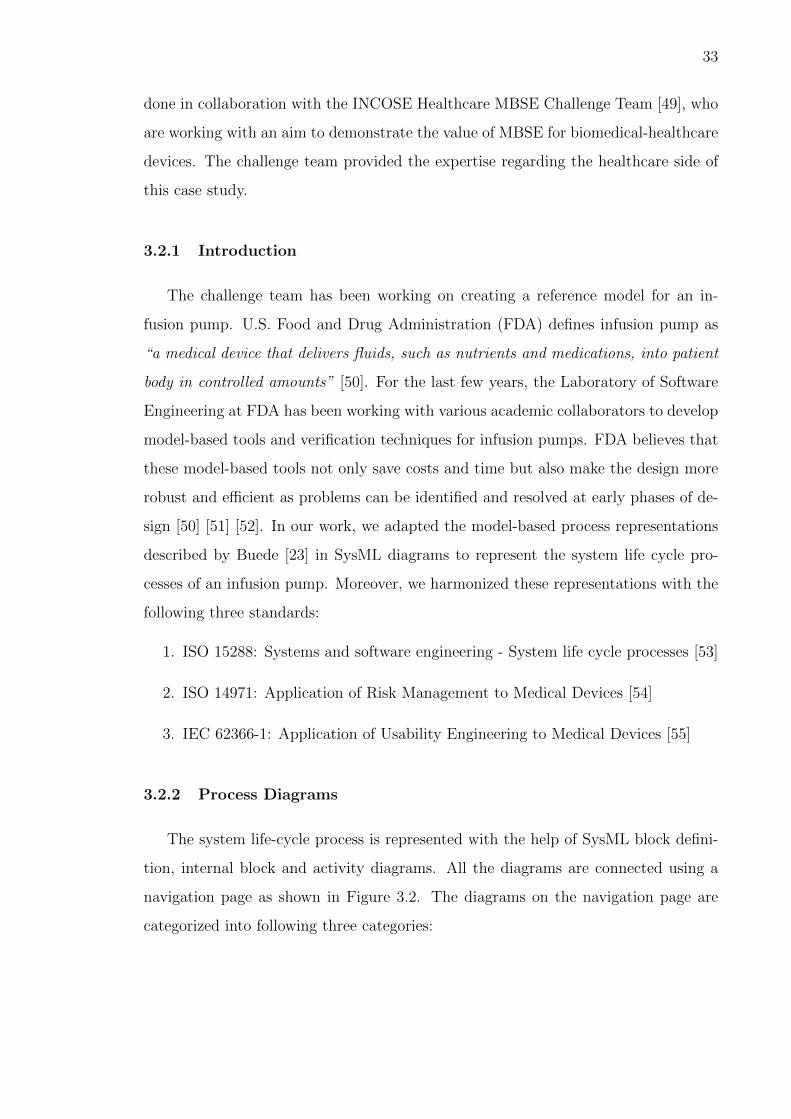
Examples from the Diagrams
A lot of process diagrams were generated to represent the design process. We
discuss some of the process diagrams here but all the generated diagrams are com-
piled in the Appendix A. In the block definition diagram shown in Figure 3.3, we see
all the activities (or steps) that are part of the Development Phases (highest-level of
abstraction). The activity representing systems engineering is marked as our system-
of-interest. The information flow diagram for these development phases (figure 3.4)
shows the information flow across these steps. The information flow diagram consists
of swimlanes that distribute the steps among different groups, namely, the stake-
holders, the SE team, the discipline engineers and the qualification system discipline
engineers, in the team. It should be noted that for a small design team, the same
person can play more than one role in this diagram. Figure 3.5 provides an zoomed-in
view of the inputs and outputs of the SE activity.

35
Figure 3.2. The Navigation Page

36
Figure 3.3. Development Phases - Block Definition Diagram

37
Fig
ure
3.4.
Info
rmat
ion
flow
acro
ssdiff
eren
tD
evel
opm
ent
Phas
es
38
Figure 3.5. Perform Systems Engineering
Another example from the process diagrams is shown in Figure 3.6, where steps for
Allocated Architecture Development, a system-level design activity, are represented.
Some of these steps are further broken down in attributes that are mapped from ISO
14971 using the approach followed by Malins et al. [56]. Similarly, in the activity flow
diagram (Figure 3.7), the specific section from IEC 62366-1 is mapped to relevant
step using comments.

39
Figure 3.6. Allocated Architecture Development - Block Definition Diagram

40
Fig
ure
3.7.
Act
ivit
yF
low
Dia
gram
for
Alloca
ted
Arc
hit
ectu
reD
evel
opm
ent

41
Figure 3.8. Mapping Buede’s diagrams with ISO 14971
Finally, figure 3.8 summarizes the mapping of ISO 14971 to different activities
in the model-based process representations. This kind of mapping table not only
serves as a Rosetta Stone between system engineers and other domain experts (here,
Healthcare) but also traces the regulatory requirements to specific design steps making
the design process more efficient and robust.

42
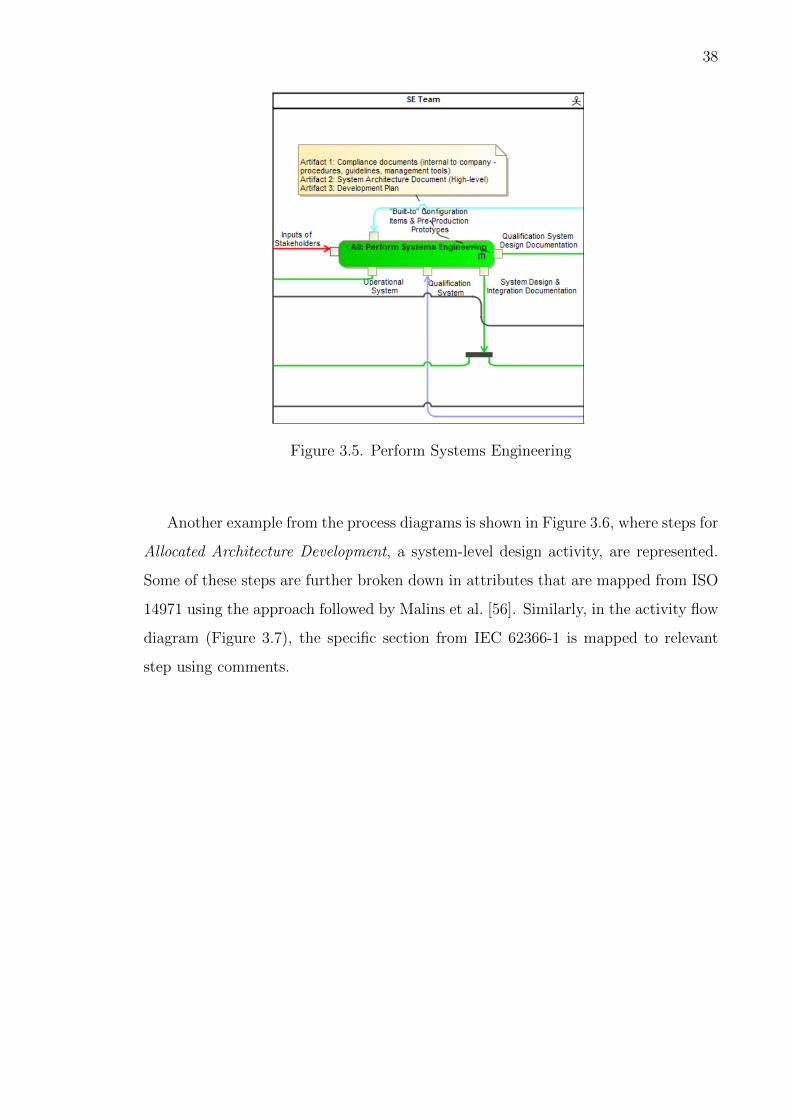
3.3 Lessons Learned
In this chapter, we adapted the model-based process representations, given by
Buede, to represent the product design process of a biomedical device. We observed
that the model-based approach not only manages to capture the regulatory require-
ments but also map them to specific design activities. The identification of the stages
where a standard is being used makes the design process more efficient and robust
from the perspective of compliance activities. The method of creating the mapping
tables also serves as a means to communicate the SE knowledge to other domains.

43
4. UAV Design Case Study
In this chapter, we apply the product design approach explained in the chapter 3 to
an unmanned aerial vehicle (UAV) design process. We will also adapt the translation
framework, developed in the chapter 2, to connect the model-based representations
with another analysis tool, XFOIL [57].
4.1 Introduction
The US Department of Defense defines UAV as “a powered, aerial vehicle that
does not carry a human operator, uses aerodynamic forces to provide vehicle lift,
can fly autonomously or be piloted remotely, can be expendable or recoverable, and
can carry a lethal or nonlethal payload” [58]. Today, the UAVs are used for both
military and non-military purposes including search and rescue operations, forest fire
detections, acrobatic aerial footage in film-making and leisure flying. Consider the
design process of one such UAV, which is planned to be used as the first responder
during emergency conditions. The UAV is supposed to gather information about the
emergency site until emergency personnel arrives on scene.
4.2 System-level Design Activities
Now, we follow the SE process, shown as the system-level design activities in the
chapter 3, to design the UAV.
4.2.1 Problem Definition
Based on the figure 3.2, the first step in the design process to define the problem.
After identifying the need, it is important to capture the important requirements as

44
Figure 4.1. Mission Scenario
these requirements will work as the foundation for the whole design process. It is
also important to have solution neutral requirements to avoid introducing artificial
limitations. In our case, the mission of the UAV can be defined as: “To design a
rapid deployable UAV first responder to the scene of an emergency while Police, Fire,
and Medical teams are en route”. A mission scenario, which has been defined by the
stakeholders in the pre-SE processes, is shown in the Fig. 4.1. Based on the given
information, the most important requirements for this UAV can be depicted in the
model-based representations, as shown in Fig. 4.2.
4.2.2 Functional Decomposition
The next step after properly defining the problem is to decompose the system
into different components (or subsystems) based on their functions. It is advisable to
name the components, based on their functions, rather than the physical component
associated with it. For example, instead of propellers, the component is named as
thrust system. This method of classifying and naming components not only keeps the
process solution neutral but also makes it easy to determine the impact of changing

45
Figure 4.2. Model-based Representation of the Requirements

46
Figure 4.3. Functional Decomposition of the UAV system
the physical component through the model traceability. An example of functional
decomposition for our system is shown in Fig. 4.3.
4.2.3 Physical Architecture Design
Once the functional decomposition is completed to enough detail, the develop-
ment of the physical concepts that will satisfy the given functions start. Now, the
design of these physical concepts can be a very complex process involving further
decomposition and this is where the horizontal line in the “Vee” diagram (Fig. 3.1 is
drawn. For example, in our system, the Lift System can have either Wing or Rotors
or a combination of both as possible physical concepts. Moreover, as shown in the
Fig. 4.4, the Wing can be further broken down into different types: Fixed Wing and
Folding Wing. Our final concept design will consist of any one (or a combination) of
these physical concepts.
4.2.4 Architecture Allocation
Once a number of physical concepts are generated, the next step is to analyze
and allocate the most suitable architecture, based on the performance metrics. The
detailed steps for this activity are shown in the Fig. 3.6. For example, in our case, the
best Fixed Wing can be selected based on its Airfoil and Structural characteristics

47
Figure 4.4. Physical Architecture for the Lift System

48
Figure 4.5. Decomposition of Physical Design of a Fixed Wing
(Figure 4.5). We will see how the analysis tool (XFOIL) is connected to the airfoil
analysis in the next section.
4.2.5 Interface Architecture Development
After allocating the physical concepts based on the functional decomposition, we
develop the architecture for the interaction between the components. This step is

49
crucial to identify the critical components in the design and make sure that the
allocated physical components are compatible with each other. For example, in our
design, at this step, the interface between the thrust system and lift system will be
developed, i.e., we will understand the interaction between the propellers and the
fixed wing.
4.2.6 Qualification System Development
The final step in the design process is to verify that the designed system satisfies
the requirements created in the beginning. In this step, we develop the qualification
system that will perform this check on the final design. For example, for the UAV
design, we might have to perform a timed test flight to show if our final design can
fly for 40 minutes.
4.3 Airfoil Analysis using XFOIL
In this section, we will explain how we can modify the translation framework,
explained in the chapter 2, to connect model-based representations with any analy-
sis tool. We demonstrate the modified framework by enabling the translation from
model-based representations to XFOIL, a low-fidelity aerodynamic analysis tool.
In chapter 2, one of the challenges with the translation framework (Fig. 2.5) is
that every pair of domain specific toolboxes require a different translator. Due to
this shortcoming, even though the framework provides a guideline towards solving
the challenge of connecting the MBSE representations with analysis tools, its proper
implementation is still a daunting task. To address this challenge, we propose a slight
modification to the framework (see Fig. 4.6). We observed that due to the popularity
of computational tools like MATLAB R©, Python, etc., a number of important analysis
tools are already interfaced with these tools [59]. In fact, The MathWorks Inc. has
been releasing comprehensive documentation on how to interface external tools with
MATLAB R© [60]. So, if we can enable the translation of MBSE representations to

50
Figure 4.6. Modified Translation Framework
these popular computational tools (intermediate tool), we will be able to enable the
translation to a number of analysis tools (specific tool). We demonstrate the modified
translation framework in the following section.
4.3.1 Demonstration
During Architecture Allocation (section 4.2.4), Conduct Performance and Risk
Analyses is one of the most important step as the results of this analysis will determine
which concept will be selected for the final design. For example, in the UAV example,
the design process of a Fixed Wing can be further divided into Airfoil Design and
Structural Design (Fig. 4.5. Now, we perform the airfoil analysis using XFOIL.
Say, we want to perform an aerodynamic analysis of NACA 24012 airfoil for our
UAV. The analysis can be done in the following three steps:

51
Figure 4.7. Snippet from the generated MATLAB file
1. We transfer the information about the airfoil geometry (standard NACA 5-digit
series number here) to MATLAB with the help of the translator developed in
the chapter 2. Figure 4.7 shows a snippet of the generated MATLAB file after
the translation.
2. Next, we use the MATLAB-XFOIL interface developed by Rafael Oliveira to
perform the aerodynamic analysis [61]. Figure 4.8 shows a snapshot of the
XFOIL analysis.
3. Figure 4.9 shows the generated results for various aerodynamic parameters. We
can select and feedback values to the MBSE model as per our requirements.

52
Figure 4.8. Snapshot of the XFOIL Analysis

53
Fig
ure
4.9.
Fin
alX
FO
ILA
nal
ysi
sR
esult
s
54
4.4 Lessons Learned
In this chapter, we showed how the Buede’s process representation diagrams that
were used to represent the product design process of a biomedical device can be used
to describe the design process of a UAV. With the help of UAV case study, we also
demonstrated how the translation framework that was introduced in the Chapter 2
can be adapted to implement it to other analysis tools. The third step of translation
from the conceptual model to the simulation model was broken into two steps, where,
first the conceptual model is translated to an intermediate popular tool and then the
existing interface between the intermediate and the analysis tool is used to translate
to the simulation model. This additional step makes the translation to the analysis
tool more efficient.

55
5. Conclusions and Future Work
5.1 Conclusions
This thesis outlines the advantages of MBSE and identifies the major roadblocks in
its industrial adoption. With the help of three case studies, the author has suggested
ways to handle two of these challenges. Although the answers to the research questions
have been explained in detail throughout the document, we summarize them here:
• What are the features of an effective framework for translating model-based con-
ceptual representations to analysis models?
In Chapter 2, the author proposes a translation framework that enables the
translation from a SysML conceptual model (created using MagicDraw) to an
executable agent-based simulation model. The translation framework was also
demonstrated using a simplified air transportation problem where three aircraft,
communicating only using ADS-B, had to maintain a minimum separation dis-
tance. Along with the demonstration, a number of challenges were also iden-
tified that might hinder the implementation of the framework to a real world
complex problem. In Chapter 4, the author proposes a modification to the
framework to address one of the identified challenges. The modified framework
was demonstrated using an airfoil analysis problem.
• What are the specific products in a typical model based representation that, when
properly formed, could be used to satisfy the regulatory requirements? And do
these model based representations provide any benefit over the document-based
approach?
In Chapter 3, Buede’s systems engineering diagrams were adapted to represent
the product design process of a biomedical device. Three standards, namely,

56
ISO 15288, ISO 14971 & IEC 62366-1, were also harmonized with the represen-
tations to demonstrate that the model-based representations not only capture
the regulatory requirements but also show the stages (in product lifecycle) where
a specific standard will be used. Thus, it makes the design process more efficient
and robust with respect to the regulations.
Overall, it was shown that the MBSE representations are capable of capturing
the processes involved during the product lifecycle efficiently. Moreover, a translation
framework was proposed to move towards the integration of MBSE with PLM.
5.2 Future Work
In this work, in addition to identifying and demonstrating strategies towards in-
dustrial adoption of MBSE, we also identified the challenges associated with it. Es-
tablishing the link between the model-based design representations and the analysis
tools is crucial for the integration of MBSE & PLM and this work just describes the
initial steps. Some of the future directions, categorized as short-term and long-term,
are described in the following subsections:
5.2.1 Short-term
1. Scalable Translation: At the current stage, the translation to an agent-
based simulation model works fine when the model-based representation does
not contain a large number of occurrences of the same (or similar) element(s).
But since design reuse is one of the main advantages of MBSE, it is really
important to make the translation framework scalable for multiple occurrences
of the same element.
2. Coarse Graining: As the same model-based representation can be connected
to a number of analysis tools to perform different design evaluations, it is critical
to be able to identify and extract the “relevant” information from the repre-

57
sentation. With an increase in the complexity of the systems, it is essential to
manage models to retain the important information and in doing that, discov-
ering what is important is the biggest challenge. To tackle this challenge, un-
derstanding the development of the Computer-Aided Engineering (CAE) tools,
where information is extracted from CAD models to perform different engineer-
ing analyses, can be a good place to start.
3. Interface Standards: There is a need to standardize the information exchange
between different analysis tools. These standards can boost the usefulness and
interoperability of the tools. For example, the development of ISO 10303, in-
formally known as STEP, has worked wonders for the CAD industry.
4. Impact on Cognitive Load: Another interesting area is to explore the impact
of MBSE on the cognitive load of the design engineers. The richer and high-
fidelity representations should not only make the design process more efficient
but should also make it easier for the interdisciplinary teams of design engineers
to interact and understand each other.
5. Link with the Downstream Phases: In our work, we mainly talk about
the link between the model-based design representations and the analysis tools
but we also need to establish the links with the downstream phases, such as
manufacturing, product sustainability, etc., as well to make the model-based
approach more relevant to the design process.
5.2.2 Long-term
1. Dissemination of SE knowledge: The difference in the vernacular termi-
nology is the biggest hurdle in the application of SE to different domains. As
described using the mapping table (Figure 3.8) in the Chapter 3, we mapped
the information from SE to the corresponding Healthcare terminology. Creating

58
similar lexicons, with the help of domain experts and systems engineers, is vital
to handle the increasingly interdisciplinary nature of the products.
2. MBSE-PLM Integration: To realize the maximum benefit from the model-
based approach, it is very important to integrate the MBSE with the PLM.
Currently, all the PLM tools are mainly managing the various documents (for
example, spreadsheets, checklists, etc.) used throughout the lifecycle of the
product. The next generation PLM tools must itself be model-based by incor-
porating more structured information with meaning and should follow a stronger
model-based approach than they do today. The MBSE-PLM integration will
not only boost the adoption of MBSE in the industry and but will also make
the PLM tools more functional and thus, will lead us to a more efficient design
process of the future.

REFERENCES
59
REFERENCES
[1] Ludwig Von Bertalanffy. An outline of general system theory. British Journalfor the Philosophy of Science, 1950.
[2] A Wayne Wymore. Model-based systems engineering: An introduction to themathematical theory of discrete systems and to the tricotyledon theory of systemdesign, vol. 3, 1993.
[3] Charles Keating, Ralph Rogers, Resit Unal, David Dryer, Andres Sousa-Poza,Robert Safford, William Peterson, and Ghaith Rabadi. System of systems engi-neering. Engineering Management Journal, 15(3):36–45, 2003.
[4] INCOSE. What is Systems Engineering, 2015 (accessed October 26, 2015).
[5] JH Williams. National airspace system: System engineering manual. FederalAviation Administration ATO Operations Planning, 2006.
[6] Stephen J Kapurch. NASA Systems Engineering Handbook. DIANE Publishing,2010.
[7] Lawrence R Guinta and Nancy C Praizler. The QFD book: The team approach tosolving problems and satisfying customers through quality function deployment.Amacom, 1993.
[8] Yoji Akao. Quality function deployment. 2004.
[9] M Hamilton. Inside development before the fact. Electronic Design, April, 4,1994.
[10] INCOSE. Systems engineering vision 2020 (incose-tp-2004-004-02). INCOSE,2007.
[11] Fran Thom. Realizing the benefits of mbse: Improving multi-discipline teamcommunication, 2015.
[12] Sanford Friedenthal, Alan Moore, and Rick Steiner. A practical guide to SysML:the systems modeling language. Morgan Kaufmann, 2014.
[13] Julian Johnson, Jean-Louis Loeuillet, Manfred Inderst, Benny Nilsson, AndersTorne, Linda Candy, David Harris, and Federica Luise Alenia. 3 the futuresystems engineering data exchange standard step ap-233: Sharing the resultsof the sedres project. In INCOSE International Symposium, volume 9, pages764–772. Wiley Online Library, 1999.
[14] ECSS (European Cooperation for Space Standardization). Ecss-e-tm-10-23aspace engineering - space system data repository. 2011.

60
[15] Klaus Pohl, Gunter Bockle, and Frank J van der Linden. Software product lineengineering: foundations, principles and techniques. Springer Science & BusinessMedia, 2005.
[16] ISO ISO. 26550: 2015. Software and systems engineering - Reference model forproduct line engineering and management, 2015.
[17] NoMagic. Modeling Community Blog, 2015 (accessed November 9, 2015).
[18] NoMagic. Sparx, 2015 (accessed November 9, 2015).
[19] Jeff A Estefan et al. Survey of model-based systems engineering (mbse) method-ologies. Incose MBSE Focus Group, 25:8, 2007.
[20] Dave Nichols. The application of mbse at jpl through the life cycle. INCOSEWorkshop, 2014.
[21] Russell Peak, Leon McGinnis, and Chris Paredis. Academia as an educator inthe world of mbse. INSIGHT, 18(2):30–34, 2015.
[22] Model-based systems engineering center, 2015 (accessed November 20, 2015).
[23] Dennis M Buede. The engineering design of systems: models and methods, vol-ume 55. John Wiley & Sons, 2011.
[24] Brian London. A model-based systems engineering framework for concept devel-opment. PhD thesis, Massachusetts Institute of Technology, 2012.
[25] Barbara Sheeley. Mbse implementations across diverse domains at the boeingcompany. INCOSE Workshop, 2014.
[26] Eric Berg. Affordable systems engineering: An application of model-based systempatterns to consumer packaged goods products, manufacturing, and distribution.INCOSE Workshop, 2014.
[27] Mary Bone and Robert Cloutier. The current state of model based systems engi-neering: Results from the omg sysml request for information 2009. In Proceedingsof the 8th Conference on Systems Engineering Research, 2010.
[28] Robert Cloutier. Mbse survey 2. INCOSE Workshop, 2012.
[29] J. Tower. Model based systems engineering ’the state of the nation’. In INCOSEUK Annual Systems Engineering Conference (ASEC), UK-Oxfordshire, 2013.
[30] Robert Cloutier. Current modeling trends in systems engineering. INSIGHT,18(2):10–13, 2015.
[31] Harald Eisenmann. Mbse has a good start; requires more work for sufficientsupport of systems engineering activities through models. INSIGHT, 18(2):14–18, 2015.
[32] David Long. Beyond mbse: Looking towards the next evolution in systemsengineering. Keynote presentation at the 9th Great Lakes Regional Conference,Cleveland, Ohio, 2015.

61
[33] Roy S Kalawsky. Grand challenges for systems engineering research. In Pro-ceedings of the 7Th Annual Conference on Systems Engineering Research, pages20–23, 2009.
[34] Jerry Krasner. How Development Organizations can Achieve Long-Term CostSavings Using Product Line Engineering (PLE), March 2014.
[35] 10 theses about mbse and plm, July 2015 (accessed December 5, 2015).
[36] Hartman Nathan. Purdue Product Lifecycle Management Center - Overview &Opportunities, 2015 (accessed November 9, 2015).
[37] C Robert Kenley, Timothy M Dannenhoffer, Paul C Wood, and Daniel A De-Laurentis. Synthesizing and specifying architectures for system of systems. 2014.
[38] Daniel DeLaurentis. Understanding transportation as a system-of-systems designproblem. In 43rd AIAA Aerospace Sciences Meeting and Exhibit, volume 1. AIAAReno, NV. New York, 2005.
[39] Cliff Joslyn and Luis Rocha. Towards semiotic agent-based models of socio-technical organizations. In Proc. AI, Simulation and Planning in High AutonomySystems (AIS 2000) Conference, Tucson, Arizona, pages 70–79, 2000.
[40] Zhenghui Sha, Qize Le, and Jitesh H Panchal. Using sysml for conceptual rep-resentation of agent-based models. In ASME 2011 International Design Engi-neering Technical Conferences and Computers and Information in EngineeringConference, pages 39–50. American Society of Mechanical Engineers, 2011.
[41] Leon McGinnis and Volkan Ustun. A simple example of sysml-driven simulation.In Simulation Conference (WSC), Proceedings of the 2009 Winter, pages 1703–1710. IEEE, 2009.
[42] Oliver Schonherr and Oliver Rose. A general model description for discreteprocesses. In Simulation Conference (WSC), Proceedings of the 2011 Winter,pages 2201–2213. IEEE, 2011.
[43] Opt H Broodney, Dolev Dotan, Lev Greenberg, and Michael Masin. Genericapproach to architecture optimization in mbse. In INCOSE International Sym-posium, 2012.
[44] Matthew Liotine. Mission-critical network planning. Artech House, 2003.
[45] Ankur Mour, C Robert Kenley, Navindran Davendralingam, and Daniel De-Laurentis. Agent-based modeling for systems of systems. In 23nd Annual In-ternational Symposium of the International Council of Systems Engineering, atPhiladelphia, US-PA, 2013.
[46] Eurocontrol - Driving excellence in ATM performance, 2015 (accessed November9, 2015).
[47] Mark W Maier. Architecting principles for systems-of-systems. In INCOSEInternational Symposium, volume 6, pages 565–573. Wiley Online Library, 1996.
[48] Kevin Forsberg and Harold Mooz. The relationship of systems engineering tothe project cycle. Engineering Management Journal, 4(3):36–43, 1992.

62
[49] Biomedical-healthcare mbse challenge team: Modeling for a healthy future, 2015(accessed November 19, 2015).
[50] U.s. food and drug administration, 2015 (accessed November 19, 2015).
[51] David E Arney, Raoul Jetley, Paul Jones, Insup Lee, Arnab Ray, Oleg Sokolsky,and Yi Zhang. Generic infusion pump hazard analysis and safety requirementsversion 1.0. Technical Reports (CIS), page 893, 2009.
[52] Anaheed Ayoub, BaekGyu Kim, Insup Lee, and Oleg Sokolsky. A safety casepattern for model-based development approach. In NASA Formal Methods, pages141–146. Springer, 2012.
[53] Iso/iec/ieee international standard - systems and software engineering – systemlife cycle processes. ISO/IEC/IEEE 15288 First edition 2015-05-15, pages 1–118,May 2015.
[54] ISO ISO. 14971: 2007. Medical Devices Application of Risk Management toMedical Devices, 2007.
[55] Medical devices – part 1: Application of usability engineering to medical devices.IEC 62366-1, February 2015.
[56] Robert J Malins, Jack Stein, Ajay Thukral, and Christophe Waterplas. Sysmlactivity models for applying iso 14971 medical device risk and safety managementacross the system lifecycle. In INCOSE International Symposium, volume 25,pages 489–507. Wiley Online Library, 2015.
[57] Mark Drela. Xfoil subsonic airfoil development system, 2015 (accessed November23, 2015).
[58] US Department of Defense. Dictionary of Military and Associated Terms. 2005.
[59] Windows gui automation with python - pywinauto, 2015 (accessed November 24,2015).
[60] Matlab R© external interfaces, 2015 (accessed November 24, 2015).
[61] Xfoil - matlab interface, 2015 (accessed November 24, 2015).
[62] Alberto Sangiovanni-Vincentelli. Quo vadis, sld? reasoning about the trends andchallenges of system level design. Proceedings of the IEEE, 95(3):467–506, 2007.
[63] Brian Bailey, Grant Martin, and Thomas Anderson. Taxonomies for the Devel-opment and Verification of digital systems. Springer Science & Business Media,2005.

APPENDICES

63
A. SysML diagrams for the Healthcare Case Study
Figure A.1. Main Navigation Page

64
Figure A.2. Block Definition Diagram of the Development Phases

65
Fig
ure
A.3
.In
form
atio
nF
low
Acr
oss
the
Dev
elop
men
tP
has
es

66
Figure A.4. Perform Systems Engineering - Block Definition Diagram
Figure A.5. System-level Design Activities - Block Definition Diagram

67
Fig
ure
A.6
.In
form
atio
nF
low
Acr
oss
Syst
em-l
evel
Des
ign
Act
ivit
ies

68
Figure A.7. Problem Definition - Block Definition Diagram

69
Fig
ure
A.8
.In
form
atio
nF
low
Duri
ng
Pro
ble
mD
efinit
ion
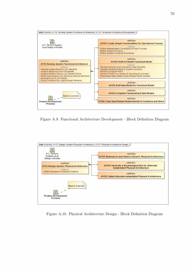
70
Figure A.9. Functional Architecture Development - Block Definition Diagram
Figure A.10. Physical Architecture Design - Block Definition Diagram

71
Figure A.11. Allocated Architecture Development - Block Definition Diagram

72
Fig
ure
A.1
2.In
form
atio
nF
low
Duri
ng
Arc
hit
ectu
reA
lloca
tion
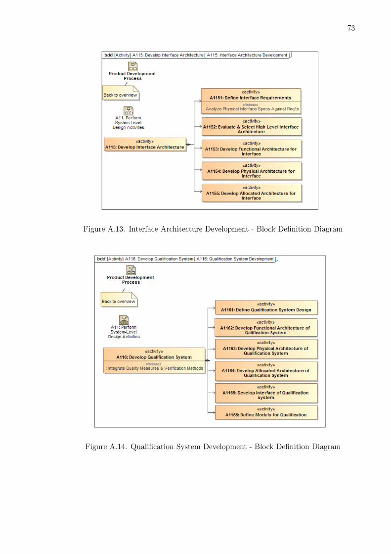
73
Figure A.13. Interface Architecture Development - Block Definition Diagram
Figure A.14. Qualification System Development - Block Definition Diagram
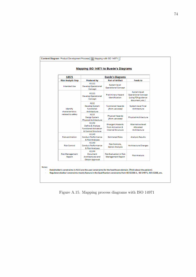
74
Figure A.15. Mapping process diagrams with ISO 14971

75
B. Traditional Top-Down Systems Engineering (TTDSE) and
Platform-Based Design (PBD)
The “Vee” diagram is also referred to as the Traditional, Top-Down Systems En-
gineering (TTDSE) Approach where we start at the top with the high-level system
definition and break it down until we reach the specifications of the CI which are
designed by the discipline engineers. In this section, we contrast this top-down ap-
proach with another design methodology, platform-based design (PBD), which was
proposed by Sangiovanni-Vincentelli [62].
PBD is defined as “an integration oriented design approach emphasising systematic
reuse, for developing complex products based upon platforms and compatible hardware
and software virtual component, intended to reduce development risks, costs and time
to market” [63]. This approach has its roots in the semiconductor and electronic
design automation industry but [62] argues that due to its abstract nature, it is
applicable to different industries including automotive, communication, computing,
Figure B.1. PBD Process [62]

76
avionics, building automation, space, agriculture, health and security. The basic
principle of PBD is to start the design process at the highest level of abstraction and
break-down the implementation to a certain functionality level where it is mapped
with a platform instance from the platform (or architectural) space. This mapping
is then carried out at number of times at different levels of abstractions to go from
the initial specification to the final implementation. The PBD process (as shown in
Figure B.1) can be seen as a meet-in-the-middle process contrary to the traditional
top-down (or bottom-up) approaches.

VITA

77
VITA
Apoorv Maheshwari is a Graduate Research Assistant in Purdue’s School of Aero-
nautics and Astronautics and School of Industrial Engineering in West Lafayette, IN
(US). He graduated from the Indian Institute of Technology, Mumbai (India) where
he completed his Bachelors in Aerospace Engineering. He is currently a member of the
Purdue System-of-Systems Laboratory and Product Lifecycle Management Center.
His primary research interests are in the areas of applying model-based systems engi-
neering to product lifecycle management, agent-based modeling, network theory, and
the application of random-utility discrete-choice theory to air transportation system.