inductors and capacitors - university of waterloone344/ne_week2_review1.pdf · 1 inductors and...
TRANSCRIPT

1
Inductors and Capacitors • Inductor is a Coil of wire wrapped around a supporting (mag or non mag) core
• Inductor behavior related to magnetic field
• Current (movement of charge) is source of the magnetic field
• Time varying current sets up a time varying magnetic field
• Time varying magnetic field induces a voltage in any conductor linked by the field
• Inductance relates the induced voltage to the current
• Capacitor is two conductors separated by a dielectric insulator
• Capacitor behavior related to electric field
• Separation of charge (or voltage) is the source of the electric field
• Time varying voltage sets up a time varying electric field
• Time varying electric field generates a displacement current in the space of field
• Capacitance relates the displacement current to the voltage
• Displacement current is equal to the conduction current at the terminals of capacitor

2
Inductors and Capacitors (contd)
• Both inductors and capacitors can store energy (since both magnetic fields and electric fields can store energy)
• Ex, energy stored in an inductor is released to fire a spark plug
• Ex, Energy stored in a capacitor is released to fire a flash bulb
• L and C are passive elements since they do not generate energy

3
Inductor
• Inductance symbol L and measured in Henrys (H)
• Coil is a reminder that inductance is due to conductor linking a magnetic field
• First, if current is constant, v = 0
• Thus inductor behaves as a short with dc current
• Next, current cannot change instantaneously in L i.e. current cannot change by a finite amount in 0 time since an infinite (i.e. impossible) voltage is required
• In practice, when a switch on an inductive circuit is opened, current will continue to flow in air across the switch (arcing)

4
Inductor: Voltage behavior
• Why does the inductor voltage change sign even though the current is positive? (slope)
• Can the voltage across an inductor change instantaneously? (yes)
5
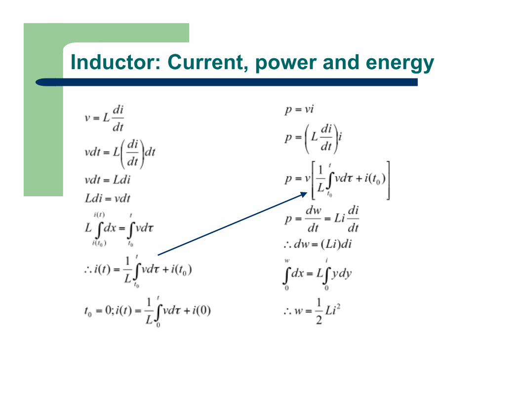
Inductor: Current, power and energy

6
Inductor: Current behavior
• Why does the current approach a constant value (2A here) even though the voltage across the L is being reduced? (lossless element)

7
Inductor: Example 6.3, I source
• In this example, the excitation comes from a current source
• Initially increasing current up to 0.2s is storing energy in the inductor, decreasing current after 0.2 s is extracting energy from the inductor
• Note the positive and negative areas under the power curve are equal. When power is positive, energy is stored in L. When power is negative, energy is extracted from L

8
Inductor: Example 6.3, V source
• In this example, the excitation comes from a voltage source
• Application of positive voltage pulse stores energy in inductor
• Ideal inductor cannot dissipate energy – thus a sustained current is left in the circuit even after the voltage goes to zero (lossless inductor)
• In this case energy is never extracted

9
Capacitor • Capacitance symbol C and measured in Farads (F)
• Air gap in symbol is a reminder that capacitance occurs whenever conductors are separated by a dielectric
• Although putting a V across a capacitor cannot move electric charge through the dielectric, it can displace a charge within the dielectric displacement current proportional to v(t)
• At the terminals, displacement current is similar to conduction current
• As per above eqn, voltage cannot change instantaneously across the terminals of a capacitor i.e. voltage cannot change by a finite amount in 0 time since an infinite (i.e. impossible) current would be produced
• Next, for DC voltage, capacitor current is 0 since conduction cannot happen through a dielectric (need a time varying voltage v(t) to create a displacement current). Thus, a capacitor is open circuit for DC voltages.
10
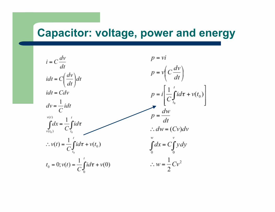
Capacitor: voltage, power and energy

11
Capacitor: Example 6.4, V source
• In this example, the excitation comes from a voltage source
• Energy is being stored in the capacitor whenever the power is positive and delivered when the power is negative
• Voltage applied to capacitor returns to zero with increasing time. Thus, energy stored initially (up to 1 s) is returned over time as well
12
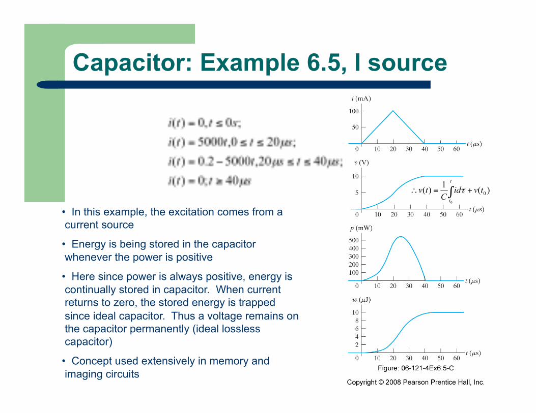
Capacitor: Example 6.5, I source
• In this example, the excitation comes from a current source
• Energy is being stored in the capacitor whenever the power is positive
• Here since power is always positive, energy is continually stored in capacitor. When current returns to zero, the stored energy is trapped since ideal capacitor. Thus a voltage remains on the capacitor permanently (ideal lossless capacitor)
• Concept used extensively in memory and imaging circuits
13
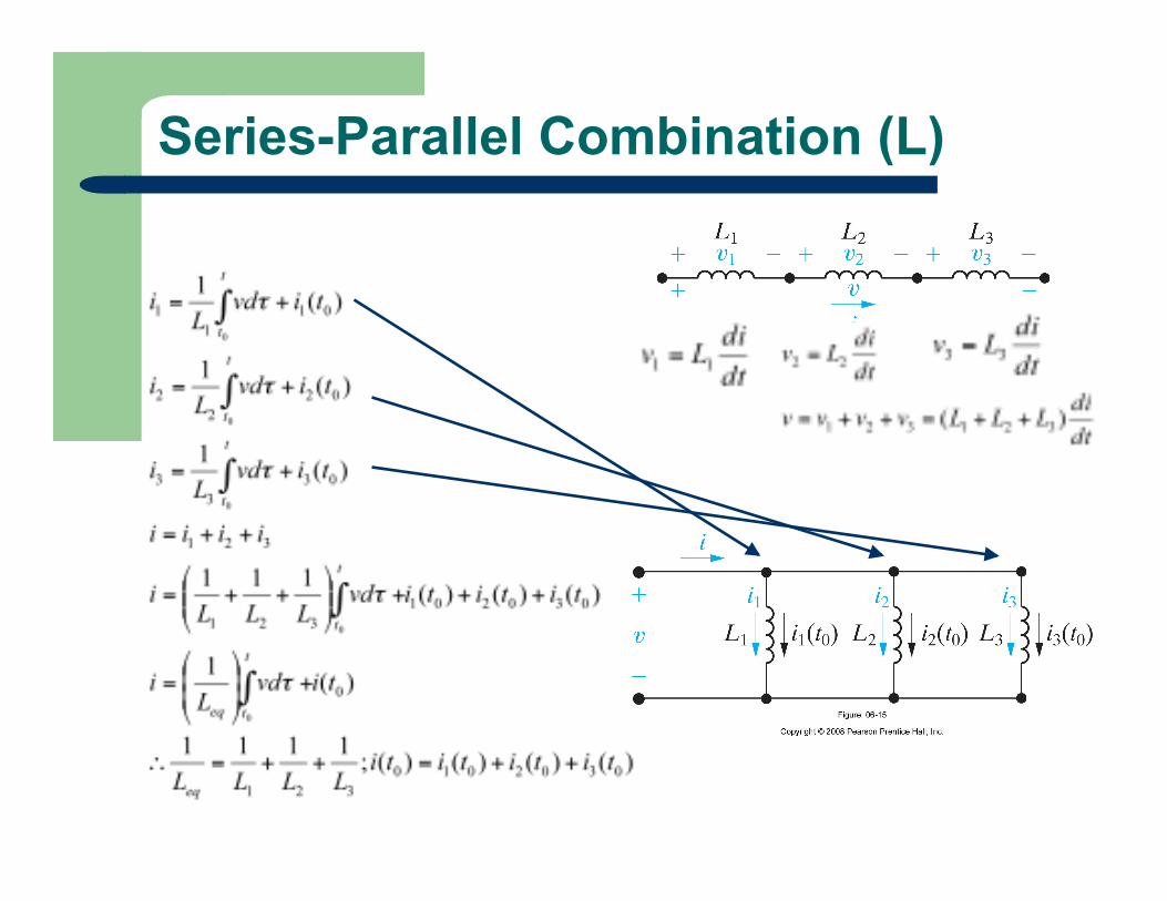
Series-Parallel Combination (L)

14
Series Combination (C)

15
Parallel Combination (C)

16
First Order RL and RC circuits • Class of circuits that are analyzed using first order ordinary differential equations
• To determine circuit behavior when energy is released or acquired by L and C due to an abrupt change in dc voltage or current.
• Natural response: i(t) and v(t) when energy is released into a resistive network (i.e. when L or C is disconnected from its DC source)
• Step response: i(t) and v(t) when energy is acquired by L or C (due to the sudden application of a DC i or v)

17
Natural response: RL circuit
• Assume all currents and voltages in circuit have reached steady state (constant, dc) values
Prior to switch opening,
• L is acting as short circuit (i.e. since at DC)
• So all Is is in L and none in R
• We want to find v(t) and i(t) for t>0
• Since current cannot change instantly in L, i(0-) = i(0+) = I0
• v(0-) = 0 but v(0+) = I0R
18
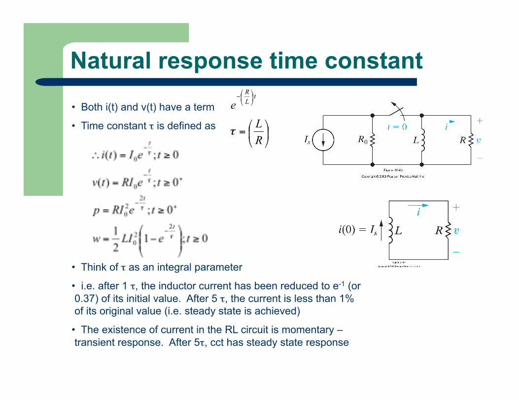
Natural response time constant
• Both i(t) and v(t) have a term
• Time constant τ is defined as
• Think of τ as an integral parameter
• i.e. after 1 τ, the inductor current has been reduced to e-1 (or 0.37) of its initial value. After 5 τ, the current is less than 1% of its original value (i.e. steady state is achieved)
• The existence of current in the RL circuit is momentary – transient response. After 5τ, cct has steady state response
19
Extracting τ
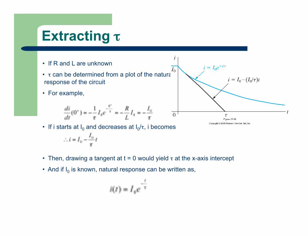
• If R and L are unknown
• τ can be determined from a plot of the natural response of the circuit
• For example,
• If i starts at I0 and decreases at I0/τ, i becomes
• Then, drawing a tangent at t = 0 would yield τ at the x-axis intercept
• And if I0 is known, natural response can be written as,
20
Example 7.1
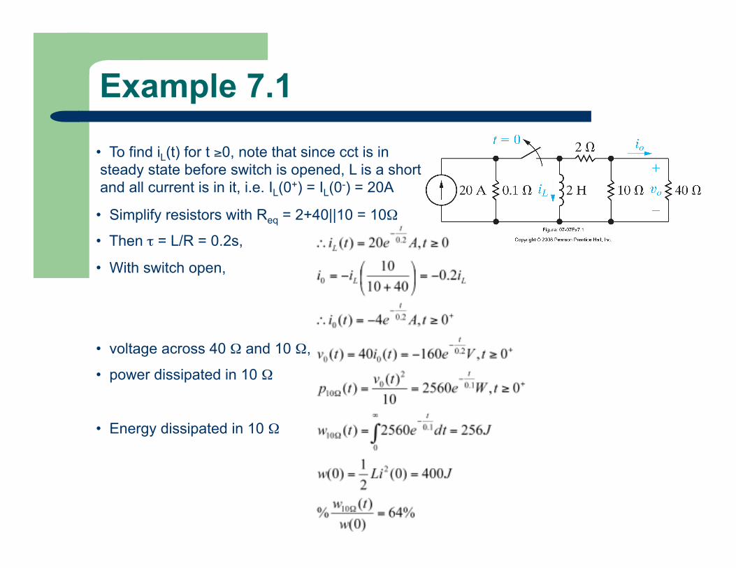
• To find iL(t) for t ≥0, note that since cct is in steady state before switch is opened, L is a short and all current is in it, i.e. IL(0+) = IL(0-) = 20A
• Simplify resistors with Req = 2+40||10 = 10Ω
• Then τ = L/R = 0.2s,
• With switch open,
• voltage across 40 Ω and 10 Ω,
• power dissipated in 10 Ω
• Energy dissipated in 10 Ω

21
Example 7.2 • Initial I in L1 and L2 already established by “hidden sources”
• To get i1, i2 and i3, find v(t) (since parallel cct) with simplified circuit
• Note inductor current i1 and i2 are valid from t ≥ 0 since current in inductor cannot change instantaneously
• However, resistor current i3 is valid only from t ≥ 0+ since there is 0 current in resistor at t = 0 (all I is shorted through inductors in steady state)

22
Example 7.2 (contd) • Initial energy stored in inductors
• Note wR + wfinal = winit
• wR indicates energy dissipated in resistors after switch opens
• wfinal is energy retained by inductors due to the current circulating between the two inductors (+1.6A and -1.6A) when they become short circuits at steady state again

23
Natural Response of RC circuit • Similar to that of an RL circuit • Assume all currents and voltages in circuit have reached steady state (constant, dc) values Prior to switch moving from a to b, • C is acting as open circuit (i.e. since at DC) • So all of Vg appears across C since I = 0 • We want to find v(t) for t>0 • Note that since voltage across capacitor cannot change instantaneously, Vg = V0, the initial voltage on capacitor
24
Example 7.3
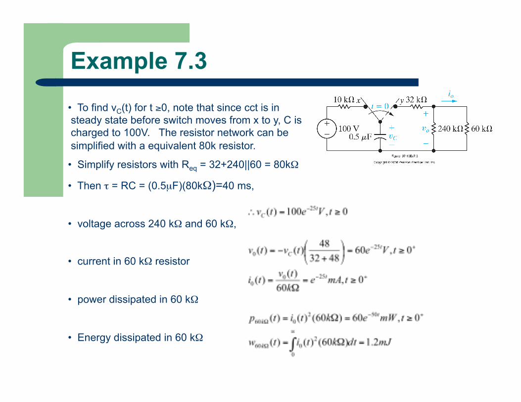
• To find vC(t) for t ≥0, note that since cct is in steady state before switch moves from x to y, C is charged to 100V. The resistor network can be simplified with a equivalent 80k resistor.
• Simplify resistors with Req = 32+240||60 = 80kΩ
• Then τ = RC = (0.5µF)(80kΩ)=40 ms,
• voltage across 240 kΩ and 60 kΩ,
• current in 60 kΩ resistor
• power dissipated in 60 kΩ
• Energy dissipated in 60 kΩ
25
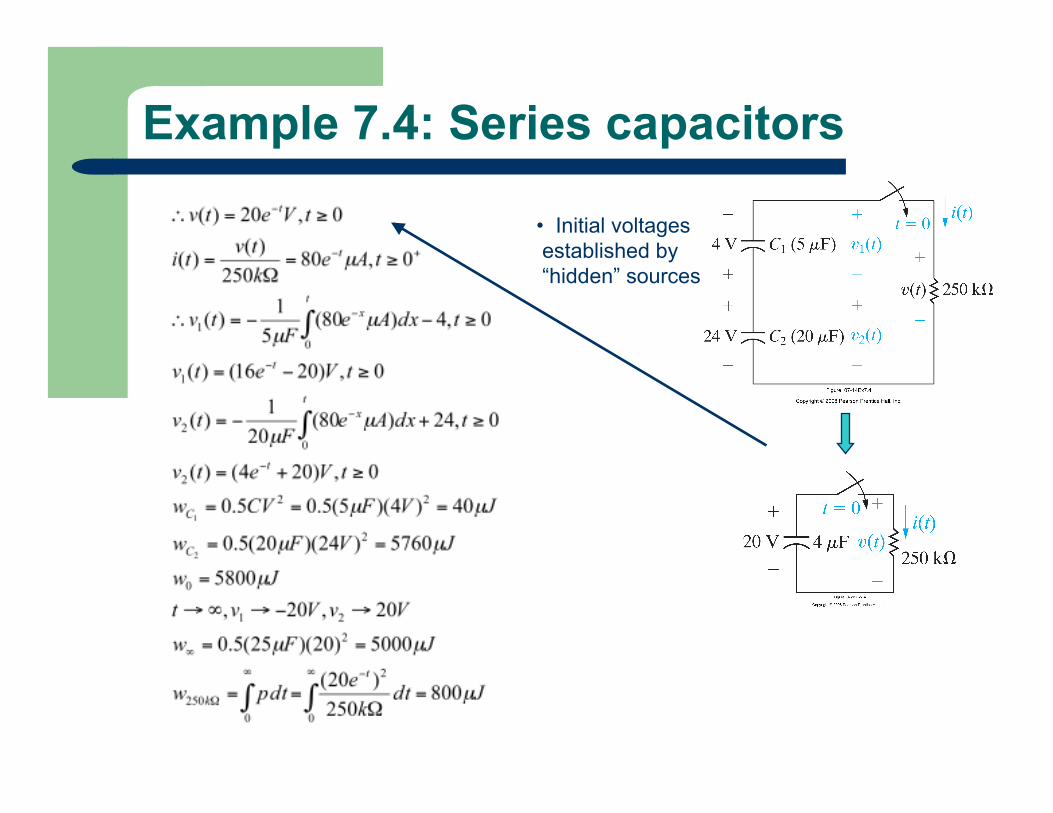
Example 7.4: Series capacitors
• Initial voltages established by “hidden” sources
26
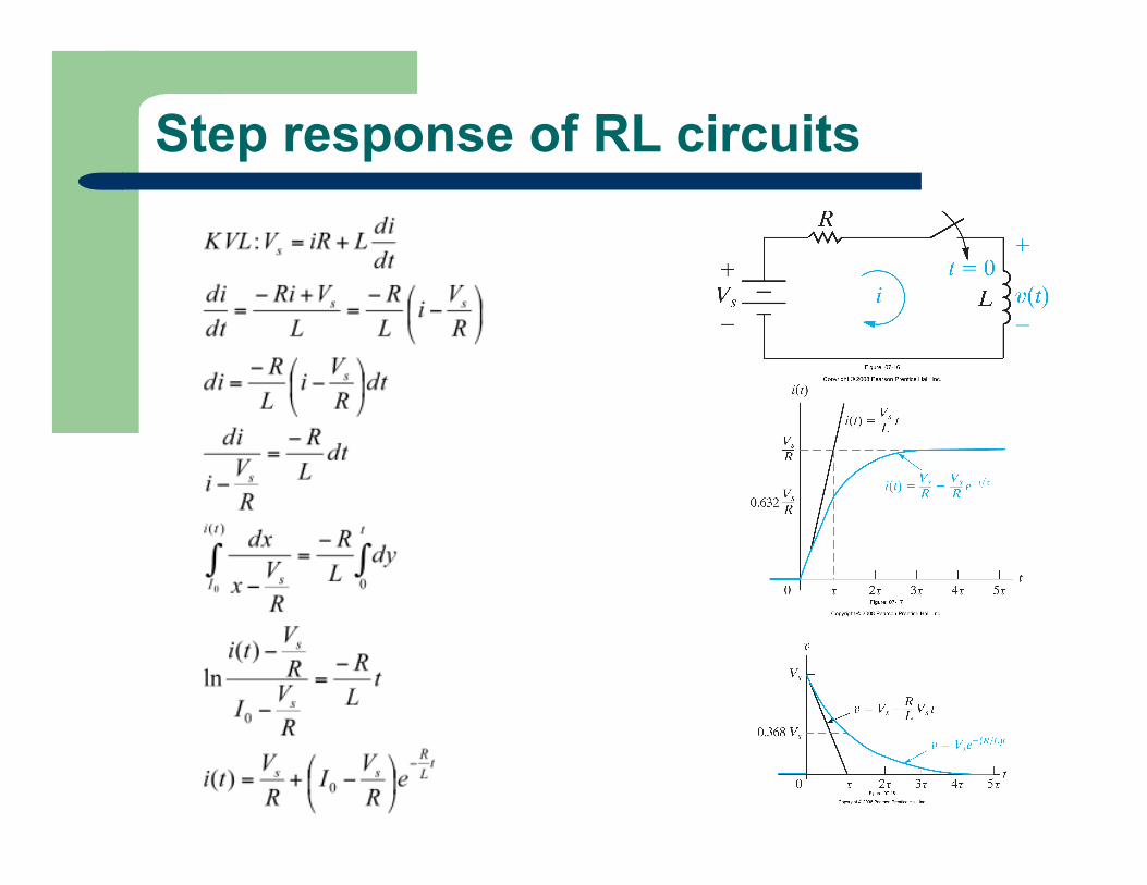
Step response of RL circuits
27
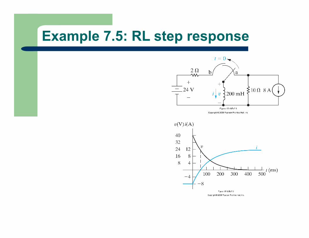
Example 7.5: RL step response
28
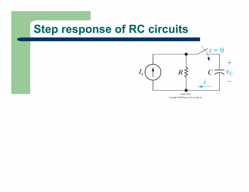
Step response of RC circuits

29
Example 7.6: RC Step Response