induction1 time varying circuits 2009 induction 2 the final exam approacheth 8-10 problems similar...
TRANSCRIPT

Induction 1
Time Varying CircuitsTime Varying Circuits
20092009

Induction Induction 22
The Final Exam ApproachethThe Final Exam Approacheth
8-10 Problems 8-10 Problems similar to Web-similar to Web-AssignmentsAssignments
Covers the entire Covers the entire semester’s worksemester’s work
May contain some May contain some short answer short answer (multiple choice) (multiple choice) questions.questions.

Induction Induction 33
Spring 2009 Final Exam ScheduleTuesday, April 28 - Monday, May 4No Exams on Sunday
EXAMTIMES
Class Meeting Times
EXAM DAY 1TUES 4/28
EXAM DAY 2WED 4/29
EXAM DAY 3THURS 4/30
EXAM DAY 4FRI 5/1
EXAM DAY 5SAT 5/2
EXAM DAY 6MON 5/4
7:00 a.m. -9:50 a.m.
7:30-10:20 T 9:00-10:15 TR (all a.m.)
7:30-10:20 W 8:30-9:20 MWF 9:00-10:15 MW (all a.m.)
7:30-8:45 TR 7:30-10:20 R (all a.m.)
7:30-10:20 F 9:00-10:15 M/7:30-8:45 F 9:30-10:20 MWF (all a.m.)
Finals For Saturday Classes Are Held During Regular Class Meeting Times
7:30-8:20 MWF 7:30-8:45 MW 7:30-10:20 M (all a.m.)
10:00 a.m. -12:50 p.m.
10:30-11:45 TR 10:30-1:20 T
10:30-1:20 W 11:30-12:20 MWF 12:00-1:15 MW 12:00-1:15 WF
10:30-1:20 R 12:00-1:15 TR
10:30-1:20 F 12:30-1:20 MWF 12:00-1:15 M/10:30-11:45 F
Finals For Saturday Classes Are Held During Regular Class Meeting Times
10:30-11:20 MWF 10:30-11:45 MW 10:30-1:20 M
1:00 p.m. -3:50 p.m.
1:30-2:45 TR 1:30-4:20 T
1:30-4:20 W 2:30-3:20 MWF 3:00-4:15 WF 3:00-4:15 MW
1:30-4:20 R 3:00-4:15 TR
1:30-4:20 F 3:30-4:20 MWF 3:00-4:15 M/1:30-2:45 F
FREE PERIOD1:30-2:20 MWF 1:30-2:45 MW 1:30-4:20 M
4:00 p.m. -6:50 p.m.
6:00-7:15 TRand Alternate Time
6:00-7:15 MWand Alternate Time
4:30-5:45 TRand Alternate Time
4:30-7:15 Fand Alternate Time
FREE PERIOD4:30-5:45 MWand Alternate Time
7:00 p.m. -9:50 p.m.
6:00-8:50 T 7:30-10:20 T (all p.m.)
6:00-8:50 W 7:00-7:50 MWF 7:30-8:45 MW 7:30-10:20 W (all p.m.)
6:00-8:50 R 7:30-8:45 TR 7:30-10:20 R (all p.m.)
6:00-8:50 F 8:00-8:50 MWF (all p.m.)
FREE PERIOD6:00-6:50 MWF 6:00-8:50 M 7:30-10:20 M (all p.m.)

HowjaDo??
Induction 4
A. I done goodB. I done okC. I done not so okD. I screwed up major

The Test Itself Was
Induction 5
A. FairB. Not so fair.C. Really Unfair.D. The worst kind of unfair in the entire
universe.

Back to Circuits for a bit ….
Sort of like RC circuit issues.

Definition
Current in loop produces a magnetic fieldin the coil and consequently a magnetic flux.
If we attempt to change the current, an emfwill be induced in the loops which will tend tooppose the change in current.
This this acts like a “resistor” for changes in current!

Remember Faraday’s Law
dt
ddVemf
sE
Lentz

Look at the following circuit:
Switch is open NO current flows in the circuit. All is at peace!

Close the circuit…
After the circuit has been close for a long time, the current settles down.
Since the current is constant, the flux through
the coil is constant and there is no Emf. Current is simply E/R (Ohm’s Law)

Close the circuit…
When switch is first closed, current begins to flow rapidly.
The flux through the inductor changes rapidly. An emf is created in the coil that opposes the
increase in current. The net potential difference across the resistor
is the battery emf opposed by the emf of the coil.

Close the circuit…
dt
demf
0
)(
dt
diRV
notationVEbattery

Moving right along …
0
solonoid, aFor
N. turns,ofnumber the toas wellas
current the toalproportion isflux The
0
)(
dt
diLiRV
dt
diL
dt
d
NLii
dt
diRV
notationVE
B
battery

Definition of Inductance L
i
NL B
UNIT of Inductance = 1 henry = 1 T- m2/A
is the flux near the center of one of the coilsmaking the inductor

Consider a Solenoid
n turns per unit lengthniB
or
nliBl
id enclosed
0
0
0
sBl

So….
AnlL
or
AlnL
ori
niAnl
i
nlBA
i
NL B
2
20
0
lengthunit
inductance/
Depends only on geometry just like C andis independent of current.

Inductive Circuit Switch to “a”. Inductor seems like a
short so current rises quickly.
Field increases in L and reverse emf is generated.
Eventually, i maxes out and back emf ceases.
Steady State Current after this.
i

THE BIG INDUCTION
As we begin to increase the current in the coil The current in the first coil produces a
magnetic field in the second coil Which tries to create a current which will
reduce the field it is experiences And so resists the increase in current.

Back to the real world…
i
0
equationcapacitor
theas form same
0
:0 drops voltageof sum
dt
dqR
C
qE
dt
diLiRE
Switch to “a”

Solution (See textbook)
R
L
eR
Ei LRt
constant time
)1( /

Switch position “b”
/
0
0
teR
Ei
iRdt
diL
E

Max Current Rate ofincrease = max emfVR=iR
~current

constant) (time
)1( /
R
L
eR
Ei LRt
Solve the lo
op equation.

IMPORTANT QUESTION
Switch closes. No emf Current flows for a while It flows through R Energy is conserved
(i2R)
WHERE DOES THE ENERGY COME FROM??

For an answerReturn to the Big C
We move a charge dq from the (-) plate to the (+) one.
The (-) plate becomes more (-)
The (+) plate becomes more (+).
dW=Fd=dq x E x d+q -q
E=0A/d
+dq

The calc
2
0
2
020
2
00
22
0
2
00
00
2
1
eunit volum
energy
2
1
2
1
2
1)(
2
2
)()()(
E
E
u
AdAdAd
AA
dW
or
q
A
dqdq
A
dW
dA
qdqddqEddqdW
The energy is inthe FIELD !!!

What about POWER??
Ridt
diLiiE
i
iRdt
diLE
2
:
powerto
circuit
powerdissipatedby resistor
Must be dWL/dt

So
2
2
2
12
1
CVW
LiidiLW
dt
diLi
dt
dW
C
L
L
Energystoredin the
Capacitor

WHERE is the energy??
l
Al
NiBA
l
Ni
niB
nilBll
id enclosed
0
0
0
0
0
B
or
0
sB

Remember the Inductor??
turn.onegh flux throu MagneticΦ
current.
inductorin turnsofNumber
i
Ni
NL

So …
l
AiN
l
NiANiW
l
NiA
iNi
NiLiW
L
Ni
i
NL
2220
0
0
0
22
2
1
2
1
2
1
2
1
2
1

2
0
2
0
22
0
0
2220
0
2
1
or
(volume) 2
1
2
1
B
:before From
2
1
BV
Wu
VBl
AlBW
l
Ni
l
AiNW
ENERGY IN THEFIELD TOO!

IMPORTANT CONCLUSION
A region of space that contains either a magnetic or an electric field contains electromagnetic energy.
The energy density of either is proportional to the square of the field strength.

Solution (From Before)
R
L
eR
Ei LRt
constant time
)1( /

At t=0, the charged capacitor is now connected to the inductor. What would you expect to happen??
Induction 35

The math …
Induction 36
2/12
2max
2
2
2
1
)cos(
:
0
0
L
R
LC
where
teQQ
Solutiondt
QdL
C
Q
dt
dQR
dt
diL
C
QiR
d
dL
Rt
For an RLC circuit with no driving potential (AC or DC source):

The Graph of that LR (no emf) circuit
Induction 37
L
Rt
e 2
L
Rt
e 2
I

Induction 38

Mass on a Spring Result
Induction 39
Energy will swap back and forth. Add friction Oscillation will slow down Not a perfect analogy

Induction 40

LC Circuit
Induction 41
High
Q/CLow
Low
High

The Math Solution (R=0):
LC
Induction 42

New Feature of Circuits with L and C
Induction 43
These circuits produce oscillations in the currents and voltages
Without a resistance, the oscillations would continue in an un-driven circuit.
With resistance, the current would eventually die out.

Variable Emf Applied
Induction 44
-1.5
-1
-0.5
0
0.5
1
1.5
0 1 2 3 4 5 6 7 8 9 10
Time
Vo
lts
emf
Sinusoidal
DC

Sinusoidal Stuff
Induction 45
)sin( tAemf
“Angle”
Phase Angle

Induction 46
Same Frequencywith
PHASE SHIFT

Different Frequencies
Induction 47

Note – Power is delivered to our homes as an oscillating source (AC)
Induction 48

Producing AC Generator
Induction 49
x x x x x x x x x x x x x x x x x x x x x x xx x x x x x x x x x x x x x x x x x x x x x xx x x x x x x x x x x x x x x x x x x x x x xx x x x x x x x x x x x x x x x x x x x x x xx x x x x x x x x x x x x x x x x x x x x x xx x x x x x x x x x x x x x x x x x x x x x xx x x x x x x x x x x x x x x x x x x x x x xx x x x x x x x x x x x x x x x x x x x x x xx x x x x x x x x x x x x x x x x x x x x x xx x x x x x x x x x x x x x x x x x x x x x xx x x x x x x x x x x x x x x x x x x x x x xx x x x x x x x x x x x x x x x x x x x x x x

The Real World
Induction 50

Induction 51
A

Induction 52

The Flux:
Induction 53
tAR
emfi
tBAemf
t
BA
bulb
sin
sin
cos
AB

problems …
Induction 54

Induction 55
14. Calculate the resistance in an RL circuit in which L = 2.50 H and the current increases to 90.0% of its final value in 3.00 s.

Induction 56
18. In the circuit shown in Figure P32.17, let L = 7.00 H, R = 9.00 Ω, and ε = 120 V. What is the self-induced emf 0.200 s after the switch is closed?

Induction 57
32. At t = 0, an emf of 500 V is applied to a coil that has an inductance of 0.800 H and a resistance of 30.0 Ω. (a) Find the energy stored in the magnetic field when the current reaches half its maximum value. (b) After the emf is connected, how long does it take the current to reach this value?

Induction 58
16. Show that I = I0 e – t/τ is a solution of the differential equation where τ = L/R and I0 is the current at t = 0.

Induction 59
17. Consider the circuit in Figure P32.17, taking ε = 6.00 V, L = 8.00 mH, and R = 4.00 Ω. (a) What is the inductive time constant of the circuit? (b) Calculate the current in the circuit 250 μs after the switch is closed. (c) What is the value of the final steady-state current? (d) How long does it take the current to reach 80.0% of its maximum value?

Induction 60
27. A 140-mH inductor and a 4.90-Ω resistor are connected with a switch to a 6.00-V battery as shown in Figure P32.27. (a) If the switch is thrown to the left (connecting the battery), how much time elapses before the current reaches 220 mA? (b) What is the current in the inductor 10.0 s after the switch is closed? (c) Now the switch is quickly thrown from a to b. How much time elapses before the current falls to 160 mA?

Induction 61
52. The switch in Figure P32.52 is connected to point a for a long time. After the switch is thrown to point b, what are (a) the frequency of oscillation of the LC circuit, (b) the maximum charge that appears on the capacitor, (c) the maximum current in the inductor, and (d) the total energy the circuit possesses at t = 3.00 s?

Source Voltage:
Induction 62
)sin(0 tVVemf

Induction 63
Average value of anything:
Area under the curve = area under in the average box
T
T
dttfT
h
dttfTh
0
0
)(1
)(
T
h

Average Value
Induction 64
0sin1
0
0 T
dttVT
V
T
dttVT
V0
)(1
For AC:

So …
Induction 65
Average value of current will be zero. Power is proportional to i2R and is ONLY
dissipated in the resistor, The average value of i2 is NOT zero because it
is always POSITIVE

Average Value
Induction 66
0)(1
0
T
dttVT
V
2VVrms

RMS
Induction 67
2
2)(
2
2)
2(
2
1
)2
(1
0
02
0
20
0
20
0
20
220
VV
VdSin
VV
tT
dtT
SinT
TVV
dttT
SinT
VtSinVV
rms
rms
T
rms
T
rms

Usually Written as:
Induction 68
2
2
rmspeak
peakrms
VV
VV

Example: What Is the RMS AVERAGE of the power delivered to the resistor in the circuit:
Induction 69
E
R
~

Power
Induction 70
tR
VRt
R
VRitP
tR
V
R
Vi
tVV
22
0
2
02
0
0
sin)sin()(
)sin(
)sin(

More Power - Details
Induction 71
R
VVV
RR
VP
R
VdSin
R
VP
tdtSinR
VP
dttSinTR
VP
tSinR
VtSin
R
VP
rms
T
T
200
20
20
2
0
22
0
0
22
0
0
22
0
22
022
0
22
1
2
1
2
1)(
2
1
)(1
2
)(1

Resistive Circuit
We apply an AC voltage to the circuit. Ohm’s Law Applies
Induction 72

Con
sid
er
this
cir
cuit
Induction 73
CURRENT ANDVOLTAGE IN PHASE
R
emfi
iRe

Induction 74

Induction 75
Alternating Current Circuits
is the angular frequency (angular speed) [radians per second].
Sometimes instead of we use the frequency f [cycles per second]
Frequency f [cycles per second, or Hertz (Hz)] f
V = VP sin (t -v ) I = IP sin (t -I )
An “AC” circuit is one in which the driving voltage andhence the current are sinusoidal in time.
v
V(t)
t
Vp
-Vp

Induction 76
v
V(t)
t
Vp
-Vp
V = VP sin (t - v )Phase Term

Induction 77
Vp and Ip are the peak current and voltage. We also use the
“root-mean-square” values: Vrms = Vp / and Irms=Ip /
v and I are called phase differences (these determine whenV and I are zero). Usually we’re free to set v=0 (but not I).
2 2
Alternating Current Circuits
V = VP sin (t -v ) I = IP sin (t -I )
v
V(t)
t
Vp
-Vp
Vrms
I/
I(t)
t
Ip
-Ip
Irms

Induction 78
Example: household voltage
In the U.S., standard wiring supplies 120 V at 60 Hz. Write this in sinusoidal form, assuming V(t)=0 at t=0.

Induction 79
Example: household voltage
In the U.S., standard wiring supplies 120 V at 60 Hz. Write this in sinusoidal form, assuming V(t)=0 at t=0.
This 120 V is the RMS amplitude: so Vp=Vrms = 170 V.2

Induction 80
Example: household voltage
In the U.S., standard wiring supplies 120 V at 60 Hz. Write this in sinusoidal form, assuming V(t)=0 at t=0.
This 120 V is the RMS amplitude: so Vp=Vrms = 170 V.This 60 Hz is the frequency f: so =2f=377 s -1.
2

Induction 81
Example: household voltage
In the U.S., standard wiring supplies 120 V at 60 Hz. Write this in sinusoidal form, assuming V(t)=0 at t=0.
This 120 V is the RMS amplitude: so Vp=Vrms = 170 V.This 60 Hz is the frequency f: so =2f=377 s -1.
So V(t) = 170 sin(377t + v).Choose v=0 so that V(t)=0 at t=0: V(t) = 170 sin(377t).
2

Induction 82
Review: Resistors in AC Circuits
ER
~EMF (and also voltage across resistor): V = VP sin (t)Hence by Ohm’s law, I=V/R:
I = (VP /R) sin(t) = IP sin(t) (with IP=VP/R)
V and I“In-phase”
V
t
I

Induction 83
This looks like IP=VP/R for a resistor (except for the phase change). So we call Xc = 1/(C) the Capacitive Reactance
Capacitors in AC Circuits
E
~C Start from: q = C V [V=Vpsin(t)]
Take derivative: dq/dt = C dV/dtSo I = C dV/dt = C VP cos (t)
I = C VP sin (t + /2)
The reactance is sort of like resistance in that IP=VP/Xc. Also, the current leads the voltage by 90o (phase difference).
V
t
I
V and I “out of phase” by 90º. I leads V by 90º.

Induction 84
I Leads V???What the **(&@ does that mean??
I
V
Current reaches it’s maximum at an earlier time than the voltage!
1
2
I = C VP sin (t +/2)
Phase=
-(/2)

Induction 85
Capacitor Example
E
~
CA 100 nF capacitor isconnected to an AC supply of peak voltage 170V and frequency 60 Hz.
What is the peak current?What is the phase of the current?
MX
f
C 65.2C
1
1077.3C
rad/sec 77.360227
Also, the current leads the voltage by 90o (phase difference).
I=V/XC

Induction 86
Again this looks like IP=VP/R for aresistor (except for the phase change).
So we call XL = L the Inductive Reactance
Inductors in AC Circuits
LV = VP sin (t)Loop law: V +VL= 0 where VL = -L dI/dtHence: dI/dt = (VP/L) sin(t).Integrate: I = - (VP / L cos (t)
or I = [VP /(L)] sin (t - /2)
~
Here the current lags the voltage by 90o.
V
t
I
V and I “out of phase” by 90º. I lags V by 90º.

Induction 87

Induction 88
Phasor Diagrams
Vp
Ipt
Resistor
A phasor is an arrow whose length represents the amplitude ofan AC voltage or current.
The phasor rotates counterclockwise about the origin with the angular frequency of the AC quantity.
Phasor diagrams are useful in solving complex AC circuits.The “y component” is the actual voltage or current.
A phasor is an arrow whose length represents the amplitude ofan AC voltage or current.
The phasor rotates counterclockwise about the origin with the angular frequency of the AC quantity.
Phasor diagrams are useful in solving complex AC circuits.The “y component” is the actual voltage or current.

Induction 89
Phasor Diagrams
Vp
Ipt
Vp
Ip
t
Resistor Capacitor
A phasor is an arrow whose length represents the amplitude ofan AC voltage or current.The phasor rotates counterclockwise about the origin with the angular frequency of the AC quantity.Phasor diagrams are useful in solving complex AC circuits.The “y component” is the actual voltage or current.
A phasor is an arrow whose length represents the amplitude ofan AC voltage or current.The phasor rotates counterclockwise about the origin with the angular frequency of the AC quantity.Phasor diagrams are useful in solving complex AC circuits.The “y component” is the actual voltage or current.

Induction 90
Phasor Diagrams
Vp
Ipt
Vp
IpVp Ip
Resistor Capacitor Inductor
A phasor is an arrow whose length represents the amplitude ofan AC voltage or current.The phasor rotates counterclockwise about the origin with the angular frequency of the AC quantity.Phasor diagrams are useful in solving complex AC circuits.The “y component” is the actual voltage or current.
A phasor is an arrow whose length represents the amplitude ofan AC voltage or current.The phasor rotates counterclockwise about the origin with the angular frequency of the AC quantity.Phasor diagrams are useful in solving complex AC circuits.The “y component” is the actual voltage or current.

Induction 91
Steady State Solution for AC Current (2)
• Expand sin & cos expressions
• Collect sindt & cosdt terms separately
• These equations can be solved for Im and (next slide)
1/ cos sin 0
1/ sin cos
d d
m d d m m
L C R
I L C I R
sin sin cos cos sin
cos cos cos sin sin
d d d
d d d
t t t
t t t
High school trig!
cosdt terms
sindt terms
cos sin cos sinmm d d m d d m d
d
II L I R t t t
C

Induction 92
Steady State Solution for AC Current (2)
• Expand sin & cos expressions
• Collect sindt & cosdt terms separately
• These equations can be solved for Im and (next slide)
1/ cos sin 0
1/ sin cos
d d
m d d m m
L C R
I L C I R
sin sin cos cos sin
cos cos cos sin sin
d d d
d d d
t t t
t t t
High school trig!
cosdt terms
sindt terms
cos sin cos sinmm d d m d d m d
d
II L I R t t t
C

Induction 93
• Solve for and Im in terms of
• R, XL, XC and Z have dimensions of resistance
• Let’s try to understand this solution using “phasors”
Steady State Solution for AC Current (3)
1/tan d d L CL C X X
R R
m
mIZ
22L CZ R X X
L dX L
1/C dX CInductive “reactance”
Capacitive “reactance”
Total “impedance”
1/ cos sin 0
1/ sin cos
d d
m d d m m
L C R
I L C I R

Induction 94
REMEMBER Phasor Diagrams?
Vp
Ipt
Vp
Ip
t
Vp Ip
t
Resistor Capacitor Inductor
A phasor is an arrow whose length represents the amplitude ofan AC voltage or current.The phasor rotates counterclockwise about the origin with the angular frequency of the AC quantity.Phasor diagrams are useful in solving complex AC circuits.
A phasor is an arrow whose length represents the amplitude ofan AC voltage or current.The phasor rotates counterclockwise about the origin with the angular frequency of the AC quantity.Phasor diagrams are useful in solving complex AC circuits.

Induction 95
Reactance - Phasor Diagrams
Vp
Ipt
Vp
Ip
t
Vp Ip
t
Resistor Capacitor Inductor

Induction 96
“Impedance” of an AC Circuit
R
L
C~
The impedance, Z, of a circuit relates peakcurrent to peak voltage:
IV
Zpp (Units: OHMS)

Induction 97
“Impedance” of an AC Circuit
R
L
C~
The impedance, Z, of a circuit relates peakcurrent to peak voltage:
IV
Zpp (Units: OHMS)
(This is the AC equivalent of Ohm’s law.)

Induction 98
Impedance of an RLC Circuit
R
L
C~
As in DC circuits, we can use the loop method:
- VR - VC - VL = 0 I is same through all components.

Induction 99
Impedance of an RLC Circuit
R
L
C~
As in DC circuits, we can use the loop method:
- VR - VC - VL = 0 I is same through all components.
BUT: Voltages have different PHASES
they add as PHASORS.
Induction 100
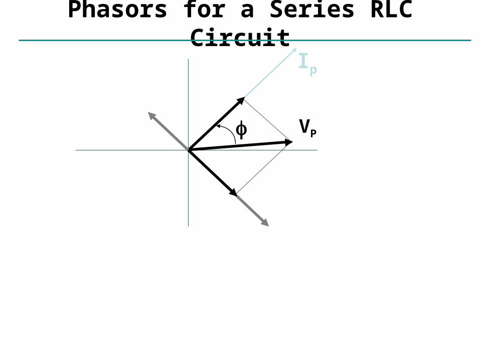
Phasors for a Series RLC Circuit
Ip
VRp
(VCp- VLp)
VP
VCp
VLp

Induction 101
Phasors for a Series RLC Circuit
By Pythagoras’ theorem:
(VP )2 = [ (VRp )2 + (VCp - VLp)2 ]
Ip
VRp
(VCp- VLp)
VP
VCp
VLp

Induction 102
Phasors for a Series RLC Circuit
By Pythagoras’ theorem:
(VP )2 = [ (VRp )2 + (VCp - VLp)2 ]
= Ip2 R2 + (Ip XC - Ip XL)
2
Ip
VRp
(VCp- VLp)
VP
VCp
VLp

Induction 103
Impedance of an RLC Circuit
Solve for the current:
Ip Vp
R2 (Xc XL )2
Vp
Z
R
L
C~

Induction 104
Impedance of an RLC Circuit
Solve for the current:
Impedance:
Ip Vp
R2 (Xc XL )2
Vp
Z
Z R2 1
C L
2
R
L
C~

Induction 105
The circuit hits resonance when 1/C-L=0: r=1/When this happens the capacitor and inductor cancel each otherand the circuit behaves purely resistively: IP=VP/R.
Impedance of an RLC Circuit
Ip Vp
Z
Z R2 1
C L
2
The current’s magnitude depends onthe driving frequency. When Z is aminimum, the current is a maximum.This happens at a resonance frequency:
LC
The current dies awayat both low and highfrequencies.
IP
01 0
21 0
31 0
41 0
5
R = 1 0 0
R = 1 0
r
L=1mHC=10F

Induction 106
Phase in an RLC CircuitIp
VRp
(VCp- VLp)
VP
VCp
VLp
We can also find the phase:
tan = (VCp - VLp)/ VRp
or; tan = (XC-XL)/R.
or tan = (1/C - L) / R

Induction 107
Phase in an RLC Circuit
At resonance the phase goes to zero (when the circuit becomespurely resistive, the current and voltage are in phase).
IpVRp
(VCp- VLp)
VP
VCp
VLp
We can also find the phase:
tan = (VCp - VLp)/ VRp
or; tan = (XC-XL)/R.
or tan = (1/C - L) / R
More generally, in terms of impedance:
cos R/Z

Induction 108
Power in an AC Circuit
V(t) = VP sin (t)
I(t) = IP sin (t)
P(t) = IV = IP VP sin 2(t) Note this oscillates
twice as fast.
V
t
I
t
P
= 0
(This is for a purely resistive circuit.)

Induction 109
The power is P=IV. Since both I and V vary in time, sodoes the power: P is a function of time.
Power in an AC Circuit
Use, V = VP sin (t) and I = IP sin (t+) :
P(t) = IpVpsin(t) sin (t+)
This wiggles in time, usually very fast. What we usually care about is the time average of this:
PT
P t dtT
10
( ) (T=1/f )

Induction 110
Power in an AC Circuit
Now: sin( ) sin( )cos cos( )sin t t t

Induction 111
Power in an AC Circuit
P t I V t tI V t t t
P P
P P
( ) sin( )sin( )sin ( )cos sin( )cos( )sin
2
Now: sin( ) sin( )cos cos( )sin t t t

Induction 112
Power in an AC Circuit
P t I V t tI V t t t
P P
P P
( ) sin( )sin( )sin ( )cos sin( )cos( )sin
2
sin ( )
sin( ) cos( )
2 1
2
0
t
t t
Use:
and:
So P I VP P1
2cos
Now: sin( ) sin( )cos cos( )sin t t t

Induction 113
Power in an AC Circuit
P t I V t tI V t t t
P P
P P
( ) sin( )sin( )sin ( )cos sin( )cos( )sin
2
sin ( )
sin( ) cos( )
2 1
2
0
t
t t
Use:
and:
So P I VP P1
2cos
Now:
which we usually write as P I Vrms rms cos
sin( ) sin( )cos cos( )sin t t t

Induction 114
Power in an AC Circuit
P I Vrms rms cos goes from -900 to 900, so the average power is positive)
cos( is called the power factor.
For a purely resistive circuit the power factor is 1.When R=0, cos()=0 (energy is traded but not dissipated).Usually the power factor depends on frequency.

Induction 115
16. Show that I = I0 e – t/τ is a solution of the differential equation where τ = L/R and I0 is the current at t = 0.

Induction 116
17. Consider the circuit in Figure P32.17, taking ε = 6.00 V, L = 8.00 mH, and R = 4.00 Ω. (a) What is the inductive time constant of the circuit? (b) Calculate the current in the circuit 250 μs after the switch is closed. (c) What is the value of the final steady-state current? (d) How long does it take the current to reach 80.0% of its maximum value?

Induction 117
27. A 140-mH inductor and a 4.90-Ω resistor are connected with a switch to a 6.00-V battery as shown in Figure P32.27. (a) If the switch is thrown to the left (connecting the battery), how much time elapses before the current reaches 220 mA? (b) What is the current in the inductor 10.0 s after the switch is closed? (c) Now the switch is quickly thrown from a to b. How much time elapses before the current falls to 160 mA?

Induction 118
52. The switch in Figure P32.52 is connected to point a for a long time. After the switch is thrown to point b, what are (a) the frequency of oscillation of the LC circuit, (b) the maximum charge that appears on the capacitor, (c) the maximum current in the inductor, and (d) the total energy the circuit possesses at t = 3.00 s?