induction motor application guide - … · • there are two kinds of rotor types in 3-phase...
TRANSCRIPT

INDUCTION MOTOR
APPLICATION GUIDE
ROTATING MACHINERY DESIGN DEPT

Electro Electric Systems 1
Contents
1. Duty cycle
2. Rotor
3. Insulation class
4. Temperature rise
& Ambient temperature
5. Construction
6. Environment
7. Altitude
8. Enclosure
9. Degree of protection
10. Starting method
11. Starting duty
12. Load inertia
13. Coupling method
14. Bearing types
15. Test and Inspection
16. Accessories
17. Fill-in sheet for Inquiry
18. HHI’s Data Sheet

Electro Electric Systems 2
1. Duty cycle
• The rating shall be informed by customer so that the size of
motor can be decided correctly.
• If no designation is stated, rating for continuous applies.
S1:Continuous S2:Short time S3:Periodic

Electro Electric Systems 3
Ratings Duty type Motor size
1000kW S1-Continuous 450fr
1000kW S2-30min. 400fr
For example

Electro Electric Systems 4
2. Rotor
• There are two kinds of rotor types in 3-phase induction motor.
• In case of wound rotor motor, the external rotor resistance is
optional item.
Squirrel Cage Rotor Wound Rotor

Electro Electric Systems 5
Squirrel Cage
rotor
Wound
rotor
Speed control No
(‘Yes’ with inverter) Yes
Starting performance Low starting toque
High starting current
High starting torque
Low starting current
Maintenance Good Bad
Cost Low High
Features of each rotor type

Electro Electric Systems 6
3. Insulation class
• The insulation class is the thermal class of insulation system
applied for winding insulation.
• HHI’s standard insulation class is F class
• The higher insulation class like H class is non-standard of HHI.
Class B Class F Class H
Temperature limit 130 deg.C 155 deg.C 180 deg.C
Insulation class table

Electro Electric Systems 7
4. Temperature rise & Ambient temperature
• Temperature rise of winding can be determined by resistance
method or by embedded temperature detector.
Class B Class F Class H
Resistance method 80 deg.C 105 deg.C 125 deg.C
Embedded
temperature detector 90 deg.C 115 deg.C 135 deg.C
Amb.:40 deg.C
Temperature rise table
• The motor size is determined depending not on the
temperature value but on the temperature rise value. So, If
the ambient temperature increase, then the temperature rise
shall decrease by the same degree.

Electro Electric Systems 8
Class B
Ambient Temperature rise Temperature Motor size
40 deg.C 80 deg.C 120 deg.C Smaller
50 deg.C 70 deg.C 120 deg.C Larger
• So, even with the same temperature class, the motor sizes can be
different depending on the ambient temperature.
• In case of water cooled type, 25 deg.C of cooling water match 40 deg.C
of cooling air.
No. Type Factor
Ambient Temp.IC411,IC611 Cooling IC01 Cooling
1 40℃ 1.0 1.0
2 45℃ 0.95 0.96
3 50℃ 0.9 0.91
4 55℃ 0.84 0.86
5 60℃ 0.78 0.81
• De-rating Factor for Cooling Air Inlet Temperature

Electro Electric Systems 9
5. Construction
• Horizontal Constructions
B3 B5
• Vertical Constructions
B35
V1: Flange is a part of
endshield
V10: Flange is a part of
frame

Electro Electric Systems 10
6. Environment
• First of all, the enclosure should be selected considering the
environment.
• This is an information for additional precaution. (Ex, dust filter,
space heater, anti-absorption treatment etc.)

Electro Electric Systems 11
7. Altitude
• The motor temperature can be affected by the altitude where the motor
is installed.
• Upto 1000m, the former thermal criteria is applied.
• Above 1000m, the reduction of cooling effect due to the lower air
density is generally compensated by the reduction of max. ambient
temperature.
• However, for the detail design, there need the information both about
altitude and max. ambient temperature.
No. Type Factor
Site AltitudeIC411,IC611 Cooling IC01 Cooling
1 0m < S.A. ≤ 1,000m 1.0 1.0
2 1,000m < S.A. ≤ 1,500m 0.96 0.96
3 1,500m < S.A. ≤ 2,000m 0.92 0.93
4 2,000m < S.A. ≤ 2,500m 0.88 0.90
5 2,500m < S.A. ≤ 3,000m 0.84 0.86
6 3,000m < S.A. ≤ 3,500m 0.80 0.83
7 3,500m < S.A. ≤ 4,000m 0.76 0.80
##. De-rating Factor for site altitude

Electro Electric Systems 12
8. Enclosure
• Open Drip-proof(IP23)
-.An open machine in which the ventilating openings are so
constructed that successful operation is not interfered with
when drops of liquid or solid particles
-.Because of direct cooling, the motor size is small.
• NEMA Weather protected type II(IPW24)
-.Its ventilating passage so arranged that high velocity air born
particle can not enter inside motor.
-. Additional air housing on ODP motor.
• Totally Enclosed Fan Coold(IP44, IP54, IP55, IP56)
-.Totally enclosed machine equipped for self exterior cooling.
-. Because of indirect cooling, the motor size is large.

Electro Electric Systems 13
IP X X
Characteristics letters
1st characteristics numeral
2nd characteristics numeral
Example of designation
♦ The first characteristic numeral indicates the degree of protection provided by the enclosure to persons and to the parts of the machine inside the enclosure.
♦ The second characteristic numeral indicates the degree of protection provided by the enclosure with respect to harmful effects due to ingress of water.
9. Degree of protection

Electro Electric Systems 14
Degree of protection indicated by the first characteristic numeral
First characteristic
s numeral
Degree of Protection
Definition
0 No special protection
1
Accidental or inadvertent contact with or approach to live and moving parts inside the enclosure by a large surface of the human body, such as a hand (but no protection against deliberate access). Ingress of solid objects exceeding 50 mm in diameter
2 Contact with or approach to live or moving parts inside the enclosure by fingers or similar objects not exceeding 80 mm in length. Ingress of solid objects exceeding 12 mm in diameter
4 Contact with or approach to live or moving parts inside the enclosure by wires or strips of thickness greater than 1 mm. Ingress of solid objects exceeding 1 mm in diameter
5 Contact with or approach to live or moving parts inside the enclosure. Ingress of dust is not totally prevented but dust does not enter in sufficient quantity to interfere with satisfactory operation of the machine

Electro Electric Systems 15
Degree of protection indicated by the second characteristic numeral
Second characteristic
s numeral
Degree of Protection
Definition
0 No special protection
1 Dripping water (vertically falling drops) shall have no harmful effect
2 Vertically dripping water shall no harmful effect when the machine is tilted at any angle up to 15˚ from its normal position
3 Water falling as a spray at an angle up to 60˚ from the vertical shall have no harmful effect
4 Water splashing against the machine from any direction shall have no harmful effect
5 Water projected by a nozzle against the machine from any direction shall have no harmful effect
6 Water from heavy seas or water projected in powerful jets shall not enter the machine in harmful quantities
Electro Electric Systems 16
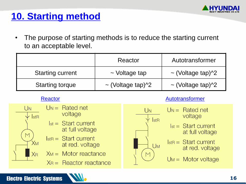
10. Starting method
• The purpose of starting methods is to reduce the starting current
to an acceptable level.
Reactor Autotransformer
Starting current ~ Voltage tap ~ (Voltage tap)^2
Starting torque ~ (Voltage tap)^2 ~ (Voltage tap)^2
Reactor Autotransformer
Electro Electric Systems 17
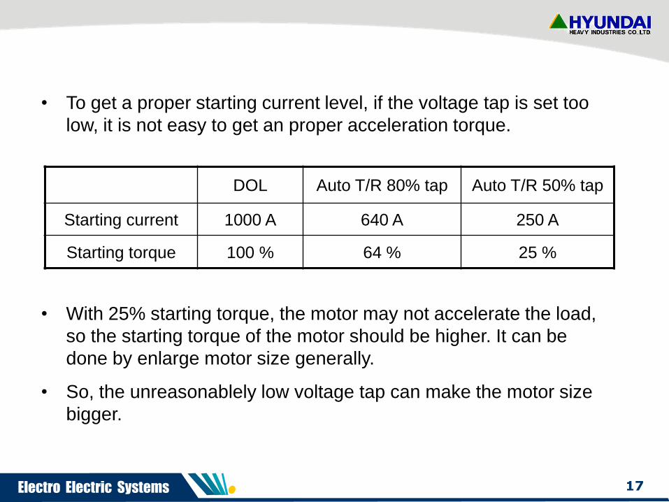
• To get a proper starting current level, if the voltage tap is set too
low, it is not easy to get an proper acceleration torque.
DOL Auto T/R 80% tap Auto T/R 50% tap
Starting current 1000 A 640 A 250 A
Starting torque 100 % 64 % 25 %
• With 25% starting torque, the motor may not accelerate the load,
so the starting torque of the motor should be higher. It can be
done by enlarge motor size generally.
• So, the unreasonablely low voltage tap can make the motor size
bigger.

Electro Electric Systems 18
0 10 20 30 40 50 60 70 80 90 1000
20
40
60
80
100
120
140
160
180
200
220
240
260
280
0
50
100
150
200
250
300
350
400
450
500
550
600
650
700
Speed[%]
To
rqu
e[%
]
Cu
rren
t[%
]
• If the load torque curve is provided, the acceleration
characteristics can be checked with the given voltage tap.
Speed-torque & current curve
B
A
C
D
L
A: Speed vs torque curve at 100% voltage
B: Speed vs current curve at 100% voltage
C: Speed vs torque curve at 50% voltage
D: Speed vs current curve at 50% voltage
L: Speed vs load torque curve
Max.torque
Starting
torque
The acceleration at 75% speed is
impossible with 50% voltage tap.

Electro Electric Systems 19
11. Starting duty
1) Starting a motor cause a great stress on motor mechanically,
electrically, and thermally. So, If possible, the frequent starts of
motor should not be allowed.
2) NEMA MG1 give a criteria as below
• Two Starts in succession with the motor initially at an ambient
temperature.(Cold condition)
• One Start with the motor initially at a full load temperature.(Hot
condition)
• It should be recognized that the number of starts should be kept
a minimum since the life of the motor is affected by the number
of starts.

Electro Electric Systems 20
12. Load inertia
J: Inertia moment
T: Acceleration Torque
1) The higher load inertia the longer starting time
the higher temperature
during starting.
the lower starting duty.
• In case of high inertia load, the motor size should be enlarged to
dissipate the heat generated during starting.

Electro Electric Systems 21
• With the same motor, we can have the different curves
depending on the loads.
Thermal limit & Time current curve
1 2 3 4 5 61
10
100
1000
Current[pu]
Tim
e[s
ec]
Fan Pump
1 2 3 4 5 61
10
100
1000
Current[pu]
Tim
e[s
ec]

Electro Electric Systems 22
13. Coupling method
• Hydraulic coupling
-. If hydraulic coupling is used, the inertia of load do not effected on
motor during starting.
-. So, if hydraulic coupling is adopted to high inertia load, then the
motor can be sized like standard inertia motor.

Electro Electric Systems 23
14. Bearing types
• HHI’s standard bearing types are stated on HHI motor catalog.
• If the bearing type change from anti-friction bearing to sleeve bearing,
the additional cost shall be requested.
• The sleeve bearing applied on HHI motor catalog is the forced cooled
type. So, if the self cooled type is necessary, the non-standard motor
may be applied.
Anti-friction bearing Sleeve bearing
Electro Electric Systems 24
15. Test and Inspection
• The applicable test standards are
-. NEMA MG1, API 541, IEC 60034, JEC 2137, IEEE 112 etc.
• HHI’s standard inspection plan is non-witness routine test with one
motor temperature rise test.
• Standard test items
-. Dimensional inspection
-. No load test & Locked rotor test
-. Determination of characteristics (Efficiency, power factor, torque..)
-. Noise test & Vibration test
-. Heat run test (Temperature rise test)
-. Insulation resistance test & High voltage test

Electro Electric Systems 25
• According to the limit of test facility of HHI, the below matters are
usually deviated like followings.
-. Actual loading test Equivalent loading test according to IEC,
IEEE 112
-. Efficiency and power factor measurement Measurement for
calculation by equivalent circuit method according to IEEE 112,
JEC 2137, IEC 60034-2
-. Starting current and starting torque measurement
Measurement for calculation by Locked rotor test according to
IEEE 112
• Optional items are
-. Insulation diagnosis (PD, Tan-delta, etc.)
-. Water immersion test
-. Terminal box fault level test

Electro Electric Systems 26
16. Accessories
• Temperature detectors (RTD, Thermocouple)
-. WTD(Winding temperature detector)
-. BTD(Bearing temperature detector)
• Others
-. Differential CTs
-. Surge capacitor, Lighting arrestor
-. Air differential pressure switch
-. Proximity sensor (Shaft vibration), Velometer (Housing vibration)
-. Zero-speed switch, Reverse rotation sensor
-. PD coupler
-. Leakage detector

Electro Electric Systems 27
17. Fill-in sheet for inquiry

Electro Electric Systems 28

Electro Electric Systems 29
18. HHI’s Data Sheet

Electro Electric Systems 30

Electro Electric Systems 31
Thanks for your attention.