induction hardening of gears & sprockets -...
TRANSCRIPT
Induction Hardening of
Gears & Sprockets
Dr. Valentin Nemkov
A Joint Class of AGMA and ASM
Gear Expo 2013 September 19, 2013
Indianapolis
Overview
• Specifics and methods of induction gear hardening
• Single-shot aka Spin hardening
Single Frequency hardening
Dual Frequency hardening
Simultaneous Dual Frequency hardening
• Tooth Scan hardening (Delapena process)
• Tooth-by-Tooth simultaneous hardening
• Computer simulation
• Conclusions
SDF Hardened Gear, Eldec Induction
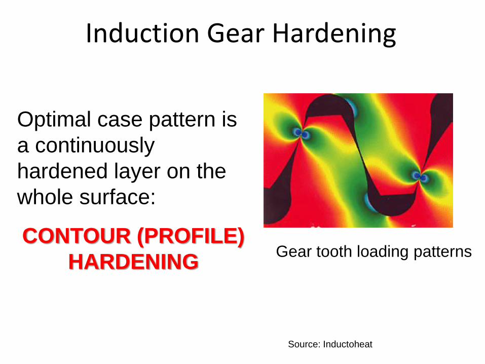
Induction Gear Hardening
Gear tooth loading patterns
Optimal case pattern is
a continuously
hardened layer on the
whole surface:
CONTOUR (PROFILE)
HARDENING
Source: Inductoheat
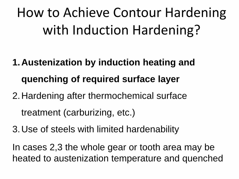
How to Achieve Contour Hardening with Induction Hardening?
1.Austenization by induction heating and
quenching of required surface layer
2.Hardening after thermochemical surface
treatment (carburizing, etc.)
3.Use of steels with limited hardenability
In cases 2,3 the whole gear or tooth area may be
heated to austenization temperature and quenched
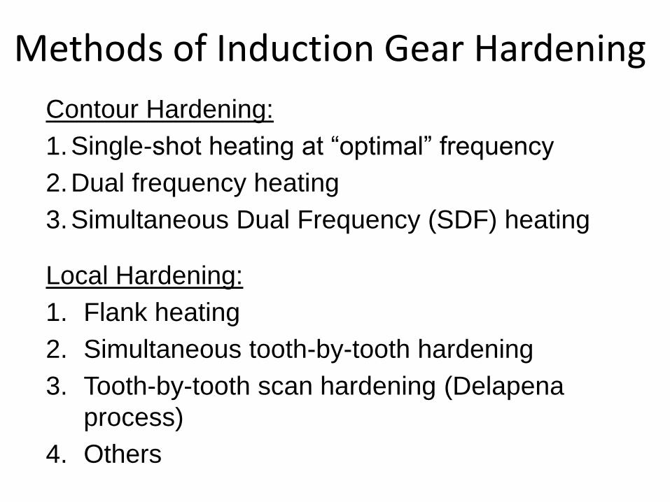
Methods of Induction Gear Hardening
Contour Hardening:
1.Single-shot heating at “optimal” frequency
2.Dual frequency heating
3.Simultaneous Dual Frequency (SDF) heating
Local Hardening:
1. Flank heating
2. Simultaneous tooth-by-tooth hardening
3. Tooth-by-tooth scan hardening (Delapena
process)
4. Others
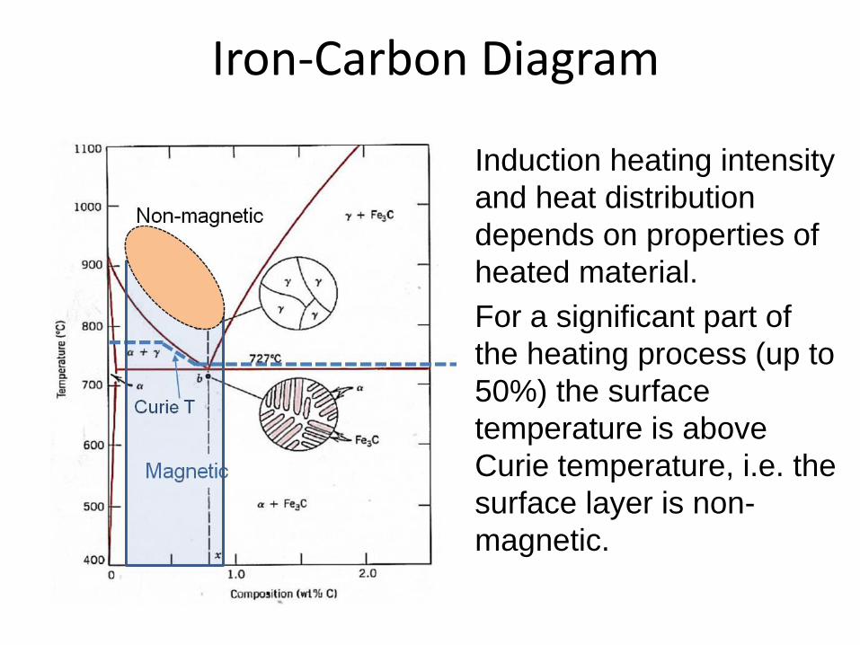
Iron-Carbon Diagram
Induction heating intensity
and heat distribution
depends on properties of
heated material.
For a significant part of
the heating process (up to
50%) the surface
temperature is above
Curie temperature, i.e. the
surface layer is non-
magnetic.
7
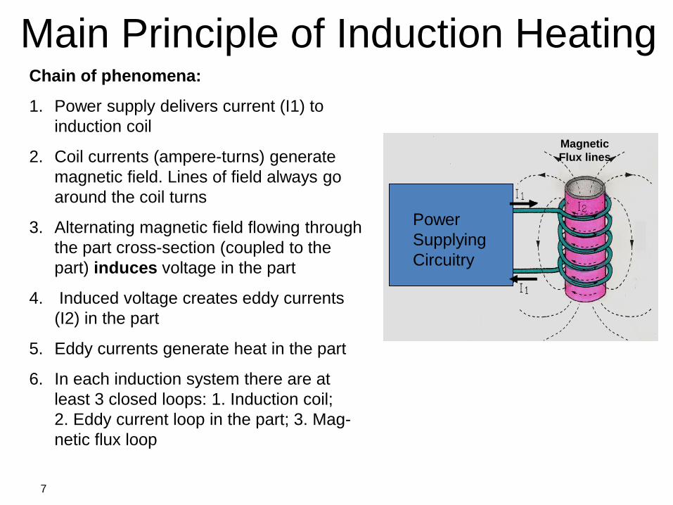
Main Principle of Induction Heating Chain of phenomena:
1. Power supply delivers current (I1) to
induction coil
2. Coil currents (ampere-turns) generate
magnetic field. Lines of field always go
around the coil turns
3. Alternating magnetic field flowing through
the part cross-section (coupled to the
part) induces voltage in the part
4. Induced voltage creates eddy currents
(I2) in the part
5. Eddy currents generate heat in the part
6. In each induction system there are at
least 3 closed loops: 1. Induction coil;
2. Eddy current loop in the part; 3. Mag-
netic flux loop
Magnetic
Flux lines
Power
Supplying
Circuitry
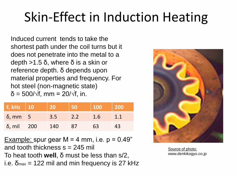
Skin-Effect in Induction Heating
Source of photo:
www.denkikogyo.co.jp
Induced current tends to take the
shortest path under the coil turns but it
does not penetrate into the metal to a
depth >1.5 δ, where δ is a skin or
reference depth. δ depends upon
material properties and frequency. For
hot steel (non-magnetic state)
δ = 500/√f, mm = 20/√f, in.
F, kHz 10 20 50 100 200
δ, mm 5 3.5 2.2 1.6 1.1
δ, mil 200 140 87 63 43
Example: spur gear M = 4 mm, i.e. p = 0.49”
and tooth thickness s = 245 mil
To heat tooth well, δ must be less than s/2,
i.e. δmax = 122 mil and min frequency is 27 kHz
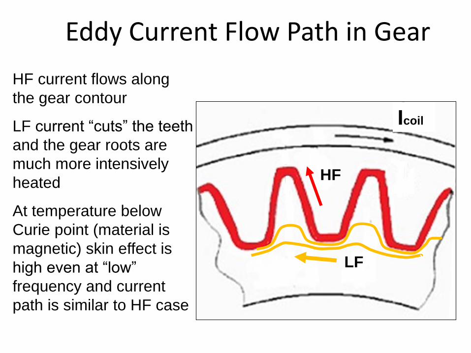
Eddy Current Flow Path in Gear
HF
LF
Icoil
HF current flows along
the gear contour
LF current “cuts” the teeth
and the gear roots are
much more intensively
heated
At temperature below
Curie point (material is
magnetic) skin effect is
high even at “low”
frequency and current
path is similar to HF case
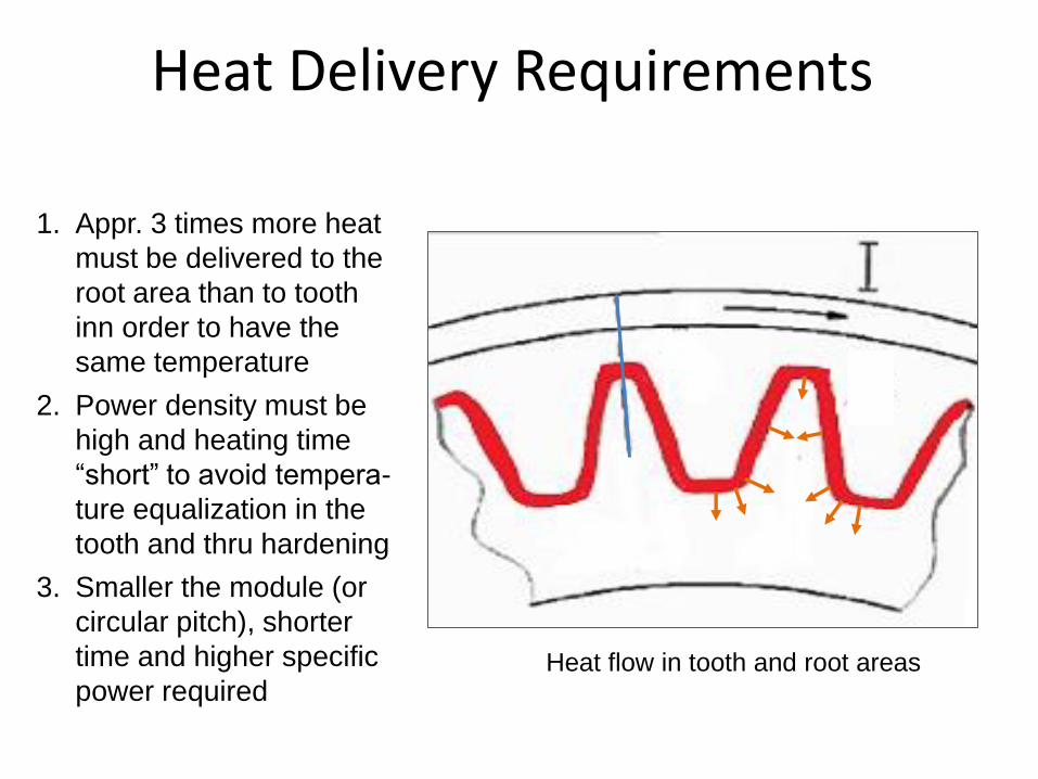
Heat Delivery Requirements
Heat flow in tooth and root areas
1. Appr. 3 times more heat
must be delivered to the
root area than to tooth
inn order to have the
same temperature
2. Power density must be
high and heating time
“short” to avoid tempera-
ture equalization in the
tooth and thru hardening
3. Smaller the module (or
circular pitch), shorter
time and higher specific
power required
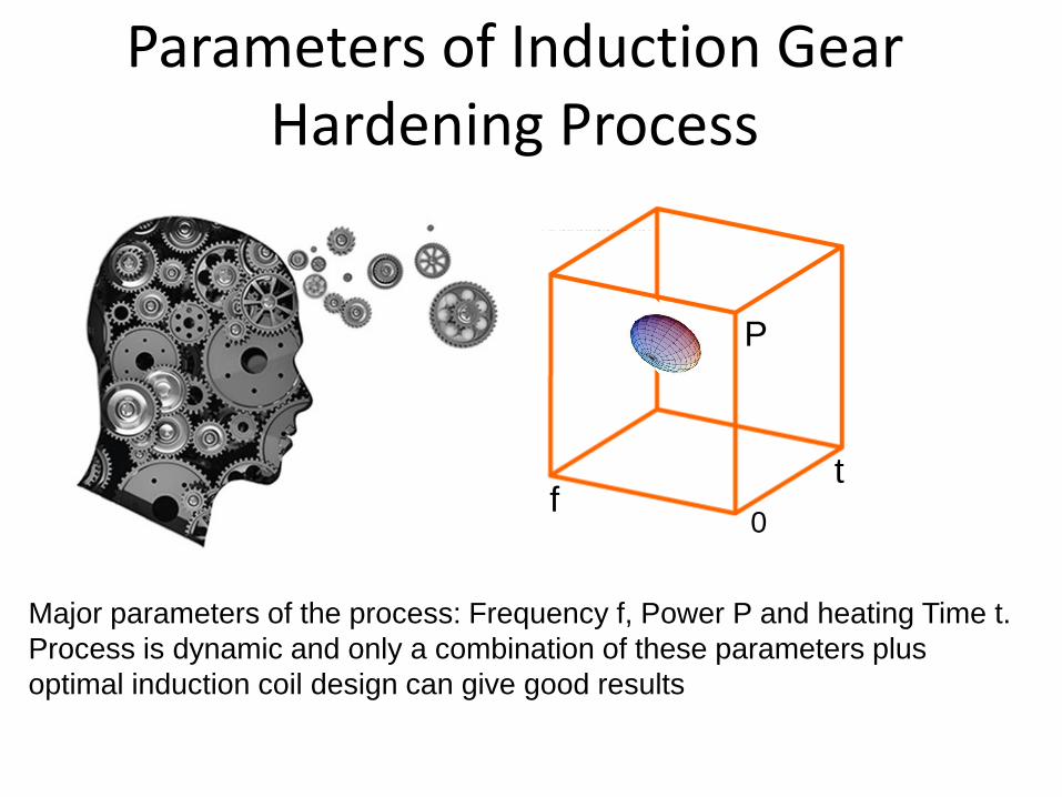
Parameters of Induction Gear Hardening Process
Major parameters of the process: Frequency f, Power P and heating Time t.
Process is dynamic and only a combination of these parameters plus
optimal induction coil design can give good results
f t
P
0
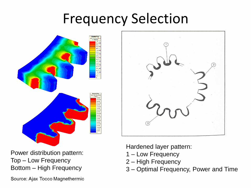
Frequency Selection
Hardened layer pattern:
1 – Low Frequency
2 – High Frequency
3 – Optimal Frequency, Power and Time
Power distribution pattern:
Top – Low Frequency
Bottom – High Frequency
Single-Shot Hardening aka
Spin Hardening
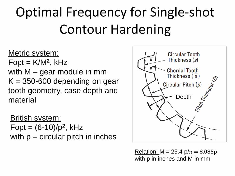
British system:
Fopt = (6-10)/p2, kHz
with p – circular pitch in inches
Metric system:
Fopt = K/M2, kHz
with M – gear module in mm
K = 350-600 depending on gear
tooth geometry, case depth and
material
Optimal Frequency for Single-shot Contour Hardening
Depth
Relation: M = 25.4 p/𝜋 = 8.085p with p in inches and M in mm
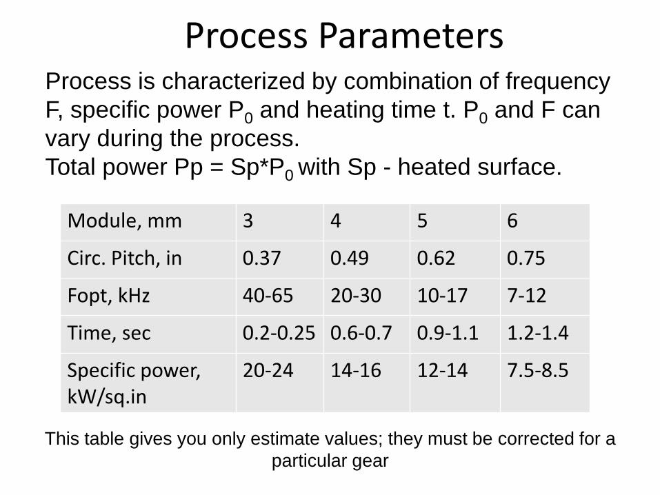
Module, mm 3 4 5 6
Circ. Pitch, in 0.37 0.49 0.62 0.75
Fopt, kHz 40-65 20-30 10-17 7-12
Time, sec 0.2-0.25 0.6-0.7 0.9-1.1 1.2-1.4
Specific power, kW/sq.in
20-24 14-16 12-14 7.5-8.5
Process Parameters Process is characterized by combination of frequency
F, specific power P0 and heating time t. P0 and F can
vary during the process.
Total power Pp = Sp*P0 with Sp - heated surface.
This table gives you only estimate values; they must be corrected for a
particular gear
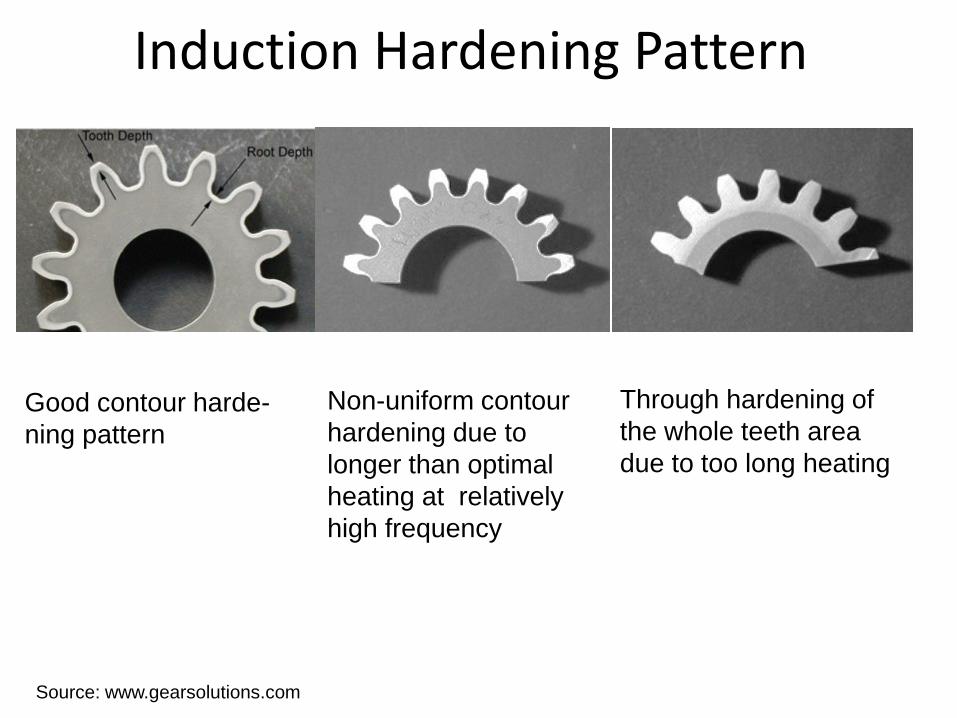
Induction Hardening Pattern
Source: www.gearsolutions.com
Through hardening of
the whole teeth area
due to too long heating
Non-uniform contour
hardening due to
longer than optimal
heating at relatively
high frequency
Good contour harde-
ning pattern
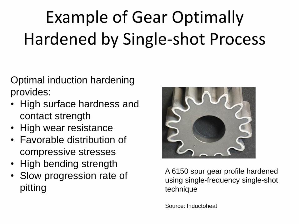
Example of Gear Optimally Hardened by Single-shot Process
A 6150 spur gear profile hardened
using single-frequency single-shot
technique
Source: Inductoheat
Optimal induction hardening
provides:
• High surface hardness and
contact strength
• High wear resistance
• Favorable distribution of
compressive stresses
• High bending strength
• Slow progression rate of
pitting
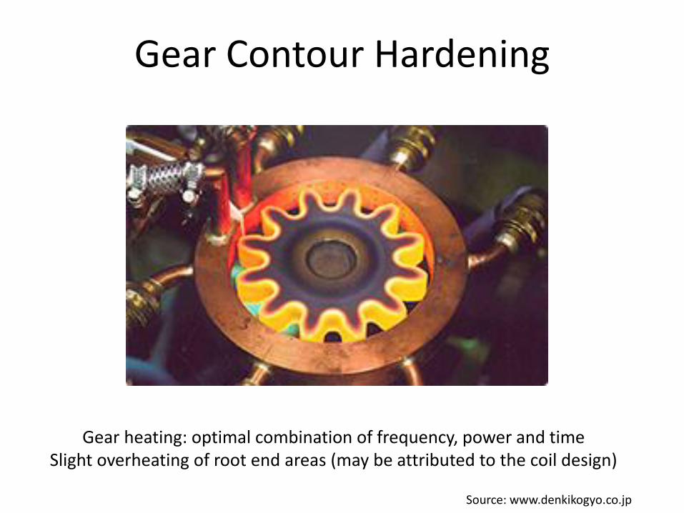
Gear Contour Hardening
Gear heating: optimal combination of frequency, power and time Slight overheating of root end areas (may be attributed to the coil design)
Source: www.denkikogyo.co.jp
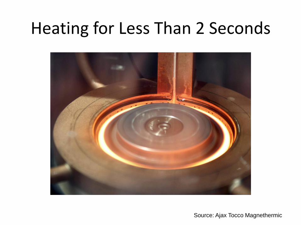
Heating for Less Than 2 Seconds
Source: Ajax Tocco Magnethermic
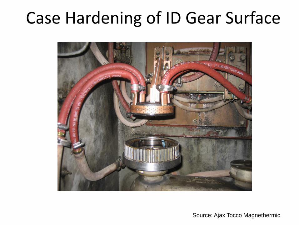
Case Hardening of ID Gear Surface
Source: Ajax Tocco Magnethermic
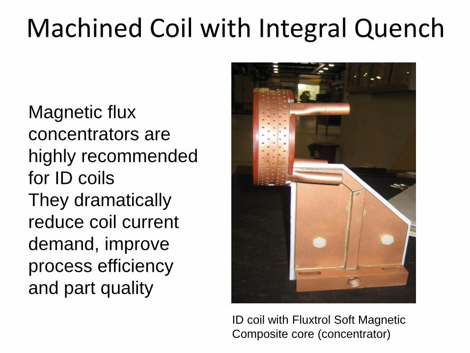
Machined Coil with Integral Quench
Magnetic flux
concentrators are
highly recommended
for ID coils
They dramatically
reduce coil current
demand, improve
process efficiency
and part quality
ID coil with Fluxtrol Soft Magnetic
Composite core (concentrator)
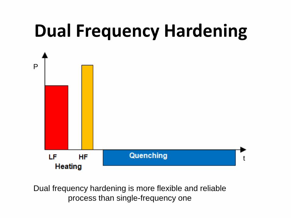
Dual Frequency Hardening
Dual frequency hardening is more flexible and reliable
process than single-frequency one
t
P
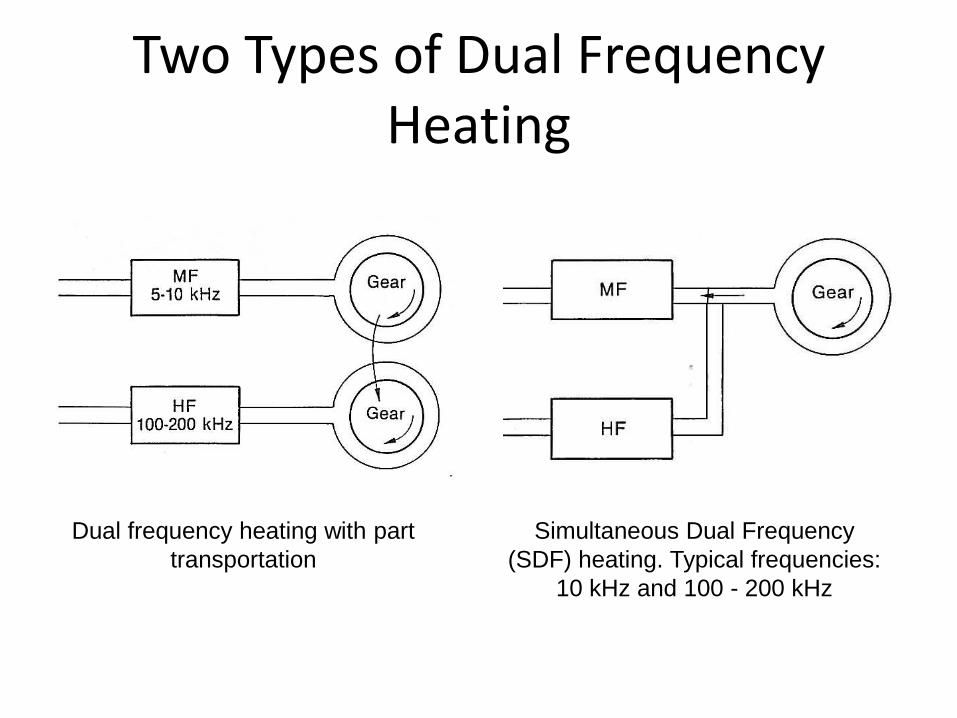
Two Types of Dual Frequency Heating
Dual frequency heating with part
transportation
Simultaneous Dual Frequency
(SDF) heating. Typical frequencies:
10 kHz and 100 - 200 kHz
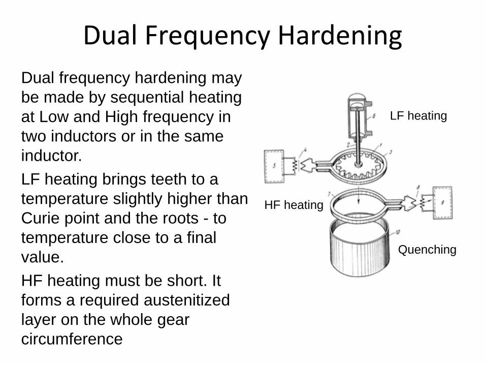
Dual Frequency Hardening
Dual frequency hardening may
be made by sequential heating
at Low and High frequency in
two inductors or in the same
inductor.
LF heating brings teeth to a
temperature slightly higher than
Curie point and the roots - to
temperature close to a final
value.
HF heating must be short. It
forms a required austenitized
layer on the whole gear
circumference
LF heating
HF heating
Quenching
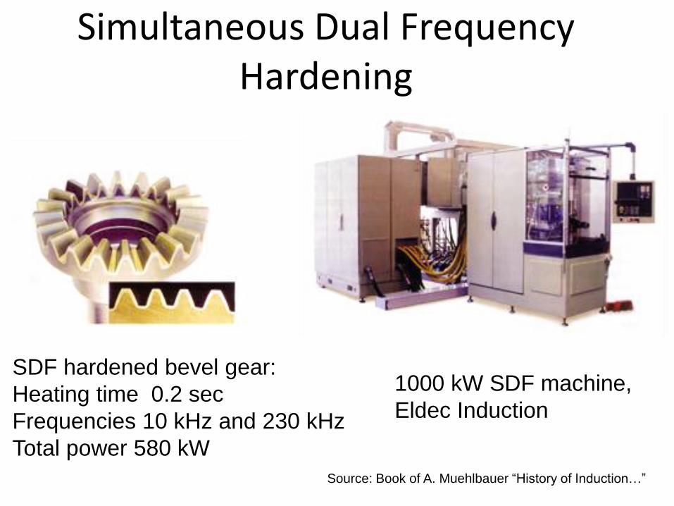
Simultaneous Dual Frequency Hardening
SDF hardened bevel gear:
Heating time 0.2 sec
Frequencies 10 kHz and 230 kHz
Total power 580 kW
1000 kW SDF machine,
Eldec Induction
Source: Book of A. Muehlbauer “History of Induction…”
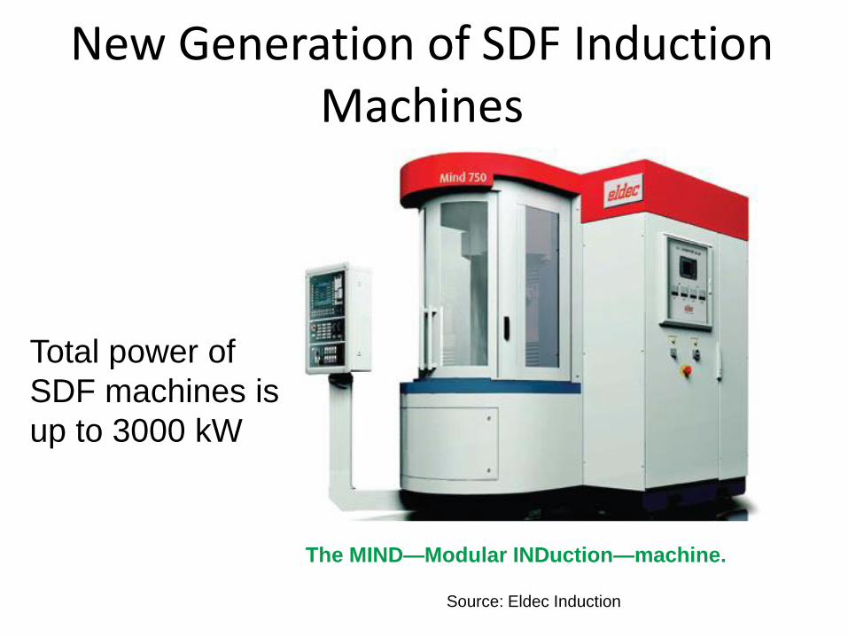
The MIND—Modular INDuction—machine.
Source: Eldec Induction
New Generation of SDF Induction Machines
Total power of
SDF machines is
up to 3000 kW

Scanning: Delapena Process
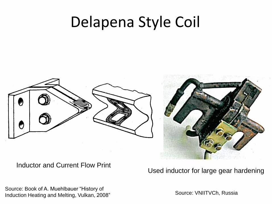
Delapena Style Coil
Inductor and Current Flow Print Used inductor for large gear hardening
Source: VNIITVCh, Russia Source: Book of A. Muehlbauer “History of
Induction Heating and Melting, Vulkan, 2008”
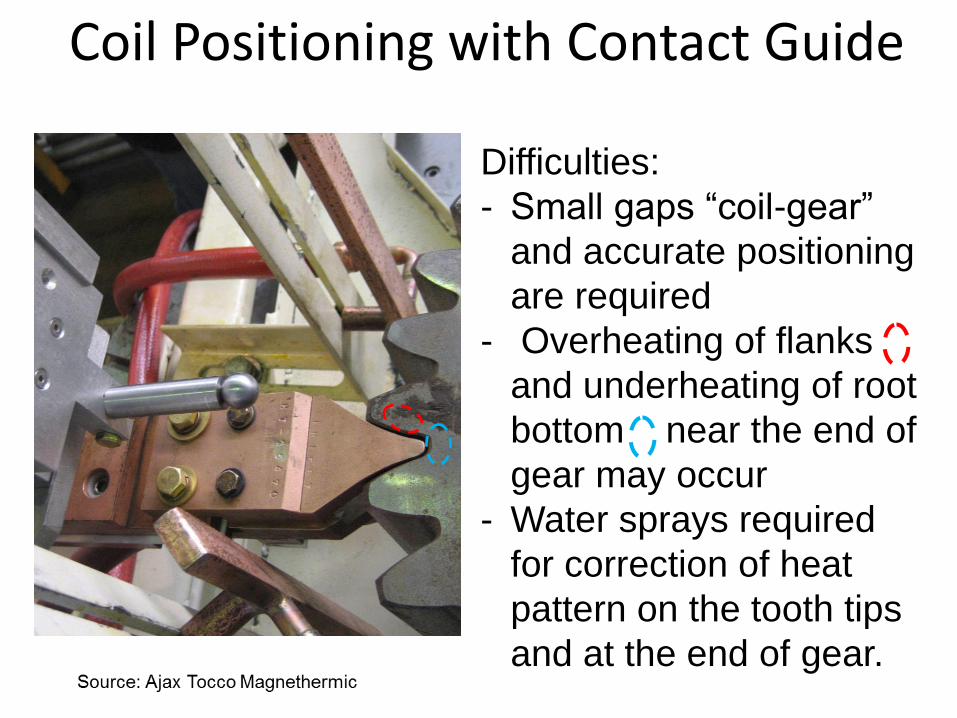
Coil Positioning with Contact Guide Difficulties:
- Small gaps “coil-gear”
and accurate positioning
are required
- Overheating of flanks
and underheating of root
bottom near the end of
gear may occur
- Water sprays required
for correction of heat
pattern on the tooth tips
and at the end of gear.
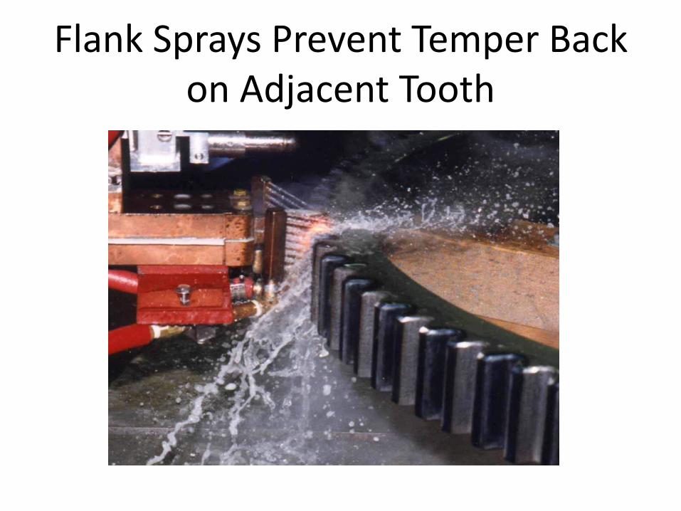
Flank Sprays Prevent Temper Back on Adjacent Tooth
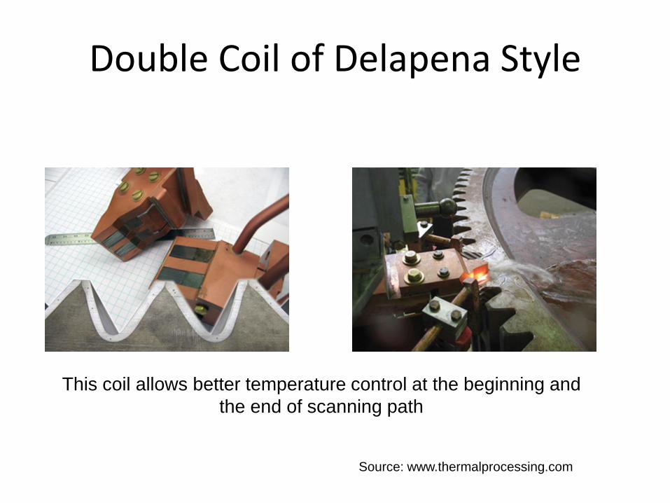
Double Coil of Delapena Style
Source: www.thermalprocessing.com
This coil allows better temperature control at the beginning and
the end of scanning path
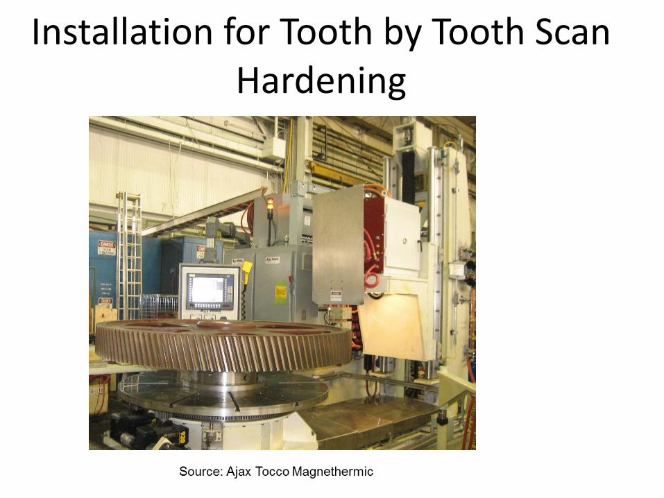
Installation for Tooth by Tooth Scan Hardening
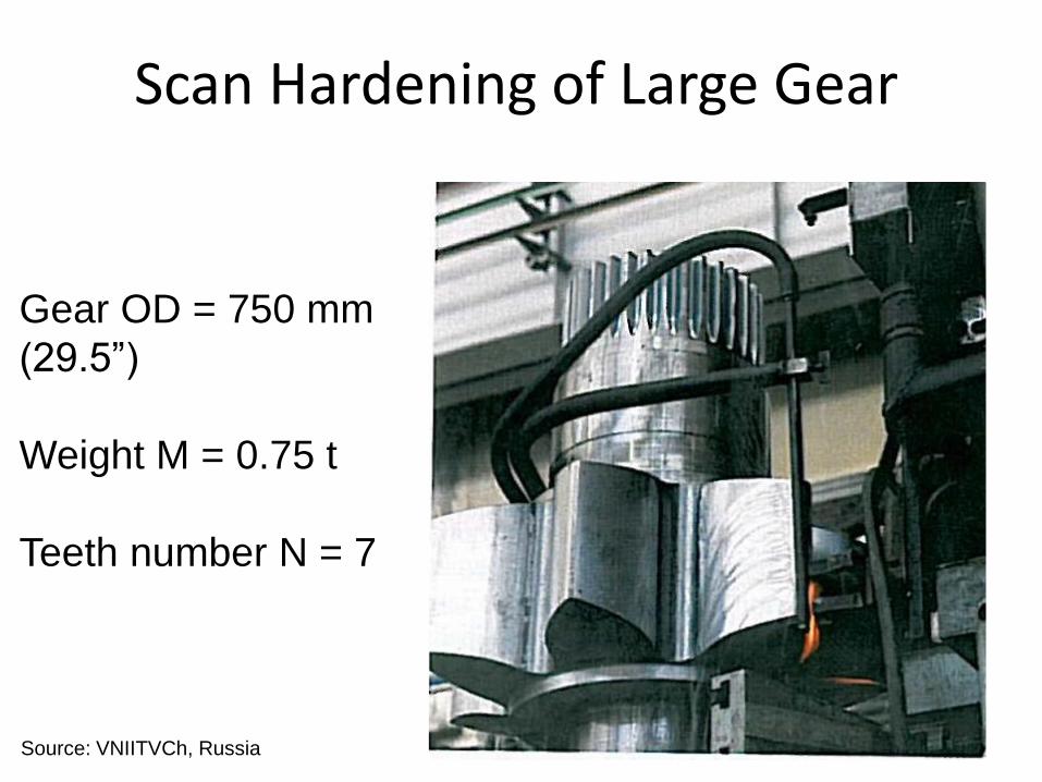
Scan Hardening of Large Gear
Gear OD = 750 mm
(29.5”)
Weight M = 0.75 t
Teeth number N = 7
Source: VNIITVCh, Russia

Other Methods
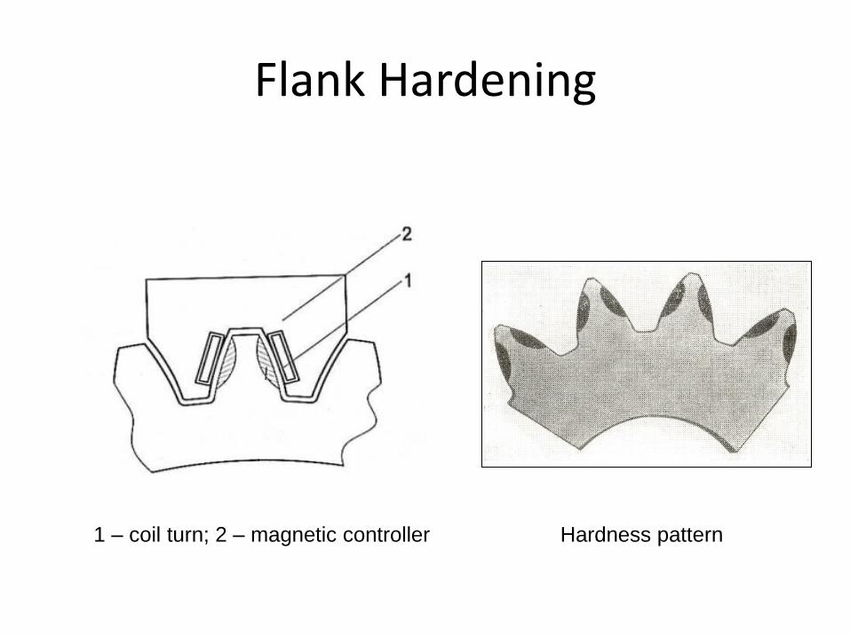
Flank Hardening
1 – coil turn; 2 – magnetic controller Hardness pattern
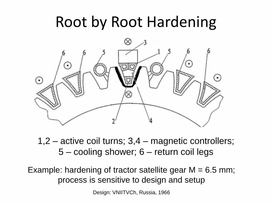
Root by Root Hardening
1,2 – active coil turns; 3,4 – magnetic controllers;
5 – cooling shower; 6 – return coil legs
Example: hardening of tractor satellite gear M = 6.5 mm;
process is sensitive to design and setup
Design: VNIITVCh, Russia, 1966
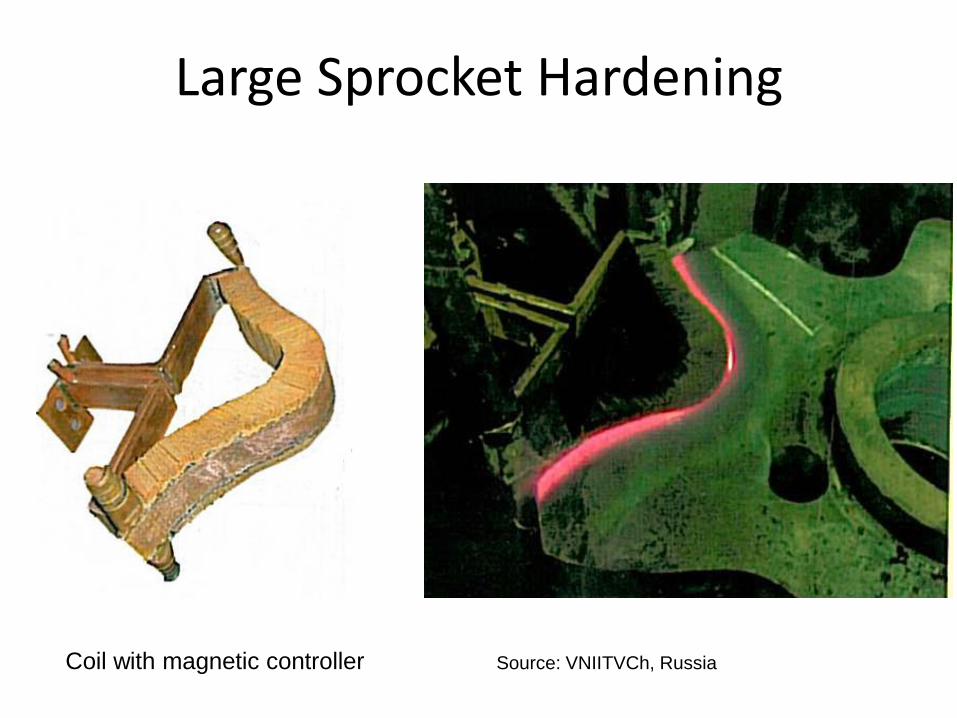
Large Sprocket Hardening
Source: VNIITVCh, Russia Coil with magnetic controller
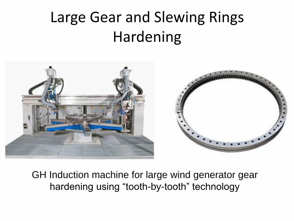
Large Gear and Slewing Rings Hardening
GH Induction machine for large wind generator gear
hardening using “tooth-by-tooth” technology
Using Steels with Controlled Hardenability
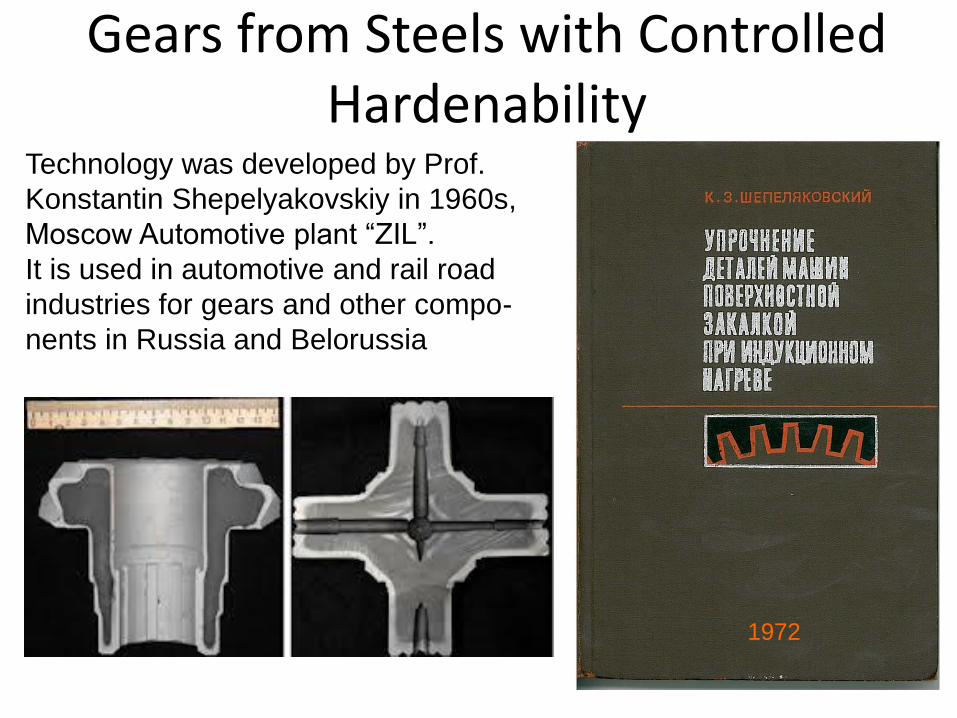
Gears from Steels with Controlled Hardenability
Technology was developed by Prof.
Konstantin Shepelyakovskiy in 1960s,
Moscow Automotive plant “ZIL”.
It is used in automotive and rail road
industries for gears and other compo-
nents in Russia and Belorussia
1972
2
3
1
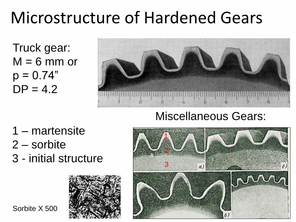
Microstructure of Hardened Gears
1 – martensite
2 – sorbite
3 - initial structure
Miscellaneous Gears:
Sorbite X 500
Truck gear:
M = 6 mm or
p = 0.74”
DP = 4.2
Special Features of the Method
Source: Prof. K. Shepelyakovskiy
• Low alloyed steels made according to a special
technology
• Deep induction or even furnace heating may be
used
• Very intensive water quenching is required to
achieve optimal results
• Sorbite layer formation under the martensite layer
improves gear performance
• Method is low sensitive to heating process

Computer Simulation
Simulation of Gear Hardening
Computer simulation of induction gear hardening is one of the most
difficult tasks of induction heating due to:
- 3D nature geometry of the system
- Strong coupling of Electromagnetic and Thermal phenomena
- High frequency and large gradients of magnetic and thermal fields
require fine meshing
- Frequency variation or application of two different frequencies (in
the case of SDF heating)
- System geometry variation in the case of scan hardening (at the
extremities of the gear)
In spite of these difficulties at present time we have successful
examples of computer simulation of Electromagnetic, Thermal and
Structural phenomena and even Stress and Distortion distributions.
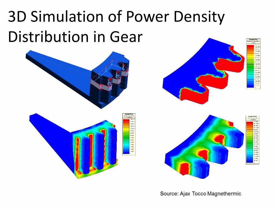
3D Simulation of Power Density Distribution in Gear
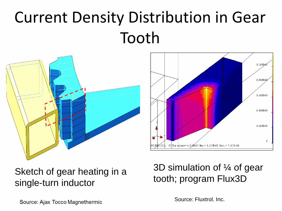
3D simulation of ¼ of gear
tooth; program Flux3D Sketch of gear heating in a
single-turn inductor
Current Density Distribution in Gear Tooth
Source: Fluxtrol. Inc.
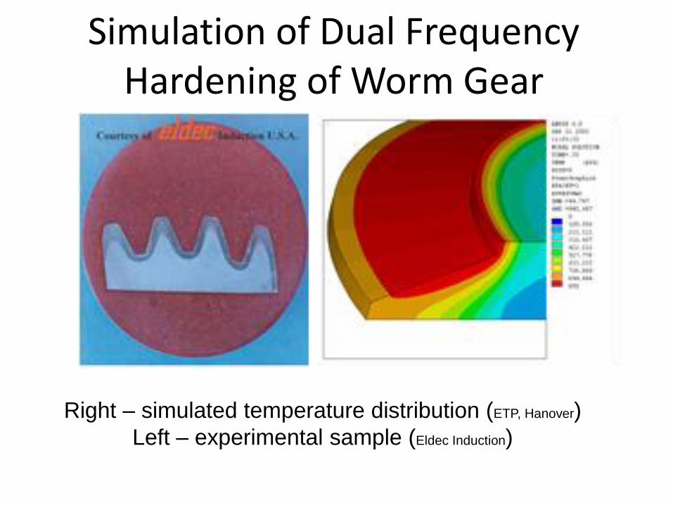
Simulation of Dual Frequency Hardening of Worm Gear
Right – simulated temperature distribution (ETP, Hanover)
Left – experimental sample (Eldec Induction)
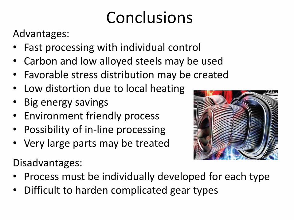
Conclusions Advantages: • Fast processing with individual control • Carbon and low alloyed steels may be used • Favorable stress distribution may be created • Low distortion due to local heating • Big energy savings • Environment friendly process • Possibility of in-line processing • Very large parts may be treated
Disadvantages: • Process must be individually developed for each type • Difficult to harden complicated gear types
Quote
“I have been amazed at the testing results of
the components that have broken many of the
established rules of structure, carbon level,
hardness, etc., of the component attributes” –
Dick Collins, Borg Warner Automotive, talking
about induction hardened parts
1388 Atlantic Blvd, Auburn Hills, MI, 48326, ph. +1 248 393 2000, www.fluxtrol.com