induction generator€¦ · no control of the reactive power. note that the synchronous concept of...
TRANSCRIPT
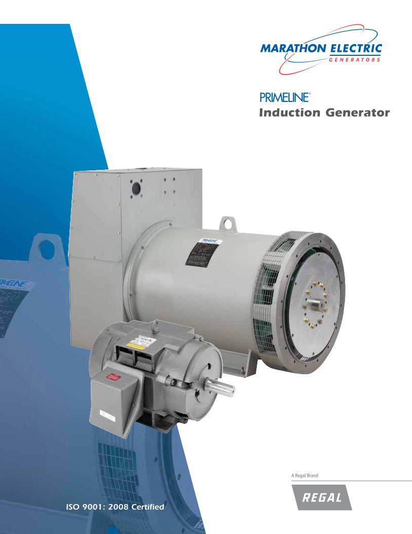
Induction Generator
A Regal Brand
ISO 9001: 2008 Certified

2
General Description Of ProductThe PrimeLine® induction generator is a rotating induction machine whose electrical per-formance has been designed to optimize its performance as a generator. The drip-proof frame construction used throughout is as follows:
nemA Two Bearing Units:250 to 320 frame – rolled steel frame with cast iron end brackets.360 to 510 frame – all cast iron construction.
Single Bearing Units:360 frame – all cast iron construction.430 & 570 frame – rolled steel frame with cast iron end brackets.
430 and 570 frame single bear-ing units are in the same mount-ing dimension as marathon’s mAgnAPLUS® and mAgnAmAx® synchronous offering to provide customers with interchangeabil-ity and allow for one common rail design.
All rotors are of rugged construc-tion. regreasable double shielded ball bearings are used through-out. A torsionally engineered SAe engine coupling system is avail-able for a portion of the product which is used in engine driven applications.
The listings described in this brochure are basic standard ratings. There will always be applications that will require specific design. Contact factory for your special requirements.
Generator BasicsThe induction generator is similar to any other generator, as it is a device that converts mechanical energy into electrical energy.
An induction generator consists of a rotating element or rotor and a stationary element or stator. The rotor consists of an aluminum or copper ‘squirrel cage’ within the rotor laminations. The statorconsists of insulated copper wind-ings within the stator laminations. neither an exciter nor voltage reg-ulator is used or required.
An induction machine (motor or generator) connected to the line power source (excitation) is capable of operating in either mode. if the shaft is allowed to rotate at a speed below synchronous, the machine will attempt to operate as a motor. The rotating magnetic field vector caused by the three phase stator windings will deliver real and reactive power to the rotor as it sweeps around the squir-rel cage. if the shaft is forced to rotate at a speed higher than syn-chronous, a change takes place within the machine. The stator magnetic field vector will continue to deliver reactive power, but now accepts real power induced from the rotor (generator mode). now the squirrel cage is sweeping the field vector, causing a flux reversal. At synchronous speed, the line supplies reactive power and machine losses, but no torque or power is generated.
There is a practical upper limit to the speed at which an induction generator can be operated above
synchronous and still generate real power efficiently. This speed is typically 2 to 5 percent above synchronous, but below break-away torque. Above the break-away torque speed, the real power generated decays quickly to a low value.
The induction generator and induction motor are in theory similar, but the PrimeLine® induction generator has significant differences from standard motors:
1. The emphasis on the PrimeLine® design is to maximize the efficiency with minimum reduction in power factor.2. Class F varnish is used in place of the class B varnish that is standard on motors.3. Additional felt and winding ties are used for coil support to withstand operating cond- tions that are not experienced by motors.
Induction Generator
1800
1825
1815
1805
1795
1785
3
ApplicationsThere are two types of alternating current generators in commercial use – the synchronous generator and the induction generator. The current role today for the induction generator is for those applications requiring the simplest, lowest total system cost means of converting excess or previously untapped ener-gy into electricity. An induction gen-erator cannot generate electricity in a stand-alone mode.
There are a number of marked dif-ferences between the application of synchronous generators and induc-tion generators. in most induction generator applications, power factor correction in the form of capacitance will be required to raise the induction generator’s operating power factor up to the area of 0.90 to 0.95 lagging. (Power factor correction information is available from companies that sup-ply industrial capacitor banks.) The kVA of capacitor correction applied should not exceed the no-load, or magnetizing kVA of the induction generator. excessive capacitance has the potential to cause the gen-erator to go into a self-exciting mode should the utility fail even momen-tarily. This self excited mode will typically have voltage and frequency deviations sufficient to cause dam-age to the generator, and perhaps even to the connected load.
When an engine driven synchronous generator is operated in parallel with a source much larger than itself, the throttle controls the real power (kilo-watts) generated and the voltage regulator controls the reactive power (kilovars) generated. The speed of the generator does not change over the controllable range. in an induc-tion generator, the throttle controls the real power generated; there is no control of the reactive power. note that the synchronous concept of parallel operation has no coun-terpart with induction operation. The frequency of the induction generator does not change over the controllable range from synchronous to perhaps 2 to 5 percent above synchronous speed. Changes in the bus voltage
by the utility source cause reactive power changes in the synchronous generator and real power changes in the induction generator.
When an induction generator or any driven load is connected to an engine, the torsional analysis must be performed on the connected system to assure that vibration resonances do not cause premature failure of any bearings or major drive change components.
The factors that are most critical to torsional vibration are contained in the design of the engine. The engine-generator set manufacturer, his representative, or buyer shall be responsible for the torsional analysis and approval of the engine-generator combination. marathon electric shall submit for approval, rotor weight and WK squared information, along with such other data as it deems neces-sary when approval has not already been obtained on a specific diesel-generator combination.
Generator ProtectionProtective devices that should be used in induction generator applica-tions include contactors, overload sensors and circuit breakers. These devices are applied with an induction generator in the same way as with a motor. Additional protection can be provided by the use of meters, over current sensors, voltage balance sensors, over/under voltage controls, and temperature detectors.
To prevent the induction generator from reaching the pushover point, overspeed protection should be placed on the prime mover. This protection can be in the form of governors, speed switches, etc.
reverse power relays are used to sense direction of power flow and to disconnect the induction genera-tor when it begins to operate as a motor. A reverse power relay is recom-mended for all applications.
All protective devices used must be coordinated throughout the complete system.
Advantages Over AC Synchronous GeneratorsWhen compared to a synchronous generator, the induction generator has several advantages: •No voltage regulator is required. Voltage and frequency are controlled by the utility. •Excitation is provided by the utility. •Simpleconstruction;nobrushes, diodes, or collector rings. •No synchronizing circuit for paralleling to the utility. •Lowermaintenancecosts. •Large power swings do not pull the generator out of synchronization with the system.
Application Considerations1. Three phase or single phase2. Voltage3. Synchronous rPm4. maximum kW output at a specified temperature rise.5. Prime mover (engine or turbine) characteristics6. Ambient temperature7. Altitude8. Will the unit ever be operated as a motor?9. Coordinate with the utility for capacity to supply the excitation required by the induction generator10. Will the machine be subjected to adverse environmental conditions?11. Dripproof construction12. Special full load speed requirements13. Special efficiency and/or power factor14. Special temperature rise requirements15. Special shaft requirements16. Flange mounting17. Direct drive or belted (if belted, furnish complete drive details)18. Thrust load (which direction?)19. is engineering information required for torsional approval?20. Other special electrical or mechanical requirements21. induction generator cannot supply reactive power for motor starting?
4
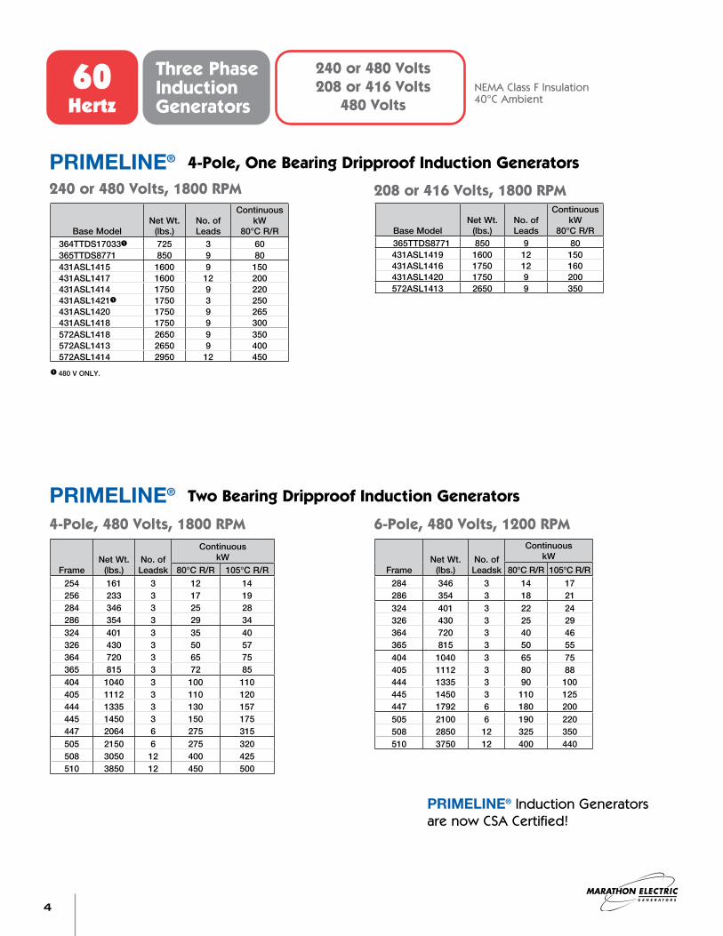
60 Hertz
Three PhaseInduction Generators
240 or 480 Volts208 or 416 Volts
480 VoltsNEMA Class F Insulation40°C Ambient
4-Pole, One Bearing Dripproof Induction GeneratorsPRIMELINE®
Two Bearing Dripproof Induction GeneratorsPRIMELINE®
240 or 480 Volts, 1800 RPM 208 or 416 Volts, 1800 RPM
4-Pole, 480 Volts, 1800 RPM 6-Pole, 480 Volts, 1200 RPM
PRIMELINE® Induction Generators are now CSA Certified!
Base modelnet Wt.
(lbs.)no. of Leads
Continuous kW
80°C r/r364TTDS170331 725 3 60365TTDS8771 850 9 80431ASL1415 1600 9 150431ASL1417 1600 12 200431ASL1414 1750 9 220431ASL14211 1750 3 250431ASL1420 1750 9 265431ASL1418 1750 9 300572ASL1418 2650 9 350572ASL1413 2650 9 400572ASL1414 2950 12 450
Base modelnet Wt.
(lbs.)no. of Leads
Continuous kW
80°C r/r365TTDS8771 850 9 80431ASL1419 1600 12 150431ASL1416 1750 12 160431ASL1420 1750 9 200572ASL1413 2650 9 350
Framenet Wt.
(lbs.)no. of Leadsk
Continuous kW
80°C r/r 105°C r/r254 161 3 12 14256 233 3 17 19284 346 3 25 28286 354 3 29 34324 401 3 35 40326 430 3 50 57364 720 3 65 75365 815 3 72 85404 1040 3 100 110405 1112 3 110 120444 1335 3 130 157445 1450 3 150 175447 2064 6 275 315505 2150 6 275 320508 3050 12 400 425510 3850 12 450 500
Framenet Wt.
(lbs.)no. of Leadsk
Continuous kW
80°C r/r 105°C r/r284 346 3 14 17286 354 3 18 21324 401 3 22 24326 430 3 25 29364 720 3 40 46365 815 3 50 55404 1040 3 65 75405 1112 3 80 88444 1335 3 90 100445 1450 3 110 125447 1792 6 180 200505 2100 6 190 220508 2850 12 325 350510 3750 12 400 440
1 480 V OnLY.
5
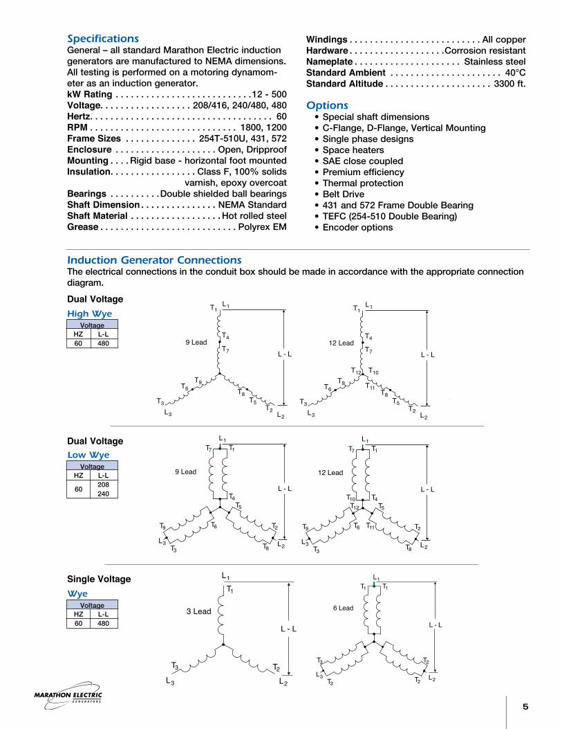
Induction Generator ConnectionsThe electrical connections in the conduit box should be made in accordance with the appropriate connection diagram.
High WyeVoltage
HZ L-L 60 480
Dual Voltage
Dual Voltage
Single VoltageWye
Voltage HZ L-L 60 480
Specificationsgeneral – all standard marathon electric induction generators are manufactured to nemA dimensions. All testing is performed on a motoring dynamom-eter as an induction generator.kW Rating . . . . . . . . . . . . . . . . . . . . . . . . . . .12 - 500Voltage. . . . . . . . . . . . . . . . . . 208/416, 240/480, 480Hertz. . . . . . . . . . . . . . . . . . . . . . . . . . . . . . . . . . . . 60RPM . . . . . . . . . . . . . . . . . . . . . . . . . . . . . 1800, 1200Frame Sizes . . . . . . . . . . . . . . 254T-510U, 431, 572Enclosure . . . . . . . . . . . . . . . . . . . . Open, DripproofMounting . . . . rigid base - horizontal foot mountedInsulation. . . . . . . . . . . . . . . . . Class F, 100% solids varnish, epoxy overcoatBearings . . . . . . . . . .Double shielded ball bearingsShaft Dimension . . . . . . . . . . . . . . . nemA StandardShaft Material . . . . . . . . . . . . . . . . . . Hot rolled steelGrease . . . . . . . . . . . . . . . . . . . . . . . . . . . Polyrex em
Windings . . . . . . . . . . . . . . . . . . . . . . . . . . All copperHardware . . . . . . . . . . . . . . . . . . .Corrosion resistantNameplate . . . . . . . . . . . . . . . . . . . . . Stainless steelStandard Ambient . . . . . . . . . . . . . . . . . . . . . . 40°CStandard Altitude . . . . . . . . . . . . . . . . . . . . . 3300 ft.
Options •Specialshaftdimensions •C-Flange,D-Flange,VerticalMounting •Singlephasedesigns •Spaceheaters •SAEclosecoupled •Premiumefficiency •Thermalprotection •BeltDrive •431and572FrameDoubleBearing •TEFC(254-510DoubleBearing) •Encoderoptions
Low WyeVoltage
HZ L-L 60 208 240
L - L
L1
L2L3
T1
T4
T7
T3
T6T9
T12 T10
T11T8
T2
T5
12 Lead
L - L0
L - L
L1
L2L3
T1
T4
T7
T3
T6T9
T0
T8
T2
T5
10 Lead
L1T7 T1
T10T5
T2
T8
T11T6
T3
T9
T12
T4
L - L
L3 L2
12 Lead
L1
T1
T2T3
L - L
L3 L2
3 Lead
L1T7 T1
T0 T5
T2
T8
T6
T3
T9
T4
L - L
L - L0L3 L2
10 Lead
L1T1 T1
T2
T2T3
T3
L - L
L3 L2
6 Lead
L1T7 T1
T5
T2
T8
T6
T3
T9
T4
L - L
L3 L2
9 Lead
L - L
L1
L2L3
T1
T4
T7
T3
T6T9
T8
T2
T5
9 Lead L - L
L1
L2L3
T1
T4
T7
T3
T6T9
T12 T10
T11T8
T2
T5
12 Lead
L - L0
L - L
L1
L2L3
T1
T4
T7
T3
T6T9
T0
T8
T2
T5
10 Lead
L1T7 T1
T10T5
T2
T8
T11T6
T3
T9
T12
T4
L - L
L3 L2
12 Lead
L1
T1
T2T3
L - L
L3 L2
3 Lead
L1T7 T1
T0 T5
T2
T8
T6
T3
T9
T4
L - L
L - L0L3 L2
10 Lead
L1T1 T1
T2
T2T3
T3
L - L
L3 L2
6 Lead
L1T7 T1
T5
T2
T8
T6
T3
T9
T4
L - L
L3 L2
9 Lead
L - L
L1
L2L3
T1
T4
T7
T3
T6T9
T8
T2
T5
9 Lead
L - L
L1
L2L3
T1
T4
T7
T3
T6T9
T12 T10
T11T8
T2
T5
12 Lead
L - L0
L - L
L1
L2L3
T1
T4
T7
T3
T6T9
T0
T8
T2
T5
10 Lead
L1T7 T1
T10T5
T2
T8
T11T6
T3
T9
T12
T4
L - L
L3 L2
12 Lead
L1
T1
T2T3
L - L
L3 L2
3 Lead
L1T7 T1
T0 T5
T2
T8
T6
T3
T9
T4
L - L
L - L0L3 L2
10 Lead
L1T1 T1
T2
T2T3
T3
L - L
L3 L2
6 Lead
L1T7 T1
T5
T2
T8
T6
T3
T9
T4
L - L
L3 L2
9 Lead
L - L
L1
L2L3
T1
T4
T7
T3
T6T9
T8
T2
T5
9 Lead

6
Standard Two Bearing Mounting
KEY
BSBA
AC
AB
LEAD HOLEAA
U
P
O
N-W
4 HOLES'H' DIA.2F E
-.06+.00D
C
B A
KEYOH2FEDCBAFRAME AB ACN-W P AAU BA BS
.88x.88x5.0012.5025.00510US 34.50 55.50 10.00 32.00 6.75 3.37516.004.12511.6232.0010.0060.3834.50510U 25.00 12.50 1.00x1.00x9.00
3.3756.7525.0010.0048.5027.50508US 25.00 12.50 .88x.88x5.0012.504.125 6.6227.1211.62 19.8126.3829.6225.0010.0053.3827.50508U 25.00 12.50 1.00x1.00x9.00
2.3754.7518.0010.0039.5020.50505US 25.00 12.50 .62x.62x3.259.003.87527.0010.12 17.6222.1229.50.9418.0010.0044.8820.50505U 25.00 12.50 1.00x1.00x9.00
2.3754.75 19.1925.8125.009.0044.5027.50449TS 21.75 11.00 .62x.62x3.0012.503.3758.50 17.0021.4425.009.0048.2527.50449T 21.75 11.00 .88x.88x6.88
2.3754.75 19.1925.8120.009.0039.5022.50447TS 21.75 11.00 .62x.62x3.0010.003.375 4.6224.258.50 17.0021.4425.5020.009.0043.2522.50447T 21.75 11.00 .88x.88x6.88
2.3754.7516.509.0036.0019.00445TS 21.75 11.00 .62x.62x3.008.253.3758.5016.509.0039.7519.00445T 21.75 11.00 .88x.88x6.88
2.3754.7514.509.0034.0017.00444TS 21.75 11.00 .62x.62x3.007.257.503.37522.508.50 14.6219.8825.5014.509.0037.7517.00444T 21.75 11.00 .88x.88x6.88
2.1254.2513.758.0031.0017.00405TS 19.75 10.00 .50x.50x2.756.882.8757.2513.758.0034.0016.50405T 19.75 10.00 .75x.75x5.62
2.1254.2512.258.0029.5016.50404TS 19.75 10.00 .50x.50x2.756.622.875 4.1220.627.25 13.6919.0023.50.8112.258.0032.5015.00404T 19.75 10.00 .75x.75x5.62
1.8753.7512.257.0027.5015.00365TS 17.75 9.00 .50x.50x2.006.122.3755.8812.257.0029.6214.25365T 17.75 9.00 .62x.62x4.25
1.8753.7511.257.0026.5014.25364TS 17.75 9.00 .50x.50x2.005.625.882.375 3.6218.625.88 12.1916.3821.5011.257.0028.6213.25364T 17.75 9.00 .62x.62x4.25
1.8753.7512.006.2526.0013.25326TS 14.62 8.00 .50x.50x2.006.002.1255.2512.006.2527.5013.25326T 14.62 8.00 .50x.50x3.88
1.8753.7510.506.2524.5013.00324TS 14.62 8.00 .50x.50x2.005.255.252.125 2.0014.625.25 9.6912.6918.06.6610.506.2526.0013.00324T 14.62 8.00 .50x.50x3.88
1.6253.2511.005.5023.5613.25286TS 13.00 7.00 .50x.50x1.885.501.8754.6211.005.5024.9913.25286T 13.00 7.00 .50x.50x3.25
1.6253.259.505.5022.0611.75284TS 13.00 7.00 .50x.50x1.884.754.751.875 1.5012.884.62 8.7511.7516.319.505.5023.4911.75284T 13.00 7.00 .50x.50x3.259.4310.005.0022.3211.24256T 10.38 6.257.694.251.625 1.759.504.00 6.6512.03.538.255.0020.5711.24254T 10.38 6.25 .38x.38x2.888.15
.38x.38x2.88
4.75
5.50
5.25
6.00
5.62
6.12
6.88
7.25
8.25
10.00
12.50
9.00
12.50
16.00
6.126.12
4.25
4.75
5.25
5.88
6.62
7.50
4.75
5.25
5.88
6.62
7.50
4.75
5.25
5.88
6.62
7.507.507.507.507.507.507.507.507.507.507.50
6.65
8.75
9.69
12.19
13.69
14.62
17.62
19.81
8.75
9.69
12.19
13.69
14.62
19.81
8.75
9.69
12.19
13.69
14.62
19.81
8.15
11.75
12.69
16.38
19.00
19.88
22.12
26.38
11.75
12.69
16.38
19.00
19.88
26.38
11.75
12.69
16.38
19.00
19.88
26.38
1.75
1.50
2.00
3.62
4.12
4.62
6.62
1.625
27.12
27.00
29.62
29.50
25.50 24.25
22.5025.50
23.50 20.62
21.50 18.62
18.06 14.62
12.8816.31
12.03 9.50.53 4.00
.66
.81
.94
1.50
2.00
3.62
4.12
4.62
6.62
1.50
2.00
3.62
4.12
4.62
6.62
4.12
4.62
4.12
4.62
4.124.12
.53
.53
.53
.5316.31 12.8816.31 12.88
.66
.66
.66
.66
.66
.66
.81
.81
.81
.81
.81
.81
.81
.81
.81
.81
.94
.94
.94
.9429.62 27.1229.62 27.12
25.50 24.25
25.50 22.50
23.50 20.62
25.50 24.25
25.50 22.50
23.50 20.62
21.50 18.6221.50 18.62
18.06 14.6218.06 14.62
Induction Generator
All dimensions are approximate.Certified prints available on request.For reference only, not for construction .

7
Standard Single Bearing Mounting
Induction Generator
BS
(B)
2F7.00
.38
(.38)
(C)
.22
(.88)
(23.01)
9.008.94
(17.76)
14.00
7.00
(.97)
(Ø22.50)
(2.88)
�.66.71 2 SLOTS
(11.75)
Ø.66-712 HOLES
2 SLOTS THIS ENDSEE DETAIL
(3.38)
(4.00)
Ø3.62 LEAD HOLE
(12.69)
(16.23)
(27.48)
5.75
365T 14.25
FRAME
364T 13.25
B
6.125.62
12.2524.5011.25
C
23.50
2F BS
Frame 364T/365T
(8.00)10.00
(39.75)
(17.96)
22.62 MAX.FR. DIA.
11.00(15.00)
6.00
(16.00)(2.79)
R14.25
9.00
18.00
(21.49)
13.0012.94
(.38)
(24.97).25
(.88)
(12.49)
DRIPCOVER (OPTIONAL)
AUX. TERMINALBOX (OPTIONAL)
36.10
Frame 431
All dimensions are approximate.Certified prints available on request.For reference only, not for construction .
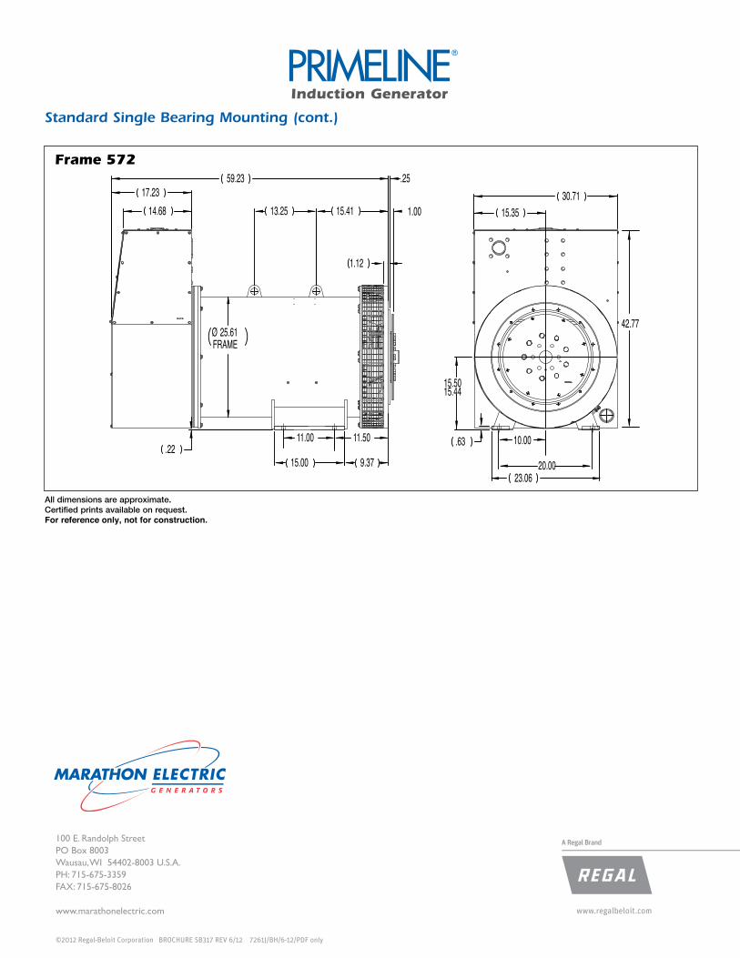
.22
Ø 25.61FRAME
13.25
59.23
15.00 9.37
1.12
1.00
.25
15.4114.6817.23
23.06
.63
15.5015.44
20.00
15.3530.71
11.00 11.50 10.00
42.77
Frame 572
Standard Single Bearing Mounting (cont.)
Induction Generator
All dimensions are approximate.Certified prints available on request.For reference only, not for construction .
A Regal Brand100 E. Randolph StreetPO Box 8003Wausau, WI 54402-8003 U.S.A.PH: 715-675-3359FAX: 715-675-8026
www.marathonelectric.com
©2012 Regal-Beloit Corporation BROCHURE SB317 REV 6/12 7261J/BH/6-12/PDF only