indoor cycle owner’s manual -...
TRANSCRIPT

INDOOR CYCLE OWNER’S MANUAL
LS9.9IC

2

3
IMPORTANT PRECAUTIONSSAVE THESE INSTRUCTIONS
When using an exercise product, basic precautions should always be followed, including the following: Read all instructions before using this indoor cycle. It is the responsibility of the owner to ensure that all users of this indoor cycle are adequately informed of all warnings and precautions. If you have any questions after reading this owner’s manual, contact Customer Tech Support at the number listed on the back panel.

4
READ AND SAVE ALL INSTRUCTIONS bEfORE ASSEmbLINg OR USINg THIS INDOOR CyCLE. IT IS STRONgLy RECOmmENDED TO TAkE THE fOLLOwINg SAfETy INSTRUCTIONS.
• CAUTION: If you experience chest pains, nausea, dizziness or shortness of breath, stop exercising immediately and consult your physician before continuing.
• Use this cycle for its intended purpose as described in this manual. Do not use attachments that have not been recommended by the manufacturer.
• Never operate the cycle if it is not working properly, or if it has been damaged. Contact Livestrong Fitness or the authorized dealers for examination and repair.
• Do not use the cycle without proper footwear. NEVER operate the cycle with bare feet. • Do not wear any clothing that might catch on any moving parts of this cycle. • Keep hands and feet clear at all times from moving parts to avoid injury. Never turn the pedal cranks by hand. • Do not dismount the cycle until the pedals are at a complete STOP. • Do not attempt to ride the cycle in a standing position at high RPMs until you have practiced at slower speeds. • Do not insert any object, hands or feet into any openings, or expose hands, arms or feet to the drive mechanism or other potentially
moving part of the cycle. • Do not use any equipment that is damaged or has worn or broken parts. Use only replacement parts supplied by Livestrong Fitness or
the authorized dealers. • Do not operate where aerosol (spray) products are being used or when oxygen is being administered. • Close supervision is necessary when used near children, invalids or disabled people. • When the cycle is in use, young children and pets should be kept at least 3 meters / 10 feet away. • After exercising, push down on the tension knob or turn the tension knob in a clockwise direction to slow the flywheel down and
decrease the potential for injury. • Ensure that adjustment levelers (seat and handlebar height, seat and handlebar fore-and-aft) are properly secured and do not interfere
with range of motion during exercise. • It is the sole responsibility of the owner to ensure that all users of the indoor cycle are informed of all warnings and precautions. • Keep the indoor cycle indoors, away from moisture and dust. Do not place the indoor cycle in a garage, covered patio or near water. • Place the indoor cycle on a level surface to protect the floor or carpet from damage, place a mat beneath the indoor cycle. • The indoor cycle does not have a independently moving flywheel; the pedals will continue to move together with the flywheel until the
flywheel stops.
wARNINg

5
ASSEMBLY
There are several areas during the assembly process that special attention must be paid. It is very important to follow the assembly instructions correctly and to make sure all parts are firmly tightened. If the assembly instructions are not followed correctly, the indoor cycle could have parts that are not tightened and will seem loose and may cause irritating noises. To prevent damage to the indoor cycle, the assembly instructions must be reviewed and corrective actions should be taken.
Before proceeding, find your indoor cycle’s serial number located on the lower front of the cycle and enter it in the space provided below.
ENTER YOUR SERIAL NUMBER IN THE BOX BELOW:
» Refer to the SERIAL NUMBER and MODEL NAME when calling for service.» Be sure to enter both the SERIAL NUMBER and MODEL NAME on your warranty card.
SERIAL NUMBER:
MODEL NAME: HORIzON LS9.9IC INDOOR CyCLE
wARNINg

6
TOOLS NEEDED fOR ASSEmbLy:
F Wrench: 17/19mm, 13/15mm, F Allen Wrench: 3mm, 6mm
If you have questions or if there are any missing parts, contact Customer Tech Support. Contact information is located on the back panel of this manual.
UNPACkINg
Due to the weight of the indoor cycle, it is recommended that two persons perform the assembly. Set the studio cycle in a cleared area and remove all packing materials; do not dispose of the packing materials until assembly is completed NOTE: During each assembly step, ensure that ALL nuts and bolts are in place and partially threaded in before completely tightening any ONE bolt. NOTE: A light application of grease may aid in the installation of hardware. Any grease, such as lithium bike grease is recommended.
NEED HELP?
PRE ASSEMBLY
Computer ConsoleEmergency Brake & Resistance Knob
HandlebarSaddle
Adjustment Knob
Pedal
Belt Guard
Maintenance Cover
Levelling Feet Transport Wheel
Flywheel
Brake Pad
Adjustment Knob
LS9.9IC PARTS INCLUDED

7
ASSEMBLY STEP 1 & 2
A Identify the Rear Stabilizer. While a second person lifts the rear of the frame, attach the Rear Stabilizer to the Frame with two M10 x 60mm Bolts, four M10 Washers, a Stabilizer Gasket, two Plastic Washers, and two M10 Cap Nuts as shown.
B Support the Front Stabilizer while a second person lifts the front of the Frame. Attach the Front Stabilizer to the Frame with two M10 x 60mm Bolts, four M10 Washers, a Stabilizer Gasket, two Plastic Washers and two M10 Cap Nuts.

8
ASSEMBLY STEP 3 & 4
A Turn the rear Adjustment Knob counter clockwise and pull the adjustment knob to insert the Saddle Post into the Frame. Next, bring the Saddle Post to the desired height, release the adjustment knob so the pin engages into the holes of the saddle post. Then turn the Adjustment Knob clockwise to retighten until it is snug.
B Mount saddle to the horizontal saddle post as shown above. Finally, firmly retighten the saddle mounting clamp and make sure that the saddle is mounted in its most horizontal position at the middle of the rail.
C To adjust the horizontal saddle position, turn the small adjustment knob counter clockwise to adjust desired horizontal saddle position and retighten until it is snug.
D Please don’t adjust the height of the vertical saddle support beyond the stop mark to avoid instability.
STOP mARk
9
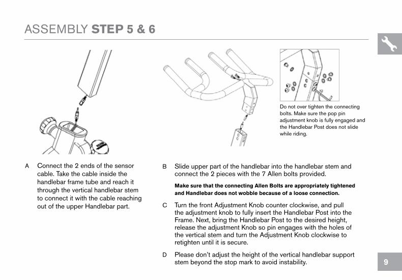
ASSEMBLY STEP 5 & 6
A Connect the 2 ends of the sensor cable. Take the cable inside the handlebar frame tube and reach it through the vertical handlebar stem to connect it with the cable reaching out of the upper Handlebar part.
B Slide upper part of the handlebar into the handlebar stem and connect the 2 pieces with the 7 Allen bolts provided. make sure that the connecting Allen bolts are appropriately tightened and Handlebar does not wobble because of a loose connection.
C Turn the front Adjustment Knob counter clockwise, and pull the adjustment knob to fully insert the Handlebar Post into the Frame. Next, bring the Handlebar Post to the desired height, release the adjustment Knob so pin engages with the holes of the vertical stem and turn the Adjustment Knob clockwise to retighten until it is secure.
D Please don’t adjust the height of the vertical handlebar support stem beyond the stop mark to avoid instability.
Do not over tighten the connecting bolts. Make sure the pop pin adjustment knob is fully engaged and the Handlebar Post does not slide while riding.

10
ASSEMBLY STEP 7 & 8
A Mount the computer console the handlebar by sliding it onto the bracket.
B Connect the 2 cables reaching out of the handlebar to the appropriate sockets on the bottom side of the computer console. Connect the cable with the red marking with the red marked socket. The other, none marked black cable with the other socket.
11
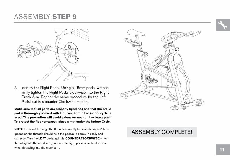
ASSEMBLY STEP 9
A Identify the Right Pedal. Using a 15mm pedal wrench, firmly tighten the Right Pedal clockwise into the Right Crank Arm. Repeat the same procedure for the Left Pedal but in a counter Clockwise motion.
make sure that all parts are properly tightened and that the brake pad is thoroughly soaked with lubricant before the indoor cycle is used. This precaution will avoid extensive wear on the brake pad. To protect the floor or carpet, place a mat under the Indoor Cycle.
NOTE: Be careful to align the threads correctly to avoid damage. A little
grease on the threads should help the pedals to screw in easily and
correctly. Turn the LEfT pedal spindle COUNTERCLOCkwISE when
threading into the crank arm, and turn the right pedal spindle clockwise
when threading into the crank arm.
ASSEMBLY COMPLETE!

12
INDOOR CYCLE OPERATION LS9.9IC SPECIfICATIONS
TECHNICAL DATA
SPECIAL FEATURES
*specifications are subject to change without notice.
Frame
Resistance Technology
Resistance Levels
Drive System
Flywheel
Handlebar Adjustments
Seat Adjustments
Dimensions (LxWxH)
Product Weight
Max User Weight
Handlebar Design
Crank
Pedals
Seat
Seat Post & Handlebar Stem
Water Bottle Cage
High-tensile, corrosion-resistant frame
Friction brake with microadjust knob and emergency stop
Infinitely variable with linear increase throughout resistance range
Hyper smooth chain wheel system
20 kg / 44 lbs.
Vertical & Horizontal
Vertical & Horizontal
106×54×103 cm / 42” ×21” ×41”
54 kg / 119 lbs.
159 kg / 350 lbs
Multi-position
Forging steel cranks
Fit-in-with pedals with adjustable strip
Comfortable Saddle
Rust-resistant Treatment
Yes

13
HOw TO ADjUST THE INDOOR CyCLE
The Indoor Cycle can be adjusted for maximum comfort and exercise effectiveness. The instructions below describe one approach to adjusting the Indoor Cycle to ensure optimal user comfort and ideal body positioning; you may choose to adjust the Indoor Cycle differently.
PEDAL STRAP ADjUSTmENT
Please do not adjust saddle height beyond the stop mark on the stem.
Please do not adjust the handlebar height beyond the stop mark on the stem
14
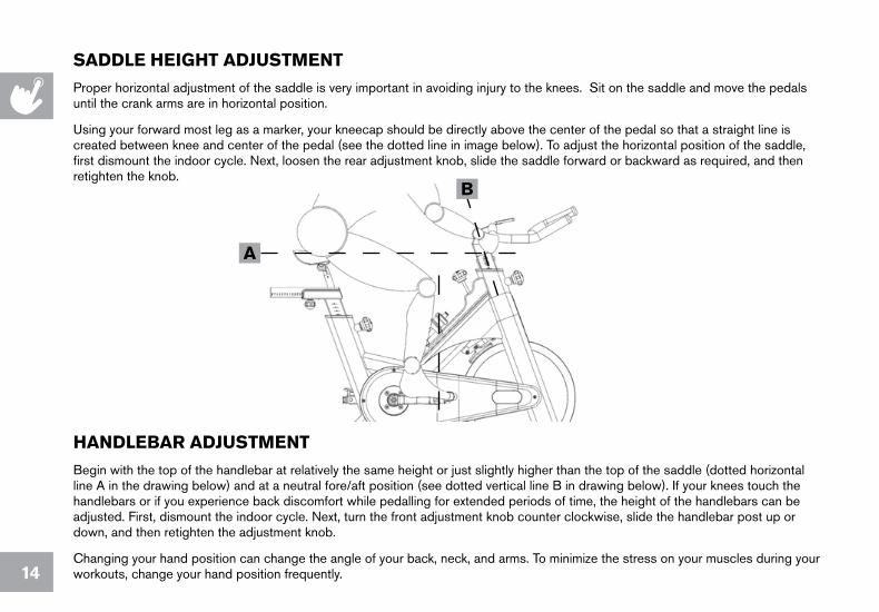
SADDLE HEIgHT ADjUSTmENT
Proper horizontal adjustment of the saddle is very important in avoiding injury to the knees. Sit on the saddle and move the pedals until the crank arms are in horizontal position.
Using your forward most leg as a marker, your kneecap should be directly above the center of the pedal so that a straight line is created between knee and center of the pedal (see the dotted line in image below). To adjust the horizontal position of the saddle, first dismount the indoor cycle. Next, loosen the rear adjustment knob, slide the saddle forward or backward as required, and then retighten the knob.
HANDLEbAR ADjUSTmENT
Begin with the top of the handlebar at relatively the same height or just slightly higher than the top of the saddle (dotted horizontal line A in the drawing below) and at a neutral fore/aft position (see dotted vertical line B in drawing below). If your knees touch the handlebars or if you experience back discomfort while pedalling for extended periods of time, the height of the handlebars can be adjusted. First, dismount the indoor cycle. Next, turn the front adjustment knob counter clockwise, slide the handlebar post up or down, and then retighten the adjustment knob.
Changing your hand position can change the angle of your back, neck, and arms. To minimize the stress on your muscles during your workouts, change your hand position frequently.
A
b
15
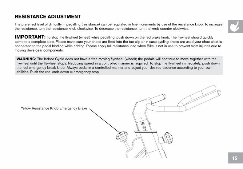
RESISTANCE ADjUSTmENT
The preferred level of difficulty in pedalling (resistance) can be regulated in fine increments by use of the resistance knob. To increase the resistance, turn the resistance knob clockwise. To decrease the resistance, turn the knob counter clockwise.
ImPORTANT: To stop the flywheel (wheel) while pedalling, push down on the red brake knob. The flywheel should quickly come to a complete stop. Please make sure your shoes are fixed into the toe clip or in case cycling shoes are used your shoe cleat is connected to the pedal binding while ridding. Please apply full resistance load when Bike is not in use to prevent from injuries due to moving drive gear components.
wARNINg: The Indoor Cycle does not have a free moving flywheel (wheel); the pedals will continue to move together with the flywheel until the flywheel stops. Reducing speed in a controlled manner is required. To stop the flywheel immediately, push down the red emergency break knob. Always pedal in a controlled manner and adjust your desired cadence according to your own abilities. Push the red knob down = emergency stop
Yellow Resistance Knob Emergency Brake

16
HOw TO mOVE THE INDOOR CyCLE
Due to the weight of the Indoor Cycle, it is recommended that two persons move it. While one person lifts the back of the indoor cycle, the second person firmly holds the handlebar and tips the indoor cycle forward until it rolls on the wheels. Carefully move the Indoor Cycle to the desired location and then lower it. CAUTION: To reduce the risk of injury, use extreme caution while moving the indoor studio cycle. Do not attempt to move it over uneven surfaces and make sure there’s a safety space of 20 inch (minimum) to the nearest equipment is (recommended).
If the Indoor Cycle rocks on the floor after being set down, turn the levelling feet underneath the front or rear stabilizer until the rocking motion is eliminated. Important: Please do not unscrew the levelling feet more than ½ inch !
Leveling Feet
17
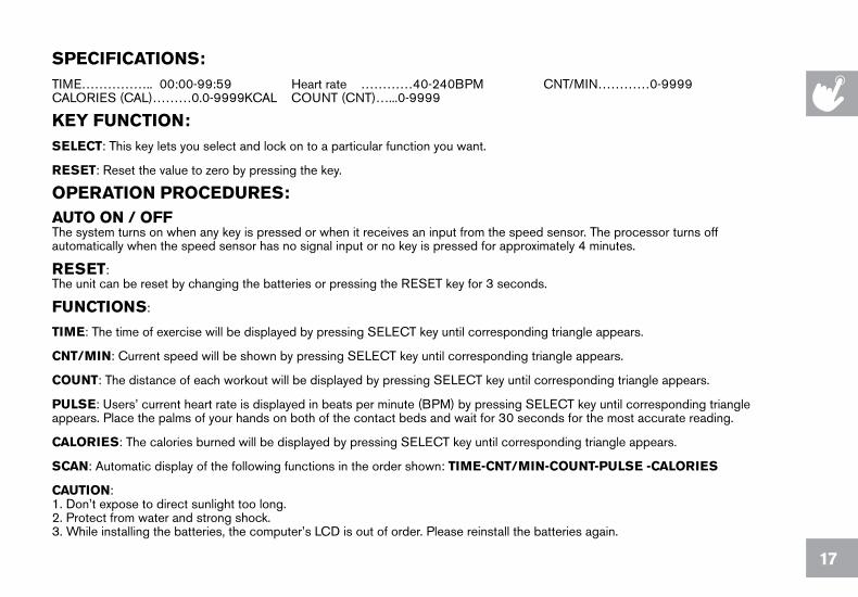
SPECIfICATIONS:TIME…………….. 00:00-99:59 Heart rate …………40-240BPM CNT/MIN…………0-9999 CALORIES (CAL)………0.0-9999KCAL COUNT (CNT)…...0-9999
kEy fUNCTION:SELECT: This key lets you select and lock on to a particular function you want.
RESET: Reset the value to zero by pressing the key.
OPERATION PROCEDURES:AUTO ON / OffThe system turns on when any key is pressed or when it receives an input from the speed sensor. The processor turns off automatically when the speed sensor has no signal input or no key is pressed for approximately 4 minutes.
RESET:The unit can be reset by changing the batteries or pressing the RESET key for 3 seconds.
fUNCTIONS:
TImE: The time of exercise will be displayed by pressing SELECT key until corresponding triangle appears.
CNT/mIN: Current speed will be shown by pressing SELECT key until corresponding triangle appears.
COUNT: The distance of each workout will be displayed by pressing SELECT key until corresponding triangle appears.
PULSE: Users’ current heart rate is displayed in beats per minute (BPM) by pressing SELECT key until corresponding triangle appears. Place the palms of your hands on both of the contact beds and wait for 30 seconds for the most accurate reading.
CALORIES: The calories burned will be displayed by pressing SELECT key until corresponding triangle appears.
SCAN: Automatic display of the following functions in the order shown: TImE-CNT/mIN-COUNT-PULSE -CALORIES
CAUTION:1. Don’t expose to direct sunlight too long. 2. Protect from water and strong shock. 3. While installing the batteries, the computer’s LCD is out of order. Please reinstall the batteries again.

18
mAINTENANCE
Regular maintenance must be performed on the Indoor Cycle for optimal performance and longevity. Please read and follow all instructions below. If the Indoor Cycle is not maintained as described, components may wear excessively and the Indoor Cycle may become damaged. Improper maintenance will void the warranty terms. If you have questions about maintenance, contact your local distributor.
Note: Many maintenance procedures require lubricant spray. Manufacturer recommends WD40, Brunox or a similar solvent free lubricant.
DAILy mAINTENANCE
1. Make sure that the Indoor Cycle is level. If the indoor cycle rocks on your floor, turn the levelling feet underneath the front or rear stabilizer until the rocking motion is eliminated.
2. After exercising, the Indoor Cycle should be disinfected and cleaned to maintain a hygienic environment. First, apply a disinfectant spray to the handlebars and the saddle. Using a lint-free cloth, dry the handlebars and the saddle. Next, apply a small amount of disinfectant to a lint-free cloth and clean the adjustment knobs and the adjustment handles. Avoid using strong detergents on the Indoor Cycle frame.
wEEkLy mAINTENANCE
1. Apply a small amount of the lubrication spray to a lint-free cloth, and thoroughly clean the frame, the handlebar slider and seat sliders the flywheel and the plastic parts of the Indoor Cycle.
2. (Pictured right) For optimal performance of the resistance system, and to minimize wear on the brake pad, the solvent free lubricant spray should be applied to the brake pad using the lubrication holes on the plastic part of the brake pad. If fuzz or lint appears on the brake pad, the brake pad has become too dry—lubricant spray should be applied more frequently. Make sure the brake pad is thoroughly soaked from end to end with lubricant spray. Then, wipe the excess off.
19
bI-wEEkLy mAINTENANCE
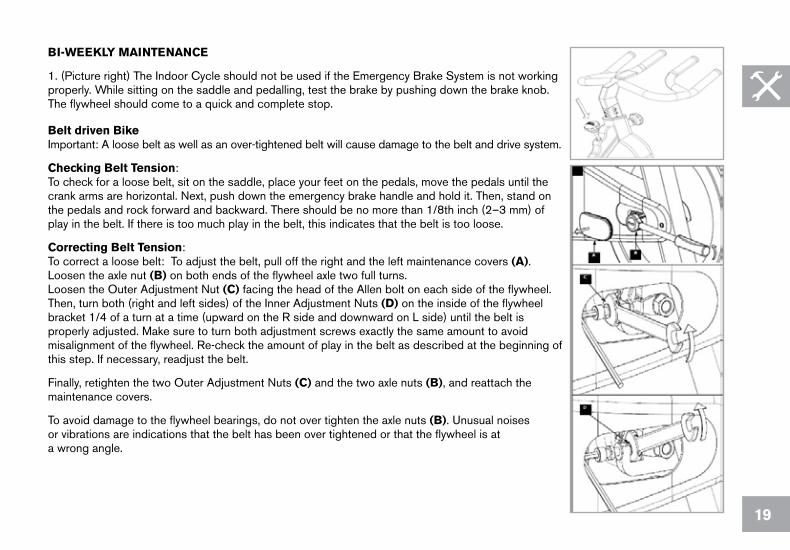
1. (Picture right) The Indoor Cycle should not be used if the Emergency Brake System is not working properly. While sitting on the saddle and pedalling, test the brake by pushing down the brake knob. The flywheel should come to a quick and complete stop. belt driven bike Important: A loose belt as well as an over-tightened belt will cause damage to the belt and drive system.
Checking belt Tension:To check for a loose belt, sit on the saddle, place your feet on the pedals, move the pedals until the crank arms are horizontal. Next, push down the emergency brake handle and hold it. Then, stand on the pedals and rock forward and backward. There should be no more than 1/8th inch (2–3 mm) of play in the belt. If there is too much play in the belt, this indicates that the belt is too loose.
Correcting belt Tension:To correct a loose belt: To adjust the belt, pull off the right and the left maintenance covers (A).Loosen the axle nut (b) on both ends of the flywheel axle two full turns.Loosen the Outer Adjustment Nut (C) facing the head of the Allen bolt on each side of the flywheel. Then, turn both (right and left sides) of the Inner Adjustment Nuts (D) on the inside of the flywheel bracket 1/4 of a turn at a time (upward on the R side and downward on L side) until the belt is properly adjusted. Make sure to turn both adjustment screws exactly the same amount to avoid misalignment of the flywheel. Re-check the amount of play in the belt as described at the beginning of this step. If necessary, readjust the belt.
Finally, retighten the two Outer Adjustment Nuts (C) and the two axle nuts (b), and reattach the maintenance covers.
To avoid damage to the flywheel bearings, do not over tighten the axle nuts (b). Unusual noises or vibrations are indications that the belt has been over tightened or that the flywheel is at a wrong angle.

20

21
LImITED HOmE USE wARRANTy wEIgHT CAPACITy = 290 lbs (131.5 kilograms).
5 yEAR wARRANTy: Frame construction, breakage, welding defects
2 yEAR wARRANTy: Handlebar and saddle assembly, brake system (excluding brake pad), lever handles and adjustment knobs, cranks, belt drive system, bottom bracket assembly, ball bearings, flywheel and hub assembly, powder coating, Plastic components such as chain guard and left side hub cover, sweat guard, Platform pedals (shoe cage system excluded), insert sleeves for handlebar and saddle post, leveling feet LAbOR • 1 yEARLivestrong Fitness shall cover the labor cost for the repair of the device for a period of 1 year from the date of the original purchase, so long as the device remains in the possession of the original owner.
6 mONTH wARRANTy Pedal straps, brake pads, pedal binding system, bottle holder, saddle
Product failures due to mechanical influence, negligent handling or improper use may void warranty pretension! frequent service and maintenance according to the procedures described in the owner’s manual are pre-requisite to uphold warranty.
EXCLUSIONS AND LImITATIONSwho IS covered:
• The original owner and is not transferable.
what IS covered:
Repair or replacement of a defective part and is the sole remedy of the warranty.
what IS NOT covered:
• Normal wear and tear, improper assembly or maintenance, or installation of parts or accessories not originally intended or compatible with the equipment as sold.
• Damage or failure due to accident, abuse, corrosion, discoloration of paint or plastic, neglect, theft, vandalism, fire, flood, wind, lightning, freezing, or other natural disasters of any kind, power reduction, fluctuation or failure from whatever cause, unusual atmospheric conditions, collision, introduction of foreign objects into the covered unit, or modifications that are unauthorized or not recommended by Livestrong Fitness.
• Incidental or consequential damages. Livestrong Fitness is not responsible or liable for indirect, special or consequential damages, economic loss, loss of property, or profits, loss of enjoyment or use, or other consequential damages of whatsoever nature in connection with the purchase, use, repair or maintenance of the equipment.
• Equipment used for commercial purposes or any use other than a single family or Household, unless endorsed by Livestrong Fitness for coverage.
• Equipment owned or operated outside the US and Canada. • Delivery, assembly, installation, setup for original or replacement units or labor or other
costs associated with removal or replacement of the covered unit.• Any attempt to repair this equipment creates a risk of injury. Livestrong Fitness is not
responsible or liable for any damage, loss or liability arising from any personal injury incurred during the course of, or as a result of any repair or attempted repair of your fitness equipment by other than an authorized service technician. All repairs attempted by you on your fitness equipment are undertaken AT YOUR OWN RISK and Livestrong Fitness shall have no liability for any injury to the person or property arising from such repairs.
SERVICE/RETURNS• In-home service is available within 150 miles of the nearest authorized repair center
(Mileage beyond 150 miles from an authorized service center is the responsibility of the consumer).
• All returns must be pre-authorized by Livestrong Fitness. • Livestrong Fitness’ obligation under this warranty is limited to replacing or repairing, at
Livestrong Fitness’ option, the same or comparable model at one of its authorized service centers.
• A Livestrong Fitness authorized service center must receive all equipment for which a warranty claim is made. This equipment must be received with all freight and other transportation charges prepaid, accompanied by sufficient proof of purchase.
• Replacement units, parts and electronic components reconditioned to As-new Condition by Livestrong Fitness or its vendors may sometimes be supplied as warranty replacement and constitute fulfillment of warranty terms.
• This warranty gives you specific legal rights, and your rights may vary from state to state.

LS9.9IC Rev. 1.0 | © 2009 Livestrong Fitness | Designed & Engineered in the U.S.A. | Made in China
Tel: 1-877-LIV-STNg (548-7864)Email: [email protected]
Livestrong fitness1600 Landmark Drive, Cottage grove wI, 53527
DO NOT RETURN TO THE RETAILER if you have any problems during assembly or if parts are missing.
For fast and friendly service, please contact one of our trained customer technicians via phone, email or our website.
CUSTOMER TECH SUPPORT
Every employee at Livestrong Fitness takes pride in providing you with a high quality product.
We want to know if you have a problem and we want to have an opportunity to correct it for you.
NOTE: Please read the Owner’s Manual fully before contacting Customer Tech Support. Additional product information is available on our website.
www.livestrongfitness.com