indirect fired gas heaters - · pdf filereceiving and warehousing labels attached to the...
TRANSCRIPT
Manual – INSTALLATION, OPERATION AND MAINTENANCE
Indirect Fired Gas HeatersPMI-IF
v000 – Issue Date: 04/09/15© 2015 Price Industries Limited. All rights reserved.

IndIrect FIred Gas HeatersTABLE OF CONTENTS
Installation Receiving and Warehousing ..........................................3General Handling Instructions ........................................3General Installation Notes ..............................................3Clearance to Combustibles ...........................................4Connecting the Flue for Outdoor Installation ..................5Air for Combustion ........................................................5Venting ..........................................................................5Connecting the Flue for Indoor Installation .....................7Air for Combustion ........................................................7Venting ..........................................................................8Vertically Vented Furnaces .............................................8Horizontally Vented Furnaces ......................................10Separated Combustion Systems .................................11Electrical Connections .................................................13Gas Piping ..................................................................14Gas Vent .....................................................................14Duct Furnaces .............................................................15Cooling .......................................................................15High Altitude................................................................15Indoor Units ................................................................15
General Operating InstructionsPier to Start-up............................................................16Start Up Procedures Precautions ................................16Gas Units ....................................................................16Start Up ......................................................................17Manifold Pressure Adjustment .....................................17Shut Down ..................................................................18Emergency Shut Down................................................18Service Shut Down ......................................................18
MaintenanceRecommended Quarterly Maintenance .......................19Recommended Yearly Maintenance ............................19
Standard Sequences & WiringStandard Utec Ignition Controller Sequence ................20Utec Troubleshooting Guide ........................................21PMI-IF Troubleshooting Guide .....................................22Standard 2 Stage Wiring .............................................23Standard 2 Stage Sequence of Operation ...................24Standard Modulating Wiring ........................................26Standard Modulating Sequence of Operation ..............28Markings (Labels) ........................................................30Warranty .....................................................................33
ATTENTION: Read this manual, heater submittal sheets and all labels attached to the heater carefully before attempting to install, operate or service these heaters! Check heater data plates for type of gas, model number and serial numbers. Retain this document for future reference.
WARNING Improper installation, adjustment, alteration, service or maintenance can cause property damage, severe personal injury or death. Please read this installation, operation and maintenance manual thoroughly before installing or servicing this equipment.
For your safety, if you smell gas, follow these instructions,
1. Open windows
2. Do not touch electrical switches
3. Extinguish any open flames
4. Call the gas supplier immediately
For your safety the use of gasoline or other flammable vapours and liquids in open containers in the vicinity of this heater is hazardous.
NOTE: Reference to Codes & Standards within this manual are correct as at the date this manual was prepared and may not be accurate at the time the heater(s) is/are installed.
Price Industries Limited 404 Egesz Street Winnipeg, MB R2R 1X5
ANSI Z83.8-2009 Commercial Industrial Gas Heating Equipment
CSA 2.6-2009 Industrial Package Gas Fired Package Furnaces
MANUFACTURED BY
1priceindustries.com | IndIrect FIred GAs HeAters - Manual
INDIRECT FIRED GAs HEATERsINSTALLATION
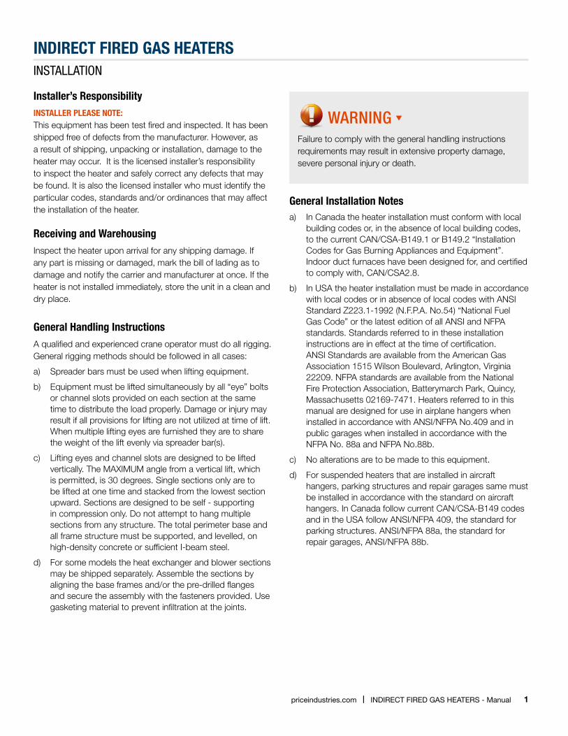
Installer’s ResponsibilityINsTAllER plEAsE NOTE:This equipment has been test fired and inspected. It has been shipped free of defects from the manufacturer. However, as a result of shipping, unpacking or installation, damage to the heater may occur. It is the licensed installer’s responsibility to inspect the heater and safely correct any defects that may be found. It is also the licensed installer who must identify the particular codes, standards and/or ordinances that may affect the installation of the heater.
Receiving and WarehousingInspect the heater upon arrival for any shipping damage. If any part is missing or damaged, mark the bill of lading as to damage and notify the carrier and manufacturer at once. If the heater is not installed immediately, store the unit in a clean and dry place.
General Handling InstructionsA qualified and experienced crane operator must do all rigging. General rigging methods should be followed in all cases:
a) Spreader bars must be used when lifting equipment.
b) Equipment must be lifted simultaneously by all “eye” bolts or channel slots provided on each section at the same time to distribute the load properly. Damage or injury may result if all provisions for lifting are not utilized at time of lift. When multiple lifting eyes are furnished they are to share the weight of the lift evenly via spreader bar(s).
c) Lifting eyes and channel slots are designed to be lifted vertically. The MAXIMUM angle from a vertical lift, which is permitted, is 30 degrees. Single sections only are to be lifted at one time and stacked from the lowest section upward. Sections are designed to be self - supporting in compression only. Do not attempt to hang multiple sections from any structure. The total perimeter base and all frame structure must be supported, and levelled, on high-density concrete or sufficient I-beam steel.
d) For some models the heat exchanger and blower sections may be shipped separately. Assemble the sections by aligning the base frames and/or the pre-drilled flanges and secure the assembly with the fasteners provided. Use gasketing material to prevent infiltration at the joints.
WARNING Failure to comply with the general handling instructions requirements may result in extensive property damage, severe personal injury or death.
General Installation Notesa) In Canada the heater installation must conform with local
building codes or, in the absence of local building codes, to the current CAN/CSA-B149.1 or B149.2 “Installation Codes for Gas Burning Appliances and Equipment”. Indoor duct furnaces have been designed for, and certified to comply with, CAN/CSA2.8.
b) In USA the heater installation must be made in accordance with local codes or in absence of local codes with ANSI Standard Z223.1-1992 (N.F.P.A. No.54) “National Fuel Gas Code” or the latest edition of all ANSI and NFPA standards. Standards referred to in these installation instructions are in effect at the time of certification. ANSI Standards are available from the American Gas Association 1515 Wilson Boulevard, Arlington, Virginia 22209. NFPA standards are available from the National Fire Protection Association, Batterymarch Park, Quincy, Massachusetts 02169-7471. Heaters referred to in this manual are designed for use in airplane hangers when installed in accordance with ANSI/NFPA No.409 and in public garages when installed in accordance with the NFPA No. 88a and NFPA No.88b.
c) No alterations are to be made to this equipment.
d) For suspended heaters that are installed in aircraft hangers, parking structures and repair garages same must be installed in accordance with the standard on aircraft hangers. In Canada follow current CAN/CSA-B149 codes and in the USA follow ANSI/NFPA 409, the standard for parking structures. ANSI/NFPA 88a, the standard for repair garages, ANSI/NFPA 88b.
2 IndIrect FIred GAs HeAters - Manual | priceindustries.com
INDIRECT FIRED GAs HEATERsINSTALLATION
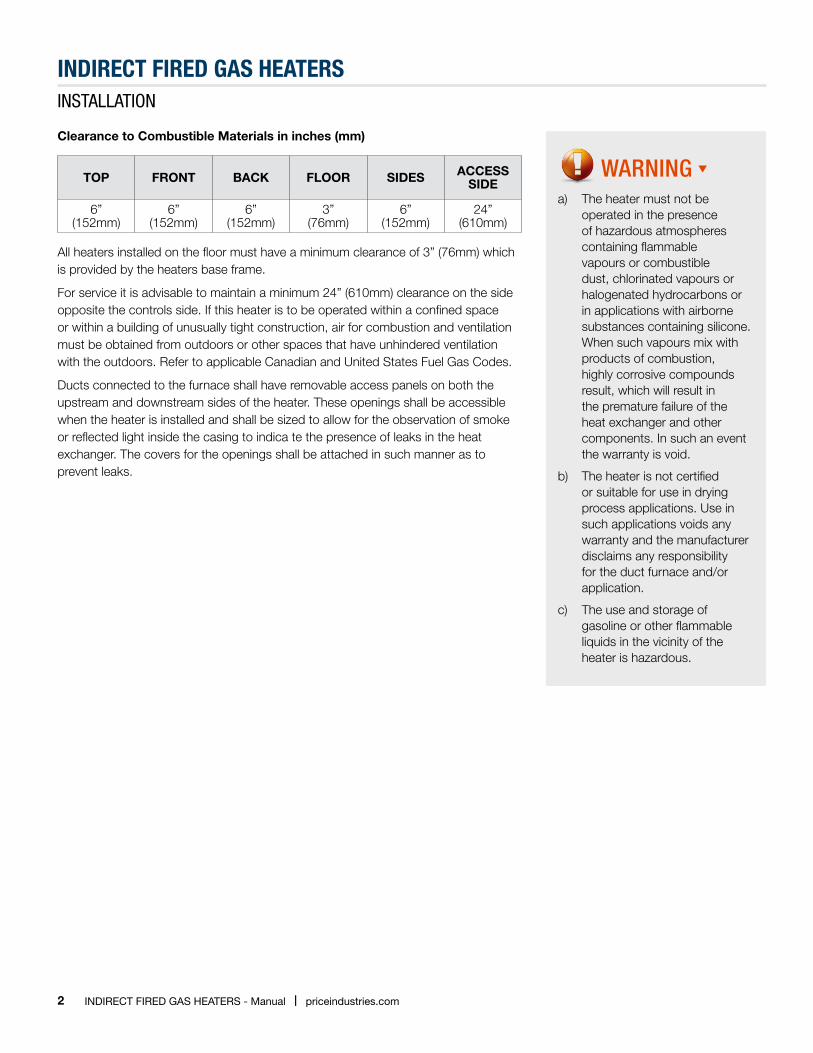
Clearance to Combustible Materials in inches (mm)
TOP FRONT BACK FLOOR SIDES ACCESS SIDE
6” (152mm)
6” (152mm)
6” (152mm)
3” (76mm)
6” (152mm)
24”(610mm)
All heaters installed on the floor must have a minimum clearance of 3” (76mm) which is provided by the heaters base frame.
For service it is advisable to maintain a minimum 24” (610mm) clearance on the side opposite the controls side. If this heater is to be operated within a confined space or within a building of unusually tight construction, air for combustion and ventilation must be obtained from outdoors or other spaces that have unhindered ventilation with the outdoors. Refer to applicable Canadian and United States Fuel Gas Codes.
Ducts connected to the furnace shall have removable access panels on both the upstream and downstream sides of the heater. These openings shall be accessible when the heater is installed and shall be sized to allow for the observation of smoke or reflected light inside the casing to indica te the presence of leaks in the heat exchanger. The covers for the openings shall be attached in such manner as to prevent leaks.
WARNING a) The heater must not be
operated in the presence of hazardous atmospheres containing flammable vapours or combustible dust, chlorinated vapours or halogenated hydrocarbons or in applications with airborne substances containing silicone. When such vapours mix with products of combustion, highly corrosive compounds result, which will result in the premature failure of the heat exchanger and other components. In such an event the warranty is void.
b) The heater is not certified or suitable for use in drying process applications. Use in such applications voids any warranty and the manufacturer disclaims any responsibility for the duct furnace and/or application.
c) The use and storage of gasoline or other flammable liquids in the vicinity of the heater is hazardous.
3priceindustries.com | IndIrect FIred GAs HeAters - Manual
INDIRECT FIRED GAs HEATERsINSTALLATION
Connecting the Flue (Venting) for Outdoor InstallationsAir for Combustion
The heat exchanger module must have an adequate supply of air for proper combustion of gas. Never locate the heater so that supply of air to the combustion air openings is obstructed. Combustion air inlet and flue gas outlet must be located in the same pressure zone. Refer to appropriate installation codes for required clearances to combustion air openings and flue gas outlets.
Venting
The vent termination must be located in accordance with the CAN/CSA-B149 Installation Code in Canada or the National Fuel Codes (ANSI Z223.1) in the US.
The venting system for outdoor units is a Category III, with vent products at positive pressure and up to 550°F (288°C). The cross-sectional area of the vent duct or pipe must be at least equal to the discharge area of the draft inducer.
The discharge opening must always be located in the same pressure zone as the combustion air inlet. Flue gases must be directed away from combustion air inlets to avoid recirculation into combustion air supply.
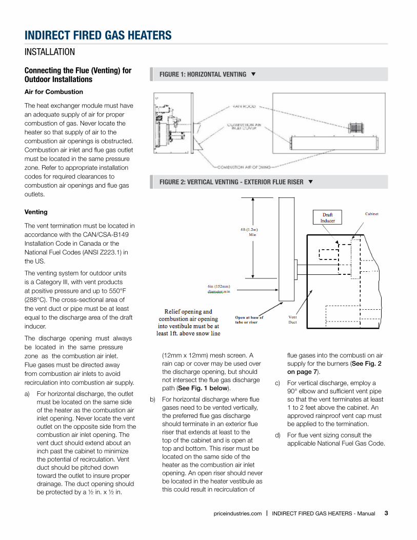
a) For horizontal discharge, the outlet must be located on the same side of the heater as the combustion air inlet opening. Never locate the vent outlet on the opposite side from the combustion air inlet opening. The vent duct should extend about an inch past the cabinet to minimize the potential of recirculation. Vent duct should be pitched down toward the outlet to insure proper drainage. The duct opening should be protected by a ½ in. x ½ in.
FIGURE 1: HORIzONTAl VENTING
FIGURE 2: VERTICAl VENTING - ExTERIOR FlUE RIsER
(12mm x 12mm) mesh screen. A rain cap or cover may be used over the discharge opening, but should not intersect the flue gas discharge path (See Fig. 1 below).
b) For horizontal discharge where flue gases need to be vented vertically, the preferred flue gas discharge should terminate in an exterior flue riser that extends at least to the top of the cabinet and is open at top and bottom. This riser must be located on the same side of the heater as the combustion air inlet opening. An open riser should never be located in the heater vestibule as this could result in recirculation of
flue gases into the combusti on air supply for the burners (See Fig. 2 on page 7).
c) For vertical discharge, employ a 90° elbow and sufficient vent pipe so that the vent terminates at least 1 to 2 feet above the cabinet. An approved rainproof vent cap must be applied to the termination.
d) For flue vent sizing consult the applicable National Fuel Gas Code.
4 IndIrect FIred GAs HeAters - Manual | priceindustries.com
INDIRECT FIRED GAs HEATERsINSTALLATION
Connecting the Flue (Venting) for Indoor InstallationsAir for Combustion
The heater must be installed in a location with adequate clearances for combustion air supply, service and inspection, and proper distances from combustible materials. The heater shall be located in such a manner that it does not interfere with the circulation of air in the heated space.
All fuel burning equipment must be supplied with air that enters into the combustion process and is then vented outdoors. Sufficient air must enter the heater location to replace the air exhausted through the vent system. Do not install heater in a confined space without providing wall openings to and from this space. If building construction is such that the normal infiltration does not provide sufficient air for combustion and venting, o utside air must be introduced in accordance with ANSI Z223.1, sections 1.3.4.2 and 1.3.4.3. Install air openings that provide a total free area in accordance with the following:
a) Air from inside the building – Opening of 1 sq. in. (645mm2) per 1,000 Btuh (293W) of input, but never less than 100 sq. in. (.06 m2)
b) Air from outside (ducted) – Opening of 1 sq. in. (645mm2) per 2,000 Btuh (586W)
Venting
All heaters must be vented outside of the heated space. In Canada all venting installations shall be in accordance with the latest editions CAN/CSA-B149 and in the USA all venting installations shall be in accordance with the latest editions of ANSI Z223.1, the National Fuel Gas Codes, Part 7 “Venting of Equipment”, or applicable provisions of local codes and ordinances.
The heater must be connected to a factory-built chimney or vent complying with the applicable code, standard or ordinance, or a masonry or concrete chimney lined with a material acceptable to the authority having jurisdiction.
The heater modules will be classified, and will be identified on the heater’s rating plate, in accordance with ANSI standards as follows:
Category I – Non-condensing appliance with negative vent pressure.
Category III – Non-condensing appliance with positive vent pressure.
5priceindustries.com | IndIrect FIred GAs HeAters - Manual
INDIRECT FIRED GAs HEATERsINSTALLATION
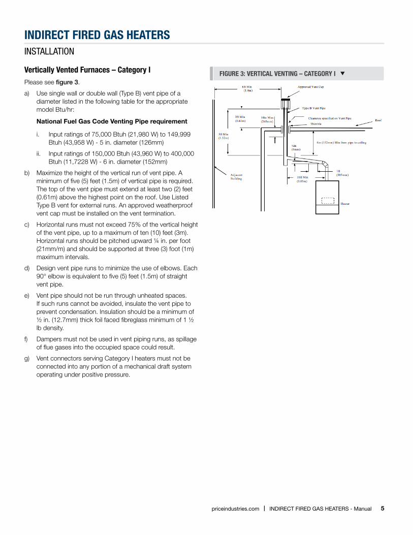
FIGURE 3: VERTICAl VENTING – CATEGORY I Vertically Vented Furnaces – Category I Please see figure 3.
a) Use single wall or double wall (Type B) vent pipe of a diameter listed in the following table for the appropriate model Btu/hr:
National Fuel Gas Code Venting Pipe requirement
i. Input ratings of 75,000 Btuh (21,980 W) to 149,999 Btuh (43,958 W) - 5 in. diameter (126mm)
ii. Input ratings of 150,000 Btuh (43,960 W) to 400,000 Btuh (11,7228 W) - 6 in. diameter (152mm)
b) Maximize the height of the vertical run of vent pipe. A minimum of five (5) feet (1.5m) of vertical pipe is required. The top of the vent pipe must extend at least two (2) feet (0.61m) above the highest point on the roof. Use Listed Type B vent for external runs. An approved weatherproof vent cap must be installed on the vent termination.
c) Horizontal runs must not exceed 75% of the vertical height of the vent pipe, up to a maximum of ten (10) feet (3m). Horizontal runs should be pitched upward ¼ in. per foot (21mm/m) and should be supported at three (3) foot (1m) maximum intervals.
d) Design vent pipe runs to minimize the use of elbows. Each 90° elbow is equivalent to five (5) feet (1.5m) of straight vent pipe.
e) Vent pipe should not be run through unheated spaces. If such runs cannot be avoided, insulate the vent pipe to prevent condensation. Insulation should be a minimum of ½ in. (12.7mm) thick foil faced fibreglass minimum of 1 ½ lb density.
f) Dampers must not be used in vent piping runs, as spillage of flue gases into the occupied space could result.
g) Vent connectors serving Category I heaters must not be connected into any portion of a mechanical draft system operating under positive pressure.
6 IndIrect FIred GAs HeAters - Manual | priceindustries.com
INDIRECT FIRED GAs HEATERsINSTALLATION
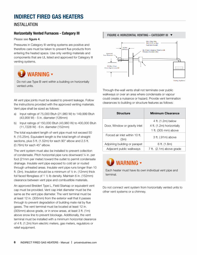
Horizontally Vented Furnaces - Category IIIPlease see figure 4.
Pressures in Category III venting systems are positive and therefore care must be taken to prevent flue products from entering the heated space. Use only venting materials and components that are UL listed and approved for Category III venting systems.
WARNING Do not use Type B vent within a building on horizontally vented units.
All vent pipe joints must be sealed to prevent leakage. Follow the instructions provided with the approved venting materials. Vent pipe shall be sized as follows:
a) Input ratings of 75,000 Btuh (21,980 W) to 149,999 Btuh (43,958 W) - 5 in. diameter (126mm)
b) Input ratings of 150,000 Btuh (43,960 W) to 400,000 Btuh (11,7228 W) - 6 in. diameter (152mm)
The total equivalent length of vent pipe must not exceed 50 ft. (15.25m). Equivalent length is the total length of straight sections, plus 5 ft. (1.52m) for each 90° elbow and 2.5 ft. (0.76m) for each 45° elbow.
The vent system must also be installed to prevent collection of condensate. Pitch horizontal pipe runs downward ¼ in. per foot (21mm per meter) toward the outlet to permit condensate drainage. Insulate vent pipe exposed to cold air or routed through unheated areas. Insulate vent pipe runs longer than 10 ft. (3m). Insulation should be a minimum of ½ in. (12mm) thick foil faced fibreglass of 1 ½ lb density. Maintain 6 in. (152mm) clearance between vent pipe and combustible materials.
An approved Breidert Type L, Field Starkap or equivalent vent cap must be provided. Vent cap inlet diameter must be the same as the vent pipe diameter. The vent terminal must be at least 12 in. (305mm) from the exterior wall that it passes through to prevent degradation of building mate rial by flue gases. The vent terminal must be located at least 12 in. (305mm) above grade, or in snow areas, at least 3 ft. (1m) above snow line to prevent blockage. Additionally, the vent terminal must be installed with a minimum horizontal clearance of 4 ft. (1.2m) from electric meters, gas meters, regulators or relief equipment.
FIGURE 4: HORIzONTAl VENTING – CATEGORY III
Through-the-wall vents shall not terminate over public walkways or over an area where condensate or vapour could create a nuisance or hazard. Provide vent termination clearances to building or structure features as follows:
Structure Minimum Clearance
Door, Window or gravity inlet
4 ft. (1.2m) below
4 ft. (1.2m) horizontally
1 ft. (305 mm) above
Forced air inlet within 10 ft. (3m)
3 ft. (.91m) above
Adjoining building or parapet 6 ft. (1.8m)
Adjacent public walkways 7 ft. (2.1m) above grade
WARNING Each heater must have its own individual vent pipe and terminal.
Do not connect vent system from horizontally vented units to other vent systems or a chimney.
7priceindustries.com | IndIrect FIred GAs HeAters - Manual
INDIRECT FIRED GAs HEATERsINSTALLATION
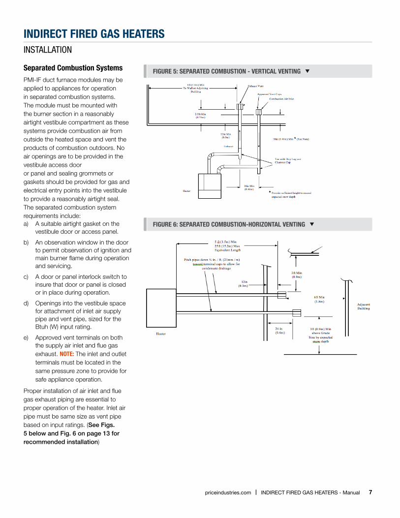
separated Combustion systemsPMI-IF duct furnace modules may be applied to appliances for operation in separated combustion systems. The module must be mounted with the burner section in a reasonably airtight vestibule compartment as these systems provide combustion air from outside the heated space and vent the products of combustion outdoors. No air openings are to be provided in the vestibule access dooror panel and sealing grommets or gaskets should be provided for gas and electrical entry points into the vestibule to provide a reasonably airtight seal. The separated combustion system requirements include:a) A suitable airtight gasket on the
vestibule door or access panel.
b) An observation window in the door to permit observation of ignition and main burner flame during operation and servicing.
c) A door or panel interlock switch to insure that door or panel is closed or in place during operation.
d) Openings into the vestibule space for attachment of inlet air supply pipe and vent pipe, sized for the Btuh (W) input rating.
e) Approved vent terminals on both the supply air inlet and flue gas exhaust. NOTE: The inlet and outlet terminals must be located in the same pressure zone to provide for safe appliance operation.
Proper installation of air inlet and flue gas exhaust piping are essential to proper operation of the heater. Inlet air pipe must be same size as vent pipe based on input ratings. (See Figs. 5 below and Fig. 6 on page 13 for recommended installation)
FIGURE 5: sEpARATED COMBUsTION - VERTICAl VENTING
FIGURE 6: sEpARATED COMBUsTION-HORIzONTAl VENTING
8 IndIrect FIred GAs HeAters - Manual | priceindustries.com
INDIRECT FIRED GAs HEATERsINSTALLATION
special ConsiderationsIn cases where malfunction of the heater may result in property damage or loss, a backup system or temperature sensitive alarm should be provided.
Electrical Connectionsa) This unit has been examined and tested for compliance
with Canadian Electrical Code CSA C22.2 no.0, CSA C22.2 no.3 and USA’s National Electrical Code.
b) All electrical work must conform to the requirements of CSA standard C22.1, Canadian Electric Code Part I, or the current NEC codes and/or local ordinances.
c) Control voltage is as indicted on the rating plate.
d) Follow the wiring diagram supplied with the heater.
e) If a space thermostat is used with the heater, locate the thermostat so the cold drafts and hot discharge air streams do not affect the performance of the thermostat. Do not mount the thermostat on the casing of the heater, as it will be affected by radiated and conducted heat. Refer to the instruction furnished with the thermostat for further details.
f) If any of the original wires as supplied with the heater must be replaced, they must be replaced with type TEW 105 degrees or its equivalent except where noted.
g) Temperature controllers, limit controllers, remote selector switches, door switches or any other auxiliary electrical items must be connected to the terminals provided as shown on the wiring diagram.
h) For heaters shipped in multiple sections, electrical connections between sections are to be made by the installer in the field.
i) Field wiring to be done by the installer is denoted by doted lines on the wiring diagram. Solid lines on the wiring diagram indicate factory wiring by the manufacturer.
j) The heater must be electrically grounded in accordance with local codes, or in the absence of local codes, with the CSA.C22.1 Canadian Electrical code and/or the National Electrical Code, ANSI/NFPA 70.
NOTE: Due to the nature of transport, check all bolts and fasteners for tightness.
Gas pipingk) All gas piping shall conform with local codes and
ordinances, or in the absences of local codes in Canada, installation must be in accordance with CAN/CSA- B149.1 for Natural Gas and B149.2 for Propane Gas and in the USA to the National Fuel Gas Code or ANSI Z223.1.
l) A manual gas shut-off valve must be installed immediately adjacent to the point where the gas supply enters the cabinet. The heater must be isolated from the gas supply system by closing its individual manual shut-off valve during any pressure testing of the gas supply piping system at test pressures equal to or less than ½ psi. Always use clean, scale -free pipe and malleable iron fittings, and remove all cutting and threading debris prior to connecting pipes. Firmly support the gas piping so that it cannot be dislodged from its installed position.
m) Gas piping must be sized for the total Btu input of the heater. Refer to the heater rating plate for total input.
n) Regulators used must be sized for the total Btu input of the heater.
o) For the unit to operate properly, the inlet gas pressure must be maintained at 5.0” W.C. for Natural Gas and 11.0” W.C. for Propane. Maximum inlet pressure must not exceed 13.0” W.C. to prevent damage to the gas valve.
p) A 1/8” NPT tap is provided on the inlet of the gas valve. A fitting suitable for connection to a pressure gauge capable of measuring gas pressure should be connected to each heater. Check pressures with all of the units operating at the same time.
q) A drip-leg shall be provided at any point in the gas line where condensate and sediment could collect.
Gas VentHigh gas pressure regulator (if required), low pressure regulator, pilot pressure regulator, gas pressure switch (if supplied), and normally open vent valve (if supplied) must be vented outside of building for an indoor heater (check with authorities having jurisdiction).
9priceindustries.com | IndIrect FIred GAs HeAters - Manual
INDIRECT FIRED GAs HEATERsINSTALLATION
Duct Furnacesa) A duct furnace shall be installed with an inlet duct, which
will provide air distribution equivalent to a straight run of duct having the same cross-section area as the inlet connection and not less than two equivalent diameters in length.
b) The ducts connected to the duct furnace must have removable access panels on both upstream and downstream sides of the duct. The opening must be accessible, and shall be of such size, that smoke or reflected light may be observed inside the casing to indicate the presence of leaks in the heating element. The cover for the opening shall be attached in such a manner as to prevent leaks.
c) The installation of the duct furnace must be adjusted to obtain an air throughout within the range specified on the appliance rating plate.
d) If a duct furnace is connected to a return air duct or any other inlet air restoration; the duct furnace shall be installed on the positive pressure side of the air-circulating blower.
CoolingWhen installed downstream from a refrigeration system, condensation will form and provisions shall be made to dispose of condensate.
High AltitudeInputs are derated 4% for each 1,000 ft (305m) elevation above 2,000 ft (610m).
Indoor UnitsInstall an indoor unit such that the gas ignition control system is not directly exposed to water spray, rain or dripping water.
10 IndIrect FIred GAs HeAters - Manual | priceindustries.com
INDIRECT FIRED GAs HEATERsGeneral OperatinG instructiOn
prior to start-Upa) Refer to the rating plate for fuel input and supply
pressures.
b) Do not attempt to start the burner if the heater is full of vapour gas, or if the combustion chamber is very hot.
c) Do not leave combustible material near the heater.
d) Shut off the manual fuel supply valve if the burner has been shut down for an extended period of time.
e) Ensure access doors are in place before starting the burner.
f) Do not start the burner unless the blower access doors are securely in place.
g) Refer to literature regarding controls, gas valves and other components.
start-Up procedure precautionsa) Ensure the main disconnect switch is in the “off” position.
b) Ensure the burner on-off switch is in the “off” position.
c) Check all electrical and gas connections and tighten if necessary.
d) Check main fans (by rotating fan shaft by hand), bearing setscrews, and pulley set screws. Ensure blowers are free to turn, vibration isolation shipping blocks are removed (if equipped), and shipped loose items (if supplied) are removed from inside blower sections.
e) Lubricate (if necessary) the burner and main fan motors. The specification on the motors for grease and oil shall be adhered to.
f) Check heater outlets for obstruction.
g) Check all fuse blocks to determine that all fusing is installed.
h) Set the operating controls (e.g. thermostat, remote panel switches) so as to allow proper operation of the heater.
i) Reset the motor starter by pushing the reset button, if so equipped. Ensure all blowers are rotating in the correct rotation.
j) Check building system gas supplies and be sure all lines are purged of air.
k) Check building system gas supply pressure
WARNING GAs UNITs
a) At maximum input the supply gas pressure must fall within the range specified on the heaters rating plate.
b) Check all piping for tightness and correct any signs of leaks.
start-Upa) Refer to start-up checklist and field report for correct
settings that are to be checked on the heater.
b) Check the supply fan motor thermal overload setting against the rating plate figure.
c) Ensure burner on-off switch is in the “off” position.
d) Verify that the heaters sequence of operation corresponds to sequence provided in the supplied “AS BUILT” literature.
e) Check supply fan motor amps against rating plate figure. If actual figure varies by +/- 20% from rating plate value, take corrective actions with respect to ductwork and accessories external to the heater or blower/motor drive adjustments making sure to follow manufactures rating for blower rotational speeds.
f) The thermal overloads must be set to appropriate motor performance after all adjustments have been made.
g) Follow sequence of operation supplied with the heater and perform necessary steps to initiate burner activation.
h) Once flame is detected the controller goes into “Power” and “Heat” mode.
i) Check heater performance as described on the factory test report, (include items such as stack temperature. CO-2 level, flame signals etc.) Readings obtained in the field should not deviate significantly from those obtained from the manufacturer.

11priceindustries.com | IndIrect FIred GAs HeAters - Manual
INDIRECT FIRED GAs HEATERsGeneral OperatinG instructiOn
FIGURE 7: HONEYWEll TWO sTAGE GAs VAlVE Manifold pressure Adjustmenta) The manifold pressure for high fire second stage should
be at 3.5” W.C., if it needs adjustment, adjust the HI Regulator on the two stage gas valve. (See Fig. 7 below).
b) The manifold pressure for Low Fire First Stage should be set at 1.2” W.C., if it needs adjustment, adjust the LO Regulator on the two stage gas valve. (See Fig. 7 below).
shut Down3. Emergency Shut Down
a) Set disconnect switch to “off” position.
b) Close the manual main fuel valve.
c) Set the burner on-off switch to “off” position.
2. Service Shut Down
a) Set the burner toggle switch to “off” position.
b) Close the manual main fuel valve.
c) Set the operating controls, (e.g. thermostat, remote panel switches), so as to prevent heating operation.
12 IndIrect FIred GAs HeAters - Manual | priceindustries.com
INDIRECT FIRED GAs HEATERsMaintenance
Regular maintenance is necessary to ensure the efficient operation and long life of this unit. This maintenance should be preformed by, or supervised by, qualified service personnel. A maintenance schedule should be prepared for the unit based on its application and location.
1. Recommended Quarterly Maintenance
a) Check for loose connections in the wiring.
b) Check the voltage at the heater while it is in operation.
c) Check motor amperage draws against rating plate values.
d) Inspect all contactors to ensure that they are clean and making good contact.
e) Check all fittings, valves and lines for leaks.
f) Check for proper combustion. Adjust if necessary.
g) Check the flame sensor signal (1.5-6.0mA), and clean if necessary.
h) Check the fuel supply pressure to the heater.
i) Check the heaters manifold pressure.
j) Clean or replace air filters if necessary. Replace filters only with type equivalent to those supplied with the heater by the manufacturer.
k) Check all dampers, linkages and damper actuators; adjust and tighten as required.
l) Check all belts. Adjust or replace as necessary.
m) Check all bearings and lubricate if necessary.
n) Check operation of all safety controls.
o) Oil burner fan.
p) Check all bearings to ensure tightness on shaft and lubricate if necessary.
q) Check ignition spark and adjust gap if necessary.
2. Recommended Yearly Maintenance
a) Perform the monthly quarterly maintenance recommended.
b) Inspect blower wheel and housing, clean if necessary.
c) Inspect all set screws on blower wheel and pulleys to ensure that they are secured to their respective shafts
d) Check flame supervisor controller.
e) Inspect all operating and safety controls. Clean and replace if necessary.
f) Inspect and clean the collection and disposal systems to ensure proper drainage.
NOTE: If ignition controller is replaced, ensure the control system is not exposed to water spray, rain or dripping water. Refer to individual manufacturer’s literature provided for maintenance requirements of optional equipment.
13priceindustries.com | IndIrect FIred GAs HeAters - Manual
INDIRECT FIRED GAs HEATERsStandard SequenceS & Wiring
Utec 1016-xxx Direct spark Ignition ControlSequence of Operation
a) Thermostat closes on call for heat providing 24 VAC to Ignition Control.
b) Draft Inducer is energized (@ line voltage).
c) Air Switch closes initiating 30-second pre-purge.
d) At end of pre-purge period, Spark and Gas Valve are energized for up to a 5-second ignition trial.
e) Burners ignite and carryover.
f) Flame is detected by flame sensor and control operates in steady state heating condition.
g) Heater continues in operation until the thermostat is satisfied.
h) Thermostat opens interrupting power to control and shutting unit off.
i) If ignition is not achieved within 5 seconds, the gas valve is shut off; the inducer continues to run for an inter-purge period. Additional ignition trials follow the specified sequence. If all trials (3) for ignition have occurred without proper ignition and flame detection, the control locks out.
j) Control may be brought out of lockout by cycling the thermostat or shutting off power for a minimum of 5 seconds.
k) If flame is lost once it has been established, the control will shut off the gas supply within 0.8 second and enter the inter-purge period. Control will initiate up to 3 additional trials per normal operation sequence. (To restart, refer to Item “j” above)
l) If flame sensor indicates presence of flame during purge period, when no flame should be present, the inducer will remain energized, but the gas valve will remain off until the cause of the “false flame” is removed.
m) If the air pressure switch is closed when the inducer is energized, or does not close after the inducer is energized, the control will wait 1 minute for the sir switch to open o r close, and then lock out. (To restart, refer to Item “j” above)
n) If the control detects power to the gas valve when it should be off, or not powered when it should be on, the control will go into lockout with all outputs off. (To restart, refer to item “j” above)
NOTE: Refer to control “Flash Code Key” if control is provided with LED indicator light.
LED Flash Code Key
On-Steady Control operation normal
1 Flash Open pressure switch, limit switch or flame rollout switch
2 Flashes Pressure switch stuck closed
3 Flashes Ignition / flame sense failure
4 Flashes Repeated flame losses
5 Flashes Internal control fault
14 IndIrect FIred GAs HeAters - Manual | priceindustries.com
INDIRECT FIRED GAs HEATERsStandard SequenceS & Wiring
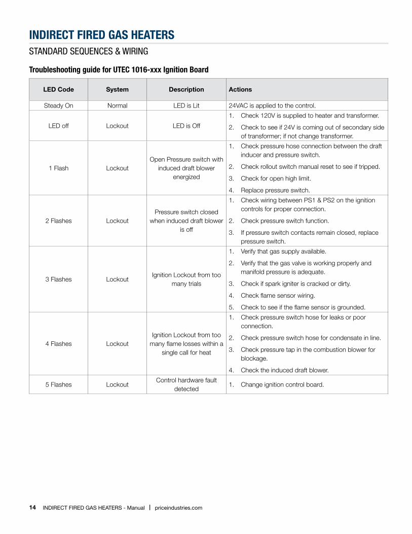
Troubleshooting guide for UTEC 1016-xxx Ignition Board
LED Code System Description Actions
Steady On Normal LED is Lit 24VAC is applied to the control.
LED off Lockout LED is Off
1. Check 120V is supplied to heater and transformer.
2. Check to see if 24V is coming out of secondary side of transformer; if not change transformer.
1 Flash LockoutOpen Pressure switch with
induced draft blower energized
1. Check pressure hose connection between the draft inducer and pressure switch.
2. Check rollout switch manual reset to see if tripped.
3. Check for open high limit.
4. Replace pressure switch.
2 Flashes LockoutPressure switch closed
when induced draft blower is off
1. Check wiring between PS1 & PS2 on the ignition controls for proper connection.
2. Check pressure switch function.
3. If pressure switch contacts remain closed, replace pressure switch.
3 Flashes LockoutIgnition Lockout from too
many trials
1. Verify that gas supply available.
2. Verify that the gas valve is working properly and manifold pressure is adequate.
3. Check if spark igniter is cracked or dirty.
4. Check flame sensor wiring.
5. Check to see if the flame sensor is grounded.
4 Flashes LockoutIgnition Lockout from too
many flame losses within a single call for heat
1. Check pressure switch hose for leaks or poor connection.
2. Check pressure switch hose for condensate in line.
3. Check pressure tap in the combustion blower for blockage.
4. Check the induced draft blower.
5 Flashes LockoutControl hardware fault
detected1. Change ignition control board.
15priceindustries.com | IndIrect FIred GAs HeAters - Manual
INDIRECT FIRED GAs HEATERsStandard SequenceS & Wiring
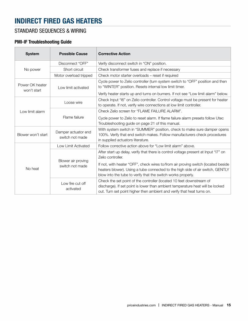
pMI-IF Troubleshooting Guide
System Possible Cause Corrective Action
No power
Disconnect “OFF” Verify disconnect switch in “ON” position.
Short circuit Check transformer fuses and replace if necessary
Motor overload tripped Check motor starter overloads – reset if required
Power OK heater won’t start
Low limit activated
Cycle power to Zelio controller (turn system switch to “OFF” position and then to “WINTER” position. Resets internal low limit timer.
Verify heater starts up and turns on burners. If not see “Low limit alarm” below.
Low limit alarm
Loose wireCheck Input “I6” on Zelio controller. Control voltage must be present for heater to operate. If not, verify wire connections at low limit controller.
Flame failure
Check Zelio screen for “FLAME FAILURE ALARM”.
Cycle power to Zelio to reset alarm. If flame failure alarm presets follow Utec Troubleshooting guide on page 21 of this manual.
Blower won’t startDamper actuator end
switch not made
With system switch in “SUMMER” position, check to make sure damper opens 100%. Verify that end switch makes. Follow manufacturers check procedures in supplied actuators literature.
No heat
Low Limit Activated Follow corrective action above for “Low limit alarm” above.
Blower air provingswitch not made
After start up delay, verify that there is control voltage present at Input “I7” on Zelio controller.
If not, with heater “OFF”, check wires to/from air proving switch (located beside heaters blower). Using a tube connected to the high side of air switch, GENTLY blow into the tube to verify that the switch works properly.
Low fire cut offactivated
Check the set point of the controller (located 10 feet downstream of discharge). If set point is lower than ambient temperature heat will be locked out. Turn set point higher then ambient and verify that heat turns on.
16 IndIrect FIred GAs HeAters - Manual | priceindustries.com
INDIRECT FIRED GAs HEATERsStandard SequenceS & Wiring
standard Wire Diagram & sequence- 2-stage, single furnace (subject to change without notice)
17priceindustries.com | IndIrect FIred GAs HeAters - Manual
INDIRECT FIRED GAs HEATERsStandard SequenceS & Wiring
pMI-IF Indirect Fired HeaterStandard 2 Stage Sequence Of Operation
A) System Switch “Winter”
1ST STAGE HEAT CALL
On activation of heater and after the 30 second purge time, the burner fires on low volume. The motorized fresh air damper opens fully. Once the damper motor end switch contact closes, the heater’s blower starts & runs continuously supplying 100% fresh air.
2ND STAGE HEAT CALL
The burner motor switches to high speed, after 5 seconds the burner goes to high volume.
B) System Switch “Summer”
Damper & blower operate as “A” above, burner is DE-ENERGIZED.
C) System Switch “Off”
Unit inoperative. Fresh air dampers closed.
NOTE: When the system switch is switched from winter to off, the burner motor will continue to run (high speed) for 5 seconds (to purge the heat exchanger), the supply fan will continue to run, the dampers will remain ENERGIZED for 30 seconds (to cool down the heat exchanger).
When the system switch is switched from winter to summer, the burner fan will continue to run
(to purge the heat exchanger) for 5 seconds.
The first time heating mode is “ENERGIZED” the supply fan will stop & restart, after burner fires & dampers open.
Additional Controls:
• The burner will try for ignition up to 3 times on initial start-up.
– If main flame is not proven there is a 30 second purge cycle before the next 15-second trial for re-ignition
– After the 3rd attempt, if the flame is not proven, the burner will shut down
– The system switch must then be cycled before the heater will start again
– If main flame is lost during operation the burner will try for ignition up to 3 times
• low limit set at 40°F to shut down the heater (after a 5 minute (adjustable) time delay on start-up) if the supply air temperature below its set point is sensed
Zelio Inputs & Outputs
• I1 – damper/blower on
• I2 – heat mode
• I3 – blower ok
• I5 – burner on
• I6 – low limit
• Q1 – power damper
• Q2 – power stage 2 heat
• Q3 – power high volume (main gas valve)
• Q4 – power 2 stage furnace control module
18 IndIrect FIred GAs HeAters - Manual | priceindustries.com
INDIRECT FIRED GAs HEATERsStandard SequenceS & Wiring
standard Wire Diagram & sequence-24 volt, 1stage modulating, 1stage on-off, drawing1of 2 (subject to change without notice)
19priceindustries.com | IndIrect FIred GAs HeAters - Manual
INDIRECT FIRED GAs HEATERsStandard SequenceS & Wiring
standard Wire Diagram & sequence-120 volt, 1stage modulating, 1stage on-off, drawing 2 of 2 (subject to change without notice)
20 IndIrect FIred GAs HeAters - Manual | priceindustries.com
INDIRECT FIRED GAs HEATERsStandard SequenceS & Wiring
pMI-IF Indirect Fired HeaterStandard Modulating Sequence of Operation
A) System Switch “Winter”
On activation of heater, after the 30 second purge time, the burner fires & modulates to maintain discharge temperature as set at the remote temperature selector on the remote panel.
The motorized fresh air damper opens fully. Once the damper motor end switch contact closes, the unit blower starts & runs continuously supplying 100% fresh air.
B) System Switch “Summer”
Damper & blower operate as “A” above, burner is DE-ENERGIZED.
C) System Switch “Off”
Unit inoperative. Fresh air dampers closed.
NOTE: When the system switch is switched from winter to off, the burner motor will continue to run for 5 seconds (to purge the heat exchanger), the supply fan will continue to run, the dampers will remain ENERGIZED for 30 seconds (to cool down the heat exchanger).
When the system switch is switched from winter to summer, the burner fan will continue to run (to purge the heat exchanger) for 5 seconds.
The first time heating mode is “ENERGIZED” the supply fan will stop & restart, after burner fires & dampers open.
Additional Controls:
• The burner will try for ignition up to 3 times on initial start-up.
– If main flame is not proven there is a 30 second purge cycle before the next 15-second trial for re-ignition
– After the 3rd attempt, if the flame is not proven, the burner will shut down
– The system switch must then be cycled before the heater will start again
– If main flame is lost during operation the burner will try for ignition up to 3 times
• Auto low limit set at 40°F to shut down the heater (after a 5 minute (adjustable) time delay on start-up) if the supply air temperature below its set point is sensed
• Inlet air controller (on/off furnace) (set by others) brings on the on/off furnace if the inlet air temperature drops below its set point
Zelio Inputs & Outputs
• I1 – damper/blower on
• I2 – heat mode
• I3 – low fire cut out
• I4 – high speed burner fan (modulating furnace)
• I5 – burner on (modulating furnace)
• I6 – low limit
• I7 – airflow OK
• I8 – inlet air controller (on/off furnace)
• I9 – burner on (on/off furnace)
• Q1 – power damper
• Q2 – power amplifier
• Q3 – power ignition controller (modulating furnace)
• Q4 – high volume (modulating furnace)
• Q5 – power ignition controller (on/off furnace)
• Q8 – low speed burner motor (modulating furnace)
• Q9 – high speed burner motor (modulating furnace)
• QA – high speed burner motor (on/off furnace)
21priceindustries.com | IndIrect FIred GAs HeAters - Manual
INDIRECT FIRED GAs HEATERsNOTES

This document contains the most current product information as of this printing. For the most up-to-date product information, please go to priceindustries.com
© 2015 Price Industries Limited. All rights reserved.