indiana department of transportation - in.gov · pdf filewelding ... (quality control...
TRANSCRIPT
INDIANA DEPARTMENT OF TRANSPORTATION
DIVISION OF CONSTRUCTION MANAGEMENT
MANUAL OF INSTRUCTIONS FOR
STRUCTURAL STEEL SHOP INSPECTION
July 2007

(This page Intentionally Blank)
FOREWORD This manual is intended to be a guide and reference tool for steel shop inspectors. This guide is intended to be a “living” document. As such, suggestions and comments are always welcome from the users of this manual. This manual in no way, shape, or form is intended to replace the Standard Specifications and is not a part of the Standard Specifications. Thus the Fabricator is not bound by any of the requirements or directions contained herein. Special thanks to the following (in alphabetical order) for their assistance with the preparation and revising of this manual: Gary Chestnut Don Leonard Kevin Day Courtney Mack Kim Eaton Jim Reilman Mark Fligor Bob Wild It is our intention that this manual be reviewed and updated on a 5 year cycle. Interim revisions may be issued at any time.

(This page Intentionally Blank)
i
TABLE OF CONTENTS 1. Definitions & Terms .......................................................................................................................... 1 2. Introduction........................................................................................................................................ 5 3. Notification & Prefabrication ............................................................................................................ 9 4. Procurement & Initial Review ........................................................................................................... 11 5. Material Preparation .......................................................................................................................... 15 6. Fit-Up................................................................................................................................................. 19 7. Welding.............................................................................................................................................. 21 8. Non-destructive Weld Testing........................................................................................................... 27 9. Assemble & Ream ............................................................................................................................. 31 10. Cleaning & Painting .......................................................................................................................... 33 11. Final Acceptance & Shipping............................................................................................................ 35 Appendix Prefabrication Meeting Agenda......................................................................................................... A-1 Summary of Mill Test Reports .......................................................................................................... A-2 Weekly Progress Reports................................................................................................................... A-3 List of Approved Welders, Welding Operators, & Tackers ..............................................................A-4 Completed Materials Report.............................................................................................................. A-5

ii
(This page Intentionally Blank)
1
1. DEFINITIONS AND TERMS Wherever in this manual the following abbreviations are used, they are to be construed the same as the respective expressions represented. AASHTO – American Association of State Highway and Transportation Officials ASTM – American Society for Testing and Materials AWS – American Welding Society BWC – Bridge Welding Code, current edition (abbreviation for the AASHTO/AWS D1.5 Bridge Welding Code) Camber – a slight convexity, arching, or curvature of a beam or girder for the purpose of offsetting the deflection when loads are applied. Central Office – INDOT Office located at 100 N Senate Ave in the Indiana Government Center North Building. Contractor – The individual, partnership, firm, corporation, or combination of same contracting with or desiring to contract with the Department for performance of prescribed work. CVN – Charpy V-Notch. A dynamic test which measures the energy absorbed by the material prior to breaking. See ASTM A673 and A370 and Standard Specifications 910 for additional information. DTE – District Testing Engineer District Office – INDOT Office located within one of the six Districts DFT – Dry Film Thickness. A measure of the thickness of a coating when dry; expressed in mils. (A mil is equal to 0.001 inch) ESW – Electroslag Welding. A welding process that produces coalescence of metals with molten slag that melts the filler metal and the surfaces of the workpieces. The weld pool is shielded by this slag which moves along the full cross section of the joint as welding progresses. The process is initiated by an arc that heats the slag. The arc is then extinguished by the conductive slag, which is kept molten by its resistance to electric current passing between the electrode and the workpieces. Fabricator – Individual or firm who has subcontracted with the prime contractor to produce the steel necessary for the contract. Fabrication Shop – Place where the individual or firm performs the cutting, bending, drilling, lay down, and shop assembly of the steel required for the contract. Faying surface – the mating surface of a member that is in contact with or in close proximity to another member to which it is to be joined.
2
FCAW – Flux Cored Arc Welding. An arc welding process that uses an arc between a continuous filler metal electrode and the weld pool. The process is used with shielding gas from a flux contained within the tubular electrode with or without additional shielding from an externally supplied gas, and without the application of pressure. FCM – Fracture Critical Member. Fracture critical members or member components are tension members or tension components of members whose failure would be expected to result in collapse of a bridge. Tension components of a bridge member consist of components of tension members and those portions of a flexural member that are subject to tension stress. Any attachment having a length in the direction of the tension stress greater than 100 mm (4 inches) that is welded to the tension area of a component of a “fracture critical” member should be considered part of the tension component and, therefore, should be considered “fracture critical.” Frequency Manual – Frequency of Sampling and Testing Manual. The manual that outlines the sampling and testing requirements of materials for acceptance purposes on INDOT contracts. INDOT – Indiana Department of Transportation. The agency as constituted under the laws of Indiana for the administration of highway work. Inspector – The individual charged with ensuring that quality assurance goes into each contract. This person is responsible for observing and documenting the operations of the fabricator at the fabrication shop. Lamination – a flaw caused by imperfections in the steel, whereby a thin strip of metal separates or debonds from the steel beam or plate. Mill to bear – a bearing condition sometimes specified on the plans or shop drawings, typically where a bearing stiffener is to be installed. AWS 3.5.1.9 indicates “…all steel components shall fit within 1/32 inch for 75% of the projected area of the web and stiffeners.” MT – Magnetic Particle Testing. A non-destructive testing method that enhances the visual inspection of weld and base metal surfaces. It may also reveal near-surface discontinuities. MTR – Mill Test Report. A certified report that accompanies each shipment of steel. The mill test report certifies that the steel conforms to the project specifications and reveals the chemical composition of the steel. NDT – Nondestructive Testing. A quality conformance test that does not eliminate the future usage of the product being tested. PQR – Procedure Qualification Record. A document providing the actual welding variables used to produce an acceptable test weld and the results of tests conducted on the weld to qualify a WPS. PT – Penetrant Test or Liquid Penetrant Test or Dye Penetrant Test. A non-destructive testing method that enhances the visual inspection of weld and base metal surfaces. QA – Quality Assurance. A planned system of review and inspection procedures conducted by personnel not directly involved in the fabrication process. Reviews verify that quality objectives
3
were met, ensure that the fabrication represents the best possible efforts of those directly involved in the fabrication, and are a verification that the resulting steel members concur with the design drawings. QC – Quality Control. The self-policing of a fabricator to ensure that the product meets the design drawings and specifications. It provides routine and consistent checks to ensure correctness and completeness. QCP – Quality Control Plan. A written plan detailing how a fabricator is going to control the quality of the steel member as it is being fabricated in order to produce steel in accordance with the specifications and design drawings. RT – Radiographic Test. A non-destructive testing method where x-rays or gamma rays are used. This method is suitable for testing welded joints that can be accessed from both sides. Although this is a slow and expensive NDT method, it is a dependable way to detect porosity, inclusions, cracks, and voids in weld interiors. RT makes use of X-rays or gamma rays. The basic principle of radiographic weld inspection is the same as that of medical radiography. Penetrating radiation is passed through a solid object (in this case, a weld rather than part of the human body) onto photographic film, creating an image of the object’s internal structure on the film. SAW – Submerged Arc Welding. An arc welding process that uses an arc or arcs between a bare metal electrode or electrodes and the weld pool. The arc and molten metal are shielded by a blanket of granular flux on the workpieces. The process is used without pressure and with filler metal from the electrode and sometimes from a supplemental source (welding rod, flux, or metal granules). SMAW – Shielded Metal Arc Welding. An arc welding process with an arc between a covered metal electrode and the weld pool. The process is used with shielding from the decomposition of the electrode covering, without the application of pressure, and with filler metal from the electrode. SSPC – formerly Steel Structures Painting Council, now the Society for Protective Coatings. A non-profit association that is focused on the protection and preservation of concrete, steel, and other industrial and marine structures and surfaces through the use of high performance industrial coatings. SSPC is a leading source of information on surface preparation, coating selection, coating application, environmental regulations, and health and safety issues that affect the protective coatings industry. Tight fit – a bearing condition sometimes specified on the plans or shop drawings, typically where an intermediate stiffener is to be installed. AWS 3.5.1.10 indicates “Where tight fit of intermediate stiffeners is specified, it shall be defined as allowing a gap of up to 1/16 inch between stiffener and flange.” UT – Ultrasonic Test. Ultrasonic testing can be used on ferrous and nonferrous materials and often is suited for testing thicker sections accessible from one side only. In general, it can detect finer linear or planar defects than can RT. UT makes use of mechanical vibrations similar to sound waves but of higher frequency. A beam of ultrasonic energy is directed into the object to be tested. This beam travels through the object with insignificant energy loss, except when it is intercepted and reflected by a discontinuity.
4
WPS – Welding Procedure Specification. A document providing the required variables for a specific application to assure repeatability by properly trained welders and welding operators.
5
2. INTRODUCTION Structural Steel Inspectors are INDOT personnel and consultants that are assigned to Structural Steel Fabrication Shops for the purpose of inspection, and are the contacts between INDOT and the steel fabricator. Steel fabrication involves principles, skills, and knowledge not associated with other types of field construction inspection. Steel fabrication inspection requires constant and close attention to details and procedures required by both INDOT and the AASHTO/AWS D1.5 Bridge Welding Code to ensure that the work performed by the fabricator is of the quality required by the contract when the Completed Materials Certification (IC-708) is signed by the Inspector. Therefore it is necessary that each Inspector perform these assignments using skills and knowledge to achieve the ultimate performance of the design. The actual erection and construction of a structure begins when the final approved drawings reach the shop fabrication floor and continues through field erection until the structure is put to use. The shop fabrication inspector (Quality Control Inspector, or QC) is responsible for the ultimate completion of a structure in accordance with the design. (The INDOT Inspector is responsible for the Quality Assurance or QA portion of the work.) Shop practices and procedures differ with each fabricator and with each crew of men within each plant. It is not our intent to specify each shop procedures of how each fabricator is to proceed, except to specify that all procedures and workmanship are to be in accordance with the specifications and details on the plans. Two most frequently used specifications and codes used for INDOT’s purposes are the Indiana Department of Transportation Standard Specifications, which are referred to as the “Standard Specifications”, and the AASHTO/AWS D1.5 Bridge Welding Code, which is referred to as the “BWC”. These along with other codes, specifications and terms are defined in the front of this manual. Purpose The primary purpose of this manual is to establish a more uniform policy of inspection procedure and standards throughout the State for inspection of steel fabrication. Also included is documenting the activities involved in shop inspection and providing a record of the conditions and situations at the time of fabrication. Our objective is to assure INDOT that the fabricated structure has been achieved in accordance with plans and specifications. Lines of Authority & Communication The Inspector has the authority, using plans, the BWC, Standard Specifications and contract special provisions to make decisions on acceptance or rejection of materials. Solutions to any discrepancies or disagreements with the fabricator, which the Inspector feels is beyond his authority to make, should immediately be referred to the District Testing Engineer (DTE). When necessary, the Central Office, Division of Construction Management is available to review and discuss situations that cannot be resolved between the Fabricator, the Inspector, and the DTE. These situations should only be reported to Central Office through the DTE.
6
Safety Safety is of utmost importance to the Inspector when working in the fabrication facility. At no time should the Inspector be put in a potentially dangerous location or position in the fabrication facility while performing the inspection duties. The fabricator must make all materials available to the Inspector such that it can safely be inspected. The Inspector must follow all safety rules and regulations of the fabricating facility including wearing all required personal protective equipment (PPE). INDOT will supply the Inspector with the necessary PPE. Equipment INDOT will supply the Inspector with all the necessary inspection equipment to perform the duties. Where possible, the Inspector should not use the fabricator’s equipment to perform the inspections. In the case of any discrepancies with the fabricator of readings or interpretations of test results using the Inspector’s equipment, the Inspector will make available to the fabricator the equipment calibration records. Also, the Inspector will ask the fabricator to see the record of calibration for the fabricator’s equipment. The inspector will keep the inspection equipment in calibration at all times. Most calibrations are done on a semi-annual or annual basis and will be done either at the District Testing lab or sent out for calibration. Equipment which the Inspector does not use every day is kept at the District Testing office and will be available to the Inspector. Plans & Specifications A thorough knowledge of the plans and specifications is essential before the Inspector begins work on each contract. The Inspector should be given a stamped “Approved” set of shop drawings from the DTE along with any special provisions for the contract. These drawings are stamped approved by Central Office Division of Structural Engineering or their designated representative. Use of any drawings other than those approved by Central Office Division of Structural Engineering or their designated representative are at the fabricator’s risk. A transmittal letter should accompany the shop drawings listing each approved drawing and any revisions. Along with the shop drawing the Inspector should receive a stamped approved set of the fabricators welding procedures. The Inspector should also receive from the District Office a set of design drawings for the contract. The Inspector is encouraged to review the design drawings with the shop drawings for any discrepancies. If the Inspector does find any discrepancies between the design drawings and the fabricators shop drawings the discrepancies should immediately report these to the DTE. The design drawings, contract information books, and approved shop drawings are available electronically from the Internet site and the Department’s Y: drive respectively.
7
Inspector Requirements The Inspector must have a thorough knowledge of the following in order to perform the duties: INDOT Standard Specifications and Contract Special Provisions AASHTO/ANSI/AWS D1.5 Bridge Welding Code INDOT Frequency Manual SSPC Specifications Shop Drawings INDOT Design Drawings ASTM A6 The Inspector is required to read and interpret the following: Mill Test Reports (MTR) Weld Procedure Specifications (WPS) Welder Qualification Records Weld Procedure Qualification Records (PQR) Magnetic Particle Test Reports (MT) Penetrant Test Reports (PT) Radiographic Test Reports (RT) Ultrasonic Test Reports (UT) Sections of the Manual The following sections of this manual have been put together in order of the sequence in which most contracts flow through the fabricators facility. Fabricators do not always follow this sequence and the Inspector should not expect the fabricator to do so. Notification & Prefabrication Procurement & Initial Review Material Preparation Fit-up Welding Non-destructive Weld Testing Assemble & Ream Cleaning & Painting Final Acceptance & Shipping

8
(This page Intentionally Blank)
9
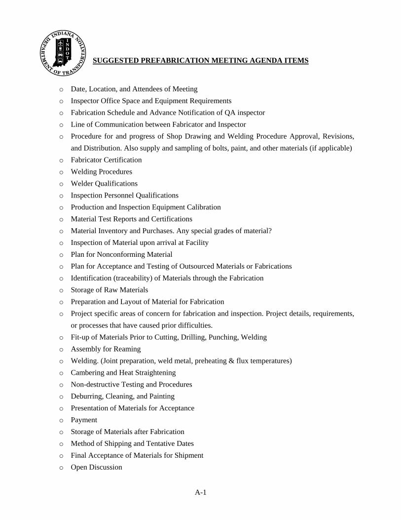
3. NOTIFICATION & PREFABRICATION The contractor should give the DTE a written notice ten days in advance of the date on which the fabrication is intended to start. This notice should state the name and location of the fabricator for the contract. A copy of this notice should be given to the Inspector immediately so that the Inspector may contact the fabricator and request to have a prefabrication meeting. This meeting should be held on or before the start up date of fabrication. The time and location of the meeting should be mutually agreed upon by the fabricator and the Inspector. Normally this meeting is held at the fabricators plant. If the fabricator requests this meeting to be held at another location other than the fabrication plant then the Inspector must agree on the meeting location. It is highly recommended that this meeting take place at the fabrication plant. The Inspector should create the agenda for the meeting using the “Prefabrication Meeting” form contained in the Appendix of this manual. This form is designed to address what is expected of the fabricator and to establish lines of communication between the fabricator and the Inspector. By addressing these items ahead of the fabrication process the Inspector and fabricator will have guide to follow and should be able to avoid disagreements as to what is expected and how any discrepancies should be handled. The Inspector will notify the DTE of the time and place of the meeting, and the DTE should attend if available. After the Inspector has created an agenda (or an outline) for the prefabrication meeting, the Inspector should review the agenda with the DTE. The Inspector and DTE should then make any changes to the agenda. Next, the Inspector is to give a copy of the agenda to the fabricator prior to the prefabrication meeting. The Inspector should obtain from the DTE a stamped approved set of the fabricators shop drawings prior to the meeting. The Inspector should not obtain these drawings from the fabricator. Along with the drawings should be the special provisions for the contract. It is also recommended that the Inspector receive a set of the design drawings for the contract. This should allow the fabricator time to prepare responses and paperwork for the agenda and hopefully expedite the meeting. By doing this ahead of time, long draw out prefabrication meetings can be avoided. At the prefabrication meeting the Inspector should take notes on the spaces provided on the meeting form. A copy of these notes should be made available to all parties in attendance. Personnel in attendance at these meetings should be the Inspector, the DTE, the design engineer, the fabricator quality control manager, the fabricator engineering manager, the fabricator shop superintendent and welding foreman. On occasions the general contractor will have a representative sit in the meeting. Either before or after the prefabrication meeting the Inspector should tour the fabrication facility with a representative of the fabricator. The Inspector will also review the office facilities provided by the fabricator before the meeting to see that all Standard Specification requirements are met. This is done prior to the meeting so that any issues with the facilities provided to the Inspector can be brought up at the meeting and resolved.

10
(This page Intentionally Blank)
11
4. PROCUREMENT & INITIAL REVIEW Steel Identification On the initial visit to the shop the Inspector should request the mill test reports for the material on hand. According to 711, the mill test reports may be provided prior to or concurrent with fabrication. Letters of certification that these reports are on file in the fabricator’s office are not acceptable. The Inspector should not allow material to be fabricated on prior to receiving mill test reports from the fabricator. The Inspector should review these mill test reports in conjunction with the shop drawings and plans. Then the “Summary of Mill Test Reports” form contained in the Appendix of this manual should be filled in. The mill test report is a certification of the qualities existing in a given shipment of steel and does not necessarily certify that these qualities are within the limits of the ASTM A709 specification for the particular grade of steel specified. The Fabricator should review all mill test reports for conformity to the ASTM A709 requirements for the grade of steel furnished. Mill test reports should be furnished for all steel in accordance with the Standard Specifications 711. Heat numbers listed on the test report must correspond with the heat numbers stamped, stenciled or tagged on the material. The amount of material listed on the reports must be sufficient to cover the quantity called for on the plans. The Inspector should check the chemical analysis and mechanical test results listed on the mill test reports. These results must conform to the ASTM A709 specification of the material called for on the plans. If there is any doubt as to the grade of steel, the steel should not be accepted for use on the contract. All material used on INDOT contracts must meet the “Buy American” requirements of the Standard Specifications and any contract special provisions. All steel is required to be marked in accordance with the requirements of ASTM A6 prior to delivery to the fabricator’s shop or other point of use. Identification by Fabricator The fabricator should identify material by marking with paint, crayon, steel die stamping, tags, or other means. The fabricator’s identification mark system should be established and on record for the information of the inspector prior to the start of fabrication. The fabricator should put the contract number on the material. The contract number and piece marks are found on the fabricators shop drawings and bill of materials. A copy of the fabricators bill of material should be made available to the Inspector. This document is a record of the raw material used on the contract and shows the breakdown of pieces cut from each piece of raw material. Heat numbers along with size and piece marks are shown on the bill of materials. This is a good document for the Inspector to use in tracking material used on the contract. The fabricator should identify a completed piece for the structure with a shipping mark. These shipping marks are normally shown in capital letters with numbers. A shipping piece may be one individual piece of steel and other times it can be made up of several pieces of steel that have been bolted or welded and bolted together. Individual pieces of steel making up a shipping piece are usually given piece marks and these may be in lower case letters with numbers.
12
The fabricators piece mark, which should be shown on his shop drawings, does not have to be permanently marked on the shipping piece. Many fabricators use crayons or soap stones to put the piece marks on the individual pieces. Once these pieces are fit to the member the piece marks may not be legible. Pieces used for main members that require Charpy V-Notch (CVN) testing should have their heat numbers permanently stenciled on them using “low stress” stencils in locations designated in the Standard Specifications 711. These are usually the main load carrying members such as WF beams and their splice plates. Also webs and flanges of plate girders, along with their splice plates, require this. Some beam and girder stiffener plates also require the heat numbers be stamped depending upon locations and design requirements. All pieces requiring CVN testing should be shown on the fabricator’s approved shop drawings and also on the bill of material. It is very important that only material with CVN requirements be used in these locations. The Inspector must never let any material requiring CVN testing go through the fabrication stages without proper documentation and marking. Some materials require blasting prior to fabrication and their identity can be lost during the blasting operation. The fabricator should either stencil, attach metal tag or some other means of identification to these pieces prior to the blasting operation to retain their identity. The inspector should ask the fabricator ahead of fabrication what the method of identification will be. If the identity of the material is lost during blasting the Inspector should not accept the material for use on the contract. Material Inspection All steel should be inspected in the receiving yard of the fabricator as it is delivered from the supplier. The fabricator should inspect the material as it is being unloaded from the carrier so that nonconforming material can be immediately returned if necessary. The fabricator should notify the Inspector of any material being received so that the Inspector may be present. If this is not possible, another good opportunity to inspect material is during the thermal cutting process when heat numbers are recorded as larger plates are cut into their components. A proper inspection at this stage can prevent later rejection of material found defective. Defects in materials should be noted, marked and repaired at this time if possible. The Inspector must be notified of any repairs to be made at this time and only repairs allowed per the BWC and ASTM A6 may be made. Some materials such as Fracture Critical Material (FCM) do not allow for mill repairs. The fabricator should check this material closely as it is being unloaded for any mill repairs. The Inspector should also pay particular attention to FCM material examining it prior to use for mill repairs. Any mill or fabricator repairs made to FCM material require documentation and approval by INDOT. See Section 12 of the BWC for FCM requirements. Some defects not determined with this yard examination will be discovered during fabrication. Acceptance of the material at this stage does not prevent later rejection if the material is found to be of a lower grade or defects are discovered during fabrication. In making a decision on the acceptance or rejection of materials, the first consideration is the importance of the piece in the finished component and the second consideration is the time required to replace the piece in relation to the time remaining for shipment.
13
The most common types of defects are laminations, cracks, kinks, buckles and sweep. Surface inspection should be made for pipes, excessive corrosion, and mill scale. Material having areas of surface defects should be corrected or replaced in accordance with Section 3 of the BWC. Pipes and laminations found at any stage of fabrication must be investigated. The use of such material or the method of correction or reinforcing such material must be approved by the Division of Construction Management and Division of Structural Engineering in Central Office. Buckles in beams are almost impossible to remove and the material should be rejected. Kinks can be removed, but care must be exercised that the methods used do not injure the metal. In making dimensional checks of the material, decisions of acceptance should be per the tolerances permitted by the BWC and ASTM A6. The results of surface imperfections and dimensional determinations should be reported in the Shop Inspection report with notations as to actions taken for acceptance, rejection or correction of material. Other Materials Materials other than the steel plates and shapes used for fabrication must also be purchased in accordance with contract plans and specifications. These include bolts, nuts, washers, weld wire, shear connectors, paint, and sublet fabricated items such as bearing materials and expansion joint materials. ● Bolts, Nuts, Washers – High Strength bolts, nuts, and washers used for bridge
construction must meet the ASTM requirements specified on the contract documents. Sampling and testing of the bolts should be in accordance with the frequency manual and any other contract special provisions that may apply. Sampling and testing is usually done at the producer’s facility but additional sampling and testing at the fabricators facility may be required. Upon receipt of bolts for a contract the fabricator should receive mill test reports. A copy of these reports should be given to the Inspector. Each container of bolts, nuts, and washers should be properly labeled at the producer. The label should include the producers name and address along with description of the contents including quantity size and grade. The container should be sealed and free from contamination from moisture or other contaminants spelled out in the Standard Specifications 711.
● Weld Wire – Weld wire used in the fabrication of bridges for INDOT should meet the
requirements of the BWC. It should be purchased from an approved source and shipped in sealed containers to avoid contamination. The Inspector should check all weld wire used by the fabricator prior to use for proper identification and storage. A copy of the mill test report for the weld wire should be given to the Inspector by the fabricator. No sampling or testing of the weld wire is required at the fabrication facility.
● Shear Connectors -- Shear connectors used for INDOT bridges are normally not installed
at the fabrication facility and are usually a separate bid item in the contract. In cases where the fabricator does purchase and install the shear connectors, the fabricator should purchase them from an approved supplier. The fabricator should supply the Inspector with a mill test report for the shear connectors. Shear connectors like bolts should be shipped in containers to protect them from contamination. The containers are to be
14
clearly marked with the producers name and address along with the description of the contents including quantity, size and grade of the shear connectors.
● Paint -- Paint used for fabrication of INDOT bridges should meet the requirements of the
Standard Specifications 711 and should be from an approved source. Pre-testing of the paint materials are performed by INDOT per the frequency manual therefore no sampling of the paint is required at the fabrication facility. The batch numbers from the paint should be checked and must be on the approved list. The paint should be shipped in sealed containers labeled with the producers name and address along with a description of the contents and its shelf life. The paint should be stored where it will not be damaged and maintained at temperatures as listed in the Standard Specifications. Paint from another contract may be used provided it is approved for use by INDOT , has been stored properly and has not exceeded the shelf life.
● Sublet Fabrications -- The fabricator may purchase fabricated items such as expansion
joints, bearing materials and other miscellaneous items. These items should be purchased from approved sources and may require inspection at the producing facility. If the items do not require inspection prior to shipment to the fabricators facility then upon arrival at the fabricators facility these items should be inspected by the Inspector for conformance to contract specifications and approved shop drawings supplied to the Inspector by the DTE. The Inspector should receive a copy of all mill test reports for the materials used in fabrication of these items and any test reports for weld examinations that was previously done. Paint used for items sublet by the fabricator should be of the same manufacture as used by the fabricator on the bridge structure (see Standard Specifications). A copy of the paint certification should also be given to the inspector by the fabricator.
The Inspector should keep daily and weekly written records by contract on the work and events that occur in the fabrication shop. The “Weekly Report” form contained in the Appendix of this manual should be used for reporting the progress and anything else related to the fabrication of steel on a particular contract.
15
5. MATERIAL PREPARATION Flatness, Straightness, Sweep, Cross Section Rolled material before being laid out or worked must be straight. Permissible variations for steel as received from the rolling mill are established by ASTM A6. If straightening is necessary, it should be done by methods that will not injure the metal, produce fractures or other injury. With approval of the Engineer, the fabricator should be allowed to use controlled heating, mechanical straightening or a combination of both methods, consistent with manufacturer recommendations and the Standard Specifications 711, to adjust camber, cross section, sweep or flatness. Heat straightening of ASTM A 709 grade 100 (ASTM A 709M grade 690) and A709 grade 100W (ASTM A709 grade 690W) steels are not permitted (See Standard Specifications 711). Surface Condition Corrective procedures described in ASTM A6 and Section 3 of the BWC for reconditioning the surface of structural steel plates and shapes may also be performed by the fabricator with the approval of the Inspector. Materials having excessive areas of surface defects should be corrected or replaced. Corrective procedures for repairing surface defects in excess of the depth and area limitations of ASTM A6 are subject to the approval of the Division of Contract Administration and Division of Structural Engineering in Central Office. Flame Cutting This procedure should be performed in accordance with Standard Specification 711 and Section 3 of the BWC. A mechanical guide should be used at all times to secure an accurate profile. Gouges which occur during flame cutting must be ground or filled in with weld metal and ground smooth and flush. The fabricator should have a pre-approved weld procedure for making these repairs. Edge preparation of plates for welding must be closely checked. Where specified, the Inspector must check for beveled edges to be sure that the shop is preparing the weld joint according to the groove specified on the plans. This item applies to all flange plates, web plates and bearing stiffener plates prepared for groove welds. Standard Specification 711 specifies that the cutting flame be so adjusted as to avoid cutting beyond (inside) the layout lines. This must be watched closely to avoid having the member too short. Lamination is more noticeable and can be detected when material is being flame cut. The Inspector must examine closely for this type of defect. Laminations found at any stage of fabrication should be rejected. The material surrounding the laminations should also be explored by the use of Ultrasonic Test methods to determine the extent of the laminations. The use of such material or method of correction must be approved by the Division of Contract Administration and Division of Structural Engineering in Central Office.
16
Bent Plates Bent plates should be taken from the stock plates so that the bend line is at right angles to the direction of rolling. The Inspector must check this operation when the material is being laid out. Plates should be bent in accordance with Standard Specification 711. Camber The shop Inspector should review the shop drawings and note the specification for girder camber. This requires the girder web plates to have camber flame cut in these plates before assembly with the flange plates. Heat is not to be used to “develop” camber in any fabricated member, but it is used if necessary, only to adjust or “fine tune” the finished member to the specified camber if the initial camber is out of spec. Rolled beams and channels may be delivered from the rolling mills with camber. Members with excessive camber should be straightened after allowing for any required camber specified on the plane. The camber of the beams should be measured with the beam lying, with the web in a horizontal plane, so that there is no bending moment in the beam due to its own weight. Care must be taken to insure that there is no whip or sweep in the beam when measuring. Structures are generally designed with the beams or girders spliced adjacent to, but not at the point of bearing. These are splices at points of counter flexure. In this case, the fabricator’s shop plans should show the required camber of the individual beams or girders which theoretically produce the planned span camber. On these structures the camber can only be verified in the assembly. Camber is to be measured from the center of one bearing to the center of the second bearing regardless of the location of the splices. Cambers are given on our plans for span lengths and the camber within each span must conform to the dimensions given on the plans. The direction of the camber should be carefully noted. Our present design for structures on sharp curves, as prevails on interchange ramps, may specify a negative camber for the steel spans. Some structures specify straight beams. If such beams are delivered from the mill with slight camber, the beam should be placed in the structure with the natural camber up, except in cases where negative camber is specified. The use of shop cambering generally is necessary to meet the camber dimensions required on the plans. Excessive camber in beams from the mill should be straightened to fall within our tolerances. Camber tolerances for beams and girders are found in Section 3.5 of the BWC. The method used for putting camber in beams may be performed by the judicious use of heat. When heat is applied, inspection should be made of the operations to see that the length of the beam is heated at sufficient areas to ensure a uniform curve in the beam. Sufficient heating patterns eliminate unsightly chording effects. The Inspector should watch the heating closely to see the material is not overheated. The Standard Specifications lists temperature limits for the material being heated and any material heated beyond the limits should be rejected. Particular attention of the inspector and the fabricator is directed to the Standard Specifications 711, “Straightening Material” which specifies: “It shall be allowed to cool very slowly”. This cooling applies to any heating for purposes of cambering cutting or shaping of steel members. Forced cooling, with water or other methods should not be permitted. Such procedure is
17
cause for rejection of the material. This slow cooling is of particular importance with high strength steel. Final approval of camber for the laydowns is made after all welding is completed. Camber should be within the tolerances permitted by the plans. No other heating for shaping or straightening or cambering should be performed after camber has been checked and approved. Small localized heats may be limited to flange material only when minor reductions in camber are required. Major reductions in camber must be done by deep-Vee heating to prevent web distortion. Heat cambering should be allowed as a necessary repair procedure for plate girders and rolled beams rejected for improper camber. The fabricator should have a pre-approved procedure for heating the girders and beams. The procedure should include methods of heating and cooling along with blocking of the member and temperature limitations for the grade of steel being heated.

18
(This page Intentionally Blank)

19
6. FIT-UP Girders & Beams Girder flange and web plates should be reasonably straight. Crooked web or flange plates result in crooked girders after assembly of flanges to the webs. If the shop Inspector finds the web plates or flange plates to be badly distorted he should insist that the plates be flattened or straightened prior to assembly in the girder. The bottom flange plates of variable depth girders should be shaped before fitting to avoid heating and resultant web buckling. This is not always possible and girders sometimes must be heated while being fitted to the flange. The Inspector should check to see the fabricator does not exceed the temperature for the material being heated. In connection with fillet welding of girder webs to flanges, the BWC requires all mill scale to be removed from the faying surface on which the flange to web welds are made. Sometimes this is done in a hit or miss manner and the shop Inspector is cautioned to watch for this item. A quick check to determine whether grinding has been done before fillet welding is to look for visible grinding marks on both the flange and the web plates. The shop Inspector is cautioned to check for the specified welding joint. Some girders are designed with full penetration web to flange plate welds or bearing stiffener to web and flange plate welds. The welding joint on these plates must be beveled to conform to the BWC. Sometimes, this has been overlooked during the plate cutting. During the fit-up of girders, the Inspector must check the tack welding. The quality of the tack welding must be in accordance with the BWC. Shop Inspectors must check the fit-up of stiffeners and observe the procedures used by the shop. Sometimes stiffeners are sledged into place. If sledge hammers are used to aid in the fitting of the stiffeners, softeners should be used to prevent damage to the stiffener. Fit-up (tack) welds should be staggered on opposite sides of the stiffeners except at the ends during the fit-up operation. On skewed structures, stiffeners are located and welded to match the design. This alignment must be checked. Also the c/c distance of the adjacent holes across the webs must be checked so as to prevent dimensional build-up. The most common error is when the stiffeners are not accurately fitted perpendicular to the web plate. Such errors cause particular trouble when expansion joints must be fitted on top, across the stringers. Electrodes The Inspector should check to see the electrodes being used meet the requirements listed in section 4 of the BWC. Also the fabricator should have procedures in place for control of the electrodes. The procedures for electrode control should list the requirements for storage, drying, and exposure of the electrodes. Electrodes have times limits for being out of storage containers.
20
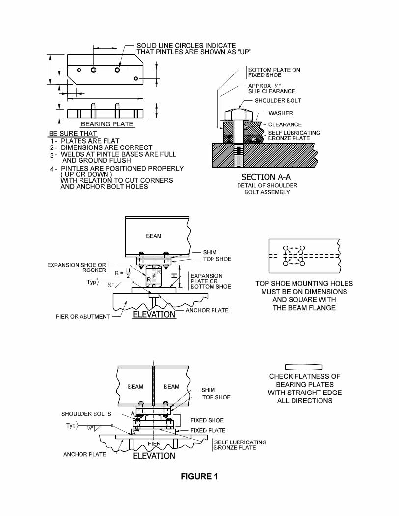
Cross Frames & Diaphragms Often fabricators fit up cross frames and diaphragms using “jigs” when multiple pieces are identical. This eliminates laying out each piece when fitting and speeds up the fit up process. The Inspector must check one of the first few of these cross frames or diaphragms for accuracy. He should also check a few after they have been welded to see that the welding has not distorted the member. Cross frames and diaphragms normally do not go into shop assembly with girders or beams therefore must be fabricated accurately with the holes punched or drilled full size. In some instances on curved bridges the specifications call for full assembly. This means putting the girders in position with cross frames or diaphragms and reaming the connections while assembled. The cross frames or diaphragms then may have the holes punched or drilled undersize then reamed full sized while in assembly. In these cases the fabricator should have some type of match marking system shown on the shop drawings to locate these members when they are reassembled in the field. Bearing Material & Expansion Material Bearing material must be checked as it is fit up to see that parts assembled requiring “mill to bear” fit up have no gaps exceeding those allowed by the BWC (3.5.1.9) and those requiring “tight fit” have no gaps exceeding those allowed by the BWC (3.5.1.10). The Inspector should also take a close look at any weld joints with beveled edges to see that the proper joint alignment is maintained after fit up. If the fabricator identifies the weld joint by marking it with the welding symbol this must also be checked closely. Bearings that are made with high strength steel usually require special welding procedures. The inspection of bearings includes: 1. An accurate dimensional check of all parts 2. Flatness of bearing plates 3. Squareness of mounting-hole locations 4. Flush surfaces at pintle welded bases 5. Pintles located correctly in plates, especially where plate locations can not be
reversed 6. Bearing surfaces carefully and correctly machined 7. Bearing edges free from burrs and over-welds 8. Proper lengths of cap screws and shoulder bolts 9. Proper clearance of self-lubricating bearing plates 10. Proper cleaning, painting and coating of machined surfaces Various details showing bearings are presented in Figure 1.

(This page Intentionally Blank)
21
7. WELDING The Standard Specifications and additional provisions in our contracts provide that welding should conform to the BWC. Welding Procedures (WPS) Qualification of welding procedure specifications (WPS) should be established in accordance with the BWC before welding begins. Central Office Division of Construction Management reviews the fabricator’s proposed WPS and either approves or denies the WPS. The fabricator may be required to run additional tests to qualify WPS for the contract. WPS qualified by tests in accordance with the BWC should be recorded on the Procedure Qualification Record (PQR) form listed in the appendix in the BWC. The test should be witnessed by another party other than the fabricator such as a DOT or independent inspection agency and that party should sign and date the PQR. This PQR should then be submitted to the Engineer for approval and is used to qualify the WPS used by the fabricator. All WPS submitted by the fabricator for use on INDOT contracts should include the qualifying PQR number and appropriate information from the PQR such as maximum heat input of the test. This is important when reviewing the WPS for approval. WPS qualified for use on INDOT contracts should remain in effect for periods shown in section 5 of the BWC. INDOT should accept a WPS from the fabricator that was qualified for contracts or projects other than INDOT provided it meets the requirements of the BWC. A form for submitting WPS is shown in the appendix of the BWC and the fabricator should use this form so that all pertinent data can be recorded. Welders Qualification All welders and tackers should be certified in accordance with the BWC Section 5, Qualification. The Fabricator keeps a list and updates that list. Our Inspector is furnished a copy and is to review it periodically. The Inspector should take this information and record it on the “List of Approved Welders, Welding Operators, and Tackers” form contained in the Appendix of this manual. This qualification should be established before welding begins and is effective for an indefinite period unless the Inspector has reason to disqualify the welder from welding on INDOT contracts. The fabricator should establish and maintain a record of approved welders in each plant to simplify the administrative work and documentary evidence of compliance with the specifications in respect to the submission of reports on qualification of welders. The Inspector is allowed to review and have a copy of this record. INDOT accepts welder qualifications from the fabricator that were qualified for contracts and projects other than INDOT contracts, provided the qualifications meet the requirements of the BWC. A PQR performed by the fabricator should also serve as welder or welding operator qualification. No further documentation as to the qualification of welding operators is needed to submit for each and every project, except a notation at the beginning of the inspector’s IC-701 progress report that welders will be referred to by the stamp number as listed on their qualification certificate in the District Office control file.
22
Any question of the qualification of a welder by a representative of INDOT as to class of electrode, position of welding, procedure or quality of workmanship, should be cause for removing the welder from INDOT projects until the qualification is verified. If necessary, a request for re-qualification test of any welder should be the right of the Engineer. Splicing Web and Flange Plates on Girders This is a butt weld either for additional length or transition of plate thickness. The joint preparation for this weld should be specified in detail on the plans. Usually this is a submerged arc procedure (SAW). Recently the use of Electro Slag Welding (ESW) has been permitted for flange butt welding. This process was banned for years but now has been brought back after much research and refinement of the process. ESW requires special equipment and procedures. The Inspector should check closely that any flange butts with this process is done in strict accordance with the qualified WPS. The Inspector must check (using approved welding procedures) to see that preheating, amperage, voltage, speed and other welding parameters conform to the approved WPS within BWC allowable variations. The Inspector should also check to see that wire and flux have been maintained by the fabricator in accordance with the BWC. Butt welded joints must be carefully fitted so that the plates to be joined are aligned straight and not crooked. This may be checked with a string line. The welds must be extended beyond the plates to be joined by means of run-off tabs to ensure sound welds at the termination. This is a task that the fabricator’s QC person should perform. Extensions (run-off tabs) should be removed upon completion and cooling of the weld and the ends of the weld ground smooth and flush with the edges of the abutting parts. The inspector must check this grinding carefully. If flame cutting gouges occur in the removal of the run-off plates, the voids must be filled with weld metal before grinding using approved WPS. Welds on web or flange plates of uniform thickness should be ground flush on both sides. Splices joining non-uniform plate thicknesses should be ground flush on the aligned side and the transition side ground to merge smoothly with the plate. Special care should be taken to insure that plates are not ground below the ordered thickness. Small localized reductions in section thickness are permitted, provided the reduction is not more than allowed in the BWC.
23
Flange to Web Welds on Girders Girder flange to web welding is performed two ways. One procedure is where the fabricator fits (tack welds) the flanges to the web and positions and girder 45 degrees from perpendicular, for a flat position submerged are weld. The other procedure is where the girder web plate is in the horizontal plane and both, the top and bottom flanges are welded simultaneously. It is important that the girders are blocked into position before welding is started. It is the fabricators responsibility to see that the girders are position so that camber is not lost or gained while welding. This helps prevent heating the girder to adjust the camber after welding is completed. Run-off tabs or other means may be used for flange to web fillet welds in order to obtain a full sized weld at the termination. Most fabricators make the girders several inches longer than the detailed length. This permits the welding operator to stop short of the end of the girder just beyond the predetermined girder end therefore eliminating the use of added run-off tabs. Tack welds are usually placed only on one side of the girder prior to welding. The fabricator generally turns the girder over and welds the other side first. After this is done the girder is turned over and the tacks are removed. The tacks do not have to be completely removed because the remaining tacks after grinding are remelted in the final weld. Not all fabricators follow this method and some may choose to weld over the tack welds. In this case the fabricator should take care to remove all tack weld slag prior to making the final weld. The faying surfaces (area mating two components) must have all mill scale removed. Edge preparation must be checked. If the plans call for full penetration welds, the bevel must be checked. The inspector must check the WPS for preheating requirements before welding is started. Where preheating is required, the inspector must see that it is done and should check it using a calibrated thermometer or other temperature measuring devices such as temperature sticks. The size of the fillet weld must be checked frequently as well as welding conformance with the fabricator’s approved procedures. After all four (4) fillet flange to web welds have been completed and allowed to cool, the individual camber should be checked by the fabricator to see if any change has occurred. Changes in blocking and welding sequence can be made at this time if necessary. The welding operator should keep the slag and loose flux removed from the finished weld while the welding is in progress. Most flange to web fillet welds today are made in a single pass. The slag from these welds can easily be removed from the surface of the weld if the weld is made correctly. Full penetration groove welds often require multiple passes and the Inspector should check to see that the slag is being removed after each pass. Slag remaining on the weld after a pass can be trapped in the succeeding pass causing for a weld defect. Stiffener Welding The Inspector must check the fit-up of the stiffeners. Tack welds should be staggered on opposite sides of the stiffeners, except at the ends. Most shops use submerged arc process for
24
welding stiffeners. Most stiffeners to web welds stop short of the end of the stiffener. This should be shown on the shop drawings and/or the WPS. The inspector should watch this closely because welds beyond these limits must be removed and methods to remove these welds, normally by grinding, can cause craters in the girder web requiring additional repair. The Inspector should watch for cracks in craters at the ends of the fillet welds on stiffeners. Latest research on stiffener welding indicates that fatigue failures occur at the termination of the fillet welds. If a crack, no matter how large or how small, is found in the “web plate” at the end of the fillet weld on stiffeners, call the fabricator’s attention to this immediately. The Inspector must report this condition and the method of correction in the weekly report and should not accept the girder until it has been satisfactorily repaired and a passing MT test is obtained. Cracks in any weld must be examined closely by both the Inspector and fabricator. The inspector should watch the welding process that has produced a crack to see that the WPS is being followed. It could be that the WPS is not one that will produce a good weld and it may need to be disqualified. Shear Stud Welding Shear stud welding should be performed by welders and procedures qualified in accordance with the BWC. Many DOTs today do not allow shear studs to be welded to the top flanges of the girders in the shop because of OSHA requirements. Cross Frames and Diaphragms Welds on cross frames and diaphragms should be done using approved WPS. These WPS are usually fillet welds made using stick welding (SMAW) or flux cored wire (FCAW) welds. The inspector should check to see that the fabricator is following the approved weld procedures. Welding Inspection General Section 3 of BWC specifies requirements for the preparation of material for welding, the assembly of parts, the procedures for welding, and workmanship. During preparation and assembly of parts for welding, the fabricator QC individual should give special attention to the following. The Inspector monitors this along with the QC. 1. Check each part for conformance with section 3 of the BWC. 2. Plate edges that have been flame cut are visually examined for cracks or
laminations. 3. The dimensions and form of edge preparation on butt joints are measured for
conformance with drawings. 4. Alignment and fitting of parts are checked for conformance with section 3 of the
BWC. Misalignment between abutting parts should be corrected.
25
5. Details such as stiffeners or cover plates are checked to see that they are located in accordance with drawings.
6. Whenever possible, one member of a joint should be free to move longitudinally to
allow for shrinkage in weld metal. 7. Requirements for all welding processes are in accordance with the BWC. 8. Observe the welding procedures frequently to see that no unauthorized changes have
been made, and that no welder is assigned for work for which he is not qualified. 9. Particular attention is given to the use of preheating specified in the BWC.
Preheating retards the cooling of the weld, and can be effective only when properly done. Heat applied to the joint should be uniformly distributed so as to avoid over-heating any area. The joint should be kept at the specified temperature until welding is started. As the welding progresses, the surfaces of the parts within (3) inches of the point of welding, both laterally and in advance of the welding, should be at or above the specified preheat temperature. When a minimum interpass temperature is specified, the weld joint, between passes, should not be allowed to cool below that temperature. The fabricator should be required to use temperature indication crayons or some other positive means for measuring temperature.
10. Maintain a close check on the length of time that low hydrogen electrodes issued to
welders are being exposed to air before use. The restrictions of this exposure time are specified in the BWC and should be included in the fabricators quality control plan or standard operating procedures.
11. The quality of workmanship of each welder should be checked continuously by
visual inspection as the welding progresses. If the quality of work of any welder or welding operator appears to be below the requirements of the BWC, the Inspector may, require a retest of his qualifications.
12. If any welder or welding operator continues to do substandard work under the
BWC, he should be prohibited from welding until such time as his work has improved enough to meet specifications.

26
(This page Intentionally Blank)
27
8. NON-DESTRUCTIVE WELD TESTING Non-destructive testing of weldments is the responsibility of the fabricator and is witnessed by the Inspector. The fabricator supplies all equipment, personnel and test methods to perform the nondestructive testing. Section 6 of the BWC provides additional information. Radiographic Inspections (RT) Radiography is a non-destructive test method, the purpose of which is to show defects and discontinuities of the interior of welds under examination. A good x-ray will show the presence or absence of a defect in a weld, and if present, its size, shape and location are clearly defined. It is absolutely necessary to have a satisfactory radiograph before a sound interpretation of the film can be made. Radiographic methods should produce films having a sensitivity of 2%. When sensitivity is spoken of, it is considered to mean the least percent of weld thickness differences which can be detected visually on a radiograph. The detection of such a thickness difference by the observer is a function of the sharpness of the outline and the contrast of the image against the film background. For the detection of these two qualities in a radiograph, a gage known as a pentameter is used. This consists of a thin strip of metal equal in density to the weld metal. Its thickness is equal to or less than 2% of the weld thickness. The Inspector will examine the welds to be radiographed. If visual inspection reveals irregularities that will have to be repaired with filler metal, radiographic inspection must not be performed before the repaires have been made. All welded joints which are to be radiographed should be ground smooth four sides before being radiographed. The grinding should remove all weld ripples and surface irregularities so the weld surface will merge into the plate surface to such a degree that the resulting radiographic contrast will not mask objectionable defects. The fabricator’s obligations and the Inspector’s duties are clearly spelled out in Section 6 of the BWC. The Inspector should ensure that the x-rays are being taken by certified AWS personnel. A copy of the credentials should be obtained and placed in the project file. The Inspector should maintain a record of where x-rays have been taken to ensure that no weld is omitted or duplicated. The Inspector should review the film for conformance as well as making sure it has been properly identified. The radiograph reports should correspond with the film. The Inspector should obtain a copy of these reports and include them in the final fabrication report.
28
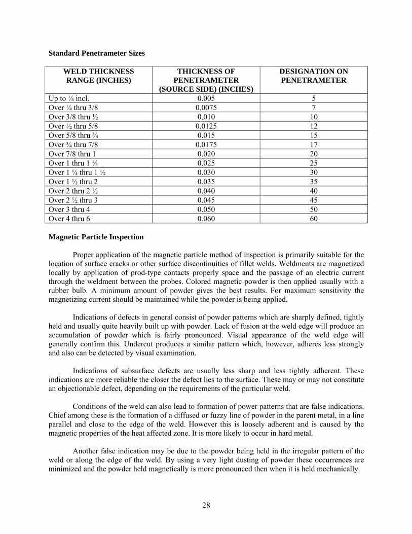
Standard Penetrameter Sizes
WELD THICKNESS RANGE (INCHES)
THICKNESS OF PENETRAMETER
(SOURCE SIDE) (INCHES)
DESIGNATION ON PENETRAMETER
Up to ¼ incl. 0.005 5 Over ¼ thru 3/8 0.0075 7 Over 3/8 thru ½ 0.010 10 Over ½ thru 5/8 0.0125 12 Over 5/8 thru ¾ 0.015 15 Over ¾ thru 7/8 0.0175 17 Over 7/8 thru 1 0.020 20 Over 1 thru 1 ¼ 0.025 25 Over 1 ¼ thru 1 ½ 0.030 30 Over 1 ½ thru 2 0.035 35 Over 2 thru 2 ½ 0.040 40 Over 2 ½ thru 3 0.045 45 Over 3 thru 4 0.050 50 Over 4 thru 6 0.060 60 Magnetic Particle Inspection Proper application of the magnetic particle method of inspection is primarily suitable for the location of surface cracks or other surface discontinuities of fillet welds. Weldments are magnetized locally by application of prod-type contacts properly space and the passage of an electric current through the weldment between the probes. Colored magnetic powder is then applied usually with a rubber bulb. A minimum amount of powder gives the best results. For maximum sensitivity the magnetizing current should be maintained while the powder is being applied. Indications of defects in general consist of powder patterns which are sharply defined, tightly held and usually quite heavily built up with powder. Lack of fusion at the weld edge will produce an accumulation of powder which is fairly pronounced. Visual appearance of the weld edge will generally confirm this. Undercut produces a similar pattern which, however, adheres less strongly and also can be detected by visual examination. Indications of subsurface defects are usually less sharp and less tightly adherent. These indications are more reliable the closer the defect lies to the surface. These may or may not constitute an objectionable defect, depending on the requirements of the particular weld. Conditions of the weld can also lead to formation of power patterns that are false indications. Chief among these is the formation of a diffused or fuzzy line of powder in the parent metal, in a line parallel and close to the edge of the weld. However this is loosely adherent and is caused by the magnetic properties of the heat affected zone. It is more likely to occur in hard metal. Another false indication may be due to the powder being held in the irregular pattern of the weld or along the edge of the weld. By using a very light dusting of powder these occurrences are minimized and the powder held magnetically is more pronounced then when it is held mechanically.
29
When required, magnetic particle inspection should be performed by a Level 1, 2, or 3 Certified CWI. The Inspector should obtain a copy of their credentials and place this copy in the file. The Inspector should maintain a record of where the testing was performed to ensure that nothing was omitted or duplicated. In all cases, the tests should be performed in the presence of the Inspector. The Inspector will witness the test being performed. The Certified CWI will interpret the patterns and accept or reject the welds. If the Inspector disagrees with the Certified CWI, they should discuss and involve outside parties if necessary. The Inspector should obtain a copy of the final report and include this in the final fabrication report. These tests should be made in conformance with the BWC. Dye Penetrate Inspection (PT) Dye penetrate inspection is a three stage operation. The part is sprayed with a cleaner to remove all oil, grease and foreign materials. It is then sprayed with the dye penetrate, a specially prepared penetrating oil to which a visible dye material has been added. This solution penetrates surface cracks and irregularities. The excess penetrate is removed. The part is then sprayed or brushed with the developer. This may be a chalky substance that dries on contact. The substance is stained by the dye, which rises by capillary action from flaws in the surface and marks them clearly in red. These tests should be made in conformance with the BWC section 6.7.7 and ASTM E165. Ultrasonic Testing (UT) Only personnel qualified in accordance with the BWC should perform ultrasonic testing. The Inspector should obtain a copy of their credentials and place this copy in the file. The Inspector should maintain a record of where the testing was performed to ensure that nothing was omitted or duplicated. The Inspector will become familiar with reading the equipment screen when observing this process. The Inspector also should be able to read and interpret the fabricator’s inspection report and to locate the defects on the material from the report. The Inspector should witness this test. The Certified CWI interprets the patterns and accepts or rejects the welds. If the Inspector disagrees with the Certified CWI, they should discuss and involve outside parties if necessary. The Inspector should obtain a copy of the final report and include this in the final fabrication report. These tests should be made in conformance with the BWC.

30
(This page Intentionally Blank)
31
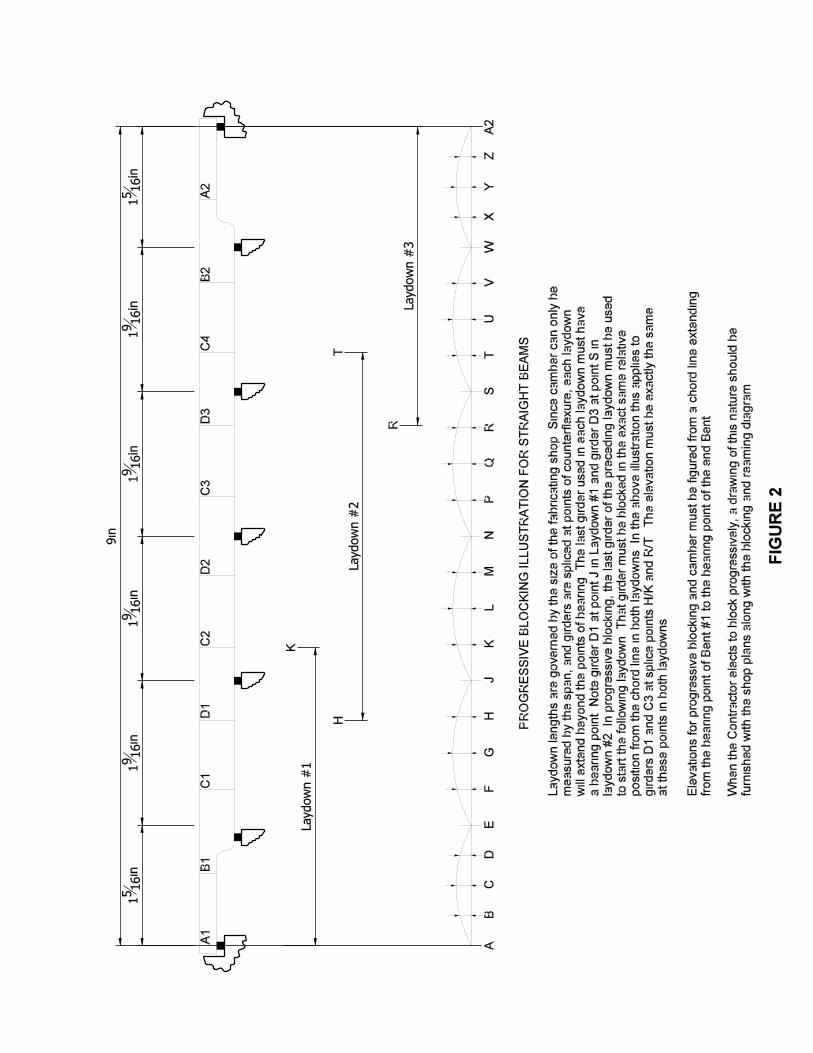
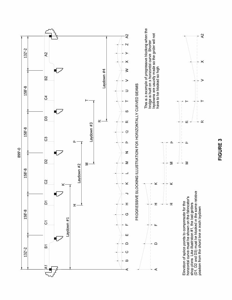
9. ASSEMBLE & REAM The last operation prior to cleaning and painting is shop assembly of the girders and beams so that splices can be reamed or drilled to final size. Blocking and Camber The construction plans and the shop plans show blocking dimensions for positioning the beams or girders for splice reaming and drilling. After beams have been cambered or girders have been welded, they must meet BWC camber and straightness tolerance before the ends are trimmed or the web splice holes are sub-drilled. Unless otherwise specified, blocking is performed with beams or girders assembled in accordance with the “No Load Camber and Reaming Diagram”. When the contractor has assembled a line, he should call the Inspector for the camber and blocking check. The laydown (assembly) check is performed by the fabricator’s QC. The approved shop drawings should detail required camber as well as reference the BWC 3.5.1.3. The Inspector checks the laydown and reports any discrepancies to the fabricator’s QC. It is the fabricator’s QC who instructs the fabrication personnel on when to proceed with drilling the laydown. Before beginning to check the blocking and camber of any lay down, the Inspector must first examine the splices. The clearance between the ends of the beams should not exceed the specifications or AWS tolerances. At this stage the assembly is usually held in position with only the web splice plates. The flange splice plates are usually only held in position with “C” clamps so the holes can be drilled full size. The web splice plates must be bolted tight so the opposing web ends are drawn to perfect alignment and should not shift when the flange splice holes are drilled. When necessary to measure from a flange splice plate, the thickness of the splice plate must be added to the elevation readings. Also readings from girder flange plates of variable thickness must be compensated. After the blocking has been found satisfactory, the fabricator’s QC performs the following. Measure camber by the span (bearing to bearing). In checking the center to center of bearings, it is well to keep in mind that this dimension along the line of beams per shop drawings does not always coincide with the center line given by the field erection drawings. When the blocking and camber is found satisfactory, the fabricator’s QC approves the lay down for reaming and drilling. (The Inspector witnesses the camber and blocking check, but does not okay the laydown for drilling.) A laydown assembly report should be obtained and included in the final fabrication report. The shop plans should show a plan of match marking for all drilled and reamed splices. All splice plates must be removed, cleaned and deburred after reaming and drilling. Splice plates should not extend beyond the ends of beams or girders after bolting for shipment without prior written approval from the Department. Long structures often require progressive blocking. In such instance, the fabricator is required to submit his progressive blocking plan to the Central Office Division of Construction Management for approval before such blocking can be permitted. Examples of progressive blocking schemes are presented in Figure 2 and Figure 3.

32
(This page Intentionally Blank)

(This page Intentionally Blank)

(This page Intentionally Blank)
33
10. CLEANING & PAINTING Cleaning The general requirements for cleaning steel are set out in the Standard Specifications. The Inspector must be thoroughly familiar with this specification and see that the surfaces are cleaned in accordance. The inspector should also be familiar with the SSPC specification for terms, definitions, processes, and materials used in cleaning and painting. Cleaning is very important. Rust that is not removed will eat through the paint. Paint applied over mill scale will blister and pop off. Since the degree of surface preparation cannot be readily verified after painting, inspection of the prepared surface must be performed before paint is applied. Cleaning of beams and girders must be inspected while the painters are preparing the surface for the paint application. Any mill scale still adhering after blasting must be removed. Gouges and welding defects not noticed before should be readily apparent. These defects must be repaired before paint is applied. After blasting and prior to the application of paint, the QC checks the surface profile of the blasted steel. The Inspector should witness this test being performed. The results should be discussed and agreed upon before painting. Steel which is not to be painted is noted on the shop drawings (such as A 709 GR. 50W), must be blast cleaned free of mill scale and discolored camber heated areas so the member will weather evenly). The degree and limits of blasting are listed in the Standard Specifications. Painting Before starting to paint, the Inspector obtains the batch numbers from the paint to be used. The Inspector contacts District Testing and they advise if the paint is on the approved list. Only paint that has been approved may be used. A check of the batch numbers on the containers against those listed on the lab test report must be made. If the fabricator has paint that has not been approved for use by INDOT or has its shelf life expired the following procedure for acceptance should apply: The Inspector obtains a sample of paint to be used at the earliest possible date so that no painting is done before receiving approval of the paint. The sample is submitted to the Materials and Tests Laboratory in Indianapolis accompanied by an SM-530 Sample of Material form, giving all information called for on this form. The sample should consist of one five (5) gallon unopened container of paint per the frequency manual. Under no circumstance should the inspector accept for testing, a can of paint which has been shipped or marked as “Sample “. The sample submitted for testing should be from the supply to be used. Whenever an unopened five gallon container is submitted for testing the SM – 530 should include a request that the unused portion of the sample be returned to the fabricator. Be sure that the return address is given.
34
Preparation and application of the paint should be in accordance with the Standard Specifications. Painting should also conform to instructions given on the plans, usually under General Notes. No shop painting is allowed when the steel surface or the environmental conditions are outside the limits for painting as outlined in the Standard Specifications 619 and 711. Surfaces not in contact but which will be inaccessible after assembly should be cleaned and given the complete coat system per the Standard Specifications. This specification includes the interior surfaces of abutting expansion joint sections. Machine finished surfaces for sliding contact must be coated as soon as practicable, after being accepted, with materials per the Standard Specifications. This specification includes the surfaces of semi-fixed shoes in contact with bronze plates. Magnetic instruments are used to measure dry paint film thickness (DFT). Typically the Inspectors have been using an Elcometer or Positector to check the dry mil thickness. A record of dry film thickness measurements is required on the Inspector’s daily report. When measuring dry paint thickness, the Inspector must be sure that the gage is calibrated correctly. These are delicate instruments and should be checked frequently. Another variable is the relative hardness of the paint film. Paint must be dried hard before a true thickness measurement can be obtained. At no time should the Inspector approve material for shipment before the paint has dried. The paint dry film thickness should be checked after the “dry to inspect” time has elapsed. The material should not be shipped until the “dry to handle” time has elapsed. The drying times for a paint system are usually on the manufacturer’s data sheet for the paint system. The QC maintains a record of the relative humidity, blast profile, dew point, temperature of the steel immediately prior to painting, and their values for dry film thickness. The Inspector should witness the dry film thickness values being taken by the QC and the Inspector should take a few independent measures for comparison with the QC’s readings. The Inspector should obtain a copy of this information from the QC to be included in the fabrication file.
35
11. FINAL ACCEPTANCE & SHIPPING Final inspection and acceptance should take place after all blasting and painting operations are complete. The fabricator should make available all materials to the Inspector in such a way so that the Inspector may safely inspect them. All reports by the fabricator should be complete at this time and be made available to the Inspector. The Inspector should also have completed his reports including the following 1. Daily reports detailing progression of fabrication 2. Heat number traceability reports for main members 3. Welder qualification reports. 4. Mill Test Report review for all materials. 5. Non Destructive Testing reports for welds. 6. Final acceptance reports for fabricated members. 7. Reports of assemble and reaming. 8. Correspondence reports including drawing changes, repairs, etc. 9. Paint checks including blast profile and paint thickness readings along with
environmental checks. 10. Test reports for bolts sampled and tested at the fabrication facility. The “Completed Materials Report” form contained in the Appendix of this manual should be completed after all fabrication and painting is complete. The final fabrication report packet should contain the following: 1. the Inspector’s daily reports 2. Mill Test Reports 3. UT, RT, MT Reports 4. Laydown Assembly Reports 5. Completed Materials Reports 6. Any Relative Project Correspondence Material is often stored outside after fabrication and prior to shipping. This should be done in accordance with the Standard Specifications and care should be taken not to damage the materials. Materials loaded for shipment should be checked for any rust or damage by the Inspector and should be repaired prior to shipping. Girders and beams should be loaded for shipment such that they are not subjected to bending about their weak axis (webs must be vertical) unless they are supported in such a way to prevent bending during shipment. The fabricator should submit special blocking and loading procedures to INDOT for approval if girders or beams are to be shipped in this manner.

36
(This page Intentionally Blank)

Appendix

(This page Intentionally Blank)
A-1
SUGGESTED PREFABRICATION MEETING AGENDA ITEMS
o Date, Location, and Attendees of Meeting o Inspector Office Space and Equipment Requirements o Fabrication Schedule and Advance Notification of QA inspector o Line of Communication between Fabricator and Inspector o Procedure for and progress of Shop Drawing and Welding Procedure Approval, Revisions,
and Distribution. Also supply and sampling of bolts, paint, and other materials (if applicable) o Fabricator Certification o Welding Procedures o Welder Qualifications o Inspection Personnel Qualifications o Production and Inspection Equipment Calibration o Material Test Reports and Certifications o Material Inventory and Purchases. Any special grades of material? o Inspection of Material upon arrival at Facility o Plan for Nonconforming Material o Plan for Acceptance and Testing of Outsourced Materials or Fabrications o Identification (traceability) of Materials through the Fabrication o Storage of Raw Materials o Preparation and Layout of Material for Fabrication o Project specific areas of concern for fabrication and inspection. Project details, requirements,
or processes that have caused prior difficulties. o Fit-up of Materials Prior to Cutting, Drilling, Punching, Welding o Assembly for Reaming o Welding. (Joint preparation, weld metal, preheating & flux temperatures) o Cambering and Heat Straightening o Non-destructive Testing and Procedures o Deburring, Cleaning, and Painting o Presentation of Materials for Acceptance o Payment o Storage of Materials after Fabrication o Method of Shipping and Tentative Dates o Final Acceptance of Materials for Shipment o Open Discussion
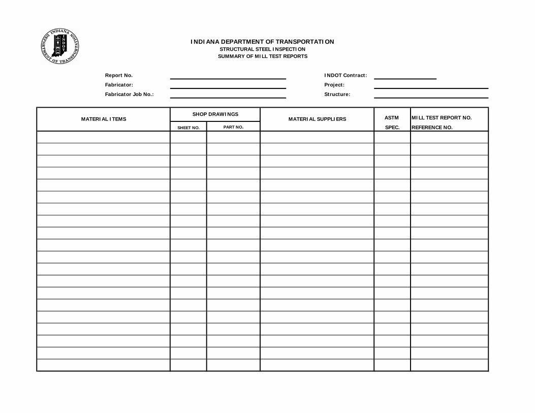
Report No. INDOT Contract:
Fabricator: Project:
Fabricator Job No.: Structure:
ASTM
SHEET NO. PART NO. SPEC. REFERENCE NO.
MILL TEST REPORT NO.MATERIAL SUPPLIERSSHOP DRAWINGS
INDIANA DEPARTMENT OF TRANSPORTATIONSTRUCTURAL STEEL INSPECTION
SUMMARY OF MILL TEST REPORTS
MATERIAL ITEMS
Report No.: INDOT Contract:
Week Ending: Project:
Fabricator: Structure:
Fabricator Job No.: Inspector:
Date
INDIANA DEPARTMENT OF TRANSPORTATIONSTRUCTURAL STEEL INSPECTION
WEEKLY REPORT
Fabricator: Date:
MATERIAL POSITIONS QUAL. GRADES QUALIFIED REPORT
NAME IDENT. PROCESS QUAL DATE
INDIANA DEPARTMENT OF TRANSPORTATION
LIST OF APPROVED WELDERS, WELDING OPERATORS, & TACKERSSTRUCTURAL STEEL INSPECTION
Report No.: INDOT Contract:
Fabricator: Project:
Fabricator Job No.: Structure:
The following items along with their mill test reports have be made available to INDOT for inspection.
Number
Req'd. Accepted Rejected
The above listed parts have been inspected and either approved for shipment, or have been rejected as indicated. The parts are subject to the final approval or rejection of the Project Engineer in charge of the erection of the parts inthe field. The certified mill test reports have also been checked and approved as indicated in the shop inspectionreport for this contract.
Fabricator Representative Date
INDOT Representative Date
INDIANA DEPARTMENT OF TRANSPORTATION
Number of PiecesPart or Material Description Part Number Remarks
STRUCTURAL STEEL INSPECTIONCOMPLETED MATERIALS REPORT