india journalcigreindia.org/cigre january 2017.pdfcigre india journal volume 6, no. 1 january 2017...
TRANSCRIPT

JournalINDIA
Vol. 6, No. 1 - January 2017 (Half Yearly Journal)
ciINDIA
ISSN : 2250-0081 (Print)ISSN : 2250-009X (Online)
Inaugural Session of 46 CIGRE Session, the Bi-annual Technical Conclave held in Paris from 21st to 26 August 2016


CIGRE IndIa JouRnalVolume 6, No. 1 January 2017
Disclaimer : The statements and opinions expressed in this journal are that of the individual authors only and not necessarily those of CIGRE - India.
Editorial Advisory Board
• I.S.Jha,CMD,POWERGRID&President,CIGREIndia• R.P.Sasmal,Director,POWERGRID&ChairmanTech,
CIGREIndia• N.N.Misra,FormerDirector(Opn.),NTPC&Vice-Chairman
(Tech.)CIGREIndia• AmitabhMathur,Director,BHEL&VicePresident,CIGRE
India• K.K.Sharma,Director,NTPC,&VicePresident,CIGRE
India• MataPrasad,FounderPresidentCIGREIndia• Prof.S.C.Srivastava,Deptt.ofElect.Engg.IIT,Kanpur• PhilippeAdam,SecretaryGeneral,CIGREHQ,Paris• Dr.MohinderS.Sachdev,University ofSaskatchewan,
Canada
CONTENTSPage No
Editor’s Note 2Articles• TransmissionandDistributionIntegratedAnalysisandEvaluationSystemforDistributedGeneration –J. Suh, S.Yoon and G. Jang 3
• IntegratedRoleofDielectricFluidsinPowerTransformersandShuntReactors–K. Baburao, Nalin Nanavati and P.N. Narayanan 9
• OperationalExperiencein1200kVNationalTestStation(UHVAC),India–I.S. Jha, B.N. De. Bhowmick, S.B.R. Rao, Dhyeya. R. Shah, Rachit Srivastava, R.K. Singh, S.V. Kulkarni and Santosh Kumar 15
• EnsuringHighQualityInsulationSystemofLargeMotors–Design&TestingRequirements–A.K. Gupta, D.K. Chaturvedi and P.K. Basu 26
Activity of the Society 47
• CIGREIndiaSession2016–NationalConferenceonGlobalTrendsandInnovationsinDevelopment ofPowerSector,28-29July2016,NewDelhi 32
• CIGRESession2016,21st–26thAugust2016,atParis–AReportbyCIGREIndia 42Brief About CIGRE India 49
CIGRE Members from India in 2016 51
List of Papers Accepted from India for CIGRE session 2016 at Paris from 21-26 August 2016 58
Technical Data 62
News 64
• Dr.KonstantinO.Papailiou,CEO,PFISTERERHoldingAGandChairmanofCIGRESCB2onOverheadLines
• IvanDeMesmaeker,Swedan,FormerChairmanCIGRESCB5onProtection&Automation
Editors• V.K. Kanjlia, Secretary & Treasurer, CIGRE India &
Secretary,CBIP• P.P.Wahi,DirectorInchargeCIGREIndia&CBIPAssociate Editor• VishanDutt,ChiefManager,CIGREIndia&CBIP
All communications to be addressed to:TheSecretary&TreasurerCIGREIndiaCBIPBuilding,MalchaMargChanakyapuri,NewDelhi-110021
Subscription Information 2017/ (2issues)Institutionalsubscription(Print&Online) : Rs.900/US$75Institutionalsubscription(Onlineonly) : Rs.600/US$50Institutionalsubscription(Printonly) : Rs.600/US$50Subscriptionfor10Years(PrintOnly) : Rs.5,000Subscriptionfor10Years(Online) : Rs.5,000Subscriptionfor10Years(Print&Online) : Rs.8,000

Volume 6 v No. 1 v January 2017
V.K. KanjliaSecretary&Treasurer
CIGREIndia
2
EdItoR’s notECIGREtheInternationalCouncilonLargeElectricSystemsfoundedin1921,isleadingworldwideOrganization onElectric PowerSystems, covering technical, economic, environmental,organisationalandregulatoryaspects.Itdealswithallthemainthemesofelectricity.CIGREistheuniqueworldwideorganizationofitskind-14,000equivalentmembersinaround90countries.CIGREisfocusedonpracticaltechnicalapplications.ThemainaimofCIGREistofacilitateanddeveloptheexchangeofengineeringknowledgeandinformation,betweenengineeringpersonnelandtechnicalspecialists inallcountriesasregardsgenerationandhighvoltagetransmissionofelectricity.CIGREachievesitsobjectivethroughthe16Study
Committees,eachconsistingofabout24membersfromdifferentcountries.ItisamatterofprideforIndiathatwearerepresentinginallthe16StudyCommitteeofCIGRE.
BesidesNationalCommitteesinabout60CountriesCIGREhasalsoconstituteditsregionalchapters in theworld. The chapter created forAsia is namedasCIGRE-AORC (AsiaOceansRegionalCouncil).CIGRE-AORCisaforumforsharingexperienceandknowledgeregardingpertinenttechnicalissuesparticularlythoseaffectingpowersystemsintheAsia-
OceanaRegion.ThecountriesfromAsiaOceanaRegion,whoareassociatedwiththeforumareAustralia,China,Cambodia,GulfCooperativeCouncil,HongKong,India,Indonesia,Iran,Jordan,Japan,Korea,Malaysia,NewZealand,TaiwanandThailand.
ItisamatterofgreathonorforIndiathatCIGREAORChasapprovedthenameofIndiafortheChairmanshipofCIGREAORCfornexttwoyearsfrom2016-18.Dr.SubirSen,ED,POWERGRIDhastakenoverasChairmanandShriP.P.Wahi,asSecretaryofCIGREAORCfortwoyearduringthelastmeetingofCIGREAORCheldatParison24thAugust2016.
CIGRE(India)wassetupassocietyintheyear1991withCentralBoardofIrrigation&Power(CBI&P),MalchaMarg,Chanakyapuri,NewDelhiasitssecretariat.ItfunctionsastheNationalCommittee,i.e.,CIGRE(India)forCIGREHQ(Paris).TheCIGRE(India)coordinatesinterestofIndianmembers;organisesNationalStudyCommittee(NSC)meetings.ItrecommendsappropriatepersonsforCIGREStudyCommittees.TheNationalrepresentativesareinstrumentalinprovidingfeedbacktoCIGREStudyCommitteesatParis.
Theaimsandobjectivesforwhichthecommittee,i.e.,CIGRE(India),isconstituted,istoimplementandpromoteobjectivesoftheInternationalCouncilonLargeElectricSystems(CIGRE)andaccelerateitsactivities,whichincludethe interchangeof technicalknowledgeand informationbetweenall countries in thegeneralfieldsofelectricitygenerationtransmissionathighvoltageanddistributionetc.
All-outeffortsarebeingmadetoincreasetheCIGREmembershipandactivitiesinIndia.FiveInternationalConferenceswithparticipationofabout300ineachoftheconferencewereorganizedbyCIGREIndiaintheyear2015-16andthemembershiphasalsobeenincreasedfrom250in2015to611intheyear2016.TherewasexcellentparticipationfromIndiainCIGREsession2016atParis.Total18paperswerepresentedandmorethan100officersfromIndiaincludingCEOs&Sr.OfficersfromvariousPSUs,StateElectricityCorporationandvariousRegulatorycommissionsparticipatedinCIGREsession2016.ThisissuecoversthereportontheparticipationofIndiainCIGREsession2016atParisbesidesinformativeandusefultechnicalarticlesandstatisticaldataonthesubject.
WearebringoutthisJournalonhalfyearlybasis.ThelastissuewaspublishedinthemonthofJuly2016.IamthankfultotheGoverningCouncilandtheTechnicalCommitteeofCIGREIndiafortheirvaluabletimeandguidance,butforwhich,itwouldnothavebeenpossibletoachievetheabovesignificantprogress,appreciatedbyCIGREHQParis.
IamalsothankfultoalltheseniorexpertsfromIndiaandabroadandalsotooneandallwhohavesupportedinthepasttorealizethegoalsetforthforCIGREIndiaandexpectthesimilarsupportinfuturetoo.
V.K. Kanjlia
Secretary & Treasurer CIGRE India

Volume 6 v No. 1 v January 20173
tRansmIssIon and dIstRIbutIon IntEGRatEd analysIs and EvaluatIon systEm foR
dIstRIbutEd GEnERatIon
J. Suh, S.Yoon and G. JangKorea University, Korea
ABSTRACT
As the amount of distributed generation supplied to distribution systems has expanded, neighbouring distribution systems or even transmission systems have been more affected according to penetration of distributed generation. However, until now, power system analysis has been conducted separately for the transmission system and distribution system. This way of analysis has had no problem in the existing power systems. However, with the rising DG connection in the distribution system, the need to reflect mutual interaction has elevated and the separated method became unable to do it properly. Transmission and distribution integrated analysis aims to enabling mutual interaction analysis. In this paper, a new methodology to evaluate the effect of distributed generation in the integrated transmission and distribution systems using on-line data. And by simulating mutual interaction, which could not be observed in previous system, case study results shows the need for transmission and distribution integrated systems with distributed generation.
Keywords : DG, Distribution. PSS/E, SCADA, SOMAS, DAS, Transmission
1. INTRODuCTIONRecentlyasdistributedgeneration(DG)hasincreased,the distributed power generation has increasinglyaffected power systems. Large-scale DGs indistributionsystemcanaffecttransmissionandotheradjacentdistributionsystem.Howeverthemonitoring,analysis and evaluation associated with DG havebeenperformedseparatelyuntilnow.Inthisseparatemethod,DGcouldbeconnectedandoperatedtolocalpowersystemwithoutconsideringitseffectonotherdistribution feeder and transmission system. Thispaper presents a newmethodology to evaluate theeffect ofDGand recommend the optimal operationofDGintheintegratedtransmissionanddistributionsystems. Inorder toanalyzetheeffectofDGin theon-line environment, transmission and distributionintegrated system is connected to distributionautomationsystem(DAS)andsupervisorycontrolanddata acquisition (SCADA).When Transmission anddistributionintegratedsystemanalyzeDGconnectedpower system, both SCADA andDAS system dateis integrated automatically. Case study, which isperformed by using the real-time data of Jeonnamregion,showseffectivenessofintegratedmethod.
2. T R A N S M I S S I O N A N D D I S T R I B u T I O N INTEGRATED SySTEM
In Korea power system, transmission system is
monitored in real-time by SCADA system. AndSubstationOperating resultsManagement System(SOMAS)recordsandprovidesthereal-timedata(Maintransformer, transmission line, breaker, etc.) of theKoreaElectricPowerCorporation(KEPCO)systemfromSCADAevery30seconds.DASmonitorsandprovidesthe operating conditions of the distribution system inreal-time[1-2]. Feeder remote terminal units,which areinstalled indistributionsystem,send thestatedataofequipmenttothemainserverviacommunicationdevice.Transmissionanddistributionsystemhadbeenanalyzedand operated separately in Korean power system.However,asinstalledDGhasincreased,thenecessityof transmissionanddistribution integratedanalysis isoccurred[3-5]. Transmission and distribution integratedsystem acquiresmonitoring data fromSOMAS andDAStoprocesstransmissionanddistributionintegratedmonitoringandanalysis.Fig.1showsthearchitectureoftransmissionanddistributionintegratedmonitoringandanalysissystem.
There are two types of transmission and distributionintegratedsystemsuchasnetworkversionandstand-alone version. In stand-alone version, operator hasto install the transmission and distribution integratedanalysisprogramtostand-alonecomputerformonitoringandanalysis.AndthisversionusesthepowersystemdatafilewhichisextractedfromDASandSOMAS.Innetworkversion,integratedseveracquireandstorepower

4 CIGRE India Journal
Volume 6 v No. 1 v January 2017
system.Inconventionalsystem,operatorevaluatetheeffect ofDGmanually before it connected[6]. And theoperatoronlyconsidertheeffectofDGondistributionlinewhichconnected toDGand they ignoreeffectofDG on transmission and other distribution system.However, in real operation,DGaffects power qualityofotherdistributionortransmissionsystem.AstheDGpenetrationincrease,thoseeffectbecomeaconsiderableprobleminKoreanpowersystem.Whensystemoperatorreceiverequest thepermissionofnewDGinstallationfromelectricitysuppliers,transmissionanddistributionintegratedmonitoring and analysis systemevaluatedtheimpactofnewDGconnectionandgivesawarningtooperatorwhenviolationofregulationispredicted.Inthispreliminaryevaluationtransmissionanddistributionintegrated analysismakesmore accurate evaluationpossible by covering the entire power system andpreviouslyinstalledDG.AndpreventtheDGinstallationwhich causes problem. This automated preliminaryevaluation process considers voltage fluctuation,short-circuitcapacity,possibilityofviolationofvoltageregulation,andcapacityregulation.
C. Determination of Area of VulnerabilityVoltagesagisoneofthemostsignificantproblemforpowersystem.Anditcancausingdamagetosensitiveequipment in power system[7]. Transmission anddistributionintegratedmonitoringandanalysissystemcandeterminetheareaofvulnerabilityforvoltagesaginentirepowersystem.Inseparatedanalysis,distributionsystemfaultcouldnotbeconsideredforareaofvulnerabilityintransmissionsystem.Howeverthosefaults,especiallyinhighDGconnectedsystem,cancause thevoltage
systemdatafromSOMASandDASautomatically.AndeveryPC,whichisconnectedinKEPCOnetwork,canruntransmissionanddistributionintegratedmonitoringandanalysisfunctionwithoutinstallationofsoftware.Byusingthisnetworkversion,systemoperatorsinregionalheadquarters can use transmission and distributionintegratedmonitoringandanalysissystemeasily.
A. Power System AnalysisTransmission and distribution integratedmonitoringandanalysissystemusesPSS/Eengineforpowerflowand fault current calculation. The system comparesautomaticallywithKoreanpowersystemregulationandgivesaviolationwarning touser.Followinganalyses,whicharehardtobeperformedwith theconventionalsystemwhich analyzes transmission and distributionseparately, can be possible in the transmission anddistributionintegratedsystem.
• Automated pre l iminary evaluat ion of DGconnection
• DGconnectionimpactonneighbouringdistributionsystemortransmissionsystem
• TransmissionsystemfaultcurrentcontributionofDGindistributionsystem
• Phase angle information for distribution systemnormallyopenswitchmovement
B. Preliminary Evaluation of DG ConnectionMainpurposeoftransmissionanddistributionintegratedmonitoring and analysis system is to analyze DGconnection impact. Before DG connection, Systemoperator have to consider theeffect ofDGonpower
Fig. 1:Systemdiagramoftransmissionanddistributionintegratedsystem
1
1. Introduction
Recently as distributed generation (DG) has increased, the distributed power
generation has increasingly affected power systems. Large-scale DGs in distribution system can affect transmission and other adjacent distribution system. However the monitoring, analysis and evaluation associated with DG have been performed separately until now. In this separate method, DG could be connected and operated to local power system without considering its effect on other distribution feeder and transmission system. This paper presents a new methodology to evaluate the effect of DG and recommend the optimal operation of DG in the integrated transmission and distribution systems. In order to analyze the effect of DG in the on-line environment, transmission and distribution integrated system is connected to distribution automation system (DAS) and supervisory control and data acquisition (SCADA). When Transmission and distribution integrated system analyze DG connected power system, both SCADA and DAS system date is integrated automatically. Case study, which is performed by using the real-time data of Jeonnam region, shows effectiveness of integrated method. 2. transmission and distribution integrated system
In Korea power system, transmission system is monitored in real-time by SCADA system. And Substation Operating results Management System (SOMAS) records and provides the real-time data (Main transformer, transmission line, breaker, etc.) of the Korea Electric Power Corporation (KEPCO) system from SCADA every 30 seconds. DAS monitors and provides the operating conditions of the distribution system in real-time [1-2]. Feeder remote terminal units, which are installed in distribution system, send the state data of equipment to the main server via communication device. Transmission and distribution system had been analyzed and operated separately in Korean power system. However, as installed DG has increased, the necessity of transmission and distribution integrated analysis is occurred [3-5]. Transmission and distribution integrated system acquires monitoring data from SOMAS and DAS to process transmission and distribution integrated monitoring and analysis. Fig. 1 shows the architecture of transmission and distribution integrated monitoring and analysis system.
Fig. 1. System diagram of transmission and distribution integrated system

5
Volume 6 v No. 1 v January 2017
Transmission and Distribution Integrated Analysis and Evaluation System for Distributed Generation
sagintransmissionsystemorotherdistributionsystem.Transmissionanddistributionintegratedmonitoringandanalysissystemusesfastmethodtodetermineanareaofvulnerability[8]andintegratedanalysisresults.Byusingintegratedanalysisforareaofvulnerabilitydetermination,unlikeconventionalsystem,areaofvulnerabilityinentirepowersystemcanbedetermined.
D. ApplicationTransmission and distribution integratedmonitoringand analysis system is used for distribution systemoptimization platform. Following applications, whicharebasedon transmissionanddistribution integratedanalysisresult,areincludedinthesystem.
• OptimalplacementofESS/FACTS
• OLTCControl
• Distributionsystemreconfiguration
Moreapplicationswillbedevelopedandappliedtothetransmissionanddistributionintegratedmonitoringandanalysissystembyfurtherstudy.
3. CASE STuDIES For thecasestudies, realdistributionnetworkdataofJeollanam-doprovinceandwholetransmissionnetworkdateoftheKEPCOsystemsareused.Thereareabout70substationsinJeollanam-doprovince.Sevenmajorsubstationsbecametargetsforcasestudysimulation.Faultcurrent,powerflow,voltagefluctuation,preliminaryevaluation ofDGare simulated.Simulations focused
on the problemswhich had not been seen throughpreviousmethodologies.Thepowerflowsimulationwasperformedinordertocomparethedifferencebetweenconventionalmethod and integratedmethod. In theanalysisforonlyonedistributionsystem,theeffectofDGinotherdistributionsystemcouldn’treflecttothepowerflow.Thismakesdifferenceoftwoanalyses.TheresultsforthefaultcurrentandvoltagefluctuationshowthattheeffectofDGswasconsideredtootherdistributionsystemandtransmissionsystem.
Simulation focused theproblemswhichhadnotbeenseen throughpreviousmethodologies todemonstratethe need for transmission and distribution integratedmonitoringandanalysissystemwhereDGinputrose.
3.1 Comparison of Power Flow Analysis ResultThesimulationwasperformedwithsametransmissionsystemdata inorder tosee thedifferencebetweenconventional method and integrated method. Inconventional transmissionmonitoring and analysissystem, effect ofDG in distribution system couldn’treflectedtotransmissionanalysisresult.Thismakesdifferenceoftwoanalysisresult.Andinconventionaldistribution analysis, substation which connectbetweendistributionsystemandtransmissionsystemisassumedasslackbus.Usuallyslackbus’svoltageisassumedas1<0°whichneglecteffectoftransmissionsystemorotherdistributionsystem.Especiallyvoltageangle difference is huge because voltage angle isrelativevalue.
Table 1 :Comparisonbetweenconventionaltransmissionanalysisandintegratedmethod
Substation Transmission and distribution integrated analysis
Conventional transmission analysis
Magnitude (P.u) Angle Magnitude (P.u) Angle
Hwasun 1.0293 -16.39 1.03 -16.54
SouthGwangju 1.0279 -17.58 1.029 -17.78
Songjung 1.0211 -15.97 1.0315 -17.13
Naju 1.0262 -16.81 1.0291 -17.2
Maewol 1.0216 -17.51 1.0223 -17.66
Hwajeong 1.0205 -17.93 1.0213 -18.09
Nogseong 1.0201 -18.03 1.0209 -18.19

6 CIGRE India Journal
Volume 6 v No. 1 v January 2017
3.2 DG impact on Neighboring Distribution System and Transmission System
The Korea Electric Power Corporation (KEPCO)conducted influenceassessmentonlyoneach feederwhen determiningDG connection.However, if largescaledistributedgenerationisconnectedindistributionsystem, other neighbouring distribution systems ortransmission systemswould have a higher risk of avoltageproblem.Previously,asthedistributionsystemwasanalyzed separately, such a problemhadneverbeenconsidered.Inthiscasestudy,theoccurrenceofavoltageprobleminneighbouringdistributionsystemsortransmissionsystemsaccordingtodistributionsystemDGconnectionissimulated.Fig.2andFig.3showthevoltageprofileofHwasunandSouthGwangjudistributionsystemregardingDGonWhasundistributionsystem.ThesimulationresultshowsthatifDGwassuppliedtothefeedersbelowHwasunsubstation,thenthefeedersbelowHwasunsubstationdidnothaveavoltageproblembutthefeedersbelowSouthGwangjusubstationcouldhaveavoltageproblemduetoDGonHwasundistributionsystem. Such a possibility has not been noticed inpreviousanalysis,demonstratingtheneedfordistributionand transmission integratedmonitoring and analysissystemforDGsupplyconsideration.
Fig. 3:VoltageprofileofSouthGwangjudistributionsystem
3.3 Phase Angle Difference at Both Ends of Normally Open Switch
Currently,KEPCO’sdistributionsystemisstructuredinconnectionwithotherfeederinthesamesubstationsorothersubstationsviathenormallyopenswitchesontheendofthedistributionline.Bycontrollingsuchaswitch,distribution systems canbemoreefficiently operatedorsupplypowerduringsystemfailureormaintenance.Butinclosingthenormallyopenswitches,thedifferenceofphaseanglesonbothoverhead transferbusesareimportant.Ifthephaseangledifferencebecomeslargerthana certain level, the switchesbecome impossibletoconnect.Throughconventionaldistributionanalysismethod, which is performed by each substationindividually,itispossibletofigureoutbothphaseanglesabovetheswitchesinsamesubstationbutimpossibletomeasurebothphaseanglesabovetheswitchesbetweendifferent substations. In transmission and distributionintegrated analysis, such switch phase angles canbemeasuredandphaseangle changesaccording todifferentDGsupplycanalsobeidentified.CasestudyisperformedbyusingtherealdataofdistributionsystemsbelowSouthGwangjuandHwajeongsubstation.Table3showsinformationofthedistributionandnormallyopenswitch.Baekundistribution feeder is belong toSouthGwangjuandDaemyungdistributionfeederisbelongtoHwajeongsubstation.Andthosetwodistributionfeederisconnectedwithnormallyopenswitchtosupplyelectricpowerinabnormalcondition.
Table 2 :Comparisonbetweenconventionaldistributionanalysisandintegratedmethod
Automatic switch number in distribution system
Transmission and distribution integrated analysis
Conventional distribution analysis
Magnitude (P.u) Angle Magnitude (P.u) Angle160028 1.025 -19.27 0.997 -0.77160029 1.025 -19.28 0.997 -0.78160030 1.024 -19.28 0.996 -0.78160031 1.023 -19.29 0.995 -0.79160032 1.021 -19.3 0.993 -0.8
5
fig. 2 Voltage profile of Hwasun distribution system
fig. 3 Voltage profile of South Gwangju distribution system
4.3 Phase angle difference at both ends of normally open switch Currently, KEPCO’s distribution system is structured in connection with other feeder in the
same substations or other substations via the normally open switches on the end of the distribution line. By controlling such a switch, distribution systems can be more efficiently operated or supply power during system failure or maintenance. But in closing the normally open switches, the difference of phase angles on both overhead transfer buses are important. If the phase angle difference becomes larger than a certain level, the switches become impossible to connect. Through conventional distribution analysis method, which is performed by each substation individually, it is possible to figure out both phase angles above the switches in same substation but impossible to measure both phase angles above the switches between different substations. In transmission and distribution integrated analysis, such switch phase angles can be measured and phase angle changes according to different DG supply can also be identified. Case study is performed by using the real data of distribution systems below South Gwangju and Hwajeong substation. Table 3 shows information of the distribution and normally open switch. Baekun distribution feeder is belong to South Gwangju and Daemyung distribution feeder is belong to Hwajeong substation. And those two distribution feeder is connected with normally open switch to supply electric power in abnormal condition.
table 3 Information of switch between two substations
Substaion 1 Bank No. Feeder name Substaion 2 Bank No. Feeder name South Gwangju 3 Baekun Hwajeong 1 Daemyung
Table 4 shows the voltages and phase angles of both switch sides when DG output and location is changed. Before DG connected, there is only slight difference exist between both
Fig. 2 :VoltageprofileofHwasundistributionsystem

7
Volume 6 v No. 1 v January 2017
Transmission and Distribution Integrated Analysis and Evaluation System for Distributed Generation
3.4 Contribution of DG to Transmission System Fault Current
InthepreviousSCADAsystem,itwasimpossibletofigureoutthefaultcurrentcontributionofDGtotransmissionsystemwhenDGisconnectedondistributionsystem.However, the transmissionanddistribution integratedmonitoringandanalysissystemmakespossibletofindoutsuch faultcurrentcontribution.Table5shows theresultofcomparingthesizesoftransmissionsystem’sfaultcurrentas27MWdistributedpowerwasconnectedtoSouthGwangjusubstationsystems.Inthiscasestudyresult,notallsubstationsshowedahugeincreaseinfaultcurrentbutfaultcurrentlargelyincreasedinsubstations,which have large amount of DG in distribution line,such as South Gwangju substations and Hwasunsubstation.
Table 5 :Faultcurrentcomparison
Substation Fault current without DG (A)
Fault current with DG (A)
Hwasun 18572.8 20033.1SouthGwangju 17437.8 19879.5Songjung 24416.4 24858.8Naju 24332.7 25626.7Maewol 17439.1 18748.6Hwajeong 17029.2 18432.7Nongseong 16969 18411.7
5. CONCLuSIONInconventionalradialdistributionsystem,thenecessityoftransmissionanddistributionintegratedanalysiswaslessthanDGconnecteddistributionsystem.However,asDGpenetrationhasincreased,DGshavealargeimpactonpowersystems.ThoseDGsmakehardtoanalysisandoperatethepowersystem,especiallyindistributionsystem.ThispaperintroducedamethodologytoevaluatetheeffectonDGs in the transmissionanddistributionintegratedsystemonSouthKorea’spowersystems.Inaddition,casesstudywhichhasbeen impossiblewiththe existing separatedmethodwas conducted.Casestudy resultsshow thenecessityandeffectivenessoftransmissionanddistributionintegratedanalysis.Moreapplicationssuchasdistributionsystemreconfiguration,optimal placement ofESS/FACTSandOLTCcontrolbased on transmission and distribution integratedanalysiswillbedevelopedbyfurtherresearch.
BIBLIOGRAPhy1. The development of optimal operating system
in distribution networks based on distributionautomation. Final Report, Korea electric powercorporation,Daejeon,Korea
2. Photovoltaics,DispersedGeneration.(2011).IEEEGuide forDesign,Operation, and Integration ofDistributedResourceIslandSystemswithElectricPowerSystems.
Table 3 :Informationofswitchbetweentwosubstations
Substation 1 Bank No. Feeder name Substation 2 Bank No. Feeder nameSouthGwangju 3 Baekun Hwajeong 1 Daemyung
Table4shows thevoltages andphaseanglesofbothswitchsideswhenDGoutputand location ischanged.BeforeDGconnected,thereisonlyslightdifferenceexistbetweenbothendsofswitch.HoweverDGoutputandlocationmakeincreaseofphasedifferencewhichinterruptthecloseofnormallyopenswitch.AsDGpenetrationhasincreaseddistributionsystemoperatorhastoconsiderthephasedifferencebetweenbothendsofnormallyopenswitchbeforeitclose.AndthiscasestudyshowstheeffectivenessofverifyingthephasedifferencechangesduetoDGoutputandlocation.
Table 4 :Phaseangledifferencebetweenbothendsofswitch
Baekun feeder Daemyung feeder DifferenceMagnitude
(P.u)Angle Magnitude
(P.u)Angle Magnitude
(P.u)Angle
WithoutDG 1.0164 -19.37 1.0062 -19.74 0.0102 0.379MWDGinSouthGwangjudistribution
1.0273 -17.62 1.0097 -18.86 0.0176 1.24
30MWDGinSouthGwangjudistribution
1.0302 -16.88 1.0112 -18.44 0.0190 1.56
9MWDGinHwajeongdistribution
1.0200 -18.48 1.0179 -17.89 0.0021 -0.59

8 CIGRE India Journal
Volume 6 v No. 1 v January 2017
Energy Conservation is the Foundation of Energy Independence
3. Song, Chong-Suk, Suh, Jae-Wan, Jang,Moon-Jong,&Jang,Gil-Soo. (2013).Developmentof aTransmission/DistributionIntegratedAnalysisHybridAlgorithmforSystemOperationPlatformIncludingDistributed Generation. Journal of the KoreanInstitute of Illuminating andElectrical InstallationEngineers,27(1),35-45.
4. Sun, HB, & Zhang, BM. (2005). Global stateestimation forwhole transmissionanddistributionnetworks.Electricpowersystemsresearch,74(2),187-195.
5. Sun,Hongbin,&Zhang,Boming.(2008).Distributedpowerflowcalculationforwholenetworksincludingtransmissionanddistribution.Paper presentedattheTransmissionandDistributionConferenceandExposition,2008.T&D.IEEE/PES.
6. Corporation,ResearchCenteroftheKoreaElectricPower. (2012). A study on the new technicalguidelines for interconnection capacity ofdistributed generations in distribution system.Daejeon:KoreaTech.
7. Goswami,AK,Gupta,CP,&Singh,GK.(2008).Areaofvulnerabilityforpredictionofvoltagesagsbyananalyticalmethodinindiandistributionsystems.PaperpresentedattheIndiaConference,2008.INDICON2008.AnnualIEEE.
8.Park,CH,&Jang,G.(2005).Fastmethodtodetermineanareaofvulnerabilityforstochasticprediction of voltage sags. IEE Proceedings-Generation,TransmissionandDistribution,152(6),819-827.
BIOGRAPhICAL DETAILS OF ThE AuThORSJaewan SuhreceivedaB.SdegreefromtheSchoolofElectricalEngineering,KoreaUniversity,in2011.HeiscurrentlypursuingPh.D.degreeatKoreaUniversity.
yoon-Sung Cho, received a Ph. D. from KoreaUniversity,Koreain2008.HeworkedaseniorengineeratLSIndustrialSystemsCo.Ltdfrom2005to2012.Heis presently anassistant professor in theDepartmentofElectricandEnergyEngineering,CatholicUniversityofDaegu.Hisresearchinterestsincludepowersystemstability analysis,modeling, andenergymanagementsystems.
Gilsoo Jang receivedhisB.S.andM.S.degree fromKoreaUniversity,Korea.HereceivedhisPh.D.degreefrom Iowa State University in 1997. He worked inElectrical andComputer EngineeringDepartment atIowaStateUniversity as aVisitingScientist for oneyearandatKoreaElectricPowerResearchInstituteasaresearcherfor2years.HeispresentlyaProfessorofSchoolofElectricalEngineeringatKoreaUniversity.Hisresearchinterestsincludepowerquality,powersystemdynamicsandcontrol.

Volume 6 v No. 1 v January 20179
IntEGRatEd RolE of dIElECtRIC fluIds In PowER tRansfoRmERs and shunt REaCtoRs
K. Baburao, Nalin Nanavati and P.N. NarayananRaj Petro Specialities Pvt. Ltd.
ABSTRACT
The earliest research on electricity began in the sixteenth century through the pioneering efforts of William Gilbert hailed as the father of ‘electricity’. Several other great scientists followed the path breaking research and worked on many areas viz., static electricity and principal of conduction, electric current, impulse, induction, electromagnetism, electric motor and their applications during the period 1660 to 1890. Over the last century and beyond the world has witnessed exponential growth in the demand for electric power since every sphere of activity is dependent on it. This has resulted in rapid development of HV, EHV, and UHV, generation, transmission and distribution systems. Further in the recent times smart power grid systems have emerged revolutionizing entire power sector functioning. The smart power grid offers integrated services employing digital high end technology systems to gather and act on information to the benefit of power producers, transmission & distribution agencies and consumers.
Mineral oil based dielectric fluids have been integral part of transformers starting from 1890 and continue to be the preferred medium due its track record, good performance and competitive costs. As the generation and transmission systems grew from, LV, MV, HV, EHV & UHV the quality of dielectric fluids also kept pace to conform to the rigid standards, thanks to the technological advancements in refining. Modern catalytic hydro processed mineral dielectric fluids apart from meeting the thermal and electrical stresses constantly varying due to load factors have also proven characteristics to comply with environmental issues; a major factor in the present times. We have the present generation mineral oil based dielectric fluids, synthetic ester and natural ester based fluids fulfilling all these requirements.
The prime function of dielectric fluids has always been to insulate and cool the system. In the present times its role has been expanded far beyond these two important functions. Dielectric fluids today are the most accurate diagnostic media to monitor and assess the overall health of the power transformers and shunt reactors.
In this paper we are discussing about the integral role of dielectric fluids in the life management of transformers and reactors. We also present one case study about the exceptional quality of present generation hydro processed dielectric fluids.
Keywords : power transformer; shunt reactor; present generation dielectric fluid; conventional naphthenic oils; dielectric status; ageing status; degradation status; biodegradability;
1. INTRODuCTIONTransformer like its creator - the humanbeing leadsastressful life. It issubjectedtomultiplestresses likethermal,electrical,magneticandmechanical. Inorderthatitisabletoperformunderthesevaryingconditionsallthecomponentsinthesystemhavetobeinperfectworking condition.While this is an ideal situation theverycomplexnatureofthetransmissionsystemwherenewandagedtransformersco-existastrictregimeofcontinuousmonitoring systemhas to be createdandmaintained to ensure good health and trouble freeservice.
Dielectricfluidshavebeenintegralpartoftransformersstarting from1890. The role of dielectric fluids is to
insulate,coolandcarryinformationaboutthehealthofthesystem.Transformersandreactorsarecomposedofanumberofspecializedfunctionalsubsystemsintegratedintoaunit.Eachoneofthesesubsystemshasauniquerole to performwithin theoverall system.The criticalfunctionsoftheindividualsubsystem[1]shouldalwaysbemaintainedatoptimumconditiontopreventfailures(Dielectric System, ElectromagneticCircuit, Currentcarryingcircuit,Mechanicalsystem,Voltageregulatingsystem,Containmentsystem,ExternalInterfaceSystemandCoolingsystem).
Interestinglytherearesimilaritiesbetweenatransformerandahumanbodyparticularlythecirculatingfluidswhichfurnish information fordiagnosticstudiesasshown inFigure1.

10 CIGRE India Journal
Volume 6 v No. 1 v January 2017
In thispaperwepresent theexceptionalperformanceofthepresentgenerationmoderndielectricfluidsin400kV,315MVAtransformers.
1.1 Deterioration of Insulation (Liquid & Solids) System
Dielectric fluid primarily functions as insulating andcoolingmedium in the transformer & reactor. Theoperationalstressinsidetheequipmentinserviceandageingfactorscausegenerationofmoisture,acidsandgases.Excessivepresenceof thedecayproducts[2],[3]will lead to accelerated deterioration in the dielectricstrengthofthefluidapartfromdamagingthecellulose.Thiswill calls for timely in-depthanalysisofdielectricfluid to determinewhether re-conditioningwill sufficeor replacement is the solution toward off equipmentfailure.
1.1a Moisture Contamination in the System and its consequences
The presence of oxygen coupledwithmoisture andelevated temperaturewill pose serious hazard to theinsulation system.Even tracemoisture is harmful topower transformers and reactors.Moisture has threesources– ingress causedby defective sealing, entryfromatmosphere via breather, structural componentsinside the transformer.Moisture is responsible for therapid deterioration of both the dielectric fluid and thepaperinsulation[4].Reactionsinthepresenceofmoistureincrease thewater availability leading to transformerfailure.Asperexpertsoxygenlevelsmorethan2,000ppm
indielectricfluidgreatlyacceleratepaperdeterioration.Itisrecommendedthatifoxygenreaches10,000ppmintheDGA,theoilshouldbede-gassedandnewoxygeninhibitorinstalled.Delayininitiatingremedialmeasurestoremovemoistureanddrytheequipmentcanresultinfailurewithfinancialimplication.
1.1b Particulate Contamination in the System and its consequences
Particlesininsulatingoilintransformers&reactorsareamajor sourceof concern in the lifemanagement oftheasset[5].Severaltypesofparticlesarefoundduetoa variety of causes.Cellulose fibres, iron, aluminium,copper, zinc andother particles aregeneratedat themanufacturingstageandduetooperationalwearandageing.MigrationsofcarbonparticlesfromOLTCintoinsulatingfluidsalsocontaminatecriticalparts.Henceconstantmonitoringofparticulateinthedielectricfluidwillenabletimelyintervention.Failurestoinitiatetimelyactioncanresultinfailureoftheequipment.
1.1c Ageing of Insulation (solid and liquid) SystemAgeing of insulation system is an inevitable andirreversiblephenomenonintheservicelifeoftransformerand reactor.Agingof insulation is predominantly dueto hydrolysis, pyrolysis and oxidation. Temperature,moistureandoxygenarethemainagentsofcelluloseandoildecomposition.Theactivationenergyofpyrolysisis higher than the hydrolysis leading to continuousdecomposition of insulation even at 110-120°Ctemperatures. The ageing process of insulation is
1. IntRoduCtIon Transformer like its creator - the human being leads a stressful life. It is subjected to multiple stresses like thermal, electrical, magnetic and mechanical. In order that it is able to perform under these varying conditions all the components in the system have to be in perfect working condition. While this is an ideal situation the very complex nature of the transmission system where new and aged transformers co-exist a strict regime of continuous monitoring system has to be created and maintained to ensure good health and trouble free service. Dielectric fluids have been integral part of transformers starting from 1890. The role of dielectric fluids is to insulate, cool and carry information about the health of the system. Transformers and reactors are composed of a number of specialized functional sub systems integrated into a unit. Each one of these sub systems has a unique role to perform within the overall system. The critical functions of the individual sub system [1] should always be maintained at optimum condition to prevent failures (Dielectric System, Electromagnetic Circuit, Current carrying circuit, Mechanical system, Voltage regulating system, Containment system, External Interface System and Cooling system). Interestingly there are similarities between a transformer and a human body particularly the circulating fluids which furnish information for diagnostic studies as shown in Figure 1.
Figure 1 Circulating Fluids – Similarities between a Transformer and a Human Body
In this paper we present the exceptional performance of the present generation modern dielectric fluids in 400 kV, 315 MVA transformers.
1.1. deterioration of Insulation (liquid & solids) system Dielectric fluid primarily functions as insulating and cooling medium in the transformer & reactor. The operational stress inside the equipment in service and ageing factors cause generation of moisture, acids and gases. Excessive presence of the decay products [2], [3] will lead to accelerated deterioration in the dielectric strength of the fluid apart from damaging the cellulose. This will calls for timely in-
Figure 1:CirculatingFluids–SimilaritiesbetweenaTransformerandaHumanBody

11
Volume 6 v No. 1 v January 2017
Integrated Role of Dielectric Fluids in Power Transformers and Shunt Reactors
initiatedbymoistureinpresenceofacidcatalystsfromtheoxidizedoil.Oneoftheimportantby-productsduetodegradationofsolidinsulationisfuraniccompounds.Significantpresenceoffuraniccompoundsparticularly2FAL indicates the deterioration in the degree ofpolymerization (DP) of the cellulose paper. Ageingprocesscanbeslowediftimelypreventiveactionsareinitiated to removewater, oxygen, acidsand keepingthesystemcooler.
1.1d Dissolved Gas Analysis (DGA) and its consequences
DiagnosticstudyofthedissolvedgasthroughdielectricfluidsisoneofthemostimportanttoolstounderstandthehealthofTransformersandreactors.Transformersandreactorsinservicearepronetodevelopinggasesduetovariousoperationalstresses[6].FaultgaseslikeHydrogen-H2,Methane-CH4,Ethane-C2H6,Ethylene-C2H4,Acetylene-C2H2&CarbonMonoxide-COiffoundinsignificantppmlevelswillneedtobemonitoredandappropriate corrective actions initiatedwithout lossoftimetoprotectthecostlyequipment.GaseslikeOxygen-O2,Nitrogen-N2,andCarbondioxide-CO2arerelatedtoatmosphereandwill innowayaffect the insulationsystem.One important factor to bear inmindwhileanalyzingDGA isnot to rush intoanyhasty remedialactionwithoutapropertrendanalysis.
DGAdatacanprovide
• Earlywarningoffaultsdevelopinginthetransformers&reactors.
• Planrepairschedules
• Trendanalysisofthefaultgasestomonitoranymajorrelease
1.1e Collateral Damages of DegradationThedielectricfluidsalsorevealseveralotherabnormalitiesdevelopinginsidetransformersandreactorsinservicesuchas
• Conductive particles – reduction in dielectricstrength
• Dissolvedwater – reduction in dielectric safetymargin
• Bubbleformation–partialdischarge-PD,reductionininterfacialtension-IFT
• Furanic Compounds – reduction inmechanicalstrengthofcellulosepaper(DP)&carbonoxidegasformation
• Sludgeformation–increaseinviscosity,increaseinacidityoftheoil
2. DIELECTRIC FLuID - AS A DIGNOSTIC MEDIAItiswellestablishedthatintegratedroleofdielectricfluidfurnishesmorethan70%ofthediagnosticinformationrelatingtothefunctionalstatusofthepowertransformersand shunt reactors. Study of different functionalpropertiesofthedielectricfluidfacilitatesunderstandingandcorrectiveactionasrequiredinthelifemanagementof the power transformers and reactors as shown inTable1.
Table 1:CIGRE’sDielectricFluidBasedInformationforTransformerLifeManagement[2]
DielectricFluidCharacterization DielectricFluidBasedInformation
DielectricStatus AgeingStatus Degradation
FluidComposition–CarbonTypes WaterContent VisibleSpectrum DGA
SpecificGravity PercentSaturation Acidity FuranicCompounds
KinematicViscosity BoundWater InhibitorContent Phenols
DielectricConstant ParticleProfile IFT Cresols
PCAcontent DielectricStrength FTIR DissolvedMetals
InhibitorContent ImpulseStrength DielectricDissipationFactor
ParticleProfile
MetalPassivatorContent ChargingTendency Resistivity ExtendedDGA
PCBcontent Resistivity Turbidity
TotalSulphur DielectricDissipationFactor
Sludgecontent
CorrosiveSulphur InsolubleSludge FreeRadicals
RefractiveIndex GassingTendency FuranicCompounds
PDInceptionVoltage PolarizationIndex OxidationStabilityTest

12 CIGRE India Journal
Volume 6 v No. 1 v January 2017
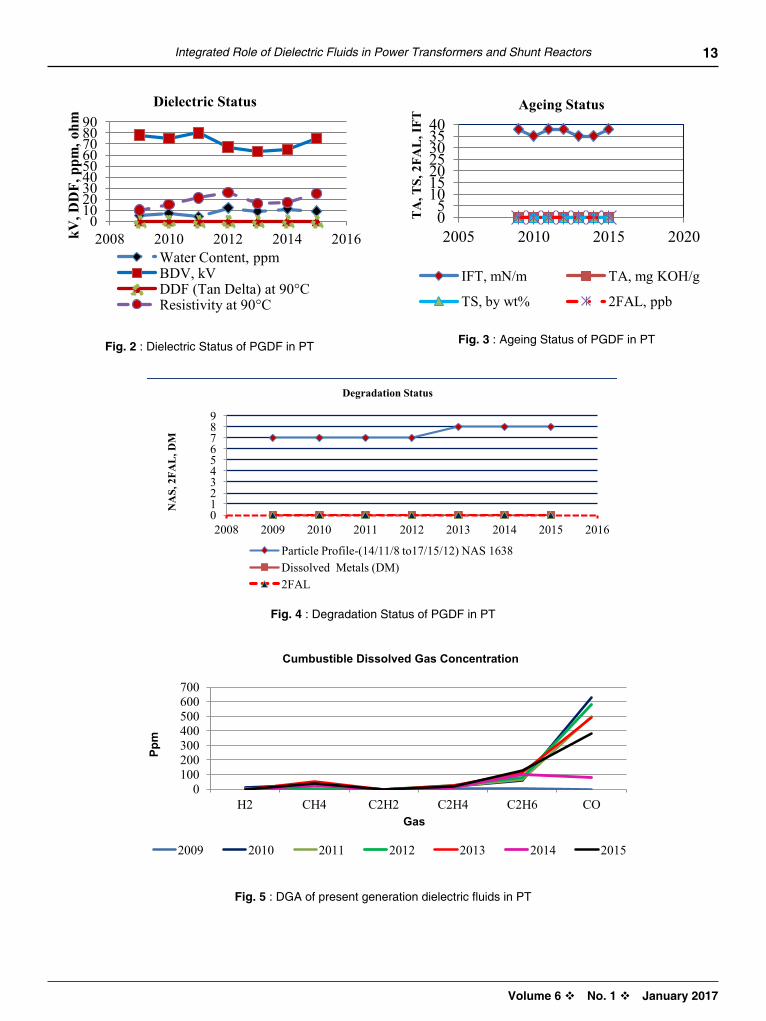
3. EXPERIMENTAL RESuLTS AND DISCuSSIONSPresentGenerationmodern catalytic hydroprocesseddielectric fluids (PGHDF) are in use inmany powertransformers and reactors in Indian utilities since thelast two decades. From the year 2009 onward wearemonitoring25powertransformersandreactors toevaluatetheirperformance
CASE STuDyOneoftheEHVtransformertakenupforourstudieswasmanufacturedin2003andcomissionedintheyear2004.Thehistoricaldataontheloadingconditions, typesof
repairsandinformationondielectricfluidisasshowninTable2.Thispowertransformerisbeingmonitoredfortheintegratedroleofpresentgenerationhydroprocesseddielectricfluidsince2009foritsdiagnosticinformation–characterizationoffluidparameters,dielectricstatus,ageingstatus,degradationstatusandkeycombustiblegas concentration as shown inFigures 2 - 5.All thedielectricproperties[7],[8]areregularyanalysedasperIEC60422andDGAasper IEEE-C57.104.ThedielectricpropertiesofthefluidarewellwithintherecommendedlimitsprescribedinIEC60422.InFigures4&5thetotalacidity-TA,totalsludge-TS&dissolvedmetals-DMvaluesarezeroandarenotreadable.
Table 2 :MonitoringDataonEHVTransformer
LoadingConditions,Repiars&DielectricFluidBasedInformation-315MVA,400kV/220kVEHVTransformer
QuantityofMCHDF,Ltr 84000
Agein-Service 11Years
DetailsofRepairs OLTCOilchangedin2012
YearofMonitoring 2009 2010 2011 2012 2013 2014 2015
PeakLoad,MW 180 160 140 150 180 180 300
OffPeakLoad,MW 90 85 74 55 110 55 50
PeakTemperature,°C 56 55 55 54 56 60 70
WindingTemperature,°C 50 50 56 56 58 52 57
Dielectric Status
WaterContent,ppm 5 7 4 12 9 11 9
BDV,kV 78 75 80 67 63 65 75
DDF(TanDelta)at90°C 0.002 0.0107 0.0063 0.0064 0.0134 0.0056 0.0065
Resistivityat90°C 10 15 21 26 16 17 25
Ageing Status
IFT,mN/m 38 35 38 38 35 35 38
TA,mgKOH/g 0.001 0.001 0.001 0.001 0.001 0.001 0.001
TS,bywt% 0.001 0.001 0.001 0.001 0.001 0.001 0.001
2FAL,ppb 0 0 0 0 0 0 0
Degradation Status
ParticleProfile-(14/11/8to17/15/12)NAS1638
7 7 7 7 8 8 8
DissolvedMetals(DM) 0 0 0 0 0 0 0
2FAL,ppb 0 0 0 0 0 0 0
13
Volume 6 v No. 1 v January 2017
Integrated Role of Dielectric Fluids in Power Transformers and Shunt Reactors
Figure 2 – Dielectric Status of PGDF in PT Figure 3 – Ageing Status of PGDF in PT
Figure 4 – Degradation Status of PGDF in PT
The dissolved combustible gas concentration is well within the limit as per IEEE guide for the interpretation as given in Table III. Where as the ethane gas is in conditon 2 limit apparently due to the contaminaion from the OLTC oil. The result is as shown in Figure 6.
Table III. Dissolved Gas Analysis of EHV Transformer
Gas, ppm Hydrogen Oxygen Methane Ethane Ethylene Acetylene Carbon Monoxide
Carbon Dioxide Nitrogen
2009 11 17900 2 1 1 0 0 270 38700
2010 9 2580 31 57 16 0 627 1969 61600
2011 0 4000 0 64 17 0 498 2154 32100
2012 4 25000 0 77 22 0 582 2216 50640
2013 0 5192 53 112 22 0 492 2350 56229
2014 0 22000 23 103 13 0 77 1709 59000
2015 0 3000 39 125 18 0 379 3029 70000
0 10 20 30 40 50 60 70 80 90
2008 2010 2012 2014 2016 Water Content, ppm BDV, kV DDF (Tan Delta) at 90°C Resistivity at 90°C
dielectric status kv
, dd
f, p
pm, o
hm
0 5
10 15 20 25 30 35 40
2005 2010 2015 2020
IFT, mN/m TA, mg KOH/g
TS, by wt% 2FAL, ppb
ageing status
ta
, ts,
2fa
l, I
ft
0 1 2 3 4 5 6 7 8 9
2008 2009 2010 2011 2012 2013 2014 2015 2016
Particle Profile-(14/11/8 to17/15/12) NAS 1638 Dissolved Metals (DM) 2FAL
degradation status
na
s, 2
fal
, dm
Figure 2 – Dielectric Status of PGDF in PT Figure 3 – Ageing Status of PGDF in PT
Figure 4 – Degradation Status of PGDF in PT
The dissolved combustible gas concentration is well within the limit as per IEEE guide for the interpretation as given in Table III. Where as the ethane gas is in conditon 2 limit apparently due to the contaminaion from the OLTC oil. The result is as shown in Figure 6.
Table III. Dissolved Gas Analysis of EHV Transformer
Gas, ppm Hydrogen Oxygen Methane Ethane Ethylene Acetylene Carbon Monoxide
Carbon Dioxide Nitrogen
2009 11 17900 2 1 1 0 0 270 38700
2010 9 2580 31 57 16 0 627 1969 61600
2011 0 4000 0 64 17 0 498 2154 32100
2012 4 25000 0 77 22 0 582 2216 50640
2013 0 5192 53 112 22 0 492 2350 56229
2014 0 22000 23 103 13 0 77 1709 59000
2015 0 3000 39 125 18 0 379 3029 70000
0 10 20 30 40 50 60 70 80 90
2008 2010 2012 2014 2016 Water Content, ppm BDV, kV DDF (Tan Delta) at 90°C Resistivity at 90°C
dielectric status
kv, d
df,
ppm
, ohm
0 5
10 15 20 25 30 35 40
2005 2010 2015 2020
IFT, mN/m TA, mg KOH/g
TS, by wt% 2FAL, ppb
ageing status
ta
, ts,
2fa
l, I
ft
0 1 2 3 4 5 6 7 8 9
2008 2009 2010 2011 2012 2013 2014 2015 2016
Particle Profile-(14/11/8 to17/15/12) NAS 1638 Dissolved Metals (DM) 2FAL
degradation status
na
s, 2
fal
, dm
Fig. 2:DielectricStatusofPGDFinPT Fig. 3:AgeingStatusofPGDFinPT
Fig. 4:DegradationStatusofPGDFinPT
Figure 2 – Dielectric Status of PGDF in PT Figure 3 – Ageing Status of PGDF in PT
Figure 4 – Degradation Status of PGDF in PT
The dissolved combustible gas concentration is well within the limit as per IEEE guide for the interpretation as given in Table III. Where as the ethane gas is in conditon 2 limit apparently due to the contaminaion from the OLTC oil. The result is as shown in Figure 6.
Table III. Dissolved Gas Analysis of EHV Transformer
Gas, ppm Hydrogen Oxygen Methane Ethane Ethylene Acetylene Carbon Monoxide
Carbon Dioxide Nitrogen
2009 11 17900 2 1 1 0 0 270 38700
2010 9 2580 31 57 16 0 627 1969 61600
2011 0 4000 0 64 17 0 498 2154 32100
2012 4 25000 0 77 22 0 582 2216 50640
2013 0 5192 53 112 22 0 492 2350 56229
2014 0 22000 23 103 13 0 77 1709 59000
2015 0 3000 39 125 18 0 379 3029 70000
0 10 20 30 40 50 60 70 80 90
2008 2010 2012 2014 2016 Water Content, ppm BDV, kV DDF (Tan Delta) at 90°C Resistivity at 90°C
dielectric status kv
, dd
f, p
pm, o
hm
0 5
10 15 20 25 30 35 40
2005 2010 2015 2020
IFT, mN/m TA, mg KOH/g
TS, by wt% 2FAL, ppb
ageing status
ta
, ts,
2fa
l, I
ft
0 1 2 3 4 5 6 7 8 9
2008 2009 2010 2011 2012 2013 2014 2015 2016
Particle Profile-(14/11/8 to17/15/12) NAS 1638 Dissolved Metals (DM) 2FAL
degradation status
na
s, 2
fal
, dm
Figure 5 – DGA of present generation dielectric fluids in PT
4. ConClusIon
As it will be observed the present generation hydro processed dielectric fluids perform excellently in its integrated role in the power transformer and reactors. The present generation dielectric fluids offer several advantages
Free from harmful corrosive sulfur, other contaminants and have better stability Excellent response to oxidation inhibitors – very slow depletion of inhibitor Excellent heat transfer capability at all temperature gradients including cold start Exceptional good stability ensure longer life for the asset Nontoxic, biodegradable and hence environmentally safe Better asset reliability, less breakdown risks Easily available at affordable costs Reduced maintenance requirements
5. aCknowlEdGEmEnts
The authors would like to thank their colleagues from technical service and QC departments for the technical support
6. bIblIoGRaPhy
[1] John E. Skog P.E. “Business Case for Transformer On-Line Monitoring” EPRI Diagnostic Conference – July 2006
[2] CIGRE Working Group12.18 “Life Management of Transformers” Draft Final Report Rev-2, 22 June 2002
[3] Victor Sokolov, A. Bassetto, T. V. Oommen, T. Haupert, and D. Hanson, “Transformer Fluid: A Powerful Tool for the Life Management of an Ageing Transformer Population” TechCon 2003 Asia-Pacific
[4] CIGRE Report of WG 12.18 “Moisture equilibrium & moisture migration within transformer insulation system”
[5] CIGRE Report of WG 12.17 “Effect of Particle on Transformer Dielectric Strength”
0 100 200 300 400 500 600 700
H2 CH4 C2H2 C2H4 C2H6 CO
2009 2010 2011 2012 2013 2014 2015
Ppm
Gas
Cumbustible Dissolved Gas Concentration
Fig. 5 :DGAofpresentgenerationdielectricfluidsinPT

14 CIGRE India Journal
Volume 6 v No. 1 v January 2017
4. CONCLuSIONAs it will be observed the present generation hydroprocessed dielectric fluids perform excellently in itsintegratedroleinthepowertransformerandreactors.
The present generation dielectric fluids offer severaladvantages
• Freefromharmfulcorrosivesulfur,othercontaminantsandhavebetterstability
• Excellentresponsetooxidationinhibitors–veryslowdepletionofinhibitor
• Excellentheattransfercapabilityatalltemperaturegradientsincludingcoldstart
• Exceptionalgoodstabilityensurelongerlifefortheasset
• Nontoxic,biodegradableandhenceenvironmentallysafe
• Betterassetreliability,lessbreakdownrisks
• Easilyavailableataffordablecosts
• Reducedmaintenancerequirements
AcknowledgementsTheauthorswould like to thank theircolleagues fromtechnicalserviceandQCdepartmentsforthetechnicalsupport
BIBLIOGRAPhy
1. JohnE.SkogP.E.“BusinessCaseforTransformerOn-LineMonitoring”EPRIDiagnosticConference–July2006
2. CIGREWorkingGroup12.18“LifeManagementofTransformers”Draft FinalReportRev-2, 22 June2002
3. Victor Sokolov, A. Bassetto, T. V.Oommen, T.Haupert, andD.Hanson, “Transformer Fluid: APowerfulToolfortheLifeManagementofanAgeingTransformer Population” TechCon 2003 Asia-Pacific
4. CIGREReportofWG12.18“Moistureequilibrium&moisturemigrationwithin transformer insulationsystem”
5. CIGREReportofWG12.17 “EffectofParticleonTransformerDielectricStrength”
6. K.Baburao,NalinNanavati,P.N.Narayanan“CriticalRoleofDielectricFluid in the lifeManagementofPowerTransformersandShuntReactors –CaseStudies”13thIndiaDoblePowerForum,Vadodara15-16October,2015
7. IEC 60422 - ed.4 “Mineral insulating oils inelectricalequipment-Supervisionandmaintenanceguidance”
8. InsulatingFluid–WGC-57.104-InsulatingFluids-DGAGuide
The dissolved combustible gas concentration iswellwithinthelimitasperIEEEguidefortheinterpretation
as given in Table 3.Where as the ethane gas is inconditon2limitapparentlyduetothecontaminaionfromtheOLTCoil.
Table 3:DissolvedGasAnalysisofEHVTransformer
Gas, ppm
hydrogen Oxygen Methane Ethane Ethylene Acetylene Carbon Monoxide
Carbon Dioxide
Nitrogen
2009 11 17900 2 1 1 0 0 270 387002010 9 2580 31 57 16 0 627 1969 616002011 0 4000 0 64 17 0 498 2154 321002012 4 25000 0 77 22 0 582 2216 506402013 0 5192 53 112 22 0 492 2350 562292014 0 22000 23 103 13 0 77 1709 590002015 0 3000 39 125 18 0 379 3029 70000

Volume 6 v No. 1 v January 2017
oPERatIonal ExPERIEnCE In 1200 kv natIonal tEst statIon (uhvaC), IndIa
I.S. Jha, B.N. De. Bhowmick, S.B.R. Rao, Dhyeya. R. Shah and Rachit SrivastavaPower Grid Corporation of India Limited
R.K. SinghBharat Heavy Electrical Limited, Bhopal
S.V. Kulkarni and Santosh KumarIndian Institute of Technology, Bombay
ABSTRACT
POWERGRID in association with Indian manufacturers have established a 1200kV National Test Station (NTS) at Bina, Madhya Pradesh, India with an objective of developing indigenous Ultra High Voltage AC (UHVAC) equipment and to gain first hand operational experience before full scale commercialization of UHVAC technology in Indian grid. The other objectives of this test station are to facilitate long term performance evaluation and carrying out optimization studies on 1200kV class equipment. Operational experience gained from NTS is very crucial for finalizing specifications of 1200kV equipment for the upcoming 1200 kV projects in India.
This paper gives a glimpse on present status of 1200 kV NTS facility and challenges faced during manufacturing, installation, commissioning and operation of the facility. This paper also describes a typical fault experienced in 1200 kV National Test Station (NTS) and its systematic investigation. Immediately, after charging of 1200 kV test station from 400 kV side of 400/1200 kV transformer (three single phase units) a flashover was seen on outer side of tank of one of these transformers and all three single phase units got tripped on over-current. It was initially assumed that there was fault internal to transformer however all test results showed that transformer was in healthy condition. In-depth study was carried out in PSCAD software, to simulate the actual scenario. The results of the simulation study are also discussed in this paper.
Keywords : 1200 kV, National test station, UHVAC, SFRA, Inrush current, Corona, Thermo vision scanning, Transformer, Circuit breaker, Fault
15
BACKGROuND1200kVNationalTestStation,Binahasbeenestablishedwith an objective of indigenous development ofUHVACequipment in Indiaand to facilitate long termperformanceevaluation&optimizationof1200kVclassequipment.1200kVNTSprojecthasbeendevelopedunderPublic-Private-Partnershipmodel(PPP),where-in equipment has been developed bymanufacturesindigenouslyandPOWERGRIDhasprovidedtestbedforperformanceevaluation&optimizationstudies.35Indianmanufacturershave joined theendeavourwithPOWERGRIDtoestablishthisproject.
1. 1200 kV NATIONAL TEST STATION - SALIENT DESIGN CONSIDERATIONS
Considering requirement of high power transfercapability, large size of equipment, transportationlimitations and cost optimization, the Indian 1200kV
systemhasbeendesignedwithanoptimuminsulationlevel(LIWL&SIWL)(Fig.1(a))andreducedprotectionmarginbyutilizinghighperformancemulti-columnsurgearrestors(Fig.1(b)).Continuousremotemonitoringisputin place tomonitor performanceof severely stressedsurgearrestors.Itwasenvisagedduringdesignstagethattapchangingshallbecarriedoutatlowervoltagelevellike400kVandaccordinglytapchangershavenotbeenprovidedwithauto-transformers.Though1200kVteststationisAirInsulatedSwitchgear(AIS)type,1200kVCircuitBreakerschosenaredeadtanktype(Fig.1(c))insteadoflivetankbecauseofstabilityconsiderations.Buspost insulatorsareof tripodarrangement.Towerstructuresat the teststationhavebeenprovidedwithprovision tovarygroundclearanceaswellasphase-phase clearance for experimentation.Engineering oftheswitchyardwascarriedoutfurthertoexperimentalstudiesfinalizingtheclearance(Fig.1(d))andconductor

16 CIGRE India Journal
Volume 6 v No. 1 v January 2017
andbusbarconfiguration.Conductorsusedinswitchyardandtestlinearehaving8sub-conductorsforCoronaandAudiblenoisecontrol.Technicalparametersof1200kV
equipmentwereobtainedbycarryingoutvariousstudiesandwere not extrapolated from existing 400/800kVsystem.
2. 1200 kV PROJECT OVERVIEw AND SINGLE LINE DIAGRAM
1200kVNationalteststationprojectisbeingimplementedintwophases(Phase-I&Phase-II).SingleLineDiagram(SLD)of1200kVNTSindicatingPhase-I&IIof1200kVNTS,BinaisgiveninFig.2.Phase-Iof1200kVprojectcomprisesofone1200kVbays&1.1kmofsinglecircuit
Fig. 1(a):Insulationlevelrequirementfordifferentvoltagelevels
(S/C) test line (Fig. 3(a))whilePhase-II comprisesofother1200kVbay&0.8kmdoublecircuit(D/C)testline(Fig.3(b)).Phase-Iof1200kVNTSincludingS/Ctestlinewaschargedunderno-loadconditionon26thMay,2012.Erectionworksinphase-IIarealreadycompletedand interconnectionworkson400kVsideofphase-IIareinprogress.CommissioningofPhase-IIwillestablishpowerflowthrough1200kVline.
Figure 1(b):1200kVMulti-columnsurgearrestors
Fig. 1(c):1200kVDeadtankbreaker Fig. 1(d):1200kVtowerwindowsimulation
1
BACKGROUND
1200kV National Test Station, Bina has been established with an objective of indigenous development of UHVAC equipment in India and to facilitate long term performance evaluation & optimization of 1200 kV class equipment. 1200kV NTS project has been developed under Public-Private-Partnership model (PPP), where-in equipment has been developed by manufactures indigenously and POWERGRID has provided test bed for performance evaluation & optimization studies. 35 Indian manufacturers have joined the endeavour with POWERGRID to establish this project.
1. 1200kV National Test Station - Salient Design Considerations
Considering requirement of high power transfer capability, large size of equipment, transportation limitations and cost optimization, the Indian 1200kV system has been designed with an optimum insulation level (LIWL & SIWL) (Fig.1(a))and reduced protection margin by utilizing high performance multi-column surge arrestors (Fig.1(b)). Continuous remote monitoring is put in place to monitor performance of severely stressed surge arrestors. It was envisaged during design stage that tap changing shall be carried out at lower voltage level like 400kV and accordingly tap changers have not been provided with auto-transformers. Though 1200kV test station is Air Insulated Switchgear (AIS) type, 1200kV Circuit Breakers chosen are dead tank type (Fig.1 (c)) instead of live tank because of stability considerations. Bus post insulators are of tripod arrangement. Tower structures at the test station have been provided with provision to vary ground clearance as well as phase-phase clearance for experimentation. Engineering of the switchyard was carried out further to experimental studies finalizing the clearance (Fig.1 (d)) and conductor and bus bar configuration. Conductors used in switchyard and test line are having 8 sub-conductors for Corona and Audible noise control. Technical parameters of 1200kV equipment were obtained by carrying out various studies and were not extrapolated from existing 400/800kV system.
Figure 1(a):Insulation level requirement for different voltage levels
Figure 1(b): 1200kV Multi-column surge arrestors
Figure 1(c): 1200kV Dead tank breaker
Figure 1(d): 1200kV tower window simulation
2
2. 1200kV Project Overview and Single Line Diagram
1200kV National test station project is being implemented in two phases (Phase-I & Phase-II). Single Line Diagram (SLD) of 1200kV NTS indicating Phase-I & II of 1200kV NTS, Bina is given in Fig.2. Phase-I of 1200kV project comprises of one 1200kV bays & 1.1 km of single circuit (S/C) test line (Fig. 3(a)) while Phase-II comprises of other 1200kV bay & 0.8 km double circuit (D/C) test line (Fig.3(b)). Phase-I of 1200kV NTS including S/C test line was charged under no-load condition on 26th May, 2012. Erection works in phase-II are already completed and interconnection works on 400kV side of phase-II are in progress. Commissioning of Phase-II will establish power flow through 1200kV line.
Figure 2: Single Line Diagram (SLD) of 1200kV National Test Station (NTS), Bina
Figure 3(a): 1200kV Single circuit test line (S/C tower height: 55m)
Figure 3(b): 1200kV Double circuit test line (D/C tower height: 125m)
Phase-I
Phase-II
Fig. 2 :SingleLineDiagram(SLD)of1200kVNationalTestStation(NTS),Bina

17
Volume 6 v No. 1 v January 2017
Operational Experience in 1200 kV National Test Station (UHVAC), India
3. PERFORMANCE EVALuATION OF EquIPMENT AFTER 1ST ChARGING
Onemajor objective of this project is to carry outperformanceevaluationandtocarryoutoptimizationstudiesonequipment.AllPre-commissioning&on-siteacceptancetestswerecarriedoutonequipmentof different makes and design, before chargingequipmentinNTS.Additionally,variousroutinetestsandmeasurementslikeElectricfield,Magneticfield,Thermo-vision scanning, Corona imaging, SFRA,In-rushcurrentmeasurements,voltageprofiling,etc.are being carried out to evaluate performance ofequipment and feedback is sharedwith respectivemanufacturers. Brief details/results of some of thekeymeasurements carried out after the successfulchargingeventarepresentedbelow:
(a)Recorded Voltage and Current Waveforms:1200kVvoltageandcurrentwaveformsrecordedunderno-loadconditionareshowninFig.5andtheirtypicalvaluesaretabulatedbelow:
Table 1:1200kVVoltageandCurrentunderno-loadconditions
Sl. No.
Parameter R-N y-N B-N
1. 1200kVsidevoltage
700kV 722kV 715kV
2. 1200kVsidecurrent
22.2A 18.8A 17.6A
2
2. 1200kV Project Overview and Single Line Diagram
1200kV National test station project is being implemented in two phases (Phase-I & Phase-II). Single Line Diagram (SLD) of 1200kV NTS indicating Phase-I & II of 1200kV NTS, Bina is given in Fig.2. Phase-I of 1200kV project comprises of one 1200kV bays & 1.1 km of single circuit (S/C) test line (Fig. 3(a)) while Phase-II comprises of other 1200kV bay & 0.8 km double circuit (D/C) test line (Fig.3(b)). Phase-I of 1200kV NTS including S/C test line was charged under no-load condition on 26th May, 2012. Erection works in phase-II are already completed and interconnection works on 400kV side of phase-II are in progress. Commissioning of Phase-II will establish power flow through 1200kV line.
Figure 2: Single Line Diagram (SLD) of 1200kV National Test Station (NTS), Bina
Figure 3(a): 1200kV Single circuit test line (S/C tower height: 55m)
Figure 3(b): 1200kV Double circuit test line (D/C tower height: 125m)
Phase-I
Phase-II
Fig. 3(a):1200kVSinglecircuittestline(S/Ctowerheight:55m)
Fig. 3(b):1200kVDoublecircuittestline(D/Ctowerheight:125m)
Fig. 4 :Sectionallayoutof1200kVbay
3
Figure 4: Sectional layout of 1200kV bay
3. Performance Evaluation of Equipment after 1st Charging
One major objective of this project is to carry out performance evaluation and to carryout optimization studies on equipment. All Pre-commissioning & on-site acceptance tests were carried out on equipment of different makes and design, before charging equipment in NTS. Additionally, various routine tests and measurements like Electric field, Magnetic field, Thermo-vision scanning, Corona imaging, SFRA, In-rush current measurements, voltage profiling, etc. are being carried out to evaluateperformance of equipment and feedback is shared with respective manufacturers. Brief details/results of some of the key measurements carried out after the successful charging event are presented below:
Recorded Voltage and Current waveforms: 1200kV voltage and current waveforms recorded under no-load condition are shown in Fig.5 and their typical values are tabulated below:
Sr. no. Parameter R-N Y-N B-N 1. 1200kV side voltage 700 kV 722kV 715 kV 2. 1200kV side current 22.2A 18.8A 17.6A
Table 1: 1200kV Voltage and Current under no-load conditions
Figure 5: Recorded 1200kV phase voltage and current waveforms

18 CIGRE India Journal
Volume 6 v No. 1 v January 2017
Table 2:Inrushcurrentsdrawnduringacharging
R-phase (rms) y-phase (rms) B-phase (rms)1.16kA 1.16kA 2.71kA
(b)Inrush Current:Inrushcurrentsarerecordedtokeepa check on transformer core condition.A typicalinrush current recorded from 400kV side duringchargingofNTSphase-Iaretabulatedbelow.Fig.6showsinrushcurrentwaveformsrecordedduringatypicalchargingevent.
3
Figure 4: Sectional layout of 1200kV bay
3. Performance Evaluation of Equipment after 1st Charging
One major objective of this project is to carry out performance evaluation and to carryout optimization studies on equipment. All Pre-commissioning & on-site acceptance tests were carried out on equipment of different makes and design, before charging equipment in NTS. Additionally, various routine tests and measurements like Electric field, Magnetic field, Thermo-vision scanning, Corona imaging, SFRA, In-rush current measurements, voltage profiling, etc. are being carried out to evaluateperformance of equipment and feedback is shared with respective manufacturers. Brief details/results of some of the key measurements carried out after the successful charging event are presented below:
Recorded Voltage and Current waveforms: 1200kV voltage and current waveforms recorded under no-load condition are shown in Fig.5 and their typical values are tabulated below:
Sr. no. Parameter R-N Y-N B-N 1. 1200kV side voltage 700 kV 722kV 715 kV 2. 1200kV side current 22.2A 18.8A 17.6A
Table 1: 1200kV Voltage and Current under no-load conditions
Figure 5: Recorded 1200kV phase voltage and current waveforms
4
Inrush current : Inrush currents are recorded to keep a check on transformer core condition. A typical inrush current recorded from 400kV side during charging of NTS phase-I are tabulated below. Fig.6 shows inrush current waveforms recorded during a typical charging event.
R-phase (rms) Y-phase (rms) B-phase (rms) 1.16 kA 1.16 kA 2.71 kA
Table 2: Inrush currents drawn during a charging
Figure 6: Recorded inrush current waveforms during a typical charging event.
Corona measurements: Corona performances of all equipment after charging were assessed for their effectiveness in limiting corona. Fig. 7 shows the corona performance of 1200kV corona ring installed on transformer bushing. Issue of high corona was faced with some of the line connectors due to surface distortion and same were re-installed after repair/smoothening of surfaces as a part of corrective action.
Figure 7: Corona image taken by handheld corona camera near 1200kV bushing
Thermo-vision scanning: Thermo-vision scanning of equipment was carried out under no-load condition to detect any abnormalities in the operating temperature or hot spots in the equipment. No abnormalities were observed during the test except in one of the line connectors and it was attributed to loose connection, which was resolved. Fig.8 below shows thermo-vision scanning images taken for transformer, bushing of 1200kV CB and 1200kV surge arrestor. Once power flow is established after works in phase-II and interconnection activities are completed from
Fig. 5:Recorded1200kVphasevoltageandcurrentwaveforms
Fig. 6:Recordedinrushcurrentwaveformsduringatypicalchargingevent
(c)Corona Measurements:Coronaperformancesofallequipment after chargingwereassessed for theireffectiveness in limiting corona.Fig. 7 shows thecoronaperformanceof1200kVcoronaringinstalledontransformerbushing.Issueofhighcoronawasfacedwithsomeofthelineconnectorsduetosurfacedistortionandsamewere re-installedafter repair/smoothening of surfaces as a part of correctiveaction.
(d)Thermo-vision Scanning:Thermo-visionscanningofequipmentwascarriedoutunderno-loadconditiontodetectanyabnormalitiesintheoperatingtemperatureorhotspotsintheequipment.
Fig. 7:Coronaimagetakenbyhandheldcoronacameranear1200kVbushing

19
Volume 6 v No. 1 v January 2017
Operational Experience in 1200 kV National Test Station (UHVAC), India
Noabnormalitieswereobservedduringthetestexceptinoneofthelineconnectorsanditwasattributedtolooseconnection,whichwasresolved.Fig.8showsthermo-visionscanningimagestakenfortransformer,bushingof1200kVCBand1200kVsurgearrestor.
(e)Assessment of Electrostatic Induction:Theelectricfieldstrengthwasmeasuredaroundtheperipheryofthemajorequipmentin1200kVbayat1m&1.8mabove the ground level and 1m away from theequipment and measured values were foundgenerallyinorder(<4kV/m).
4. FAuLT EXPERIENCED IN 1200KV NTS FACILITy AND ITS INVESTIGATION
Progressivelyequipmentweredeveloped,installedandcharged inNTS facility. The1200kV test stationwasre-charged after the installation of following 1200kVequipment:
Oncepowerflowisestablishedafterworksinphase-II and interconnectionactivities are completed from400kVside,thermo-visionscanningoftheequipmentwill be carried out again which will be helpful invalidatingtheirthermaldesign.
Fig. 8(a):Thermographimageofbushingturretoftransformer
Fig. 8(b):Thermographimageofthetransformerbody
Fig. 8(c):Thermographimageof1200kVCB Fig. 8(d):Thermographimageof850kVsurgearrestor
5
400kV side, thermo-vision scanning of the equipment will be carried out again which will be helpful in validating their thermal design.
Figure 8(a): Thermograph image of bushing turret of transformer
Figure 8(b): Thermograph image of the transformer body
Figure 8(c): Thermograph image of 1200kV CB Figure 8(d): Thermograph image of 850kV surge arrestor
Assessment of electrostatic induction: The electric field strength was measured around the periphery of the major equipment in 1200kV bay at 1 m&1.8m above the ground level and 1m away from the equipment and measured values were found generally in order (< 4kV/m).
4. Fault Experienced in 1200kV NTS Facility and its Investigation:
Progressively equipment were developed, installed and charged in NTS facility. The 1200kV test station was re-charged after the installation of following 1200kV equipment:
a) Circuit Breakers in R & Y-phase b) One three phase isolator c) Single phase isolator installed in R-phase
After charging from 400kV side, R-phase of NTS phase-I was tripped by instantaneous over-current protection and a flashover was observed outside the tank (Fig. 10) between transformer tank cover and main tank body. General technical parameters of 400/1200kV transformer are given in Table 3.
(a)CircuitBreakersinR&Y-phase
(b)Onethreephaseisolator
(c)SinglephaseisolatorinstalledinR-phase
Afterchargingfrom400kVside,R-phaseofNTSphase-Iwas tripped by instantaneous over-current protectionandaflashoverwasobservedoutsidethetank(Fig.10)between transformer tank coverandmain tankbody.Generaltechnicalparametersof400/1200kVtransformeraregiveninTable3.

20 CIGRE India Journal
Volume 6 v No. 1 v January 2017
Table 3:Generaltechnicalparametersof400/1200kVTransformer
Parameter Specification
RatedPower 333/333/111MVA,singlephase
VoltageRatio 1150/√3/400/√3/33kV
Ratedfrequency 50Hz
Connection Ynaod11
%Imedance HV-IV18%HV-LV40%IV-LV20%
WindingLIWV 2250/1300/325kVp
WindingSIWV 1800/1050/325kVp
BushingLIWV 2550/1425/325/95kVp
BushingSIWV 1950/1050/325/5kVp
Colingtype ODAForOFAF
Coolingequipment 4*33%UnitOFAFcoolers
TempRise 45degC:Wdg40degC:TopOil
Fig. 9:Schematicdiagramof1200kVNationalTestStationindicatinglocationoffault
Asflashoverwasseenonoutersideoftransformertankinordertoensurethehealthinessoftransformer,seriesoftestswerecarriedoutontransformerandsamearelistedbelow:
• DGA,BDV,PPM,Tanδetc.oftransformeroilandbushingoil
• Capacitance&Tanδmeasurementfromwindingstotankandbetweenwindings
• Capacitance&Tanδmeasurementofbushings
• Insulation resistance measurement of CC toFrame
• Insulation ResistanceMeasurement of bushingCTs
• ContinuitytestonbushingCT(IV/HV)
• WindingresistanceofIVBushingCT
• Magnetizingcurrenttest
• Transformerwindingresistancemeasurement
• Earthpitresistancemeasurement
• SFRAmeasurementsofTransformer
All the test resultswere found to be in linewith pre-commissioning test results exceptSFRA results andmagnetizingcurrent.Magnetizingcurrentoftransformerincreasedslightlybutitwasnotsignificant.SFRAresultswereshowingaminorshift in lowfrequencyrangeasshowninFig.11.Shortingstripsconnectingtankcoverandmaintankbodywerefoundtobe intact;howeverasasafetymeasureshortingstripswerereplacedaftercleaningofcontactsurface.
6
Figure 9: Schematic diagram of 1200kV National Test Station indicating location of fault
Parameter Specification Rated Power : 333/333/111MVA,
single phase Voltage Ratio : 1150/3 / 400/3
/33kV Rated frequency : 50Hz Connection : Ynaod11 % Im edance :
: :
HV-IV 18% HV-LV 40% IV-LV 20%
Winding LIWV : 2250/1300/325kVp Winding SIWV : 1800/1050/325kVp Bushing LIWV : 2550/1425/325/95kVp Bushing SIWV : 1950/1050/325/ 5kV
p C oling type : ODAF or OFAF Cooling equipment
: 4*33% Unit OFAF coolers
Temp Rise : 45degC:Wdg 40degC:Top Oil
Figure 10: Snapshot of the flashover seen on the R-phase transformer
Table 3: General technical parameters of 400/1200kV Transformer
As flashover was seen on outer side of transformer tank in order to ensure the healthiness of transformer, series of tests were carried out on transformer and same are listed below:
• DGA, BDV, PPM, Tan etc. of transformer oil and bushing oil • Capacitance & Tan measurement from windings to tank and between windings • Capacitance & Tan measurement of bushings • Insulation resistance measurement of CC to Frame • Insulation Resistance Measurement of bushing CTs • Continuity test on bushing CT (IV/HV)
400kV bus
1200kV side1200/400kV Transformer bank
400kV lines
Presently charged 1200kV Circuit Breaker
400kV Circuit Breaker
Fig. 10 :SnapshotoftheflashoverseenontheRphasetransformer

21
Volume 6 v No. 1 v January 2017
Operational Experience in 1200 kV National Test Station (UHVAC), India
Fig. 11:SFRAof1200kVtransformerwindingshowingshiftinLowfrequencyrange&snapshotofCIGRE
TB:342showingeffectofmagnetizedcoreonSFRAresults
7
• Winding resistance of IV Bushing CT • Magnetizing current test • Transformer winding resistance measurement • Earth pit resistance measurement
• SFRA measurements of Transformer
All the test results were found to be in line with pre-commissioning test results except SFRA results and magnetizing current. Magnetizing current of transformer increased slightly but it was not significant. SFRA results were showing a minor shift in low frequency range as shown in Fig. 11. Shorting strips connecting tank cover and main tank body were found to be intact; however as a safety measure shorting strips were replaced after cleaning of contact surface.
Figure 11: SFRA of 1200kV transformer winding showing shift in Low frequency range & snapshot of CIGRE TB:342showing effect of magnetized core on SFRA results
Following were considered as the probable causes of flashover seen on outer side of transformer tank before detailed investigation:
• Loosening of shorting strips between tank cover and main tank • Change in earth resistance between the earth pit and neutral earthing terminal • Improper earthing of transformer tank, cooler bank and firefighting pedestals • Saturation of transformer core due to over voltage • Presence of winding earth Fault • Failure of one of the bushing’s
• Failure of bushing CTs
5. Observations from Disturbance Recorder (DR) Waveforms
Disturbance recorder waveforms were studied in detail, to get an overall idea of fault scenario. Observations made from the disturbance recorder waveforms are as under: 1. Inrush current drawn by R-phase (IV_SIDE_IL123 (R, Y and B-phase) in Fig. 12) transformer for
first few cycles was of the same order as drawn by Y-phase, B-phase and during previous charging events. Also it was observed that inrush current drawn by transformer were decaying in first few
8
cycles before fault occurred. Hence it was concluded that transformer core was not saturated prior to charging.
Figure 12: Disturbance recorder waveforms of 400 kV side bay CT currents
2. Before occurrence of fault, 400kV side R-phase voltage (HV_PT_UL1_3MS/kV in Fig.13) was quite stable and was within acceptable limits. There was no over-voltage situation which can saturate transformer core. Further, it was found (Fig.13) that during fault period, R-phase voltage and current were in phase and a DC component was present in R-phase current.
Figure 13: Recorded waveforms of 400 kV side voltage and currents.
Followingwereconsideredas theprobablecausesofflashoverseenonoutersideoftransformertankbeforedetailedinvestigation:
• Looseningofshortingstripsbetweentankcoverandmaintank
• Change inearth resistancebetween theearthpitandneutralearthingterminal
• Improperearthingoftransformertank,coolerbankandfirefightingpedestals
• Saturationoftransformercoreduetoovervoltage• PresenceofwindingearthFault• Failureofoneofthebushing’s• FailureofbushingCTs
5. OBSERVATIONS FROM DISTuRBANCE RECORDER (DR) wAVEFORMS
Disturbancerecorderwaveformswerestudiedindetail,to get anoverall ideaof fault scenario.Observationsmadefromthedisturbancerecorderwaveformsareasunder:1. InrushcurrentdrawnbyR-phase(IV_SIDE_IL123(R,
YandB-phase)inFig.12)transformerforfirstfewcycleswasofthesameorderasdrawnbyY-phase,B-phaseandduringpreviouschargingevents.Alsoitwasobservedthatinrushcurrentdrawnbytransformerweredecayinginfirstfewcyclesbeforefaultoccurred.Henceitwasconcludedthattransformercorewasnotsaturatedpriortocharging.
2. Before occurrence of fault, 400kV sideR-phasevoltage(HV_PT_UL1_3MS/kVinFig.13)wasquitestable andwaswithin acceptable limits. Therewasnoover-voltage situationwhich can saturatetransformercore.Further,itwasfound(Fig.13)thatduring fault period,R-phase voltage and currentwereinphaseandaDCcomponentwaspresentinR-phasecurrent.
Fig.12:Disturbancerecorderwaveformsof400kVsidebayCTcurrents

22 CIGRE India Journal
Volume 6 v No. 1 v January 2017
zero and hencewinding to earth fault was notpresent.
3. CurrentsrecordedbyREFprotection(REF_IL123forR,YandB-phaseinFig.14)relayswerealmost
9
3. Currents recorded by REF protection (REF_IL123 for R, Y and B-phase in Fig.14) relays were almost zero and hence winding to earth fault was not present.
Figure 14: Recorded waveforms of REF protection of transformer, stand-by earth Fault relay and neutral current measured on 400kV side
4. R-phase standby earth fault CT current (STANDBY_EF_IN/kA Fig.14) was found to be less than that of 400kV side neutral current which indicated a possibility of line to earth Fault on 1200kV side (outside the R-phase transformer) and hence there was a presence of DC bias in R-phase current.
6. Simulation Results and Analysis
Based on the observation made from the disturbance recorder waveforms above, it was decided to carry out detailed simulation study for single phase line to ground fault on 1200kV side. In order to simulate the L-G fault a model of 1200kV NTS was prepared in PSCAD software (Fig. 15) and same was simulated. 1200kV circuit breakers were provided in R and Y-phase in the simulation model, as it was in actual condition.
CVT has been modelled with an equivalent capacitance value since parameters such as burden, compensation inductances, and losses were not available. Charging of the NTS is governed by 400 kV circuit breakers and same has been used in the simulation model and their operation was defined in thetime logic.
Neutral current measured on 400kV side
8
cycles before fault occurred. Hence it was concluded that transformer core was not saturated prior to charging.
Figure 12: Disturbance recorder waveforms of 400 kV side bay CT currents
2. Before occurrence of fault, 400kV side R-phase voltage (HV_PT_UL1_3MS/kV in Fig.13) was quite stable and was within acceptable limits. There was no over-voltage situation which can saturate transformer core. Further, it was found (Fig.13) that during fault period, R-phase voltage and current were in phase and a DC component was present in R-phase current.
Figure 13: Recorded waveforms of 400 kV side voltage and currents. Fig. 13:Recordedwaveformsof400kVsidevoltageandcurrents
Fig. 14:RecordedwaveformsofREFprotectionoftransformer,stand-byearthFaultrelayandneutralcurrentmeasuredon400kVside
4. R-phasestandbyearthfaultCTcurrent(STANDBY_EF_IN/kAFig.14)was found to be less than thatof 400kV side neutral currentwhich indicated apossibility of line to earth Fault on 1200kV side(outsidetheR-phasetransformer)andhencetherewasapresenceofDCbiasinR-phasecurrent.
6. SIMuLATION RESuLTS AND ANALySISBasedon theobservationmade from thedisturbancerecorderwaveformsabove,itwasdecidedtocarryoutdetailedsimulationstudyforsinglephaselinetogroundfault on 1200kV side. In order to simulate the L-Gfaultamodelof1200kVNTSwaspreparedinPSCAD

23
Volume 6 v No. 1 v January 2017
Operational Experience in 1200 kV National Test Station (UHVAC), India
software (Fig. 15) and samewas simulated. 1200kVcircuitbreakerswereprovidedinRandY-phaseinthesimulationmodel,asitwasinactualcondition.
CVThasbeenmodelledwithanequivalentcapacitancevaluesinceparameterssuchasburden,compensation
inductances,and losseswerenotavailable.ChargingoftheNTSisgovernedby400kVcircuitbreakersandsamehasbeenusedinthesimulationmodelandtheiroperationwasdefinedinthetimelogic.
10
Figure 15: 1200kV NTS Circuit model to simulate and analyze the Fault condition
A condition similar to the single phase line-to-ground fault was created in the model using the circuit breaker BRK6 in Fig. 15, the instant of the fault was chosen to approximately to match with the actualmeasurement. The switching sequence of the breakers was chosen similar to the actual charging sequence at the site.
Fig. 16: 400kV side R-phase current measured and simulated waveform
It can be seen from Fig.16 that when line is charged under normal condition, charging currents are drawn by all three single-phase transformers. However, when single phase line-to-earth fault is created
Acondition similar to the single phase line-to-groundfaultwascreatedinthemodelusingthecircuitbreakerBRK6inFig.15,theinstantofthefaultwaschosento
Fig. 15 :1200kVNTSCircuitmodeltosimulateandanalyzetheFaultcondition
approximately tomatchwith theactualmeasurement.The switching sequenceof thebreakerswas chosensimilartotheactualchargingsequenceatthesite.
Fig. 16:400kVsideR-phasecurrentmeasuredandsimulatedwaveform
10
Figure 15: 1200kV NTS Circuit model to simulate and analyze the Fault condition
A condition similar to the single phase line-to-ground fault was created in the model using the circuit breaker BRK6 in Fig. 15, the instant of the fault was chosen to approximately to match with the actualmeasurement. The switching sequence of the breakers was chosen similar to the actual charging sequence at the site.
Fig. 16: 400kV side R-phase current measured and simulated waveform
It can be seen from Fig.16 that when line is charged under normal condition, charging currents are drawn by all three single-phase transformers. However, when single phase line-to-earth fault is created

24 CIGRE India Journal
Volume 6 v No. 1 v January 2017
It canbeseen fromFig.16 thatwhen line is chargedunder normal condition, charging currents are drawnbyallthreesingle-phasetransformers.However,when
400kVsideR-phasevoltageasseeninFig.18reducesduringthefaultconditionandissimilartothatobservedintheactualrecordedwaveformsatthesite(thepeakpre-
Fig. 18:400kV(MV-Mediumvoltage)sideR-phasevoltageundermeasuredandsimulation
11
in the R-phase, high fault current flows in R-phase, and while other two phases still carry charging currents of the transformers (Fig. 17).
Figure 17: 400kV side current Y and B-phase currents – Simulation
400kV side R-phase voltage as seen in Fig. 18 reduces during the fault condition and is similar to that observed in the actual recorded waveforms at the site (the peak pre-fault voltage = (400/ ) = 326.6 kV). This significant voltage drop is due to very high fault current flowing through the line.
Figure 18: 400kV (MV-Medium voltage) side R-phase voltage under measured and simulation
The R-phase 1200kV side voltage reduces significantly because of the fault condition as shown in Fig.19, which is similar to that recorded during the measurements.
Figure 19: 1200kV side voltage comparison – measured and simulation
The agreement of simulation results with the actual recorded waveforms indicated a strong possibility of a single line to earth fault in the R-phase and its presence was confirmed during further investigation of R-phase circuit breaker. Hence it was concluded that single line to earth fault occurred
TheR-phase1200kVsidevoltagereducessignificantlybecauseofthefaultconditionasshowninFig.19,which
singlephaseline-to-earthfaultiscreatedintheR-phase,highfaultcurrentflowsinR-phase,andwhileothertwophasesstillcarrychargingcurrentsofthetransformers(Fig.17).
Fig. 17 :400kVsidecurrentYandB-phasecurrents–Simulation
faultvoltage=(400/√3)√2=326.6kV).Thissignificantvoltagedrop is due to very high fault current flowingthroughtheline.
issimilartothatrecordedduringthemeasurements.
Fig. 19:1200kVsidevoltagecomparison–measuredandsimulation

25
Volume 6 v No. 1 v January 2017
Operational Experience in 1200 kV National Test Station (UHVAC), India
savE onE unIt a daykEEP PowER Cut away
The agreement of simulation resultswith the actualrecordedwaveformsindicatedastrongpossibilityofasinglelinetoearthfaultintheR-phaseanditspresencewasconfirmedduring further investigationofR-phasecircuitbreaker.Henceitwasconcludedthatsinglelinetoearthfaultoccurredafter50-60msofchargingthelineanditwasapermanentlinetoearthfault.Later,1200kVNationalTestStation(NTS)wassuccessfullychargedafterby-passingR-phasecircuitbreakerinthecircuit.
Phenomenon of flashover between the tank coverandmaintankof transformerwasduetoasignificantvoltagedifferencebetweenthetwopartsduetohighercontact resistanceof theshorting linksbetween them(forexampledue topaint).Thebottomtankpartmayget raised to a highpotential valuedue to the singlephaseline-to-earthfaultcurrentflowingthroughtheearthcircuit,whichcan raise thebottom tankpotential toafew thousandsofvolts (taking theearth resistanceof0.5ohms,thevoltagelevelcanbeapproximately0.5×peakvalueofthefaultcurrent=0.5×12kA=6kV).Thisvoltagemaybeenoughtocauseamomentaryflashoverbetweenthetwotankpartsexternally.
Minor shift in the SFRA of transformer indicates apossibilityoflocalsaturationoftransformercorewhichnormallyoccurswhen transformer feeds faultcurrent.Localsaturationofcoremaycausetheleakagefluxtolinkwithtankandwouldresult intoinducedvoltageintankcover.Iftheinducedvoltageissufficientlyhighandiftotalcurrentdischargingcapabilityofshortinglinksisnot sufficient then thisvoltagemaygetdischarged toearthedtankviaair(flashover).Thispossibilitywillbefurtherstudiedindetail.
7. CONCLuSIONThe establishment of 1200kVNational Test Station,Binahashelpedindevelopmentandindigenizationof
UHVAC equipment in India. The experience gainedfrom establishment and operation of 1200kV NTSfacilityisverycrucialforPOWERGRIDindesigningandfinalizingtechnicalspecificationofUHVACequipment.POWERGRIDhasuseditsexperienceindesigningofWardha-Aurangabad transmission line in India,whichhasbeendesignedfor1200kVvoltagelevelconsideringfuture power requirements, though the line will bechargedinitiallyat400kVvoltagelevelandsubsequentlywill be upgraded to 1200kV after completion of fieldstudiesat1200kVNTS.
Theestablishmentandoperationof1200kVNTSfacilityhasalsohelpedmanufacturerstovalidatedesignoftheirequipmentandevenoptimizethem,bywayofreceivingcontinuous feedback fromPOWERGRID regardingperformance of equipment in test facility. Itwill alsohelpthemtobebecomegloballeadersindevelopmentofUHVACproducts.ExperiencegainedfromthisfaultincidentinNTSfacilityhasgivenabetterinsighttothetransformer&circuitbreakermanufacturersregardingtheirdesignaspectsandsamewillbetakencareoffinfuturedesignsoftheirequipment.
BIBLIOGRAPhy1. L.YaoB. Li, E. Zaimi,K.Uehara,Y.Shirasaka,
B. N. De. Bhowmick “The situation of UHVACtransmissionsystem& its standarization”CIGRE/IEC International symposiumonDevelopment ofelectricityinfrastructureinSub-SaharanAfrica,SouthAfrica2015
2. Dr.S.K.Agrawal,D.P.Tamoli,B.N.De.Bhowmick,B.N.V.R.C.Sureshkumar,S.B.Rao&AkhilSundaran“1200kVNationalTestStation:TakingIndianpowersystemtonextorbit”,CIGREInternationalcolloquiumonUltraHighVoltage,NewDelhi2013

Volume 6 v No. 1 v January 2017
EnsuRInG hIGh QualIty InsulatIon systEm of laRGE motoRs – dEsIGn & tEstInG
REQuIREmEnts
A.K. Gupta, D.K. Chaturvedi and P.K. BasuNTPC Limited
ABSTRACT
In recent past, several high voltage motor winding failures occurred within one year of commissioning in two of NTPC projects. They include bearing failures, winding cable connection failure at termination and winding insulation failures in overhang region. During review it was found that some of the important requirements, which ensures healthy machine insulation system have not been taken care during manufacturing process. The commonly observed deficiencies in manufacturing process of end winding are:
• Poorly done brazing at bus connection.
• Poor workmanship causing uneven air clearances.
• Selection of inadequate cable and lug size, leading to heating and subsequent failure.
• Pre-VPI activities done in uncontrolled (non-air conditioned) environment.
This paper discuss the type of failure occurred, analyses the root cause and mitigation measures. It gives insight to best practices being adopted in machine manufacturing and testing to ensure high quality of insulation system.
The importance of minimum clearance between two adjacent coils has been discussed in the paper. The paper also suggests the minimum clearances to be maintain between insulation surface of two adjacent coils of same phase and different phases. It emphasize on use of software based advance coil taping and coil spreader machines instead of old conventional practices to ensure shape of coil as per design. The use of automated coil spreading and automatic taping machine avoids presence of wrinkles, knots and lashes, maintain adequate clearances in overhang, a very important aspect to ensure quality of capsule. The paper describes the effect of taping method on machine life. It discusses the advantages of machine taping over manual taping.
It also covers other critical design requirement in high voltage motor overhang insulation. It suggests criteria for selection of winding cable connection, termination arrangement and best practice for coil brazed joints. Some of very important tests namely Corona Imaging Test, Monitoring of cable lug temperature at termination using RTD, partial discharge test have been suggested to be conducted as `ROUTINE TESTS’. The use of infrared camera as routine test to check healthiness of winding lead termination has been suggested.
CAuSES OF FAILuREOverhangpart ofwindingexperienceshigh thermalandmechanicalstress.Ithasbeenseenduringtestingof largewater cooledmachine, the temperature ofRTD in slot portion is almost 10-12 deg. C lowerthanthetemperatureexistsinoverhangportion.Themechanicalforcesarealsohigherinendwinding.The
currentchangesdirectionatthecoilendportion,whichispoorlysupportedascomparedtoslotportion.
Asregardstoelectricalstress,theslotportionofcoilisprovidedwithsemiconductivecoatingwhichkeepstheinsulationsurfaceatzeropotential.Asthecoilcomesoutoftheslotportion,somelengthisprovidedwithtransitiontape for coronaprotection.The transition tapeavoids
26

27
Volume 6 v No. 1 v January 2017
Ensuring High Quality Insulation System of Large Motors – Design & Testing Requirements
3
Fig.1: PRESENCE OF KNOTS, LASHES AND LOWER AIR GAP BETWEEN PHASES Some of these failures are bearing failure caused by solidification of grease due to long storage of machine and several other failures were attributed to poorly done insulation during manufacturing (see Figure-2).
Fig.2 LOW CLEARANCE BETWEEN ADJACENT PHASE BUS CONNECTION
Fig. 1:PresenceofKnots,LashesandLowerAirGapbetweenPhases
Someof these failuresarebearing failure causedbysolidificationofgreaseduetolongstorageofmachineandseveralotherfailureswereattributedtopoorlydoneinsulationduringmanufacturing(Figure2).
thesurfacetrackingonthecoilasthepotentialbeyondthiszoneinoverhangportionisveryhighwithrespecttoground.Thispotentialatinsulationsurfaceduringhighvoltageisalmost80%oftheappliedvoltage.Whereas,during running ofmachine the potential in overhangportionofcoilvaries,andcanbeupto85%ofratedph-phvoltageatthecoilconnectiontophaseterminals.
Thereforewecansaythatthemachinecoilissubjectedtoveryhighthermal,mechanicalandelectricalstressesintheoverhangportionofwinding.
Ithasbeenseenthatseveral large6.6kVand11kVmachinesarebeingmanufacturedwithmanuallytappedinsulation,where knots, lashes and uneven air gapsbetweenadjacentphasescanbeseenatseveralplaces(Figure1).Thesemachinescanrunforfewyears,buthavehighwindinginsulationfailurerate.Ithasbeenseenthatinaspanoftwoyears,morethan20HighVoltagemotorsfailedattwoofNTPCprojects.
Fig. 2:LowClearancebetweenAdjacentPhaseBusConnection
Theairgapbetweentheadjacentphasecoilsandphasebus connectionwas observed varying from 1.0mmto14.0mm in11kVmotors.Theuneven tapingandpresenceofwrinklesininsulationcanbeseenalmosteverywhere(Figure3).
Suchmachineshavehighpartialdischargeactivityandpronetofailureon`LinetoGround’faults(Fig.4).
4
The air gap between the adjacent phase coils and phase bus connection was observed varying from 1.0 mm to 14.0 mm in 11kV motors. The uneven taping and presence of wrinkles in insulation can be seen almost everywhere (see figure 3).
Fig.3 WRINKLE CAN BE SEEN IN OVERHANG CONNECTIONS Such machines have high partial discharge activity and prone to failure on `Line to Ground’ faults (Fig. 4).
Fig.4. LINE TO GROUND FAILURE IN OVERHANG Several high voltage machine manufacturers, finds dimensional control in motor winding overhang very difficult.
Fig. 3 :WrinklecanbeSeeninOverhangConnections Fig. 4:LinetoGroundFailureinOverhang

28 CIGRE India Journal
Volume 6 v No. 1 v January 2017
CoilSpreaderMachine
RemedyThedimensionalcontrol canbeachievedbyuseofcoilspreadermachine.Thismachinecangivethecoils
Fig. 6 :PoorlyDoneCableTerminationArrangement
Several high voltagemachinemanufacturers, findsdimensional control inmotorwinding overhang verydifficult.
desiredshapewithhighdimensionalandgeometricalaccuracyasperpre-loadedsoftware.CoilSpreadersaredesignedtoformcoilsfromloopspriortopressing.Theyaretypicallyusedtoformdiamondcoilsofhighquality.
Low Clearance at Bus Connection OverlapIthasbeenseeninsomelarge11kVmotorsthatbrazingwasdoneatbusconnectionwithtwoflatsoverlappingandthereforeofferingverylowclearancebetweenbus-connection of twodifferent phases (Figure 2). Thesegapsareunevenduetopoorworkmanship.
RemedyEspeciallydesignedT-connectorscanbeusedtoensureadequateclearancesatsuchlocations.
Failure at Cable TerminationTheselectionofcableandinadequatelugsizecausedheatingandsubsequentfailureatconnectionofwindingleadtotheterminationarrangement.(Fig.6)
5
Coil Spreader Machine Remedy:
The dimensional control can be achieved by use of coil spreader machine. This machine can give the coils desired shape with high dimensional and geometrical accuracy as per pre-loaded software. Coil Spreaders are designed to form coils from loops prior to pressing. They are typically used to form diamond coils of high quality.
low Clearance at bus Connection overlap
It has been seen in some large 11kV motors that brazing was done at bus connection with two flats overlapping and therefore offering very low clearance between bus-connection of two different phases (Figure-2). These gaps are uneven due to poor workman ship. Remedy:
Especially designed T-connectors can be used to ensure adequate clearances at such locations.
Infewcasesitisfoundthatcross-sectionoflugatitsneckisverylowascomparedtothewindingphaseconductorcrosssection.Thisaddsuphighresistanceandheatingnearthecabletermination.
RemedyThesectionofcablehastobecompatibletothecrosssection of the conductor.As the forces duringmotorstatingisveryhighbetweentwoadjacentphases
6
failure at Cable termination
The selection of cable and inadequate lug size caused heating and subsequent failure at connection of winding lead to the termination arrangement. (See fig. 6)
Fig.6. POORLY DONE CABLE TERMINATION ARRANGEMENT In few cases it is found that cross-section of lug at its neck is very low as compared to the winding phase conductor cross section. This adds up high resistance and heating near the cable termination.

29
Volume 6 v No. 1 v January 2017
Ensuring High Quality Insulation System of Large Motors – Design & Testing Requirements
FaI2 and Fa1/d,
Where ‘I’ is thestartingcurrentand ‘d’ is thespacingbetweentwoadjacentconductors.Thecableconnectionto the terminationhas tobeproperlydressedupandsupportedtotakecareofhighforcesduringstartingofthemotor.
Measurement of lead connection temperature atterminal shouldbemademandatorybyplacingRTD/thermocouple. Use of infrared camera to checkhealthinessofwindingleadterminationduringheatruntestcanalsobeconsideredasroutinetest.
Avoiding wrinkles and Lashes in TappingThewrinklesandlashesasseeninFig.1andFig.3canbeavoidedbyuseofautomatictappingmachine.Ithasbeenexperimentedthatinsulationdielectricstrengthinautomatictappingisveryhighascomparedtothemanualtapping.Thetimetoinsulationbreakdownofacoilfoundtobeaverage50-100timestothatofmanuallytappedcoil,whenpowerfrequencyhighvoltageisappliedforlongduration.
SuGGESTED STEPS DuRING VPI CAPSuLE MANu-FACTuRING TO ENSuRE hIGh quALITy IN wINDING OVERhANG:1. Thecoilmanufacturingofhighvoltagemotorshave
tobedoneincontrolledenvironmentpreferablyairconditionedtoavoidanycontaminationdepositonthe coils duringmanufacturing.Themoistureandtemperaturecontrolisalsoveryimportanttohavegoodqualitywinding.
2. Storage of insulationmaterial shall be at lowtemperature (e.g. 5 deg. C to 15 deg.) as permanufacturer’s recommendation. The coi lmanufacturing,assemblyandVPIprocessshallbecompletedwithin30daysofbeingtakenoutofcoldstorage.
3. Theinsulationtapingonbar/coilhastobedoneusingsoftwarecontrolledinsulationtapingmachine,soastoensurelongevityandhighresistancetoelectricalstress.
4. Thecoilshouldbeformedsoastojustfitintheslottoavoidanycoronadischargeduringitslifespan.Theshapeconsistencyhastobeensuredbyuseof special coil spreadermachinehaving softwarecontrolledoperation.Theshapeofeachcoilhastobeensuredasperthedesignrequirement.
5. Priortowindingassemblyshapeofcoilhastobechecked.Itshouldfitintheslotwithoutputtinganyimpactontheinsulation.
6. ThewindingconnectionsaretobebrazedandshouldusestandardT-connectors,whereveroverlappingresultsinlowclearance.
7. TheVPI process shall be done as per standardprocedureandshallbeconsideredcompleteasandwhenthe tandeltavalueofwindingduringcuringprocessreachestospecifiedvalue.
SuGGESTED TESTS TO ENSuRE OVERALL wIND-ING quALITyThe overall quality of high voltagemotor capsule isensuredbyconductingfollowingtests:
(a)Tan delta and tip us test – at factory aswell astrendingeveryyearatinstallation.
(b)Corona Imaging test at 115% rated voltage afterassembly.
(c)PartialDischargeMeasurementafterassemblyaswellastrendingeveryyear.
TAN DELTA TIP uP TESTThetandeltaandcapacitancetipuptestisoneofthebestteststoestablishthehealthinessofwindingoverallinsulation system. Thewinding is stressed to ratedvoltage level and capacitance ismeasured at 20%and80%of ratedvoltage(refer IEEE286). Ideally thewindingcapacitanceshouldnotchange.Theresultsofthemanufacturingstagearekeptasreferenceandusedwhileconductingthetestatsiteaftermachinecompletedfew(3-5)yearsofoperation.Subsequentlyeveryyearthetesthastobeconducted.Thetrendingoftipupshouldnotshowadeviationofmorethan1percentperyear.Theconductionofothertwotestsmentionedabovecanfurtheraugmenttheresult.
CORONA IMAGING TESTThe corona imaging test is done at 115% of ratedvoltage.ThistestvoltageisappliedtothewindingandcoronadischargesarecapturedusingUVcamera.TheUVcameraresultscanbecomparedwiththeblackouttest,wherethePDactivityisseenbynakedeyewhenwinding is applied115%of rated voltage.The test isconducted for 15minutes, to give adequate time forvisualcheck.Novisualdischargesshallbeseeninthewindingduringthetest.TheIEEE1799-2012elaboratesthetestmethod.
Different remedialmeasures havebeendiscussed inIEEE1799 standard to ensure corona free overhangwinding. The corona free endwinding ensures highqualityofinsulationandlongevityoftheequipment.
OFFLINE PARTIAL DISChARGE TESTThemeasurementofofflinepartialdischargesateverymachine overhaul and trendingwith earlier resultsindicates the overall condition ofmachine insulationsystem.AnyincreasingtrendofPDindicatesdeteriorationofinsulationsystemquality.

30 CIGRE India Journal
Volume 6 v No. 1 v January 2017
CLEARANCES BETwEEN ADJACENT PhASESInadequateair clearancesbetween insulation surfaceofadjacentphaseconductorresultsinpartialdischargeactivity in overhangwindingand if continues for longduration can damage the winding insulation. Theinsulationsurfaceofcoilisprovidedwithsemiconductivecoatingtomaintainzeropotentialoninsulationsurface,whenmachineisappliedratedortesthighvoltage.Thisensuresnopartialdischargeinslotportion.
As thecoilcomesoutofslot, transition tapecoveringadequate length is provided to avoid tracking oninsulationsurface.Theelectricalstress(kV/mm)seenbyairgapisalmost4-5timestothatacrosswindingmaininsulation resultingunevenvoltagedistributionacrossinsulationandairgap.Thevoltageonoverhangwindinginsulationsurfaceisclosetothephasevoltageduringmachineoperation.
Table 1 :ClearancesbetweenPhasetoPhaseandPhasetoGroundinoverhangwinding
Sl. No.
Voltage grade in
kV
hV test voltage in
kV
Ph-Ph clearance in mm (nom./
min.)
1 6.6 14.2 5.0/3.0
2 11 23 8.0/7.0
3 13.8 28.6 10.0/8.0
VOLTAGE DISTRIBuTION BETwEEN ADJACENT PhASES
Thevoltagedistributionworkedoutasbelowestablishthatthecoilinsulation,whichhasaveryhighelectricalstrength(voltagebreakdownlevel)issubjectedtomuchlower electrical stress (kV/mm) as compared higherelectricalstressacrossairgap,whichhasalowervoltagebreakdownlevel.
Theinsulationthickness‘tk’ifconsideredas2mmandthegap‘d’as6mmfor11kVmotorwinding.Thecapacitancebetweentwoparallelplatesis
C=€A/t
Where‘€’isthepermittivityofmedium,‘A’istheareaofplateand‘t’isthespacingbetweentwoplates.
Thevoltageappearsacrossairgapduringhighvoltagetestwillbe inverselyproportional to thepermittivityofmedium.Thereforeelectricalstressacrossairmediumwillbe5timesthatofthemeasuredacrossinsulation.
Aspercalculation,thevoltageappliesacrossairin11kVmachinewillbe20.3kVand therefore thevoltagestressacrossairduringhighvoltagetestwillbe3.4kV/mm.Itwillbesafetoselecttheairgapbetweenadjacentphaseconductorsasnominal8.0mm(minimum7.0mm).Thosemachine,whichhaslowergapbetweenphasesarealsofoundinoperationbuttheinsulationagingrateisfast.ContinuousPDdeterioratestheinsulationwithtimeandcausefailure.
CONCLuSIONThe quality of high voltagemotor insulation systemcan to be ensured by adopting bestmanufacturingpractices.Use of software controlled coil taping, coilspreading and other equipments,which ensures theshapeconsistencyisnecessary.Thedesignphasetophaseandphasetogroundclearancearenecessarilyto be ensured in overhangwinding.Also the overallassessmentofmachinewindinginsulationsystemcanbedonebyconducting tandelta& tipup test,partialdischargemeasurementandcoronaimagingbestusingultravioletcamera.
10
d d tk figure-7 Electrical clearance between adjacent conductor in overhang The insulation thickness ‘tk’ if considered as 2mm and the gap ‘d’ as 6mm for 11kV motor winding. The capacitance between two parallel plates is
C= €A/t Where ‘€’ is the permittivity of medium, ‘A’ is the area of plate and ‘t’ is the spacing between two plates. The voltage appears across air gap during high voltage test will be inversely proportional to the permittivity of medium. Therefore electrical stress across air medium will be 5 times that of the measured across insulation. As per calculation, the voltage applies across air in 11kV machine will be 20.3kV and therefore the voltage stress across air during high voltage test will be 3.4kV/mm. It will be safe to select the air gap between adjacent phase conductors as nominal 8.0 mm (minimum 7.0 mm). Those machine, which has lower gap between phases are also found in operation but the insulation aging rate is fast. Continuous PD deteriorates the insulation with time and cause failure. ConClusIon The quality of high voltage motor insulation system can to be ensured by adopting best manufacturing practices. Use of software controlled coil taping, coil spreading and other equipments, which ensures the shape consistency is necessary. The design phase to phase and phase to ground clearance are necessarily to be ensured in overhang winding. Also the overall assessment of machine winding insulation system can be done by conducting tan delta & tip up test, partial discharge measurement and corona imaging best using ultra violet camera.
Fig. 7:Electricalclearancebetweenadjacentconductorinoverhang
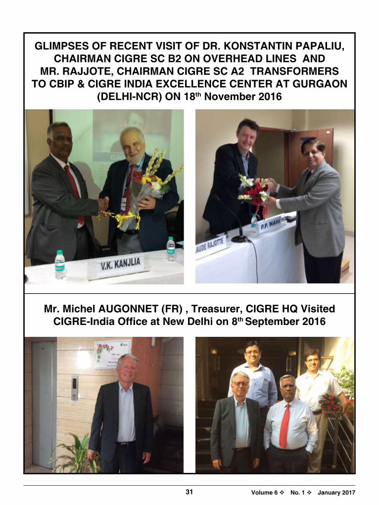
Volume 6 v No. 1 v January 2017
Mr. Michel AuGONNET (FR) , Treasurer, CIGRE hq Visited CIGRE-India Office at New Delhi on 8th September 2016
GLIMPSES OF RECENT VISIT OF DR. KONSTANTIN PAPALIu, ChAIRMAN CIGRE SC B2 ON OVERhEAD LINES AND
MR. RAJJOTE, ChAIRMAN CIGRE SC A2 TRANSFORMERS TO CBIP & CIGRE INDIA EXCELLENCE CENTER AT GuRGAON
(DELhI-NCR) ON 18th November 2016
31

Volume 6 v No. 1 v January 2017 32
CIGRE (Camseil International des Grands Réseaux Électriques - International Council on Large Electrical Systems)isoneoftheleadingworldwideOrganizationsonElectricPowerSystems,coveringthetechnical,economic,environmental,organizationalandregulatoryaspects.CIGRE-Paris aswell asCIGRE-India has 16 studygroups, each specializing in one specific technicaldomain.Indiahasamemberineachofthesegroups.
Accordingly, CIGRE-India had divided this two-dayconference into various sections/ parallel sessions.The respective CIGREGroupmember chaired thesession. The participantswere acquaintedwith thepapersselectedbyCIGREGroup,bywayofasummarypresentationofeachpaperandthequeriesthereto.Theparticipantswereaskedtopresenttheirviewsinrespectofthequeries,including,anyIndia-specificissues.
(L-R) Mr. V.K. Kanjlia, Secretary, CBIP on Podium, Mr. P.P. Wahi, Director, CBIP; Mr. Amitabh Mathur, Director (IS&P), BHEL & Vice President, CIGRE-India; Mr. R.P. Sasmal, Director (Operations), POWERGRID & Chairman –Technical, CIGRE-India; Mr. Atul Sobti, CMD, BHEL, Mr. Gurdeep Singh, CMD, NTPC; Mr. S.D. Dubey, Chairperson, CEA & President, CBIP; Mr. I.S. Jha, CMD, POWERGRID & President CIGRE-India; Mr. K.M. Singh, CMD, NHPC; Mr. K.K. Sharma, Director (Operations), NTPC & Vice President, CIGRE-India, and Mr. N.N. Misra, Former Director (Operations) NTPC & Vice Chairman-Technical, CIGRE- India; during inaugural session
CIGRE India Session 2016
natIonal ConfEREnCE onGlobal tREnds
and InnovatIons In dEvEloPmEnt of PowER
sECtoR28-29July2016,NewDelhi

Volume 6 v No. 1 v January 201733
Activity of the Society
CIGRE (INDIA) IS ThE NATIONAL COMMITTEE OF CIGRE PARISCIGRE-India hadorganizedaConferenceon “GlobalTrendsandInnovationsinDevelopmentofPowerSector”on28-29July2016atScopeConventionCenter,LodhiRoad,NewDelhi.ThisNationalConferencewasplannedpriortoCIGRE-ParisSession2016todiscussaboutthefollowingactivities.• To share experience and update knowledge on
Developments&InnovationsinPowerSystem.
• TohavetheinputandconsideredopinionfromtheexpertswithinthecountryonvarioustopicsaswellasontechnicalpapersbeingpresentedinCIGRESession2016atParis.
The unique event addressed by Chairperson, CEA;
CMD, POwERGRIDL; CMD, NTPC; CMD, BhEL and
CMD NhPC and attended by more than 300 professionals from
India and Bhutan

34 CIGRE India Journal
Volume 6 v No. 1 v January 2017
Mr. S.D. Dubey, Chairperson, CEA & President, CBIP, addressing the participants during inaugural session
Mr. I.S. Jha, CMD POWERGRID & President CIGRE-India, addressing the participants during inaugural session
• ToproposerepliesonvariousquestionsputupbyspecialreportersoftechnicalsessionofCIGREatPariswhichcouldberaisedanddiscussedwiththeInternationalexpertsduringthesession.
• ToplanoutstrategytobeadoptedbytheIndiandelegatesattendingtheCIGREParisSession2016toensuremaximumbenefitsfortheIndianEngineers.
Theconferencewaswidelyattendedby300participantsfromIndiaandBhutan.
PriortoTechnicalsession,therewasinauguralsessionon28thJuly2106inwhichfollowingdignitarieswerepresentondais.
• Mr.S.D.Dubey,Chairperson,CEA&President,CBIP
• Mr.I.S.Jha,CMDPOWERGRID&PresidentCIGRE-India
• Mr.GurdeepSingh,CMD,NTPC
• Mr.AtulSobti,CMD,BHEL
• Mr.K.M.Singh,CMDNHPC
• Mr.R.P.Sasmal,Director(Operations),POWERGRID&Chairman–Technical,CIGRE-India
• Mr.K.K.Sharma,Director(Operations),NTPC&VicePresident,CIGRE-India
• Mr.AmitabhMathur,Director(IS&P),BHEL&VicePresident,CIGRE-India
• Mr.N.N.Misra,FormerDirector(Operations),NTPC&ViceChairman-Technical,CIGRE-India
IntheinauguralsessionthewelcomeaddresswaspresentedbyMr.V.K.Kanjlia,Secretary,CBIPinwhichhebriefedregardingtheobjectiveofconference.Itwasalsointimatedbyhimthat18papershavebeenselectedfromIndiatobepresentedinCIGRE-Parissession.
WhileaddressingonthisoccasionMr.P.P.WahihighlightedthecontributionofMr.MataPrasadatNationalandInternationallevel.
Mr.I.S.Jha,CMD,POWERGRIDandPresidentCIGRE-Indiaaddressedtheparticipants.HeappreciatedCBIPandCIGRE-IndiaforprovidingsuchhugeplatformtotheEngineerstosharetheirexperiences.HealsoemphasizedthevariousproblemsbeingfacedbythePowersectorandcorrectiveactionstobetaken.

35
Volume 6 v No. 1 v January 2017
Activity of the Society
Mr.K.M.Singh,CMD,NHPCinhisaddresscongratulatedtheawardwinnersfor theirsignificantcontribution inPowersector.HealsocongratulatedtotheauthorswhosepapershavebeenselectedinCIGREParissession.HeemphasizedthatthepowersectorisintransitionstageandalotofchangeisgoingtotakeplaceinnextdecadeduetocomingupofrenewableenergysectorwhichwillbemajorsourceofEnergyinfuture.Thereisaneedforimprovementintheefficiency,reliabilityandqualitypower,needforreductioninthegenerationcost.HealsoemphasizedthatCIGRE-Indiaprovidestheopportunitytodiscussthevariousissuesatoneplatform.
Mr.GurdeepSingh,CMD,NTPCalsocongratulatedtheauthorswhosepapershavebeenselectedinCIGREParissession.Heexpressedhisconcernthatpowersectorisenteringindifferentscenarioeverydayandthereisaneedofenvironmentalfriendly,24x7reliablepowerataffordableprice.HealsohighlightedthattheaveragepoolpriceofPowerin1stquarterwasaroundRs3/-perunitandhencethereisneedtoreducethetarifftothecustomersbytheUtilities.
Mr.AtulSobti,CMD,BHELemphasizedthatthereisrapidgrowthinIndiabutstillintermsofpercapitaconsumptionwearelaggingmuchbehindtheotherCountries.Althoughwearesurplusinpowertodaybutwehavetothinkforthenext5years.Renewableenergyhastoplaykeyroleinthecountryandweexpectthat8%growthcanbemetbyRenewableEnergy.Still70%ofgenerationisfromThermalPowerandhencetomeetupthegrowthinthepowersectortheuseofcoalismostimportant.HesaidthattheroleofThermalgenerationthereforecannotbesetaside.ThereplacementofoldThermalunitswithsupercriticalunitsisthebetteralternative.Hebroughtoutthatpoliciesarestilluncertainandneedsreview.
Mr.S.D.Dubey,Chairperson,CEAandPresident,CBIPalsohighlightedtheimportanceofthisconferenceastherewillbelotofdeliberationsontheissuesrelatedtopowerforall,qualitypower,reliabilityandataffordableprice.HealsohighlightedtheachievementsofPowersectorinIndialike300+GWofGeneration,Constructionof1200kVlinesundertheleadershipofPOWERGRID,EstablishmentofhightestinglabatBinaetc.Healsoemphasizedthatwiththeinductionof175GWrenewablepowerupto2022,alotofchallengeslikeoperationalissuesinrespectofTransmissionandDistribution,storageproblemetc.arelikelytobefaced.Healsoemphasizedthatin12thfiveyearplan40%generationfromcoalwillbefromsupercriticalunitandalotofcontributionfromthemanufacturerswillberequired
Mr. Gurdeep Singh, CMD, NTPC, addressing the participants during inaugural session
Mr. Atul Sobti, CMD, BHEL, addressing the participants during inaugural session

36 CIGRE India Journal
Volume 6 v No. 1 v January 2017
In the lastof inauguralsession,voteof thankswaspresentedbyMr.P.P.Wahi,Director,CBIPandDirectorCIGRE-India.HethankedalltheCMD’sforsparingtheirvaluabletimetogracetheinauguralsession.Healsothankedtoalltheparticipantsandspecialinvitees.Itwasalsoinformedbyhimthat2no.postsinCIGRE-IndiahasrecentlybeencreatedandMr.R.P.Sasmal,Director(Operations),POWERGRIDisChairman-Technical,andMr.N.N.Misra,FormerDirector(Operations),NTPCasViceChairman-TechnicalofCIGRE-India.
TEChNICAL SESSIONS16TechnicalSessionswereconductedinparallelHallson28-29July2016asperfollowingschedule.
PROGRAMME
1030 - 1200
28.7.2016 29.7.2016
hall 1 hall 2 hall 1 hall 2
Transformers InformationSystems&Telecommunications
Substations SystemDevelopment&Economics
1200 -1330 OverheadLines ElectricityMarkets&Regulation
RotatingElectricalMachines
SystemOperation&Control
1430 -1600 HighVoltageEquipment Materials&EmergingTestTechniques
HVDC&PowerElectronics
InsulatedCables
1630 -1800 SystemTechnicalPerformance
Protection&Automation DistributionSystems&DispersedGeneration
SystemEnvironmentalPerformance
Mr. K.M. Singh, CMD NHPC, addressing the participants during inaugural session
Mr. V.K. Kanjlia, delivering the welcome address during inaugural session

37
Volume 6 v No. 1 v January 2017
Mr. M. Vijaya Kumaran
Activity of the Society
TEChNICAL SESSION ON SySTEM TEChNICAL PERFORMANCE (SC C4)ChairedbyMr.S.K.Negi,Chairman,NationalStudyCommitteeC4whichcoversthe technical progress in different fields suchaspower quality, electromagneticcompatibilityandinterference,insulationcoordination,lightningandpowersystemperformancemodelsandnumericalmethods.Therearetotal35papersinthestudygroupinPreferentialSubject1,2&3.
PS1–ImpactofInverterBasedGenerationandEnergyStorage(17Papers)PS2–ChallengeswithModelingandEvaluationofLightningPerformanceandIn-
sulationCoordinationinthePowerSystemofFuture(12Papers)PS3–BridgingtheGapBetweenEMT,FEMandPositiveSequenceGridSimula-
tion(6Papers)
TEChNICAL SESSION ON TRANSFORMERS (SC A2) ChairedbyMr.M.VijayaKumaran,Chairman,NationalStudyCommitteeA2,whichcoversall kindsof power transformersaswell as all activities related to design,manufactures,applicationofmaterials,safety /environmental issues,economic /commercialaspects,qualityassuranceandtesting.Therearetotal37papersinthestudygroupinPreferentialSubject1,2&3.
PS1–AdvancesinTransformerDiagnosticsandMonitoring(16Papers)PS2–EHV/UHVandEHVDC/UHVDCTransformersandtheirComponents,Shunt
Reactor(10Papers)PS3–TransformerWindings(11Papers)
TEChNICAL SESSION ON OVER hEAD LINES (SC B2) ChairedbyMr.Gopal Ji,Chairman,NationalStudyCommitteeB2which coversmechanicalandelectricaldesignandexperimentalvalidationofnewlinecomponents,performanceandassessmentofagedlinecomponents,constructionandoperationofoverheadlines,upratingofexistingoverheadlines.Therearetotal39papersinthestudygroupinPreferentialSubject1,2&3.
PS1–OverHeadLinesforHighPowerTransferCapacity(15Papers)
PS2–ProjectManagement,ConstructionandMaintenance(12Papers)
PS3–ApplicationofNewMaterialsandTechnologies(12Papers)
TEChNICAL SESSION ON hIGh VOLTAGE EquIPMENT (SC A3)ChairedbyMr.R.K.Tyagi,Chairman,NationalStudyCommitteeA3.Therearetotal29papersinthestudygroupinPreferentialSubject1,2&3.
PS1–HighVoltageEquipmentforEmergingSystemConditions(19Papers)PS2 – Life Time Management of Transmission and Distribution Equipment
(5Papers)PS3–ApplicationofInformationTechnologyToolsforDevelopmentand
ManagementofHighVoltageEquipment(5Papers)
Mr. S.K. Negi
Mr. Gopal Ji
Mr. R.K. Tyagi

38 CIGRE India Journal
Volume 6 v No. 1 v January 2017
TEChNICAL SESSION ON ELECTRICITy MARKETS & REGuLATIONS (SC C5)ChairedbyMr.S.K.Soonee,CEO,POSOCOandChairmanofSCC5.PaperspresentedbyMr.KaushikDey,SrEngineer,Mr.K.V.N.PawanKumar,Sr.Engineer,Mr.K.B.V.RamKumar,Engineer,Mr.ShubenduMukherjee,Dy.ManagerandMr.SubhashKumar,Engineer.Therearetotal30papersinthestudygroupinPreferentialSubject1,2&3.PS1–The Future of Regulation in the Evolving Market: Interactions between
WholesaleandRetailMarkets.(4papers).PS2–MarketModelsandRegulatoryStructuresinanEvolvingIndustrySituation
(18Papers)PS3–Distributed Resource, Demand Response and Storage Technology
Integration from the Perspective of Electricity Market and RegulatoryStructures(8Papers)
TEChNICAL SESSION ON MATERIALS & EMERGING TEST TEChNIquES (SC D1)ChairedbyMr.JithinSunder,ED,BHEL,ChairmanNSCD1.HewasSupportedbyDrM.MohanaRao,DGM,BHEL,Dr.SukumarRoy,Sr.DGM,BHELandMr.A.Pradeep,Dy.Manager,BHEL.Therearetotal32papersinthestudygroupinPreferentialSubject1,2&3.PS1–CompactInsulationSystems(ACandDC)(13papers)PS2–NewMaterials(8papers)PS3–Non-standardisedStressesandEmergingTestTechniques(11papers)
Mr. Jithin Sunder
Mr. S.K. Soonee
TEChNICAL SESSION ON INFORMATION SySTEMS & TELECOMMuNICATIONSChaired byMr. N.S. Sodha, former ED, PGCILandoutgoingChairmanofNSCD2alongwithMr.PrakashNayak,MD, Power Engg & AutomationwhoistheincomingChairmanofNSCD2.MrP.K.AgarwalofPOSOCO,supportedforpresentationofpapers.Therearetotal31papersinthestudygroupinPreferentialSubject1,2&3.TherearetwoIndianPapers(D2-302ofMrP.K.Agarwal&D2-303ofMr.N.S.Sodha).Therearetotal31papersinthestudygroupinPreferentialSubject1,2&3.PS1–Information andTelecommunication Technologies forConnectingDistributedEnergyResources (16 pa-
pers)PS2–MaintainingOperationalITReliabilityinanEvolvingEnvironment(5papers)PS3–TrendsinManagingUtilityCommunicationNetworks(10papers)Technical Session on Protection & Automation (SC B5)Chaired by outgoing Chairman Mr. S.G. PatkialongwithincomingChairmanMr.SubhashThakur,AGM,NTPCofNSCB5.AfterintroducingbyMr.S.G.Patki,summaryofthepapersdeliveredbyMr.SubhashThakur.Thereare total35papers in thestudygroupinPreferentialSubject1&2.PS1–ProtectionAutomationandControlSystem(PACS)OptimizationandLifeTimeAssetManagement(21Papers)PS2–Co-ordinationofGeneratorandPowerSystemProtection(14Papers)
Mr. S.G. Patki Mr. Subhash Thakur
Mr. Prakash NayakMr. N.S. Sodha

39
Volume 6 v No. 1 v January 2017
TEChNICAL SESSION ON ROTATING ELECTRICAL MAChINES (SC A1)ChairedbyMr.D.K.Chaturvedi,Chairman,NationalStudyCommitteeA1whichcoversresearch,designanddevelopment,manufacture,materialtechnology,operationandmaintenanceandassetmanagement.Therearetotal19papersinthestudygroupinPreferentialSubject1,2&3.
PS1–DevelopmentsofRotatingElectricalMachine(14Papers)
PS2–AssetManagementofElectricalMachines(4Papers)
PS3–RotatingMachineforRenewableandDispersedGeneration(1Paper)
TEChNICAL SESSION ON SuB-STATION (SC B3)ChairedbyMr.RajilSrivastava,Chairman,NationalStudyCommitteeB3whichcoversdesign,construction,maintenanceandongoingmanagementofsubstationandelectricalinstallationinpowerstationexcludinggenerator.Therearetotal38papersinthestudygroupinPreferentialSubject1,2&3.
PS1–AdvancesinSubstationTechnologies(14Papers)
PS2–DevelopmentsandNewThinkinginSubstationsDesign(13Papers)
PS3–EvolutioninSubstationManagement(11Papers)
TEChNICAL SESSION ON hVDC & POwER ELECTRONICS (SC B4)ChairedbyMr.OomenChandy,Chairman,NationalStudyCommitteeB4.Therearetotal45papersinthestudygroupinPreferentialSubject1,2&3.
PS1–HVDCSystemandtheirApplications(31Papers)PS2 –FACTSand otherPowerElectronicSystem for TransmissionSystem (9
Papers)PS3–DC,FACTSandotherPowerElectronicSystemforDistributionSystem(5
Papers)
TEChNICAL SESSION ON DISTRIBuTION SySTEM AND DISPERSED GENERATION (SC C6) ChairdedbyDr.SubirSen,Chairman,NationalStudyCommitteeC6.Therearetotal38papersinthestudygroupinPreferentialSubject1,2&3.
PS1–IntegratedPlanningandOperationforUpgradingDistributionNetwork(19Papers)
PS2–EnergyInfrastructureforUpgradingDistributionsNetworks(9Papers)PS3–MicrogridsandOffGridHybridSystem(10Papers)
Activity of the Society
Dr. Subir Sen
Mr. Rajil Srivastava
Mr. Oomen Chandy
Mr. D.K. Chaturvedi

40 CIGRE India Journal
Volume 6 v No. 1 v January 2017
TEChNICAL SESSION ON SySTEM OPERATION & CONTROL (SC C2)ChairedandpresentedpapersbyMr.K.V.S.Baba,ChairmanofNSCC2andED,NLDC,POSOCOsupportedbyMrAdityaPrasadDas,MrM.K.Ramesh,MrSaugatMandal,Mr.DebashishandMr.SunilKumar.Therearetotal38papersinthestudygroupinPreferentialSubject1&2.
PS1–GridOperationSolutionstoChangesinGenerationMixIncludingDistributedandRenewableGeneratingResources(25papers)
PS2–ManagingSystemDisturbancesandSystemRestoration(13papers)
TEChNICAL SESSION ON SySTEM DEVELOPMENT AND ECONOMICS (SC C1)ChairedandpresentedthepapersbyMs.SeemaGupta,ChairmanofNSCC1andED,POWERGRIDsupportedbyMr.AshokPal,GM,POWERGRID.Therearetotal36papersinthestudygroupinPreferentialSubject1,2&3.
PS1– StateoftheArtApproachesandStandardizationinAssetManagementDecisionMaking(6Papers)
PS2– InterfaceandAllocationIssuesinPlanningT&DNetworkswithMulti-PartyProj-ects(7Papers)
PS3– NewSystemSolutionsandPlanningTechniquesforFlexibleandRobustSystemPlans(23Papers)
TEChNICAL SESSION ON INSuLATED CABLES (SC B1)ChairedandpresentedpapersbyMr.DeepalShah,ChairmanofNSCB1.Therearetotal39papersinthestudygroupinPreferentialSubject1,2&3.
PS1– NewlyInstalledorUpgradedCableSystems(9Papers)PS2– BestUseofExistingCableSystems(16papers)PS3– FutureInsulatedCablesinPowerSystem(14papers)
TEChNICAL SESSION ON SySTEM ENVIRONMENTAL PERFORMANCE (SC C3)ChairedandpresentedpapersbyMr.AnishAnand,ChairmanofNSCC3andGeneralManager,POWERGRID,India.Therearetotal17papersinthestudygroupinPreferentialSubject1,2&3.
PS1–EnvironmentalLiabilitiesofTransmission&DistributionAssets(4papers)
PS2–OverheadLinesandUndergroundCables:AcceptabilityIssues(8Papers)
PS3–ClimateChange:ImplicationsforElectricPowerSystems(5papers)
ACDcontainingthecopyofpresentationswasdistributedtotheparticipants.
VOTE OF ThANKSMr.P.PWahiandMr.S.K.LambapresentedvoteofthanksinHall-1andHall-2respectively.Theythankedallthespeakers&delegates.Theyalsoappreciatedfortheirpresentationsandparticipationintheconference.Mr.WahigavegoodwishestotheauthorswhosepapershavebeenselectedforpresentationinCIGREParissession2016.
POSTER SESSIONThepostersessionwasalsoorganizedfortheauthorstopresenttheirpaperswhichhavebeenselectedforCIGREParissession.
Ms. Seema Gupta
Mr. Deepal Shah
Mr. Anish Anand
Mr P.P. Wahi, Director, CBIP proposing vote of thanks
Mr. K.V.S. Baba

41
Volume 6 v No. 1 v January 2017
Activity of the Society
A view of the participants during inaugural sessionPoster Session
Mr. S.G. Patki receiving Distinguish Members AwardMr. S.K. Soonee receiving Distinguish Members Award
Mr. S.K. Negi receiving Distinguish Members AwardMr. Mata Prasad, Founder President of CIGRE-India was honoured with Life Time Achievement Awards
AwARDS AND RECOGNITIONDistinguishMembersAwardwas introduced inCIGRE toacknowledge thesignificantcontributionof itsmembers,overanumberof years to theworkanddevelopmentofCIGRE.Following threeexpertswereselected fordistinguishedmembershipawardbyCIGREHQ,Parisfortheyear2016:Mr.S.K.Negi,M.D.,GETCOforSystemTechnicalPerformance,Mr.S.K.Soonee,CEO,POSOCOforMarketandRegulations,Mr.S.G.PatkifromTataPowerforProtectionandAutomationTheaboveexpertswerehonouredbyCIGRE-IndiaduringthePre-CIGREconferenceandthecertificatesissuedbyCIGRE,ParisfortheaboveawardswerepresentedbyMr.S.D.Dubey,Chairperson,CEAduringtheconferenceatNewDelhiIn addition to the above,Mr.MataPrasad Ji,who is the founderPresident ofCIGRE-Indiawas honouredwithpresentationoflifetimeachievementawardsforhislongassociationwithCIGRE-IndiaandexcellentcontributionforthedevelopmentofPowersector.

Volume 6 v No. 1 v January 2017 42
CIGRE sEssIon 2016 21st – 26th August 2016, at Paris
–AReportbyCIGREIndia
• CIGRE (International Council on Large ElectricSystems) is a permanent, non-governmental andnon-profitinternationalassociationfoundedin1921withitsHeadQuarteratParis.
• It isan international technical forum for thePowerindustry’ssystemoperators,equipmentmanufacturersandresearchestablishmentstodiscussandprovidesolutionsforallthemajortechnicalissues.
• CIGREisdedicatedtothedevelopmentofsolutionstoelectricitysector.
• CIGREhasMembers inmore than90 countries;andistheleadingworldwideorganizationonelectricpowersystems,coveringthetechnical,economic,environmental, operational, organizational andregulatoryaspects.
• Held every two years, theCIGRESessionhasareputationforprovidingauniqueopportunityforthedelegatesandexhibitorstosharetheirknowledgeandexperience.
OPENING CEREMONy OF BI-ANNuAL SESSION IN 2016TheopeningceremonytookplacedonSunday,August21st.TheinauguralkeynotewasdeliveredbyMr.ClaudioFacchin,President,PowerGridsDivision,ABBonshapingpower systemsof the future.Mr. Facchinmentionedvariouschallengesinpowersectoranddevelopmentsdriving key change in future grids, elements of smartpowergridsandtheshiftinpowerbusiness.
Picture of Inaugural Session of 46 CIGRE Session, the Bi-annual Technical Conclave held in Paris from 21st to 26 August 2016
Thefirstdaysessionafteropeningceremonyincludedthefollowingsessions:• Opening Panel: GlobalperspectiveofDistributed
Generationimpactonthebulkconnectednetwork• workshop : LargeDisturbances: Part1:System
disturbances/Part2:Marketdisturbances.• Tutorials o Tutorial onGuide to overall line design (AC&
DC)-Part1andGuidetotheconversionofexist-ingAClinestoDCoperation(Part2)byCIGREStudyCommittee(SC)B2onoverheadlines
o TutorialonModellingandDynamicPerformanceofRenewableEnergySystemsbyCIGRESCC4onsystemtechnicalperformance
o TutorialonAirInsulatedSubstationdesignforsevereclimateconditionsbyCIGRESCB3onSubstation
o Tutorial onHighVoltageDirectCurrent Trans-missionSCB4
o TutorialonPlanningandoperationofdistributionsystemswithhighsharesofRenewableenergybySCC6ondistributedanddispersedgeneration
o TutorialonResponsibleUseofSF6(OptionsandChallenges)andResiduallifeaspectsofGISbyCIGRESCB3onsubstation
TEChNICAL PROGRAM• Theeventattracted543numberoftechnicalpapers,
500+exhibitors and 8500 senior power sectorprofessionalsfromaroundworld.

43
Volume 6 v No. 1 v January 2017
Activity of the Society
• The technical programwaswell structured andspreadoveraperiodoffivedaysinparallelwiththeexhibition,
• Thetechnicalprogramincludedformalpresentations,panel discussions, technicalmeetingsandpostersessions,workshops&Tutorialstoaddressvariousissuesandchallengesinthepowersector.
• Thelatestdevelopmentslinkedtokeycomponentsofthetransmissionsystem,namely,rotatingmachines,substations, transformers, overhead lines andcableswerediscussedtogetherwithsystemdesign,operation,controlandsystemperformance.
• Thesession&Exhibitionattractednumberof theelectricityindustry’skeyinternationalmanufacturers,networkoperators,consultantsandserviceprovidersandofferedparticipantstheopportunitytocontributeandbenefitfromtheassembledindustryexperts.
Other MeetingsBesidesabove,CIGREAdministrativeCouncilmeeting,16StudyCommitteeandits;WorkingGroupmeetings;NationalcommitteesandRegionsMeetingswerealsoheldduringthesession.
PARTICIPATION FROM INDIA IN CIGRE SESSION 2016• Mr. I.S. Jha, Chairman & Managing Director,
POwERGRID and President, CIGRE-India led the delegation of more than 100 participants from India to CIGRE session 2016 (Participants List at Annexure-1)
• Participants were from the organizations like :POWERGRID, POSOCO,NTPC,BHEL,NHPC,NEEPCO, NDMC, GETCO, HPGCL, OPGCL,UPPCL, ISGF, PTC,RegulatoryCommission ofDelhi,HP,UP,Maharashtra,SikkimandUttarakhand,ABB,AdaniPowerTransmission,AlstomT&D,Aparindustries,Cargil IndiaPvt. Limited,CESC,CTR,ERDA,KalkiTech,KanoharElectricals,PowerTechGlobal, Scope T&M, Siemens, Sterlite PowerTransmission,Supreme&Co,SuzlonPower,TataPower,Transformers&Rectifiers.
• TheSr.levelofficerswhowerepresentbesidesMr.I.S.Jhawere:Mr.AtulSobti,CMD,BHEL;Mr.AmitabhMathur,Director,BHELandVicePresident,CIGRE-India;Mr.A.P.Mishra,MD,UPPCL;Mr.S.S.Dalal,Director-Technical,HPGCL;Mr.N.N.Misra,FormerDirector,NTPC&ViceChairman(Tech.),CIGRE-India;
Mr. I.S. Jha, CMD, POWERGRID during CIGRE AORC meeting at Paris
Dr. Subir Sen, ED, POWERGRID, India taking over the charge of Presidentship of CIGRE - AORC (Asia Oceans Regional Coun-
cil) from Malaysia during meeting at Paris
Mr. I.S. Jha, CMD, POWERGRID and Mr. P.P. Wahi, Director, CIGRE-India during CIGRE Administrative Council meeting at
Paris
Mr. P.P. Wahi, Director, CIGRE-India addressing during CIGRE Administrative Council meeting at Paris

44 CIGRE India Journal
Volume 6 v No. 1 v January 2017
Mr.KrishnaSaini,Chairman,DERC;Mr.S.K.B.S.Negi,Chairman,HPERC;Mr.SubhashKumar,Chairman,UERC;Mr.K.P.Singh,Member(Technical),UERC;Mr.S.K.Agarwal,Member-Finance,UPERC;Mr.DeepakLad,Member-Technical,MERC.
• IndiawasofferedaslotforkeynotepresentationintheTechnicalSessiononTransformersheldon26.8.2016duringCIGRESession2016.Mr.B.N.DeBhowmick,GM,POWERGRIDmadeexcellentpresentation.
PARTICIPATION IN CIGRE ADMINISTRATIVE COuNCIL• Mr.I.S.Jha,President,CIGRE-Indiawhoismember
ofCIGREAdministrativeCouncil,theadministrative
bodysupervisestheoperationofCIGRE,attendeditsmeetingatParis.
• President CIGRE Paris while appreciating theexcellentperformanceofCIGRE-IndiaasNationalCommittee, Invited India during themeeting topresentthebestpracticesadoptedbyCIGRE-Indiaforthetangibleachievements.
PARTICIPATION IN CIGRE AORC (ASIA OCEANA REGIONAL COuNCIL) MEETING AT PARIS• CIGRE-AORC(AsiaOceansRegionalCouncil) isa
forumforsharingexperienceandknowledgeregardingpertinenttechnicalissuesparticularlythoseaffectingpowersystemsintheAsia-OceanaRegion.
(L-R) Mr. Vijaykumar Kisanrao Wakchaure, Mr. P.P. Wahi, Director, CIGRE-India, Mr. Ravindra Vishnu Talegaonkar and Mr. S.G. Jagdale during CTR Exhibition stall at Paris
Mr. I.S. Jha, CMD, POWERGRID and Mr. P.P. Wahi, interatcting with exhibitors during CIGRE session 2016
hIGhLIGhTS & AChIEVEMENTS
highlights• Mr.I.S.Jha,CMD,POWERGRIDandPresident,CIGRE-Indialeadthedelegationofmorethan100participantsfrom
IndiatoCIGREsession2016atParis.• IndiahastakenovertheChairmanshipofCIGREAORC(AsiaOceanaRegionCouncil)duringthemeetingatParis.Dr.
SubirSen,ED,POWERGRIDtookoverasChairmanandMr.P.P.Wahi,Director,CIGREIndiaasSecretaryofCIGREAORCfortwoyears.
• Eighteen(18)TechnicalPaperswerepresentedinCIGREsessionfromIndia• Keynotepresentation in thesessiononTransformerswasmadeatParison26thAugust2016by
Mr.B.N.DeBhowmick,GM,POWERGRID• CIGRE Indiaparticipation inall the16CIGREStudyCommitteemeetingsduringCIGREsession
2016
Achievements• CIGREAdministrativeCouncilappreciatedtheeffortsofCIGRE-Indiafortheiractivitiesandmaking
membershipcounttodoublei.e.,550ascomparedto275lastyear.• CIGRESCA2onTransformers;B2onOverheadlinesandD1onMaterialshavedecidedtohavetheirmeetingand
JointcolloquiuminIndiainNovember2019• CIGRESCA1onRotatingMachineshavedecidedtohavetheirmeetingandconferenceinIndiainFeb.2019• CIGREWGJWGC4/B5.41havedecidedtovisitIndiafortheirmeetingatBangaloreon1&2Feb.2017
B.N. De Bhowmick

45
Volume 6 v No. 1 v January 2017
Activity of the Society
Mr. P.P. Wahi, Director, CIGRE-India making presentation to invite CIGRE SC A2; SC B2 and SC D1 to India in the year 2019
Mr. P.P. Wahi, Director, CIGRE-India with Chairman SC B2 (Dr. Konstantin O Papailiou) during his presentation at Paris
• Thecountries fromAsiaOceanaRegion,whoareassociatedwith the forumare :Australia;China;Cambodia;GulfCooperativeCouncil;HongKong;India;Indonesia;Iran;Jordan;Japan;Korea;Malaysia;NewZealand;Taiwan;&Thailand.
• Mr.I.S.Jha,President,CIGRE-Indiaattendedtheadministrativemeeting ofCIGREAORCheld on24.08.2016atParisduringCIGREsession2016.
• TheactivitiesreportofvariouscountrieslikeJapan,Korea,NewZealand, Thailand, Indonesia,ChinaandIndiawaspresentedinthemeeting.
• TheChairmanshipofAORChasbeenofferedtoIndiaduringthemeeting.Dr.SubirSen,ED,POWERGRIDtookoverasChairmanofCIGREAORCandMr.P.P.WahiasSecretaryCIGRE-AORCfortwoyearduringthemeeting.
PARTICIPATION IN TEChNICAL SESSION/ POSTER SESSION• Duringthetechnicalsession18technicalpapers(Listat
Annexure2),acceptedfromIndia,andwerepresented.Authorsofthesepaperswerealsogivenopportunitytoparticipateinthepostersessionfordetailedinteractionwiththeparticipantsontheirpapers.
PARTICIPATION IN ThE EXhIBITION• M/sScopeT&MandCTR from Indiaparticipated
in theexhibitionanddisplayed theirservices to theindustry.
• Theparticipants availed theexcellent opportunitytoupdatetheirknowledgebyvisitingexhibitionandinteractingwiththeexhibitorsabouttheirinnovationsandlatestdevelopments.
PARTICIPATION IN CIGRE STuDy COMMITTEE MEETINGS• CIGREoperate through16 studyCommitteeson
varioussubjectscomprisingexpertsfromabout24differentcountriesineachcommittee.
• ItisamatterofpridethatIndiaisrepresentedinallthesixteenstudycommitteesofCIGRE.
• The study committeemeetings held during thesessionatPariswere attendedby themembers/theirrepresentativefromIndia(Annexure 2)
• ThevariousCIGREStudyCommitteeswereinvitedtoholdtheirfuturemeetingsinIndiaforthebenefitoftheprofessionalinIndia.
Mr.P.P.Wahi,Director,CIGRE-IndiainvitingCIGRESCA2;SCB2andSCD1toIndia
• TheCIGREStudyCommitteeA2(transformers);SCB2(overheadlines)andSCD1on(Materials)haveagreedtovisitIndiatohavetheirmeetingandJointcolloquiuminNovember2019.
• CIGRESCA1(RotatingMachines)havealsoagreedtovisitIndiainFebruary2019.
• CIGRESCB1 (HVCables) are visiting India inOctober2017.
• CIGRESCA3 (HighVoltage equipment)SCB5(Protection),SCC1(PowerSystemPlanning)andSCC6 (DistributedGeneration) have agreed toconsidertherequestforholdingtheirmeetinginIndiain2021.
ThisisgoingtobenefittheprofessionalfromIndiainabigway.
DINNER hOSTED By CIGRE-INDIA & ISGF AT PARIS ON 23RD AuGuST 2016A dinner was hosted by CIGRE-India & ISGF, Sr.DignitariesfromIndiaandofficebearersofCIGREi.e.President,SecretaryGeneralandTechnicalCommitteemembersparticipated.

46 CIGRE India Journal
Volume 6 v No. 1 v January 2017
1. PFISTERER :Mr.DeepalShah,CountryDelegate2. ABB • Mr.DemudunaiduObbalareddi
• Mr.SachinSrivastava
• Mr.RajivGovil,Sales&Marketing
3. AdaniTransmissionLtd
• Mr.BipinBShah,Sr.VP
• Mr.R.K.Singh,GM-Transmission
4. Alstom T & D :Mr.PurshottamKalky,Sr.Manager-Engg.
5. Apar Industries : Mr. S.K. Jana, GM- qA6. BhEL • Mr.AtulSobti,CMD
• Mr.AmitabhMathur,Director(IS&P)
• Mr.JithinSundar,ED(TBG)
7. Cargill India Pvt Ltd • Mr.NaveenJain,TechnicalSales
• Mr.RajaramShinde,Techno-commercial
8. CESC Limited : Mr. S. Bhattacharya, GM-Construction
9. CIGRE India • Mr.N.N.Misra,ViceChairman–Tech.&For-
merDirector(Operations),NTPC
• Mr.P.P.Wahi,Director(IT)
• Mr.VishanDutt,ChiefManager
10. Consultant & Former ED POwERGRID :Mr.N.S.Sodha
11.Consultant & former GM, POwERGRID :Mr.GopalJi
12. CTR Manufacturing Ind. Ltd. • Mr.V.K.Wakchaure,VP,Gr.III
• Mr.R.V.Talegaonkar,President,GrI
• Mr.S.G.Jagdale,SrGM
• Mr.D.M.Jadhav,Div.Mgr-ExportDivision
13. Electricity Regulatory Commission of • Delhi-Mr.KrishnaSaini,Chairman
Annexure 1
102 PaRtICIPants fRom IndIa took PaRt In CIGRE sEssIon 2016 at PaRIs
• H.P.–Mr.S.K.B.S.Negi,Chairman
• Maharashtra-Mr.DeepakLad,Member-Technical
• U.P.-Mr.S.K.Agarwal,MemberFinance
• Uttarakhand-Mr.SubhashKumar,Chairman
• Uttarakhand–Mr.K.P.Singh,Member(Techni-cal)
14. ESSAR Steel India Ltd. :Mr.SubirKumar.GM15. ERDA • Mr.SatishChetwani,HeadR&D
• Mr.VinodKumarGupta,Asst.Director&Head
16. GE Energy Management : Ms . Tanav iShrivastava
17. GE T&D India Ltd :Mr.SantoshAnnadurai18. GETCo. Ltd. • Mr.M.K.Jani,DeputyEngineer,MDOffice
• Mr.NileshSheth,DeputyEngineer(Engg)
19. hPGCL • Mr.SwaroopSinghDalal,DirectorTechnical
• Mr. Vinit Mishra, Executive Engineer/400 kVSwitchyard
20. India Smart Grid Forum • Ms.ReenaSuri,GM-BusinessServices
• Mr.AmolSawant,SmartGridSeniorSpecialist
• Mr.RejiKumarPillai,President
21. International Copper Association :Mr.AjitAdvani,Advisor
22. Kalkitech :Mr.PrasanthGopalakrishnan,CEO23. NDMC • Mr.SurenderKumarNegi
• Mr.BhikhariSinghBhati
• Mr.VijayKumarPandey
24. NEEPCO :Ms.ElizabethPyrbot,Manager,BD25. NhPC • Mr.ArvindBhat,GM,Design(E&M)
• Mr.HimangshuSaha,CE,Design(E&M)
• Mr.J.Choudhry,ED,O&M

47
Volume 6 v No. 1 v January 2017
Activity of the Society
• Mr. S.K. Agrawal, Construction & O&M, Com-mercial
• Mr.MohammedAbdulGafur
26. NTPC Limited • Mr.SubhashThakur,AGM(PE-Elect.)Engg.
• Mr.A.K.Gupta,ED,Engineering
• Mr.BimleshSingh,GM,OS
• Mr.D.K.Chaturvedi,AGM,(PE-Elect.)Engg.)
• Mr.M.Chivukula,AGM(Elect.Mtc.)
27. OPGCL • Mr.SanjayMishra,DGM-Maintenance
• Mr.SanjayGarhwal,FactoryManager
28. POSOCO • Mr.RajibSutradhar,DGM
• Mr.K.V.S.Baba,ED
• Mr.A.P.Das,Manager
• Mr.NitinYadav,Sr.Engineer
• Mr.K.V.N.PawanKumar,Sr.Engineer
• Mr.SaugatoMondal,Manager
29. POwERGRID • Mr.I.S.Jha,CMD
• Ms.SeemaGupta,COO,CTUPlanning
• Mr.BNDeBhowmick,GM,T&D
• Mr.A.Choudhary,ED,NERegionTransmissionSystem
• Mr.R.K.Chauhan,ED,HVDC
• Mr.SubirSen,ED,SmartGrid
30. Powertech Global Pvt Ltd. :Mr. PiyushSaraf,MD
31. PTC India Limited :Mr.AjitKumar,Director(Comm.&Opns)
32. Ramelex Pvt Ltd. :Mr.RamJogdand,CMD33. Savita Oil Tech. Ltd. :Mr.NarasimhanC.Srini,
HeadR&D
34. Scope T&M Pvt Ltd. • Mr.SanjayKulkarni,CMD
• Mr.YashKulkarni
• Mr.BalasahebDoiphode,CEO
35.SIEMENS Ltd :Mr.SubodhSureshKale,R&D36.Sterlite Power Grid Ventures Ltd. • Mr.AjayBhardwaj,President&BusinessHead
• Mr.RajasekharChilukuri,AssetManagement
37.Suzlon Power Infrastructure Ltd :Mr.PulinShah,MD
38. Tata Power Company Ltd. • Mr. Narayan Sirdesai, Head - MO EHVCable
Group
• Mr.MayureshV.Deodhar,Maharashtra,
• Mr.RamachandranPillai,Chief,Corp.Operation(T&D)
39.Transformers & Rectifiers India Ltd :Mr.V.K.Lakhiani,Director,Technical
40.uPPCL :Mr.A.P.Mishra,ManagingDirector41. Companion • HPGCL-Mrs.SaritaDalal
• NHPC-Mrs.NaumaanAnsari
• NDMC-Mrs.S.K.Negi
• HPERC-Mrs.KavitaNegi
Nominations withdrawn after registration due to their other important assignmentso POWERGRID
• Mr.R.P.Sasmal,Director(Operations)
• Mr.R.K.Tyagi,AGM
• Mr.M.SRao,CDE,HVDC
• Mr.KashishBambani,ChiefManagerSG
o KanoharElectricalsLtd:Mr.M.Ramaswamy,COO,GIS
o Supreme&Co. Pvt. Ltd. :Mr. Harish Agarwal,CEO
o NEEPCO:Ms.BonaniChoudhury,DGM(O&M)
o POSOCO
• Mr.AkhilSinghal,Dy.Manager
• Mr.R.M.Krishnamoorthy,ChiefManager
o ElectricityRegulatoryCommissionofSikkim
• Mr.NandaRamBhattarai,Chairperson
• Mr.PalchenDorjeeChaktha,Director (Tariff&Technical)
48 CIGRE India Journal
Volume 6 v No. 1 v January 2017
• NTPC-EnsuringHighQualityInsulationSystemofLargeMotors–Design&TestingRequiring-A.K.Gupta,D.K.Chaturvedi,P.K.Basu
• AlstomT&D-3Phase420kVShuntReactormanufacturingandqualitysensitivityforvibrationcontrol–Acasestudy-VijayakumaranMoorkath,TanviSrivastava,NiladriSekharMitra
• SCOPET&MPvt.Ltd.-TransformationinLifetimeAssetManagementofEHVCircuitBreakers–ACaseStudy-BalasahebDoiphode,SanjayKulkarni,YashKulkarni,N.S.Sodha(EX.ED,POWERGRID)
• TheTataPowerCo.Ltd.-Monitoringandup-gradationofUndergroundCableNetwork by variousmethods -NARAYANSIRDESAI&DILIPM.MIRASHI(TheTataPowerCo.Ltd);MAHENDRAKUMAR(DelhiMetro)andKIRITRANA(CESCLtd.)
• TheTataPowerCo. Ltd. -ExecutionOfTransmissionProjectsWith InnovativeMethodsForAugmentationOfEHVNetwork InMegaCityofMumbai–Challenges&Solutions-UKMaharaja,VishwasSurange,PMurugan,SandeepDeshmukh,PSVerma,MVDeodhar
• POWERGRID - Operational Experience In 1200kV(UHVAC)NationalTestStation, India– I.S.Jha,B.N.De.Bhowmick,S.B.R.Rao,Dhyeya.R.Shah,RachitSrivastava,R. K. Singh (BHEL); Prof. S. V. Kulkarni,SantoshKumar(IIT/M)
• POWERGRID - Commissioning Experience andChallengesofWorld’sFirst800kV,6000MWNER–AgraMultiterminalHVDCSystem-NarendraKumar,M.S.Rao,B.B.Mukherjee,RakeshKumar,M.M.Goswami,OommenChandy
• GETCO-TransmissionAssetManagementThroughIn-HouseDevelopedSoftwareforTransmissionSystemofGujaratState-M.K.JANI
• POSOCO - Enhancing resilience of theNorth IndianPowerSystemagainstpollutionandfoggyweather-AnExperience-V.K.Agrawal,K.V.S.Baba,S.R.Narasimhan,R.K.Porwal,NitinYadav,AnkitGupta,S.S.Goyal
• POSOCO-NLDC- IntroductionofSub-HourlyMarket inPowerExchangesandFacilitatingLargeScaleRenewableEnergyIntegrationinIndia-S.K.Soonee,V.K.Agrawal,S.S.Barpanda,S.C.Saxena,KaushikDey,K.V.N.PawanKumar
• ISGF-LeveragingSmartGridsAssetsforBuildingSmartCitiesatMarginalCost-RejiKumarPillai,S.A.Khaparde
• ERDA-ThermoplasticsforLVSwitchgearApplication-BeemaThangarajanR,SatishHChetwani,MilindOak
• POSOCO-EnsuringUptimeofWAMSNetworkwiththeHelpofCommonITTools–CaseStudies-V.K.Agrawal,P.K.Agarwal,HarishKumarRathour,PuneetMaury
• POWERGRID-CommunicationNetworksforIndianSmartGrids-N.S.Sodha,FormerED,POWERGRID
• POWERGRID-AC-DCInteractionStudyForUpcoming± 800 kV, 3000MWChampaKurukshetraHVDCLink-MaheshVardikar,VishwajeetSingh,M.S.Rao,VikasBagadia,MMGoswami,OommenChandy.
• GETCO-RetrofittingAndModernizationOfConventionalSubstationToAnIEC61850BasedAutomatedSubstation–ACaseStudyOf400kVAmreliSubstation-N.M.Sheth,S.K.Jadav,B.J.Patel
• AlstomGrid -Substationautomation fromconventionalto full digital technologies – case studies and impact -PurshottamKalky,RiteshBharat,ShantanuDey,SaurabhMakwana.
• POWERGRID - TransmissionSystemPlanning underuncertainties including renewablepenetration regime inIndianContext-I.S.Jha,Y.K.Sehgal,SubirSen,KashishBhambani
CIGRE STuDy COMMITTEE MEETINGS DuRING CIGRE SESSION 2016-PARTICIPATION OF CIGRE INDIA • SCA1onRotatingElectricalMachines–Meetingattended
byShriD.K.Chaturvedi,AGM,NTPC• SCA2onTransformers-MeetingattendedbyMe.Tanavi
Shrivastava,Alstom• SCA3onHighvoltageEquipment–MeetingAttendedby
ShriN.N.Misra,ViceChairman-Tech,CIGREIndia• SCB1onHVInsulatedcables–MeetingattendedbyMr.
DipalShah,Pfisterer• SCB2onOverheadLines - MeetingattendedbyMr.
GopalJi,FormerGM,POWERGRID• SCB3onSubStation–MeetingattendedbyMr.Abhay
Choudhury,ED,POWERGRID• SCB4onHVDC–meetingattendedbyMr.R.K.Vhauhan,
ED,POWERGRID• SCB5onPowerSystemProtection–meetingattended
byMr.SubhasThakur,AGM,NTPC• SCC1onPowerSystemPlanning&Development-meeting
attendedbyMs.SeemaGupta,ED,POWERGRID• SCC2onPowerSystemOperation&Control–meeting
attendedbyMr.K.V.S.baba,ED,POSOCO• SCC4 onSystem technical Performance -meeting
attendedbyMr.N.M.Seth,GETCo• SCC5 onElectricitymarkets& regulations -meeting
attendedbyMr.K.V.S.Baba,ED,POSOCO• SCC6onDistributionSystem&DispersedGen.-meeting
attendedbyDr.SubirSen,ED,POWERGRID• SCD1 onMaterial for Electro Technology –meeting
attendedbyMr.JithinSunder,ED,BHEL• SCD2 on Information System& telecommunication
-meeting attended byMr. N.S. Sodha, Former ED,POWERGRID
Annexure 2tEChnICal PaPERs (18 nos.) fRom IndIa
PREsEntEd duRInG CIGRE sEssIon 2016 at PaRIs

Volume 6 v No. 1 v January 201749
bRIEf about CIGRE IndIaCIGRE(India)theNationalCommitteeforCIGREwassetupassocietyintheyear1991
Governing Council of CIGRE India Office Bearers :TheCommitteehasthefollowingofficebearers.
President : I.S.Jha,CMD,POWERGRIDVice President : K.K.Sharma,Director,NTPCVice President : AmitabhMathur,Director,BHELChairman – Technical : R.P.Sasmal,Director,POWERGRIDVice Chairman – Technical : N.N.Misra,FormerDirector,NTPCSecretary & Treasure : V.K.Kanjlia,Secretary,CBIPDirector In charge : P.P.Wahi,Director, CBIP
• CIGRE-AORC(AsiaOceansRegionalCouncil) isa forumforsharingexperienceandknowledgeregardingpertinenttechnicalissuesparticularlythoseaffectingpowersystemsintheAsia-OceanaRegion.
• ThecountriesfromAsiaOceanaRegion,whoareassociatedwiththeforumare:Australia;China;Cambodia;GulfCooperativeCouncil;HongKong;India;Indonesia;Iran;Jordan;Japan;Korea;Malaysia;NewZealand;Taiwan;andThailand.
• Mr.I.S.Jha,PresidentCIGREIndiaattendedtheadministrativemeetingofCIGREAORCheldon24.08.2016atParisduringCIGREsession2016.
• TheChairmanshipofAORChasbeenofferedtoIndiaduringthemeeting.Dr.SubirSen,ED,POWERGRIDtookoverasChairmanofCIGREAORCandShriP.P.Wahi,DirectorCBIPasSecretaryofCIGREAORCfortwoyearduringthemeeting.
ProgressandachievementsofCIGREIndia• GrowthofMembership
Years 2011 2012 2013 2014 2015 2016Membership 280 276 243 325 244 611
*TillDecember2016
CIGRE DISTINGuIShED MEMBERS AwARDS1996• ShriMataPrasad• ShriK.S.Madhawan,GECAlstom• ShriP.M.Ahluwalia1998• ShriR.T.Chari,TagCorporation2000• ShriP.Bose,EMC,Kolkata2002• ShriB.S.Palki,ABB• Dr.T.Adhikari,BHEL2004• ShriYogendraPrasad• ShriBhanuBhushan,CERC
2012• ShriN.N.Misra,Director(Operation),NTPC
• ShriR.P.Sasmal,Director(Opn.),POWERGRID
• ShriM.Vijayakumaran,Sr.Tech.Expert,Alsthom
2014• ShriY.K.Sehgal,ED,POWERGRID
• ShriA.K.Mishra,AGM,POWERGRID
• ShriB.B.Shah,VP,KalpataruPowerTransmission
2016
• ShriS.K.Soonee,POSOCO
• ShriS.K.Negi,GETCO
• ShriS.G.Patki,TataPower
P.P.WahiSubirSen

50 CIGRE India Journal
Volume 6 v No. 1 v January 2017
CIGRE (IndIa)BENEFITS TO MEMBERS
• Freedownloadingofabout9000referencedocumentsi.e.,papers&proceedingsofSession&symposium;TechnicalbrouchureontheworkofstudycommitteesandElectratechnicalpapersetc.
• AfreedeliveryoftheELECTRAJournal,abilingual(French/English)magazineissuedeverytwomonthswhichpublishestheresultsofworkperformedbytheCIGREStudyCommitteesandinformsonthelifeoftheAssociation.
• ReducedregistrationfeesforSessionsandSymposia.• SessionandSymposiumPapersandProceedingsavailableatapreferentialprice(50%).• TechnicalBrochuresandotherReportsatapreferentialprice,orfreeofchargewhendownloadedfromCIGREon-
lineBookstore.• AMembershipDirectorywhichisalinkbetweenmembersandanessentialtoolforcontacts,freeofcharge.• UpdatedInformationaboutCIGREInternationalandotherMeetingsofinterestformembers.• TheassistanceoftheCentralOfficeforanyquery.
• Papers accepted for 2012, 2014 and 2016 session –Twelve,SeventeenandEighteenrespectively
• ParticipationinCIGREsession-Morethan75peopleareparticipatingfromIndiainCIGRE2012sessionandabout60attendedCIGREsession2014.ForSession2016,morethan100.
• Representation in CIGRE Study Committees–allthesixteencommittees
• Representation in CIGRE Administrative Council for 2012-2014 & 2014-16-Mr.R.N.Nayakand2016-18 Mr.I.S.Jha
CIGRE Study Committee meeting recently held in India
S. N. Study Committee Status 1 CIGRESCD2:Information&Telecommunication Heldin2013atMysore2 SCB4onHVDC HeldinSept.2015atAgra
CIGRE Study Committee meeting Planned in India
S. N. Study Committee Status 1 SCB1onHVInsulatedCables Plannedin9-13Oct.2017at
NewDelhi2 SCA2(Transformers)/D1(Materials)/B2(overheadLines) JointMeetingplannedinNov.20193 SCA1–RotatingElect.Machines plannedinFeb.20194 SCA3–HighVoltageEquipment
SCC2–SystemOperationInvitationalreadysent
5 SCB3–SubstationSCC1–PlanningSCC4-SystemtechnicalPerformanceSCC6–DistributedGeneration
InvitationbeingBeingsent
• Publication of half yearly CIGRE India Journal ToincreasetheactivitiesandmembershipCIGREIndiahastakentheinitiativetopublishitsJournalinitiallywith
thefrequencyofsixmonths.
TheCIGREIndiajournalcontainsdetailsabouttheactivitiesoftheassociation,technicalarticles,anddataandiscirculatedtoitsmemberswithinthecountry.Thejournalservesanexcellentpurposeofdisseminatingthetechnological,innovativedevelopmentsetc.amongsttheconcernedorganizationsoftheenergysector,whicharetakingplaceatthenationalandinternationallevel.Thejournalisavailablebothinprintandonlineversions.

Volume 6 v No. 1 v January 2017
1 KEIIndustriesLtd.2 Power System Operation Corporation Ltd.
(POSOCO),SRLDC3 Reliance InfrastructureLtd.MumbaiTransmission
Business4 NTPCLimited5 SterlitePowerGridVenturesLimited6 PowerGridCorporationofIndia7 Transformers&Rectifier(India)Ltd.8 Power System Operation Corporation Ltd.
(POSOCO),WRLDC9 CentralPowerResearchInstitute
10 BHELR&D
11 PowerSystemOperationCorporation(NERLDC)
12 SavitaOilTechnologiesLtd.
13 SkipperLimited
14 CentralElectricityAuthority(CEA)
15 HYOSUNGT&DIndiaPvt.Ltd.
16 ScopeT&MPvtLtd
17 ToshibaTransmission&DistributionSystems(I)PvtLtd.
18 RamelexPrivateLimited
19 BharatHeavyElectricalsLtd.(BHEL)
20 Larsen&ToubroLimited-Construction
21 UniversalCablesLimited
22 Supreme&CompanyPrivateLimited
23 TheTataPowerCompanyLtd.
24 PowerSystemOperationCorporationLtd,,ERLDC
25 CESCLimited
26 AdaniTransmissionLimited
27 NTPCSailPowerCompanyPvt.Ltd.
28 PowergridCorporationofIndia(ER-II)
29 PowerSystemOperationCorporationLtd(POSOCO)
30 PowerGridCorporationofIndiaLtd.,Kurukshetra
31 TheMotwaneManufacturingCo.PvtLtd
32 Maharashtra State Electricity TransmissionCo.Ltd.
33 TataPowerDelhiDistributionLimited
34 PowergridCorp.ofIndiaLtd.,NRTS-II
35 PowerGridCorp.ofIndiaLtd(NER)
36 SiemensLimited,EMTS
37 BharatHeavyElectricalsLtd,Bhopal
38 IndiaSmartGridForum
39 NHPCLimited
40 NTPC-DadriSSTP
41 PowergridCorp.ofIndiaLtd,SRTS-1
42 PowergridCorp.ofIndiaLtd,NRTS-3
43 PowergridCorp.ofIndiaLtd,SRTS-II
44 PowergridCorporationofIndiaLtd,OdishaProject
45 PowergridCorp.ofIndiaLtd,WRTS-I
46 NTPCLimited,Faridabad
47 NTPCLimited,SingrauliSTPS
48 NTPCLimited,KahalgaonSTPS
49 NTPCLimited,RihandSTPP
50 NTPCLimited,VindhyachalSTPS
51 BharatHeavyElect.Ltd,(HEEP)Hardwar
52 NorthEasternElectricPowerCorp.Ltd
53 NTPCLimited,Kayamkulam
54 NTPCLimited–Koldam
55 NTPCLimited,SimhadriSTPP
56 NTPCLimited,Talcher-KnihaSTPS
57 NTPCLimited,BongaigaonTPP
58 NTPCLimited,KorbaSTPS
59 NTPCLimited,Jhanor-GandharGPP
60 NTPCLimited,KawasGPP
61 NTPCLimited,BARH
62 NTPCLimited,TalcherTPS
63 NTPCLimited,Auraiya
64 NTPCLimited,Tanda
65 PowerGridCorp.ofIndiaLimited,WRTS-II
66 PowergridCorp.ofIndiaLimited,ERTS-I
67 NTPCLimited,SIPATSTPS
68 NTPCLimited,Unchahar
69 NTPCLimited,Badarpur
70 NTPCLimited,AntaGPS
71 NTPCLimited,MoudaSTPP
72 BharatHeavyElectricalsLimited
73 NTPCLimited,RamagundamSTPS
Organizational Members
CIGRE mEmbERs fRom IndIa In 2016
51

52 CIGRE India Journal
Volume 6 v No. 1 v January 2017
Individual MembersFAMILy NAME FuNCTION ORGANISATIONMr.VivekThiruvenkatachari Dept.Director TagCorporationMr.ArvindGupta AGM-OTS AdaniPowerLimitedMr.SatishChetwani Sr.Manager,Technologyand
CommircializationElectrical Research and DevelopmentAssociation
Ms.ShefaliTalati Dy.Manager,Technology&Commercialization
Electrical Research and DevelopmentAssociation
Mr.DipakrashmiTripathi Jt.President,Operation&Maintenance AdaniTransmissionLimitedMr.SanjeevBhatia TechnicalSpecialist,electrical Bechtel(India)Pvt.Ltd.NayakPrakash ManagingDirector PenaPowerEngg.&Automation(P)Ltd.BipinBShah SR.VicePresidentEngineering AdaniTransmissionLtdShahSujalkumarB Dy.GeneralManager-Engineering KalpataruPowerTrans.Ltd.ShahDhwaniS Asst.Gen.Manager-Engineering KalpataruPowerTrans.Ltd.MakaramNarasimhanRavinarayan
ManagingDirector TaurusPowertronicsPvt.Ltd.
PatkiSanjaySishtlaV.N.JithinSundar GeneralManager,(TES) BharatHeavyElectricalsLtd.BahiratHimanshu AsstProfessor,DeptofElectricalEngg. IndianInstituteofTechnology,BombayKonkimallaVenkataSrinivasaBaba
ExecutiveDirector-NLDC PowerSystemOperationCorporationLtd.(POSOCO)
ThakurSubhash Addl.GM,ProjectEngg.(Electrical) NTPCLimitedGondaJora AssociateProfessorDept.ofElect.&
ElectronicsEngg.NationalInstituteofTechnology,Karnataka,Surathkal
RaoI.R. FacultyMember-Dept.ofElect.Engg. NationalInst.OfTechnologyKarnatakaKordeAditya ManagingDirector DiagnosticTechnologiesIndiaPvtLtdMoorkathVijayakumaran SeniorExpert-Engineering ALSTOMT&DIndiaLtdSodhaN.S FormerED PowerGridCorporationofIndiaLtd.RavindraKumarTyagi Addl.GeneralManager PowerGridCorporationofIndiaLimitedVikasShahajiJagadale Jt.ManagingDirector ShreemElectricLtd.S.R.Narasimhan Addl.GeneralManager,NLDC PowerSystemOperationCorp.LimitedParantapKrishnaRaha Head-SubstationEngineering SterlitePowerGridVenturesLtd.AmitKothari Dy.GeneralManager(GridSolution
Engineering)AlstomT&DIndiaLimited
UdayaKumar Professor,DepartmentofElectricalEngineering
IndianInstituteofScience
SameerGaikwad RegionalSalesManager DobleEngineeringPvt.Ltd.SeemaGupta ChiefOperatingOfficer(CTU-Planning&
CostEngineering)PowerGridCorporationofIndiaLimited
Institutional Members1. KarnatakaElectricityRegul.Commission2. MaharashtraElectricityRegulatoryCommission3. UttarakhandElectricityRegulatoryCommission4. SikkimStateElectricityRegulatoryCommission5. ElectricalResearch&DevelopmentAssociation6. DelhiElectricityRegulatoryCommission
7. EasternRegionalPowerCommittee8. Jt.ERCforManipurandMizoram9. IndianInstituteofTechnologyBombay10.U.P.ElectricityRegulatoryCommission11.OdishaElectricityRegulatoryCommission
53
Volume 6 v No. 1 v January 2017
CIGRE Members from India in 2016
KrishnanS.Balasubramanian
Consultant
PradeepKumarGangadharan
Director ProtectionEngg.&ResearhLaboratories
SooneeSushilKumar ChiefExecutiveOfficer PowerSystemOperationCorpn.Ltd.UmeshMaharaja Head-TransmissionProjects(Retired) TataPowerCompanyChendurVenkataraoVenkataChalapathi
Dept.PrincipalEngg.(HVCables) BalfourBeattyInsfra.IndiaPvtLtd.
DhananjayKumarChaturvedi
Addl.GeneralManager NTPCLimited
Ms.AnaghaDixit GeneralManagerTRE EMCOLtd.Mrs.MaryMody GeneralManager-Engineer EMCOLtdMr.RajendraVinayakSaraf HeadPlanning-PSCC TheTataPowerCo.Ltd.Mr.BurjupatiNageshwarRao
JointDirector(PowerCablesLab) CentralPowerResearchInstitute
Mr.VenkaiahChintham AssociateProf.-ElectricalEngineering NITMr.PurshottamKalky SeniorManager-Engineering ALSTOMT&DIndiaLimitedMr.AlokRoy ChiefExecutiveOfficer ReliancePowerTransmissionLtdMr.NaveenNagpal Dy.GeneralManager ReliancePowerTransmissionLtd.Mr.VikrantJoshi GeneralManager-Technology
TransformersCromptonGreavesLtd
Mr.RajeshKumar ChiefManager-(SmartGrid) PowerGridofCoporationIndiaLtdMr.MuralikrishnaKodakandla
DGM,WRLDC PowerSystemOperationCorporation
Mr.ChandanKumar Engineer,MarketOperation(MO-III) POSOCO,WRLDCMr.PrithwishMukhopadhyay GeneralManager-WRLDC POSOCO,WRLDCMr.MuthurajRamaswamy AGM,GlobalR&DCentre CromptonGreavesLimitedMr.SamirChandraSaxena Dy.GeneralManager POSOCO,NLDCMr.VivekPandey ChiefManager(SystemOperation) POSOCO,WRLDCMr.MadhuryyaProsadChakravorty
HOD,Electro-Mechanical(Design) EIPL,EnergyInfratechPvt.Ltd.
Mr.BapujiPalki GridAutomationProducts ABBLimitedMr.AnilKumarJha SE(Elect)ElectricityDeptt DamodarValleyCorporation(DVC)Mr.HabibChowdhary ExecutiveEngineer J&KPowerDevelopmentDepartmentMr.SavadamuthuUsa Prof.DivisonHighVoltageEngg. AnnaUniversityMr.SukhbirKapoor Dy.GeneralManager ALSTOMGridDr.AradhanaRay DirectorTechnical LaxmiAssociatesMr.RajeshSuri Head-HVDCCompetencyCentre AlstomT&DIndiaLimitedMr.SubhasisJhampati Engineer(SystemDesign) ALSTOMT&DIndiaLtd.Mr.FirozAhmed Manger,HVDCPEAIndia ALSTOMT&DIndiaLtd.Mr.AjitAdvani AdvisoronSustainableEnergy InternationalCopperAssociationMr.GuptaSarveshkumarVirendrakumar
Manager(Projects) KECInternationalLimited
Mr.VineetShawravTigga Manager PowerGridCorporationofIndiaLimitedVinodKumarAgrawal ExecutiveDirector RegenPowertechPrivateLimitedSrimantaKumarJana GeneralManager-(QA) AparIndustriesLtd.Mr.VikasJalan Jt.ManagingDirector DeccanEnterprises(Pvt.)Ltd.ArunKumarMishra GeneralManagerProjects-2SR-1 PowerGridCorporationofIndiaLtd

54 CIGRE India Journal
Volume 6 v No. 1 v January 2017
ArvindKumarSharma Sr.Ex.VicePresident RelianceInfrastructureLtd.ArvindShrowty Head-EHV&BusinessDevelopment KEIIndustriesLtd.Mr.SatyajitGanguly ManagingDirector ONGCTripuraPowerCompanyLtd.SurinderKumarNegi ManagingDirector GujaratEnergyTransmissionCo.LtdUmeshbhaiC.Patel ChiefEngineer(TR) GujaratEnergyTransmissionCoLtdBhadreshBChauhan ChiefEngineer(project) GujaratEnergyTransmissionCo.LtdBhadreshkumarB.Mehta ChiefEngineer(SLDC) GujaratEnergyTransmissionCoLtdManishkumarK.Jani D.E.toM.D. GujaratEnergyTransmissionCo.LtdJayeshM.Gandhi DeputyEngineer(Testing) GujaratEnergyTransmissionCo.LtdPrafulK.Varasada Dy.Engineer(SMS) GujaratEnergyTransmissionCoLtdYogeshVishnuJoshi SuperintendingEngineer(Engineering) GujaratEnergyTransmissionCo.Ltd.NileshM.Sheth Dy.Engineer(Engineering) GujaratEnergyTransmissionCoLtdRameshchandraP.Satani Dy.Engineer,(Engineering) GujaratEnergyTransmissionCoLtdBankimkumarP.Soni ExecutiveEngineer(Engineering) GujaratEnergyTransmissionCoLtdAshaM.Agravatt DeputyEngineer(Engineering) GujaratEnergyTransmissionCo.Ltd.Mr.PravinchandraMehta CEO PersotechSolutionsSubrataKarmakar AssistantProfessor;Departmentof
ElectricalEngineeringNationalInstituteofTechno.,Rourkela
Ms.AngelicaPohshna Sr.Manager(E/M) NEEPCOMr.HillolBiswas Advisor,Transmission/Power WAPCOSLtd.Mr.ManojKumarMuthyala Dy.ChiefEngineer,PowerDivision WAPCOSLimitedMr.RajuDVSN SeniorGeneralManager,PowerDivision WAPCOSLimitedMr.RameshBongu Engineer(Electrical) WAPCOSLimitedMs.PandharkarAnjani Dy.Manager,R&D PuneUniversityMr.ShriInduBhushanSrivastava
CentralBoardofIrrigation&Power
Mr.MataPrasad Advisor/ConsultantMr.RaviKumarPuzhankara AssociateConsultant,Electrical DNV-KEMAMr.DeepalShah CountryDelegate-India PFISTERERMr.SingaramChristianJohnson
Dean&Professor,Civil ExcelEngineeringCollegeExcel
Mr.GopalJi Consultant AngeliqueInternationalLimitedMr.AnilKaplush Consultant AngeliqueInternationalLimitedMs.BoppudiAnanthaSarma GeneralManager,AssetManagement PowerGridCorporationofIndiaLtd.Mr.SandeepKulkarni Sr.Manager,Design CromptonGreavesLimitedMr.V.K.Kanjlia Secretary CentralBoardofIrrigation&PowerMr.UrmilParikh SmartAssetManagementSpecialist,
PGHV-ServicesABBIndiaLimited
Mr.ManojKumarAgrawal Dy.GeneralManager,(SO-1) Power System Operation Corporation,NRLDC
Mr.RajivKumarPorwal Dy.GeneralManager,(SO) PowerSystemOperationCorp.,NRLDCMr.NarendraNathMisra FormerDirector(Operations) NTPCLimitedMr.HrushaabhPrashaantMishra
ChiefTechnicalOfficer SyselecTechnologiePrivateLimited
Mr.RahulBanerjee SeniorBusinessDeveloper GDFSuezEnergyPrivateLimitedMr.VenkateswaraRaoEdupuganti
HeadEngineeringServicesT&D KECInternationalLimited
Mr.SunilBhanot GM-EngineeringServices KECInternationalLimited

55
Volume 6 v No. 1 v January 2017
CIGRE Members from India in 2016
Mr.DaljitSinghBijral Addl.VicePresident Parbati Koldam TransmissionCompanyLtd.
Mr.AnilRawal VicePresident Parbati Koldam TransmissionCompanyLtd.
Mr.SachinSrivastava AssociatePrincipalEngg.(Applications) ABBGlobalIndustries&ServicesLtd.Mr.SubhashChandraTakalkar
ManagingDirector TakalkarPowerEngineers&ConsultantsPvtLtd
Mr.RabindraNathNayak SmartecMr.RameshDattarayaSuryavanshi
Director AlfaConsultants,LokhandwalaCompl.
Mr.VijaykumarWakchaure VicePresident(GroupIII) CTRManufacturingIndustriesLtd.Mr.RavindraVishnuTalegaonkar
VicePresident(GroupI) CTRManufacturingIndustriesLtd.
Mr.NeneMilind Sr.VicePresident KalpataruPowerTransmissionLtd.Mr.RajendraPrasadSasmal Director(Operation) PowerGridCorporationofIndiaLimitedMr.InduShekharJha Chairman&ManagingDirector PowerGridCorporationofIndiaLtdMr.SenSubir ExecutiveDirector PowerGridCorporationofIndiaLimitedMr.SushilChaudhari Asst.GeneralManager–Technology RajPetroSpecialitiesPvtLtdMr.DeepakKumarSaxena Sr.VicePresident WelspunEnergyLtd.Mr.BarindraNarayanDeBhowmick
GeneralManager(T&D) PowerGridCorporationofIndiaLtd
Mr.TarunKumarGarg EngineeringHead-PowerTransformers ABBIndiaLimitedMr.AbhayKumarAgrawal Head-TransformerTechnologyCenter ABBIndiaLimitedMr.AjayBhardwaj President&BusinessHead SterlitePowerGridVenturesLimitedMr.SusobhanBhattacharya GeneralManager(Construction) CESCLimitedMs.BonaniChoudhury Dy.GeneralManager,(O&M) NorthEasternElectricPowerCorporationMr.SwaroopSinghDalal DirectorTechnical Haryana PowerGeneration Corporation
LtdMr.MayureshV.Deodhar TataPowerCompanyLtdMr.SanjayGarhwal FactoryManager OdishaPowerGenerationCorporationLtd.Mr.PrasanthGopalakrishnan
CEO Kalkitech
Mr.RajivGovil Sales&Marketing ABBIndiaLimitedMr.NaveenJain TechnicalSales CargillIndiaPvtLtdMr.SubirKumar GeneralManager EssarSteelIndiaLtd.Mr.RameshMandaKrishnamoorthy
ChiefManager PowerSystemOperationCorporationLtd.(SRLDC)
Mr.SanjayMishra Dy.GeneralManager(Maintenance) OdishaPowerGenerationCorporationLtd.Ms.ElizabethPyrbot Manager,BusinessDevelopment
&CoordinationNorthEasternElectricPowerCorporation
Mr.PulinShah SuzlonPowerInfrastructureLtd.Mr.RajaramShinde Techno-commercial CargillIndiaPvtLtdMr.SubodhKumarAgrawal ExecutiveDirector(Commercial) NHPCLimitedMr.MohammedAbdulGafurAnsari
PowerGeneration NHPCLimited
Mr.JanardanChoudhry ExecutiveDirector,O&M NHPCLTDMr.SubodhKale CircuitBreaker,R&D SiemensLtdMr.DemudunaiduObbalareddi
SeniorScientist-ABBCorporateResearchCenter
AbbGlobalIndustries&ServicesLtd.

56 CIGRE India Journal
Volume 6 v No. 1 v January 2017
Mr.HimangshuSaha ChiefEngineer,Design(E&M) NHPCLimitedMs.AnitaJoshi Sr.GeneralManager TataConsultingEngineersLtd.Mr.NishatWasim Asst.GeneralManager AngeliqueInternationalLimitedMr.RiteshBharat Director-ApplicationsandBD GEGridAutomationMr.MonalPatel Owner MapPowerLLPMr.SoubhikAuddy TeamManager,PSGR&D ABBGlobalIndustriesServicesLtd.
young MembersNAME DESIGNATION ORGANISATION
BharatSoni Dept.:Engineering AdaniTransmissionLimited
PrayasGupta Dept.:Operation&Maintenance AdaniTransmissionLimited
SarasijDas AssistantProfessor,ElectricalEngineeringDepartment
IndianInstitureofScience
Y.Nagarjun Asst.Engineer KarnatakaPowerCorporationLtd.
BapatAtul Director SukrutElectricCo.Pvt.Ltd.
BapatPradnya HOD-Marketing SukrutElectricCo.Pvt.Ltd.
RadheyShyamMeena M.Tech.(PowerSystem)ElectricalEngg.
SBCET-Jaipur, Rajasthan TechnicalUniversity,Kota
Mr.AdityaDokania Manager-Projects DoksunPowerPrivateLimited
Mr.RachinAgarwal Manager-ElectricalDesignEngineering ALSTOMT&DIndiaLimited
Mr.RajatMisra EngineerSystems.SystemDesign GeneralElectricGridSolution
Mr.DineshBabuKrishtappaNagalingam
PowerSystem GeneralElectric
Mr.VipulSingh SiteEngineer Larsen&Toubro
Mr.YongWooLee HyosungT&DIndiaPrivateLimited
Mr.BharatNandula TechnicalApplicationSpecialist Qualitrol
Mr.MohitBhatnagar GraduateEngineerTrainee BharatAluminiumCompanyLimited
Mr.SivajiBurada Engineer,Design&PowerTransmission
SterlitePowerTransmissionLimited
Mr.RuhulIslam ApplicationManager ISAAdvanceIntrumentsPvt.Ltd
Mr.KunalSharma Director(Technical) Green-WattTechnoSolutionPvtLtd
Mr.SudalaiShunmugamSundaram
Sr.ResearchFellow,HVD CentralPowerResearchInstitute
Mr.NirajKulkarni Partner REVEN-TEC
Mr.KondalaRaoBandaru Sr.TechnicalConsultant,PowerConsult
ABBIndiaLimited
Mr.NageswaraRaoAkoju Sr.TechnicalConsultant,PowerConsulting
ABBIndiaLimited
Ms.AnchalMittal AssociateDirector,Research IndiaInfrastructurePublishingLimited
Mr.AbhishekReddySheri AssistantProf.,ElectricalEngg.Dept. MahatmaGandhiInstituteofTechnology

Volume 6 v No. 1 v January 201757
INtE
RN
AtIO
NAl
CO
uN
CIl
ON
lAR
GE
ElEC
tRIC
SYS
tEM
S TO
BE
SE
NT
TO N
ATI
ON
AL
CO
MM
ITTE
E (i
.e C
entra
l Boa
rd o
f Irr
igat
ion
and
Pow
er)
MEM
BER
SHIP
APP
lIC
AtIO
N F
OR
M –
for t
he y
ear 2
017
Plea
se fi
ll in
the
colu
mn
of th
e r
elev
ant m
Em
bE
R C
at
EGo
Ry
. M
EMB
ERSH
IP R
ENEW
Al
N
EW M
EMB
ERSH
IP
M
embe
rshi
p N
umbe
r
IND
IVID
UA
L M
EMB
ER I
IN
DIV
IDU
AL
MEM
BER
II
(You
ng M
embe
r und
er 3
5 ye
ars)
CO
LLEC
TIVE
MEM
BER
I Ad
min
istra
tive
bodi
es, s
cien
tific
and
tech
nica
l org
anis
atio
ns,
rese
arch
ins
titut
es,
publ
ic o
r pr
ivat
e Co
mpa
nies
ind
ustri
al
and/
or c
omm
erci
al.
CO
LLEC
TIVE
MEM
BER
II
Uni
vers
ities
, Edu
catio
nal B
odie
s onl
y.
Fam
ily N
ame
……
……
……
……
……
……
……
……
……
……
….…
……
……
….
Fore
nam
e …
……
……
……
……
……
……
……
……
……
……
……
……
…..…
. Po
sitio
n, D
ept.
…
……
……
……
……
……
……
……
……
……
……
……
……
Co
mpa
ny, O
rgan
isat
ion
……
……
……
……
……
……
……
……
……
……
……
……
……
……
……
…
Full
Addr
ess
……
……
……
……
……
……
……
.…...
……
……
...
……
……
……
……
……
……
……
.……
…..…
……
…
……
……
……
……
……
……
….…
……
……
..…
TE
L …
……
……
……
……
Mob
ile n
o. …
……
……
……
……
FA
X …
……
……
……
……
……
……
……
……
……
….
E-M
ail…
……
……
……
……
……
……
……
……
……
.. Ye
ar o
f Birt
h …
……
….…
.……
NAM
E o
f CO
MPA
NY
……
……
…..…
……
……
……
….…
...…
……
…...
…
……
……
……
..……
……
……
.……
…..…
……
Pe
rson
or D
epar
tmen
t to
rece
ive
ELE
CTR
A jo
urna
l. …
……
……
..……
……
……
……
.…...
……
……
...
……
……
……
…..…
……
……
….…
……
..……
…
Full
Addr
ess
……
……
…..…
……
……
……
….…
...…
……
…...
…
……
……
……
..……
……
……
.……
…..…
……
…
……
……
……
……
……
……
...…
……
……
..…
TE
L …
……
……
……
……
……
……
……
……
……
……
….…
......
. M
obile
no.
……
……
……
……
……
……
……
……
……
……
……
FA
X …
……
……
……
……
……
……
……
……
……
……
……
……
. E
-Mai
l……
……
……
……
….…
……
……
……
……
..……
…..…
.
NAM
E o
f UN
IVE
RSI
TY
……
……
…..…
……
……
……
.…...
……
….…
...
……
……
……
…..…
……
……
.……
…..…
….…
Pe
rson
or D
epar
tmen
t to
rece
ive
ELE
CTR
A jo
urna
l .
……
……
…..…
……
……
……
.…..…
….…
…...
.. …
……
……
……
..……
……
……
.……
..……
..…
Full
Addr
ess
……
……
……
……
……
……
….…
...…
……
…...
…
……
……
……
……
……
……
.……
……
…..…
…
……
……
……
……
……
……
.……
……
…..…
T
EL
……
……
……
……
.……
……
……
……
……
……
……
......
. M
obile
no.
……
……
……
……
……
……
……
……
……
……
…
FAX
……
……
……
……
……
……
……
……
……
……
……
……
E
-Mai
l……
……
……
….…
……
.……
……
……
……
……
……
.
Mem
bers
hip
fee
in In
dia
in R
s. is
as
belo
w :
1 C
olle
ctiv
e I
Rs.
65,
000/
- 2
Col
lect
ive
II (U
nive
rsiti
es &
R
egul
ator
y C
omm
issi
on)
Rs.
25,
000/
-
3 In
divi
dual
R
s. 7
,500
/- 4
Youn
g - b
elow
35
year
s of
age
R
s. 3
,750
/- Fe
e ca
n be
pai
d th
roug
h ch
eque
/ DD
in fa
vour
of
CIG
RE
Indi
a or
thro
ugh
bank
tran
sfer
the
deta
ils fo
r ban
k tr
ansf
er
Vend
er N
ame
Th
e C
omm
ittee
for I
nter
natio
nal C
onfe
renc
e on
Lar
ge H
igh
Volta
ge E
lect
ric S
yste
ms
(CIG
RE)
Indi
a
Bank
Nam
e &
Bran
ch
ICIC
I Ban
k Li
mite
d/ M
alch
a M
arg
Shop
ping
Cen
tre
Bran
ch A
ddre
ss
16/4
8, M
alch
a M
arg
Shop
ping
Cen
tre, C
hank
yapu
ri, N
ew D
elhi
-110
021.
Ph.
No.
4168
0133
-34-
35
IFSC
cod
e of
bra
nch
IC
IC00
0034
6
MIC
R No
. : 1
1022
9052
Ac
coun
t No.
: 03
4601
0010
54
type
of a
ccou
nt
Spec
ial S
avin
g Ac
coun
t PA
N N
o. :
AAAA
Z026
0A

Volume 6 v No. 1 v January 2017
lIst of PaPERs PREsEntEd fRom IndIa In CIGRE sEssIon 2016
at PaRIs fRom 21-16 auGust 2016
S. No.
SC & PS PAPER TITLED AuThOR (S) ORGANISTION
01. A1-PS1 EnsuringHighQualityInsulationSystemofLargeMotors–Design&TestingRequiring
A.K.Gupta,D.K.Chaturvedi,P.K.Basu NTPC
02. A2-PS2 3Phase420kVShuntReactormanufacturingandqualitysensitivityforvibrationcontrol–Acasestudy
VijayakumaranMoorkath,TanviSrivastava,NiladriSekharMitra
AlstomT&DIndiaLtd.
03. A3-PS2 TransformationinLifetimeAssetManagementofEHVCircuitBreakers–ACaseStudy
BalasahebDoiphode,SanjayKulkarni,YashKulkarni,N.S.Sodha–Ex.ED,POWERGRID
SCOPET&MPvt.Ltd.
04. B1-PS1 FieldExperience on newly installed cablesysteminlargemetrocitiesofIndia
Dilip M. Mirashi, Narayan SirdesaiMahendraKumarKiritRana
The Tata Power Co. Ltd.DelhiMetroCESCLtd.
05. B2-PS2 Execution of Transmission ProjectsWithInnovativeMethods for Augmentation ofEHVNetwork InMegaCity ofMumbai –Challenges&Solutions
UKMaharaja,VishwasSurange,PMurugan,SandeepDeshmukh,P.S.Verma,MVDeodhar
TheTataPowerCo.Ltd.
06. B3-PS3 OperationalExperienceIn1200kV(UHVAC)NationalTestStation,India
I.S.Jha,B.N.De.Bhowmick,S.B.R.Rao,Dhyeya.R.Shah,RachitSrivastavaR.K.SinghProf.S.V.Kulkarni,SantoshKumar
POWERGRIDBHELIIT/Mumbai
07. B4-PS1 CommissioningExperienceandChallengesofWorld’sFirst800kV,6000MWNER–AgraMultiterminalHVDCSystem
NarendraKumar,M.S.RaoB.B.Mukherjee,RakeshKumar,M.M.Goswami,OommenChandy
POWERGRID
08. C1-PS1 TransmissionAssetManagementThroughIn-HouseDevelopedSoftwareforTransmissionSystemofGujaratState
ManishkumarK.Jani GETCO
9. C3-PS3 Enhancing resilience of theNorth IndianPowerSystemagainst pollutionand foggyweather-AnExperience
V.K.Agrawal,K.V.S.Baba,S.R.Narasimhan,R.K.Porwal,NitinYadav,AnkitGupta,S.S.Goyal
POSOCO
10. C5-PS2 IntroductionofSub-HourlyMarketinPowerExchanges and Facilitating Large ScaleRenewableEnergyIntegrationinIndia
S.K.Soonee,V.K.Agrawal,S.S.Barpanda,S.C.Saxena,KaushikDey,K.V.N.PawanKumar
POSOCO-NLDC
11. C6-PS2 LeveragingSmartGridsAssetsforBuildingSmartCitiesatMarginalCost
RejiKumarPillai,S.A.Khaparde ISGF
12. D1-PS2 EcoFriendlyThermoplasticInsulationforLVSwitchgearApplication
BeemaThangarajanR,SatishHChetwani,MilindOak
ERDA
58

59
Volume 6 v No. 1 v January 2017
List of Papers Presented from India in CIGRE session 2016 at Paris from 21-16 August 2016
13. D2-PS1 EnsuringUptimeofWAMSNetworkwiththeHelpofCommonITTools–CaseStudies
V.K.Agrawal,P.K.Agarwal,HarishKumarRathour,PuneetMaury
POSOCO
14. D2-PS1 CommunicationNetworks for IndianSmartGrids
N.S.Sodha FormerED,POWERGRID
15. B4-PS1 AC-DC InteractionStudyForUpcoming±800 kV, 3000MWChampa KurukshetraHVDCLink
MaheshVardikar,VishwajeetSingh,M.S.Rao,VikasBagadiaMMGoswami,OommenChandy
POWERGRID
16. B3-PS2 RetrofittingandModernizationofConventionalSubstationToAnIEC61850BasedAutomatedSubstation–ACaseStudyof400kVAmreliSubstation
N.M.Sheth,S.K.Jadav,B.J.Patel GETCO
17. B3-PS1 SubstationAutomation fromConventionalto fullDigitalTechnologies–CaseStudiesandImpact
PurshottamKalkyRiteshBharatShantanuDeySaurabhMakwana
(AlstomGrid,India)&(AlstomGrid,France)
18. C1-PS3 Transmission System Planning underuncertaintiesincludingrenewablepenetrationregimeinIndianContext
S.Jha,Y.K.Sehgal,SubirSen,KashishBhambani
POWERGRID
lIfE Is a CombInatIon of suCCEss and faIluRE
both aRE nEEdEd

60 CIGRE India Journal
Volume 6 v No. 1 v January 2017
CIGR
E Te
chni
cal C
omm
ittee
SC C
1 S
yste
mD
evel
opm
ent &
Ec
onom
ics
SC C
2 S
yste
m
Ope
ratio
n &
Con
trol
SC C
3 S
yste
m
Envi
ronm
enta
l Pe
rform
ance
SC C
4 S
yste
m t
echn
ical
Perf
orm
ance
SC C
5 E
lect
ricity
M
arke
ts &
Reg
ulat
ion
SC C
6 D
istri
bute
d Sy
stem
s &
Dis
pers
ed
Gen
erat
ion
tech
nica
l Com
mitt
ee
SC B
1 In
sula
ted
Cab
les
SC A
1 R
otat
ing
Elec
tric
alM
achi
nes
SC D
1 M
ater
ials
&
Emer
ging
tes
t tec
hniq
ues
SC A
2 t
rans
form
ers
SC A
3 H
igh
Volta
geEq
uipm
ent
SC B
2 O
verh
ead
line
s
SC B
3 S
ubst
atio
ns
SC B
4 H
VDC
& P
ower
Elec
tron
ics
SC B
5 P
rote
ctio
n &
Auto
mat
ion
SC D
2 In
form
atio
n Sy
stem
s&
tele
com
mun
icat
ion
A : E
Qu
IPM
ENt
B :
SuB
SYSt
EMS
C :
SYSt
EMD
: H
OR
IZO
NtA
l
CIG
RE
Tec
hnic
al C
omm
ittee
Sub
ject

Volume 6 v No. 1 v January 201761
fIElds of aCtIvIty of CIGRE study CommIttEEsStudy Committees
No.Scope
A1 Rotating Electrical Machines:Economics,design,construction,test,behaviourandmaterialsforturbinegenerators,hydro-generators,nonconventionalmachinesandlargemotors.
A2 Transformers : Design,construction,manufactureandoperationforallkindsofpowertransformersincluding industrial,DC converters and phase-shift transformers and for all types of reactors andtransformercomponents(bushing,tap-changer…)
A3 high Voltage Equipment :Theory,design,constructionandoperation foralldevices forswitching,interruptingandlimitingcurrents,surgesarresters,capacitors,busbarsandequipmentinsulatorsandinstrumenttransformers.
B1 Insulated Cables : Theory,design,applications,manufacture,installation,testing,operation,maintenanceanddiagnostictechniquesforlandandsubmarineACandDCinsulatedcablessystems.
B2 Overhead Lines :Design,studyofelectricalandmechanicalcharacteristicsandperformance,routeselection,construction,operation,servicelife,maintenance,refurbishmentupratingandupgradingofoverheadlinesandtheircomponentsincluding:conductors,earthwires,insulators,towers,foundationandearthingsystems.
B3 Substations :Design,construction,maintenanceandongoingmanagementofsubstationsandelectricalinstallationsinpowerstations,excludinggenerators.
B4 hVDC and Power Electronics :Economics,application,planningaspects,design,protection,control,constructionandtestingofHVDClinksandtheassociatedequipment.PowerElectronicsforACsystemsandPowerQualityImprovementandAdvancedPowerElectronics.
B5 Protection and Automation :Principles,design,applicationandmanagementofpowersystemprotection,substationcontrol,automation,monitoringandrecording–includingassociatedinternalandexternalcommunications,substationmeteringsystemsandinterfacingforremotecontrolandmonitoring.
C1 System Development and Economics :Economicsandsystemanalysismethodsforthedevelopmentofpowersystems:methodsandtoolsforstaticanddynamicanalysis,planningissuesandmethodsinvariouscontext,assetsmanagementstrategies.
C2 System Operation and Control : Technical and human resource aspects of operation of powersystems:methodsandtoolsforfrequency,voltageandequipmentcontrol,operationalplanningandrealtimesecurityassessment,faultandrestorationmanagement,performanceevaluation,controlcentrefunctionalitiesandoperatorstraining.
C3 System Environmental Performance :Identificationandassessmentoftheimpactsonenvironmentofelectricpowersystemsandmethodsusedforassessingandmanagingtheenvironmentalimpactofsystemequipment.
C4 System Technical Performance :Methodsandtoolsforpowersystemanalysisinthefollowingfields:powerqualityperformance,electromagneticcompatibility,lightningcharacteristicsandsysteminteraction,insulationcoordination,analyticalassessmentofsystemsecurity.
C5 Electricity Markets and Regulation :AnalysisofdifferentapproachesintheorganisationoftheElectricSupply Industry :differentmarketstructuresandproducts, related techniquesand tools, regulationsaspects.
C6 Distribution Systems and Dispersed Generation : Assessmentoftechnicalimpactandrequirementswhich newdistribution features imposeon the structure andoperation of the system :widespreaddevelopmentofdispersedgeneration,applicationofenergystoragedevices,demandsidemanagement;ruralelectrification.
D1 Materials and Emerging Test Techniques :Monitoringandevaluationofnewandexistingmaterialsforelectrotechnology,diagnostictechniquesandrelatedknowledgerules,andemergingtesttechniqueswithexpectedimpactinmediumtolongterm.
D2 Information Systems and Telecommunications : Principles, economics, design, engineering,performance,operationandmaintenanceoftelecommunicationandinformationnetworksandservicesforElectricPowerIndustry;monitoringofrelatedtechnologies.

Volume 6 v No. 1 v January 2017 62
GROwTh OF INSTALLED CAPACITy (Figures in MW)
At the end of 11th Plan (March 2012)
As on 31.10.2016
Planned for 12th Plan
Planned for 13th Plan
THERMAL 131603.18 212468.90 72340.00 56400.00HYDRO 38990.40 43112.43 10897.00 12000.00NUCLEAR 4780.00 5780.00 5300.00 18000.00RENEWABLEENERGYSOURCES
24503.45 45916.95 30000.00 30500.00
TOTAL 199877.03 307278.28 118537.00 116900.00CaptiveGeneration-40726MWSource : CEA
ALL INDIA REGION wISE INSTALLED CAPACITy
As on 31-10-2016(Figures in MW)
Region Thermal hydro Nuclear RES Total
Northern 52080.76 18376.78 1620 8976.44 81053.98
Western 83326.42 7447.50 1840 15818.49 108432.40
Southern 44359.00 11668.03 2320 20277.82 78624.85
Eastern 30592.87 4378.12 0 564.39 35535.38
N.Eastern 2069.80 1242.00 0 268.72 3580.52
Islands 40.05 0 0 11.10 51.15
All India 212468.90 43112.43 5780 45916.95 307278.28Percentage 69.10 14.0 1.90 15.0 100
Source : CEA
SECTOR wISE INSTALLED CAPACITy AND GENERATION As on 31-10-2016
Sector Installed Capacity (Mw)
Percentage Share
Generation (Mu)
Thermal Nuclear hydro RES Total During October 2016
STATE 71155.13 0.0 28341.00 1975.40 101471.53 33.0
99709.57*PRIVATE 82562.94 0.0 3120.00 43941.55 129624.49 42.0CENTRAL 58750.83 5780.00 11651.43 0.00 76182.26 25.0TOTAL 212468.90 5780.00 43112.43 45916.95 307278.28 100 .00
*Includes943.59MUImportfromBhutan.Source : CEA
Technical Data
HIGHLIGHTS OF POWER SECTOR In IndIa

63
Volume 6 v No. 1 v January 2017
Technical Data
GROwTh OF TRANSMISSION SECTOR
unit At the end of 11th Plan
(March 2012)
Addition During
October, 2016
As on 31.10.2016
Expected addition
during 12th Plan
Expected addition
during 13th Plan
TRANSMISSION LINES
109440 130000
+/-800kVHVDC ckm9432
2574 6080+/-500kVHVDC ckm 0 9432765kV ckm 5250 4029 25828400kV ckm 106819 6017 153147220kV ckm 135980 3778 161016Total Transmission Lines ckm 257481 16398 357949 109440 130000 SuBSTATIONS+/-800kVHVDC MVA
97501500 3000
270,000 300,000+/-500kVHVDC MVA 0 13500765kV MVA 25000 13500 154500400kV MVA 151027 15920 225387220kV MVA 223774 8140 301622TOTAL MVA 409551 39060 698009 270,000 300,000
RuRAL ELECTRIFICATION / PER CAPITA CONSuMPTION (As on 31-10-2016)
Totalno.ofVillages 597464No.ofVillagesElectrified 589585%ofVillagesElectrified 98.68No.ofPump-setsEnergized 20558235PerCapitaConsumptionduring2014-15 *1010kWh
*Provisional
RE SECTOR IN INDIA: POTENTIAL AND AChIEVEMENTS (As on 30.9.2016)
GRID-INTERACTIVE POwERPotential (Gw) Achievement (Mw)
SectorWind 103 28082.95SolarPower(SPV) 749 8513.23SmallHydro(upto25MW) 20 4323.35BagasseCogeneration/Biomass 25 4882.33WastetoPower 2.7 115.08 Total (Approx)
900 45916.64
OFF GRID/CAPTIVE POwER 1382.68
Source : MNRE

Volume 6 v No. 1 v January 2017 64
nEwsTATA POwER, ICICI VENTuRE TEAM uP, EyE POwER ASSETSWiththegovernmentrelaxingrulesfollowingasurgeinbadloans,fundshavebeenattractedbytheprospectsofacquiringtroubledassetsatdeepdiscounts.
TataPowerBSE 1.12%,which pioneered electricitygeneration in the country, and ICICIVenture, one ofIndia’sbiggestdomesticprivateequityfund,onFridayteameduptotakeoverstressedpowerassetsinAsia’sthird largesteconomy.TheTataPower-ICICIVentureisthelatestallianceinthestressedassetsspaceafterPiramal-BainCapitalCreditandBrookfield-SBI.
TataPower holds a 26 per cent stake in the newlyincorporated company, called Resurgent PowerVentures.While ICICIVenturewill be responsible fororganisingequityanddebtfinancingfortheacquisitions,TataPowerwillmanagetheoperationsofthecoal-firedandhydropowerplants.
Resurgent,constitutedinSingapore,hasgotthebackingof Canada’s second largest pension fund, Caissededepot et placement duQuebec, andof sovereignwealth funds—Kuwait InvestmentAuthority andStateGeneralReserveFundofOman.Thepowerplatformwillinitiallyraise$850millionwiththethreeglobalfundsputtinginabout$500million.Thecapitalcanbeupsizedgoingforward,dependingonmarketopportunities,thecompaniessaidinajointstatement.
Resurgent intends to acquire controlling stakes inconventionalandnon-conventionalpowerprojectsthatareeithercompletedornearingcompletion.
TataPowerhasrouteditsequityinResurgentthroughitswhollyownedsubsidiaryTataPower International,while ICICI Venture has structured its investmentthroughparentICICIBank’sBahrainbranch.Thepowersector,whichisladenwithhighdebt,hasseenseveraldevelopersputtingtheirassetsontheblock.Source : TNN, 10.9.2016
hIGhER POwER PuRChASE COSTS EATS INTO PROFITS AT CESCCESCregistered amarginal 1.6% growth in totalcomprehensive income under the new accountingstandards–IndAs,forthefirstquarterofthecurrentfinancialyearagainstthepreviouscorrespondingperiod.
Comprehensiveincomeisthesumofnet income(netprofit) and other items thatmust bypass the incomestatement because they have not been realized.According to the new accounting standard - IndAs,totalcomprehensiveincomeisabetterindicationofthecompany’sprofitsratherthannetprofit.
Nevertheless,CESC’snetprofit for thequarterunderreviewwasRs174crore,againstRs173croreinthepreviouscorrespondingperiod.
Profit growthwasmarginal despite a 11%growth intotal income from operations atRs 1,912 crore duetoincreasedoutgoonaccountofa25%riseinpowerpurchasecostaswellasriseinemployeecosts.
Thecompanysold2,700millionunitsofpowerduringthequarteragainst2,550millionunits in thepreviouscorresponding period - a near 6%growth in energysales.Source : ET Bureau, 14.9.2016
FRENCh POwER MAJOR EDF PLANS $2 BILLION GREEN BET ON INDIAFrenchstate-runpowermajorEDFwillinvestheavilyinrenewableenergyinIndia,withprojectsworth$2billionin thepipeline,and isbullishabout thesector,whereitseeselectricity tariffs falling30%infiveyears,EDFEnergiesCEOAntoineCahuzactoldET.
IndiaisamongthefewcountriesEDFhaschosenforasignificantexpansionofitsglobalportfolioofrenewableenergy because the country has a huge demandpotential,powerscarcityand“fantastic”qualityofwindandsolarradiation,Cahuzacsaid.
EDF is also interested in nuclear energy, forwhich ithas initial agreementswithNuclearPowerCorp, butregulatoryissuesarestillunderdiscussion,hesaid.EDFalsohasinterestinhydropowergenerationinIndiaandislookingatafewprospects,hesaid.Source : ET Bureau, 20.9.2016
RAyS POwER INFRA LAuNChES 100 Mw SOLAR PROJECT IN uTTARAKhANDRaysPowerInfra,asolarenergycompany,willsetupa100mwsolarpowerplantinUttarakhand.TheProject’sexecutionbeganinAugust,2016,andisexpectedtobecommissionedbyFebruary,2017.ItwillbeexecutedbyRaysPowerInfraonturnkeybasis-fromlandacquisitiontocommissioning.
PawanSharma,director-projects,RaysPowerInfrasaid,“Aftersuccessfullycommissioninga55MWSolarPowerPVprojectinU.P.,this100MWprojectinUttarakhandwillbeourbiggestproject.”
The100MWproject is spreadover a sprawling landarea at Tehsil - Bhagwanpur in RoorkeeDistrict ofUttarakhand. It comesunderUttarakhandRenewableEnergyDevelopmentAgency’s (UREDA) competitivebiddingfor2015-16.Source : ET Bureau, 20.9.2016

65
Volume 6 v No. 1 v January 2017
News
STATES TO GET CENTRE’S FINANCIAL SuPPORT FOR FREE POwER SChEMETheCentrewill extend financial support to states toenablethemtooffernewelectricityconnectionsfreeofcosttoeveryone.
At present, electricity connections to only belowpovertyline(BPL)familiesareofferedforfree.AseniorgovernmentofficialsaidtheUnionpowerministryhasproposedtoextendthefreeconnectionsschemetoallinlinewiththeCentre’sgoaltoachieve24x7powerforallbyMarch2019.
RuralElectrificationCorporationBSE0.65% (REC) isworkingonaschemetoprovidelong-termloanstostatesthatagreetoofferfreenewelectricityconnections.TheschemewillbeakeyissuefordiscussionwhenUnionpowerministerPiyushGoyalmeetsstatepowerministersduring the two-day conference of powerministersstartingOctober 7 inGujarat. REC isworking on aschemeforfinancingthepowerdistributioncompaniesso that theycouldreleasenewelectricityconnectionstohouseholds.
Theschemecoversfundingofexpenseslikelayingoflinestogiveaccesstoelectricity,installationofmetersandotheraccessories.Aspertheplan,thedistributioncompanies will have to get new connection plansapproved by REC, which will reimburse expensesincurredbypowerutilitiesingivingelectricityaccesstohouseholds.
“Itwillbeanoptionalschemeforthestates.Somestatesmaynotseemeritinprovidingfreepowerconnectionstoremoteareasthatarenotconnectedtotheelectricitygrid.WewouldencouragesuchstatestoatleastofferelectricityconnectionsoneasymonthlyinstalmentsofaslowasRs100permonthfor4-5years,”thegovernmentofficialsaid.
We do need transparent budgetary subventions tobetter allocate resources for power. But in tandem,weneedtogeneratethenecessarypoliticalwilltoputpaidtopopulismandgrossopen-endedgiveawaysandsubsidiesinpower.Inahighlycapital-intensivesector,routinerevenueleakageinpowerdistribution,withthepowers thatbe ineffectprovidingpatronage forplaintheftofelectricity,wouldverilyshort-circuitthesystem.Itwouldguaranteepoorqualityofpower,which,inturn,wouldstultifygrowth.Source : ET Bureau, 19.9.2016
NEw TEChNOLOGy TO hELP ThERMAL POwER GENERATION COMPANIES quICKLy SwITCh SOuRCEA new technologywill enable thermal power plantstostartup inas littleasanhour,a fractionof the24hourscurrentlyneeded,allowingforgreaterintegration
ofrenewableenergysourcesinthenationalelectricityproductionsystem,whichnowrunsprimarilyoncoal.
Thermalplantsretrofittedwiththisequipmentcanstartgenerationassoonaspowerfromsolarunitsstartstoreducewithdecreasingsunlight,replacingitwithcoal-firedelectricity.Itwillbalancepowerflowintothenetworkandkeepitstable.Suchflexibilityisn’tpossiblenowsincethermalpowerplantsneed24hourstostartandcannotreplaceafallinsolargenerationatashortinterval.
Lastweek, IndiaPowerCorporation Ltd (IPCL) andGermany-basedUniper floatedanequal joint venturecompany, India Uniper Power Services, which willsource this proprietary technology fromUniper andoffer it to Indianplants. “It isbeingsuccessfullyusedatUniperpowerstationatRatcliffeintheUK.Ratcliffedailyusesstartandstopcyclesinresponsetorenewablegeneration. It iscommonlyusedacrossEUcountries,bothforcoalandgas-firedplants,”saidHemantKanoria,Chairman of IPCL. “The technology is a completeapproach involving upskilling of people,modificationof procedures, training,modification of systems andrigorousriskassessment.”
Thegovernmenthasseta100gigawattcapacityadditiontarget for solar power,which cannot yet be gainfullyused tosupplyelectricity to townsandcitiesbecausesuch plants cannot operate continuously. If stored inbatteries,solarpowerwillincreasecostsmanifoldandmakeituneconomical.TheCentralElectricityAuthorityandothergovernmentagencieshavebeenlookingforasolutionandthisnewtechnologycouldhelpatmarginaladditionalcost.
Analystssaidifthistechnologyissuccessfullyinstalledinexistingplants,electricityexchangescouldofferpowerinthehour-aheadmarket,dependingontheday’sdemandsurges.TradesinIndianpowerexchangesaresettledonadayaheadbasis-buyingandsellingcommitmentsaremadeadayearlierandpowerissuppliedthenextday.Thiscyclecouldbeboughtdowntoanhour.
“Itwillalsoallowidleplantstostartgenerationassoonastheyseeafallinsupplyorariseindemandduringaday.Atpresent,anumberofindependentpowerproducersareidlingtheirplantsduetolackofpowerdemand.Theseplantsgenerally startonlyafterdemandhasbeenontheriseforadayortwo.Withthistechnologyretrofitted,thiscyclecanshortenanditcanhelpthemgetrelativelybetterreturnsontheirinvestment,”saidananalyst.
An official fromNTPC said it needs to verify if thistechnologyworkswith equipment providedbyBharatHeavyElectricalsLtd.,whichhasbuiltamajorityof itsthermal powerplants.Kanoria of IPCLsaid it canberetrofittedonallplants,bothcoalandgasbased.Source : ET Bureau, 13.9.2016

Volume 6 v No. 1 v January 2017
International Council on Large Electric Systems (CIGRE)
International headquarters:InternationalCouncilonLargeElectricSystems(CIGRE),21Rued’Artois,75008Paris,FranceTel:+33 1 53 89 12 90; Fax:+33 1 53 89 12 99EmailofSecretaryGeneral:[email protected] of inception : CIGREwasfoundedin1921withitsHQatPARISAims and Objectives:CIGRE(InternationalCouncilonLargeElectricSystems)isoneoftheleadingworldwideOrganizationsonElectricPowerSystems,coveringtheirtechnical,economic,environmental,organisationalandregulatoryaspects.Apermanent,non-governmentalandnon-profitInternationalAssociation,basedinFrance,CIGREwasfoundedin1921andaimsto: • Facilitatetheexchangeofinformationbetweenengineeringpersonnelandspecialistsinallcountriesand
developknowledgeinpowersystems. • Addvaluetotheknowledgeandinformationexchangedbysynthesizingstate-of-the-artworldpractices. • Makemanagers,decision-makersandregulatorsawareofthesynthesisofCIGRE’swork,intheareaof
electricpower.More specifically, issues related to planningandoperationof power systems, aswell as design, construction,maintenanceanddisposalofHVequipmentandplantsareatthecoreofCIGRE’smission.Problemsrelatedtoprotectionofpowersystems,telecontrol,telecommunicationequipmentandinformationsystemsarealsopartofCIGRE’sareaofconcern.
Establishment of Indian Chapters: CIGREIndiawassetupassocietyon24.07.91withCBIPassecretariat.Membership: (I) CollectiveMembers(I)- (companiesofindustrialandcommercialnature) (II) CollectiveMembers(II)- (Universities,EngineeringColleges,TechnicalInstitutesandregulatory
commission) (III) IndividualMembers- (Intheengineering,teachingorresearchprofessionsaswellasofotherprofessionsinvolvedintheindustry
(Lawyers,economists,regulators...) (IV) YoungMembers(Below35YearsofAge)- (Intheengineering,teachingorresearchprofessionsaswellasofotherprofessionsinvolvedintheindustry
(Lawyers,economists,regulators...)
CIGRE - hq President Chairman TC Treasurer Secretary General RobSTEPHEN(SA) MarkWALDRON(UK) MichelAUGONNET(FR) PhilippeADAM(FR)
66

Volume 6 v No. 1 v January 201767
CHAIRMEN OF CIGRE NAtIONAl StuDY COMMIttEE (NSC)
2016 - 2018
S.K. Negi S.K. Soonee Oommen Chandy Seema Gupta MD, GETCO & Former CEO, POSOCO & ED, Powergrid & ED, Powergrid & Chairman CIGRE NSC C4 Chairman CIGRE NSC C5 Chairman CIGRE NSC B4 Chairman CIGRE NSC C1
Anish Anand Subhas Thakur R.K. Tyagi Deepal Shah AGM,Powergrid& AGM,NTPC AGM,Powergrid& Pfisterer Chairman CIGRE NSC C3 Chairman CIGRE NSC B5 Chairman CIGRE NSC A3 Chairman CIGRE NSC B1
K.V.S. Baba Subir Sen M. Vijayakumaran Prakash Nayak CEO, POSOCO & ED, Powergrid & MD, PENA Power E&A .& Chairman CIGRE NSC C2 Chairman CIGRE NSC C6 Chairman CIGRE NSC A2 Chairman CIGRE NSC D2
Jithin Sunder Gopal Ji D.K. Chaturvedi Rajil Srivastava ED, BHEL & Former GM, Powergrid & AGM, NTPC AGM, Powergrid & Chairman CIGRE NSC D1 Chairman CIGRE NSC B2 Chairman CIGRE NSC C6 Chairman CIGRE NSC B3

Volume 6 v No. 1 v January 2017 68
tHE COMMIttEE FOR INtERNAtIONAl COuNCIl ON lARGE ElECtRIC SYStEMS
(CIGRE) - INDIA
Governing Body of CIRGE - India
President Chairman – Technical Vice Chairman – Technical I.S.Jha R.P.Sasmal N.N.Misra CMD, POWERGRID Director, POWERGRID Former Director, NTPC
Vice President Vice President Secretary & Treasurer K.K.Sharma AmitabhMathur V.K.Kanjlia Director, NTPC Director, BHEL Secretary, CBIP
Director In charge P.P.Wahi Director, CBIP

