index waterous 5−1/4 in. pacer fire hydrant · i n t r o d u c t i o n a n d h i s t o r y 2b−2...
TRANSCRIPT

P A
C E
R − I N
D E
X
WATEROUS 5−1/4" PACER FIRE HYDRANT2B−1
AMERICAN FLOW CONTROL
INDEX
WATEROUS 5−1/4 IN. PACER FIRE HYDRANT
PAGE
INTRODUCTION AND HISTORY 2B−2. . . . . . . . . . . . . . . . . . . . . . . . . . . . . . . . . . . . . . . . . . . . . . . . . . . . . . . . . . . . .
ORDERING
Dimensions:
Overall Hydrant 2B−3. . . . . . . . . . . . . . . . . . . . . . . . . . . . . . . . . . . . . . . . . . . . . . . . . . . . . . . . . . . . . . .
Optional Bottoms (Bases) 2B−4. . . . . . . . . . . . . . . . . . . . . . . . . . . . . . . . . . . . . . . . . . . . . . . . . . . . . .
Operating Nut Sizes 2B−5. . . . . . . . . . . . . . . . . . . . . . . . . . . . . . . . . . . . . . . . . . . . . . . . . . . . . . . . . . . . . . . . . .
Weights 2B−6. . . . . . . . . . . . . . . . . . . . . . . . . . . . . . . . . . . . . . . . . . . . . . . . . . . . . . . . . . . . . . . . . . . . . . . . . . . . .
Friction Loss 2B−7. . . . . . . . . . . . . . . . . . . . . . . . . . . . . . . . . . . . . . . . . . . . . . . . . . . . . . . . . . . . . . . . . . . . . . . .
Submittal Sheet 2B−8. . . . . . . . . . . . . . . . . . . . . . . . . . . . . . . . . . . . . . . . . . . . . . . . . . . . . . . . . . . . . . . . . . . . . .
INSTALLATION AND TESTING
Installation 2B−9, 2B−10. . . . . . . . . . . . . . . . . . . . . . . . . . . . . . . . . . . . . . . . . . . . . . . . . . . . . . . . . . . . . . . . . . .
Testing 2B−11. . . . . . . . . . . . . . . . . . . . . . . . . . . . . . . . . . . . . . . . . . . . . . . . . . . . . . . . . . . . . . . . . . . . . . . . . . . .
OPERATION AND MAINTENANCE
Operation 2B−12. . . . . . . . . . . . . . . . . . . . . . . . . . . . . . . . . . . . . . . . . . . . . . . . . . . . . . . . . . . . . . . . . . . . . . . . . .
Maintenance 2B−13. . . . . . . . . . . . . . . . . . . . . . . . . . . . . . . . . . . . . . . . . . . . . . . . . . . . . . . . . . . . . . . . . . . . . . .
Troubleshooting Guide 2B−14. . . . . . . . . . . . . . . . . . . . . . . . . . . . . . . . . . . . . . . . . . . . . . . . . . . . . . . . . . . . . . .
REPAIRS
Identifying Pacer Variations 2B−15. . . . . . . . . . . . . . . . . . . . . . . . . . . . . . . . . . . . . . . . . . . . . . . . . . . . . . . . . . .
Ordering Repair Parts 2B−15. . . . . . . . . . . . . . . . . . . . . . . . . . . . . . . . . . . . . . . . . . . . . . . . . . . . . . . . . . . . . . .
Parts List:
250 p.s.i.g. Rated Ductile Iron Pacer 2B−16, 2B−17. . . . . . . . . . . . . . . . . . . . . . . . . . . . . . . . . . . .
150 p.s.i.g. Rated Gray Iron Pacer 2B−18, 2B−19. . . . . . . . . . . . . . . . . . . . . . . . . . . . . . . . . . . . . .
Repair Instructions 2B−20 thru 2B−24. . . . . . . . . . . . . . . . . . . . . . . . . . . . . . . . . . . . . . . . . . . . . . . . . . . . . . . .
Traffic Damage Repair 2B−25 thru 2B−29. . . . . . . . . . . . . . . . . . . . . . . . . . . . . . . . . . . . . . . . . . . . . . . . . . . .
Nozzle Replacement: 2B−30. . . . . . . . . . . . . . . . . . . . . . . . . . . . . . . . . . . . . . . . . . . . . . . . . . . . . . . . . . . . . . . .
Mechanically Attached Nozzles 2B−31, 2B−32. . . . . . . . . . . . . . . . . . . . . . . . . . . . . . . . . . . . . . . . .
Caulked (Leaded−In) Nozzles 2B−33, 2B−34. . . . . . . . . . . . . . . . . . . . . . . . . . . . . . . . . . . . . . . . . .
EXTENDING
Traffic Models 2B−35 thru 2B−38. . . . . . . . . . . . . . . . . . . . . . . . . . . . . . . . . . . . . . . . . . . . . . . . . . . . . . . . . . . .
Non−Traffic Models 2B−39 thru 2B−42. . . . . . . . . . . . . . . . . . . . . . . . . . . . . . . . . . . . . . . . . . . . . . . . . . . . . . . .

I N
T R
O D
U C
T I
O N
A
N D
H
I S
T O
R Y
2B−2 WATEROUS 5−1/4" PACER FIRE HYDRANT AMERICAN FLOW CONTROL
AMERICAN FLOW CONTROL
WATEROUS 5−1/4 IN. PACER
FIRE HYDRANT
The Waterous Pacer’s sleek and stylish design blends per-fectly with today’s modern architecture. The Pacer is ratedfor 250 p.s.i.g. and exceeds all of the requirements ofAWWA C−502. Ductile iron construction assures strengthand durability.
Introduced in 1967, the Pacer fire hydrant provides realsolutions to today’s system demands. With many cities ex-periencing increased pressure to stretch their dollars, it isimportant to note that the Pacer hydrant can be maintainedby just one person. The removal of four nuts and bolts al-lows access to all working parts.
The Pacer hydrant has all the features you expect from ahigh quality fire hydrant. The all bronze seat and bronzeseat insert assure that the Pacer hydrant remains easy to re-pair. The Pacer has been manufactured for more than thirtyyears while still maintaining complete parts interchange-ability.

P A
C E
R − D
I M E
N S
I O N
S
WATEROUS 5−1/4" PACER FIRE HYDRANT 2B−3
Traffic Model WB67−250 Non−Traffic Model W67−250
NOTES: 1. 250 p.s.i.g. rated working pressure.2. Meets or exceeds all requirements of AWWA C502.
AMERICAN FLOW CONTROL
3. May be ordered in configurations which are UL Listed and FM Approved.
PACER − DIMENSIONS
TABLE 1
DIM. A Rod Length
*Bury Depth
WithFlanged,
Mech. Jointor TytonBottom
**With Vertical
Entry Bottom
TrafficModel
(Lower RodLength)
Non−TrafficModel
FT − IN. FT − IN. FT − IN. FT − IN. FT − IN.
3 − 0 3 − 0.750 3 − 3.125 2 − 9.312 4 − 6.062
3 − 6 3 − 6.750 3 − 9.125 3 − 3.312 5 − 0.062
4 − 0 4 − 0.750 4 − 3.125 3 − 9.312 5 − 6.062
4 − 6 4 − 6.750 4 − 9.125 4 − 3.312 6 − 0.062
5 − 0 5 − 0.750 5 − 3.125 4 − 9.312 6 − 6.062
5 − 6 5 − 6.750 5 − 9.125 5 − 3.312 7 − 0.062
6 − 0 6 − 0.750 6 − 3.125 5 − 9.312 7 − 6.062
6 − 6 6 − 6.750 6 − 9.125 6 − 3.312 8 − 0.062
7 − 0 7 − 0.750 7 − 3.125 6 − 9.312 8 − 6.062
7 − 6 7 − 6.750 7 − 9.125 7 − 3.312 9 − 0.062
8 − 0 8 − 0.750 8 − 3.125 7 − 9.312 9 − 6.062
8 − 6 8 − 6.750 8 − 9.125 8 − 3.312 10 − 0.062
9 − 0 9 − 0.750 9 − 3.125 8 − 9.312 10 − 6.062
9 − 6 9 − 6.750 9 − 9.125 9 − 3.312 11 − 0.062
10 − 0 10 − 0.750 10 − 3.125 9 − 9.312 11 − 6.062
*NOTE: Bury depth is the nominal distance from groundline to bottom of connecting pipe. 1’6” through 11’ 6” bury depths are available.
**NOTE: For vertical entry bottoms, bury depth is measured to the face of the inlet flange. See detail on next page.
TABLE 2
DIM. B DIM. CDIM. BUpper Standpipe Length Nozzle Elevation Above GroundlineUpper Standpipe Length
(Traffic Models Only) Traffic Model (WB67−250) Non−Traffic Model (W67−250)
10 IN. 18 IN.
16 IN. 24 IN.
22 IN. 30 IN. 18 IN.28 IN. 36 IN.
8
34 IN. 42 IN.

WATEROUS 5−1/4" PACER FIRE HYDRANT2B−4
NOTE: See Table 1 on Page 2B−3 for Dimension A
AMERICAN FLOW CONTROL
P A
C E
R −
D I
M E
N S
I O
N S
, O
P T
I O
N A
L
B O
T T
O M
S
( B
A S
E S
)PACER − DIMENSIONS, OPTIONAL BOTTOMS (BASES)

P A
C E
R − O
P E
R A
T I N
G N
U T
S I Z
E S
WATEROUS 5−1/4" PACER FIRE HYDRANT
PENTAGONPOINT TO FLAT
SQUAREFLAT TO FLAT
TRIANGLEPOINT TO FLAT
HEXAGONFLAT TO FLAT
PENTAGON AND TRIANGLENUT DIMENSIONS ARETO THIS POINT
IL1071 IL1071−1
2B−5AMERICAN FLOW CONTROL
PACER − OPERATING NUT SIZES
Nut Shape Waterous Nut No. Nominal Nut Size X (Top) Y (Bottom)1 15/16 .866 / .835 .962 / .931
2 1−1/8 1.059 / 1.028 1.155 / 1.124
3 1−7/32 1.155 / 1.124 1.251 / 1.220
Pentagon 3A 1−9/32 1.202 / 1.171 1.299 / 1.268g
4 1−5/16 1.251 / 1.220 1.348 / 1.317
4A 1−3/8 1.309 / 1.278 1.406 / 1.375
5 1−1/2 1.443 / 1.412 1.540 / 1.509
Square6 7/8 .750 / .719 .875 / .844
Square7 1 .875 / .844 1.000 / .969
Triangle 8 1−1/2 1.520 / 1.480 1.582 / 1.542
9 1−19/32 1.540 / 1.509 1.637 / 1.606
Pentagon*10 1−11/16 1.637 / 1.606 1.732 / 1.701
Pentagon*11 1−25/32 1.732 / 1.701 1.827 / 1.796
*12 1−7/8 1.827 / 1.796 1.923 / 1.892
13 1−1/8 1.000 / .969 1.125 / 1.094
Square 14 1−1/4 1.187 / 1.156 1.250 / 1.219q
*15 2 1.875 / 1.844 2.000 / 1.969
Hexagon17 1−5/16 1.320 / 1.280 1.395 / 1.355
Hexagon17A 1−1/4 1.190 1.280
Square 19 15/16 .812 / .781 .937 / .906
Triangle 20 1−3/8 1.375 / 1.344 1.437 / 1.406
Square *21 1−3/8 1.312 / 1.281 1.375 / 1.344
Hexagon22 1−1/2 1.437 / 1.406 1.531 / 1.500
Hexagon22A 1−7/16 1.406 / 1.375 1.500 / 1.469
Square *23 1−3/4 1.718 / 1.687 1.781 / 1.750
Rocker Lug 41 Rocker lug for spanner wrench (caps only)
*NOTE: Operating nuts in these sizes are available only as weathershield type.

WATEROUS 5−1/4" PACER FIRE HYDRANT2B−6 AMERICAN FLOW CONTROL
PACER − WEIGHTS
With 6 in. Mechanical Joint Bottom (Less Accessories)
WEIGHT (LBS)BURY DEPTH NON−TRAFFIC MODEL W67−250 TRAFFIC MODEL WB67−250
DDP DDPFT − IN. DDP DDP
3−0 338 357
3−6 358 377
4−0 379 398
4−6 399 418
5−0 420 439
5−6 440 458
6−0 461 480
6−6 481 500
7−0 502 521
7−6 522 541
8−0 543 562
8−6 563 582
9−0 584 603
9−6 604 623
10−0 625 644
NOTES: 1. Deduct 11 lbs for DD (2 hose)
2. 16” Breakoff Section − Use weight for 6” longer hydrant
3. 22” Breakoff Section − Use weight for 12” longer hydrant
4. Add 17 lbs for 6” Mechanical Joint accessories

P A
C E
R − F
R I C
T I O
N L
O S
S
WATEROUS 5−1/4" PACER FIRE HYDRANT2B−7
IL1073
AMERICAN FLOW CONTROL
PACER − FRICTION LOSS CURVE

WATEROUS 5−1/4" PACER FIRE HYDRANT
City Specification: Quantity:
Type: � Traffic (Model WB67−250) � Non−Traffic (Model W67−250)
Direction to Open: � Left (C.C.W.) � Right (C.W.)
Operating Nut Nozzle Cap Nuts
� Non−Weathershield � Weathershield
Nominal Size Shape
Waterous No. (If Known)
� Rocker Lug for Spanner Wrench
Nominal Size Shape
Waterous No. (If Known)
Nozzle Configuration: (Check One) Pumper Nozzle: Hose or IHG Valve Nozzle:
� DDP (Two Hose, One Pumper)
� DD (Two Hose)
� PP (Two Pumper)
� GGP (Two IHG Valves, One Pumper)
� GG (Two IHG Valves)
� DDD (Three Hose) Nat’l Std � Yes � No
Size:
O.D. x T.P.I.
Waterous Template (If Known)
Nat’l Std � Yes � No
Size:
O.D. x T.P.I.
Waterous Template (If Known)
Nozzle Cap Chains: � Yes � No
Upper Standpipe Length (Traffic Models Only): � 10” � 16” � 22” � 28” � 34”
Monitor Elbow: � Yes � No
Bottom (Base) Connection: (Check One)
Bottom (Base) Coating: � Epoxy
Paint Color:
UL Listed: � Yes � No FM Approved: � Yes � No
Other Requirements: (List)
American Flow Control�American−Darling Valve & Waterous
A Division of American Cast Iron Pipe Company
NOTES:
1. Meets or exceeds requirements of AWWA C502, latest revision.2. 250 p.s.i.g. rated working pressure.
3. May be furnished in configurations that are Listed by Underwriters Laboratories, Inc. and Approved by Factory Mutual Research.
2B−8
� Same as operating nutor
or
Bury Depth (Depth of Trench):
� 6” Flanged
� 6” Flanged Vertical Entry
� 6” MJ � 6” Tyton
AMERICAN FLOW CONTROL
Visit our web site at http://www.acipco.com/afc
X
Storz � 4 in. � 5 in.
AMERICAN FLOW CONTROL�
WATEROUS 5−1/4 IN. PACER FIRE HYDRANT
SUBMITTAL SHEET

P A
C E
R − I N
S T
A L
L A
T I O
N
WATEROUS 5−1/4" PACER FIRE HYDRANT2B−9
AMERICAN FLOW CONTROL
Pacer − Installation
The ideal location for a hydrant to be installed is onethat is well drained and provides a firm support forthe hydrant. In regions where freezing occurs, thehydrant bottom should always be below the frost line.If the hydrant is installed properly it will not freeze,break or heave. A typical installation is shown on thenext page.
Where there is a high ground water level or otherconditions which prevent the use of hydrants withdrains, ‘‘no−drain” hydrants must be used. Thesehydrants are available in two versions:
(a) No drain valve: Drain holes in valve seat insertare open.
(b) Plugged drains: With drain valve, but drainholes in valve seat insert are plugged with brasspipe plugs.
Both version (a) and version (b) hydrants are identi-fied with an aluminum tag which is marked “No−drain” “Pump after use.”
Version (a) can be converted to a self−draining hy-drant after installation by replacing the valve seat(31) and adding a drain plunger (7). The “No−drain”tag should also be removed. Refer to the “Repair In-structions” section of this manual for details for theremoval and installation of internal components.
Version (b) can easily be converted to a self−drain-ing hydrant before installation by removing thebrass pipe plugs. The “No−drain” tag should also beremoved.
NOTE: “No−drain” hydrants should be identi-fied and pumped after each use regardless ofweather conditions and must be pumped if tem-peratures below freezing are likely. A ‘‘no−drain” hydrant should be checked often to makesure the barrel stays dry.
To convert a standard hydrant to a no−drain hydrantafter installation, a ‘‘no−drain” valve seat is avail-able. Refer to “Repair Instructions” section of thismanual for details for the removal and installation ofinternal components. Valve seat (31) would bechanged and drain plunger (7) would be eliminated.
While the details of hydrant installation vary with theterrain in which a hydrant is to be installed, the fol-lowing general instructions will usually apply.
1. Make sure the hydrant inlet and main lateralpipe are clean and free of all foreign matter. Re-move all contaminants that may affect watersystem purity before connecting the joint.
2. The installation of an auxiliary (hydrant shut−off) valve in the hydrant lateral pipe is recom-mended (see the Valve Installation Guide inSection 3).
NOTE: On hydrants with epoxy coatedflanged inlets, use rubber ‘‘ring” type gas-kets, 1/16, 3/32 or 1/8 inch thick. DO NOTUSE flat composition and/or full face gas-kets.
WARNING!
Water hammer and high pressure cancause personal injury, major damage tothe hydrant, water main, hose or attachedequipment.
Only screw type gate valves, requiring aminimum of eight full turns to open or close,should be used on fire hydrants. Rapid open-ing or closing of hydrant valves can causewater hammer and high pressure. AFC se-ries 2500 ductile iron resilient wedge valvesare recommended.
3. Support hydrant on a flat stone or cementblock. Check hydrant to make sure it is plumb.Use standpipe for vertical alignment.
4. Restrain hydrant movement with appropriatethrust blocking or approved mechanicalretention or strapping method to prevent pipejoint separation.
5. Check drain holes in valve seat insert to makesure they are clear.
6. Provide a drain area around the hydrant inletto a level several inches above the drain holesusing clean, washed stones or coarse gravel.Material should not be smaller than the drainhole diameter or larger than egg size.
7. Cover drainage stones with polyethylene or asimilar waterproof material to prevent dirtfrom clogging the drainage area.
8. Backfill over pipe only. Leave the completehydrant exposed to check for leaks at the inletjoint during testing.
9. Turn on water main valve, open hydrant valvewide, and let water run full force for severalminutes until it becomes clear. If hydrant is notflushed thoroughly after installation, sand orother foreign matter left in water main or hy-drant during installation may become im-bedded in main valve and eventually causeleakage.

WATEROUS 5−1/4" PACER FIRE HYDRANT2B−10 AMERICAN FLOW CONTROL
PACER − INSTALLATION
P A
C E
R − T
E S
T I N
G
WATEROUS 5−1/4" PACER FIRE HYDRANT2B−11
AMERICAN FLOW CONTROL
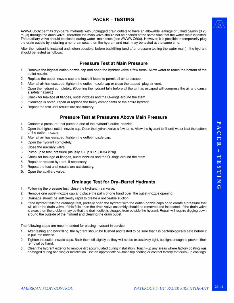
PACER − TESTING
AWWA C502 permits dry−barrel hydrants with unplugged drain outlets to have an allowable leakage of 5 fluid oz/min (0.25mL/s) through the drain valve. Therefore the main valve should not be opened at the same time that the water main is tested.The auxiliary valve should be closed during water−main tests (see AWWA C600). However, it is possible to temporarily plugthe drain outlets by installing a no−drain seat, then the hydrant and main may be tested at the same time.
After the hydrant is installed and, when possible, before backfilling (and after pressure testing the water main), the hydrantshould be tested as follows:
Pressure Test at Main Pressure1. Remove the highest outlet−nozzle cap and open the hydrant valve a few turns. Allow water to reach the bottom of the
outlet nozzle.2. Replace the outlet−nozzle cap and leave it loose to permit all air to escape.3. After all air has escaped, tighten the outlet−nozzle cap or close the tapped−plug air vent.4. Open the hydrant completely. (Opening the hydrant fully before all the air has escaped will compress the air and cause
a safety hazard.)5. Check for leakage at flanges, outlet nozzles and the O−rings around the stem.6. If leakage is noted, repair or replace the faulty components or the entire hydrant.7. Repeat the test until results are satisfactory.
Pressure Test at Pressures Above Main Pressure1. Connect a pressure−test pump to one of the hydrant’s outlet−nozzles.2. Open the highest outlet−nozzle cap. Open the hydrant valve a few turns. Allow the hydrant to fill until water is at the bottom
of the outlet− nozzle.3. After all air has escaped, tighten the outlet−nozzle cap.4. Open the hydrant completely.5. Close the auxiliary valve.6. Pump up to test pressure (usually 150 p.s.i.g. [1034 kPa]).7. Check for leakage at flanges, outlet nozzles and the O−rings around the stem.8. Repair or replace hydrant, if necessary.9. Repeat the test until results are satisfactory.
10. Open the auxiliary valve.
Drainage Test for Dry−Barrel Hydrants1. Following the pressure test, close the hydrant main valve.2. Remove one outlet−nozzle cap and place the palm of one hand over the outlet−nozzle opening.3. Drainage should be sufficiently rapid to create a noticeable suction.4. If the hydrant fails the drainage test, partially open the hydrant with the outlet−nozzle caps on to create a pressure that
will clear the drain valve. If this fails, then the drain valve assembly should be removed and inspected. If the drain valveis clear, then the problem may be that the drain outlet is plugged from outside the hydrant. Repair will require digging downaround the outside of the hydrant and clearing the drain outlet.
The following steps are recommended for placing hydrant in service:
1. After testing and backfilling, the hydrant should be flushed and tested to be sure that it is bacteriologically safe before itis put into service.
2. Tighten the outlet−nozzle caps. Back them off slightly so they will not be excessively tight, but tight enough to prevent theirremoval by hand.
3. Clean the hydrant exterior to remove dirt accumulated during installation. Touch−up any areas where factory coating wasdamaged during handling or installation. Use an appropriate oil−base top coating or contact factory for touch−up coatings.
WATEROUS 5−1/4" PACER FIRE HYDRANT2B−12 AMERICAN FLOW CONTROL
PACER − OPERATION
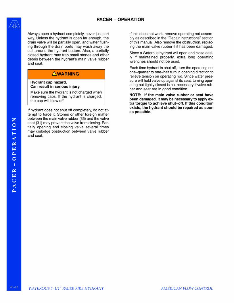
Always open a hydrant completely, never just partway. Unless the hydrant is open far enough, thedrain valve will be partially open, and water flush-ing through the drain ports may wash away thesoil around the hydrant bottom. Also, a partiallyclosed hydrant may trap small stones and otherdebris between the hydrant’s main valve rubberand seat.
WARNING!
Hydrant cap hazard.Can result in serious injury.
Make sure the hydrant is not charged whenremoving caps. If the hydrant is charged,the cap will blow off.
If hydrant does not shut off completely, do not at-tempt to force it. Stones or other foreign matterbetween the main valve rubber (35) and the valveseat (31) may prevent the valve from closing. Par-tially opening and closing valve several timesmay dislodge obstruction between valve rubberand seat.
If this does not work, remove operating rod assem-bly as described in the “Repair Instructions” sectionof this manual. Also remove the obstruction, replac-ing the main valve rubber if it has been damaged.
Since a Waterous hydrant will open and close easi-ly if maintained properly, extra long operatingwrenches should not be used.
Each time hydrant is shut off, turn the operating nutone−quarter to one−half turn in opening direction torelieve tension on operating rod. Since water pres-sure will hold valve up against its seat, turning oper-ating nut tightly closed is not necessary if valve rub-ber and seat are in good condition.
NOTE: If the main valve rubber or seat havebeen damaged, it may be necessary to apply ex-tra torque to achieve shut−off. If this conditionexists, the hydrant should be repaired as soonas possible.

P A
C E
R − M
A I N
T E
N A
N C
E
WATEROUS 5−1/4" PACER FIRE HYDRANT2B−13
AMERICAN FLOW CONTROL
PACER − MAINTENANCE
The ease of operation and the frequency of repairs depends on the condition of the water system and the mainte-nance given. Dirt, gravel and other foreign material in the water system may prevent the hydrant from closing ordraining properly, or may damage the main valve. Under most operating conditions, the following recommendedsemi−annual lubrication and inspection is the only maintenance required.
Inspection1. Every spring and fall, open hydrant completely
and let water run for several minutes. Open andclose valve to make sure it works properly, andcheck for leaks.
2. After the valve is closed, the water in the hydrantshould drain rapidly. If it does not, the drain portsmay be clogged. To clear drain ports, install nozzlecap, and tighten until water tight, then open hy-drant two or three turns for several minutes. Thiswill leave drain port partially open and permit wa-ter pressure to wash out the obstruction. If thismethod is unsuccessful, remove the operating rodassembly and clean the drain mechanism. If nei-ther of above methods permits water to drain, it in-dicates that the drainage area around the hydrantbase should be rebuilt.
Lubrication1. Oil Reservoir Hydrants:
Remove oil level plug and check oil level.Add oil to the level of the plug if necessary.
2. Non−Oil Reservoir Hydrants:
Remove screw from operating nut, andadd approximately one tablespoon of oilthrough opening. Replace screw.
3. Remove all nozzle caps, clean rust or cor-rosion from threads of nozzles and caps,and replace cap gaskets if necessary. Ap-ply a light coat of grease to nozzle threadsbefore replacing cap.
Lubricants
The recommended lubricants for the Pacer hydrant are as follows:
OilWhere oil is specified in these instructions, use whitemineral oil USP (Mobil Whiterex 425 or equal).
Grease
Where grease is specified, use Mystik�FG−2 Food Machinery Grease.

WATEROUS 5−1/4" PACER FIRE HYDRANT2B−14 AMERICAN FLOW CONTROL
PACER − TROUBLESHOOTING GUIDE
PROBLEM SOLUTION1. Operating nut turns freely but hydrant does not
open.1. Check rod coupling and replace if broken.
2. Hydrant will not shut off. 2. Check to make sure hydrant is either fully open orfully closed. When the hydrant is partially open,flow through the drain will occur. If hydrant has notbeen left partially open, use a listening device todetermine if water is passing through the main val-ve. If water is passing through the main valve, trythe following:
a. Remove nozzle cap and fully open valve toflush foreign objects from the hydrant barrel.
b. After flushing for several minutes, close hy-drant. Watch for several minutes to see if flowstops. Place hand over open hose nozzle; suc-tion should be felt indicating hydrant is nolonger leaking and drains are working prop-erly.
c. If flow continues or the hydrant does not drain,an object is trapped in or has damaged themain valve rubber. Follow the seat removalinstructions to replace the valve.
3. Operating nut is extremely hard to turn. 3. For hydrants with an oil reservoir, remove oil levelplug and add oil, if necessary. For hydrants with nooil reservoir, remove flat head screw on operatingnut and add mineral oil or similar lubricant. Ifhydrant remains hard to operate, check for dam-aged thrust bushings. If problem persists, removevalve seat and flush hydrant thoroughly.
4. Water is leaking around nozzles. 4. Remove nozzle cap and replace nozzle gasket.Tighten cap and check for leaks. If leaking contin-ues, the nozzle seal may need repair or replace-ment. Hydrants with casting dates prior to 1982used leaded−in nozzles. Hydrants with castingdates of 1982 or later use leaded−in or mechani-cally attached nozzles. On mechanically attachednozzles, remove the nozzle retainer and replacethe O−ring behind the retainer. Leaded−in nozzlesdo not use retainers and must be recaulked if leak-ing.
5. Hydrant will not drain properly. 5. Check plate identifying hydrant as a ‘‘NO DRAIN’’model requiring it to be pumped after use. If thehydrant has drains, flush hydrant to be sure noth-ing is trapped in drains. To do this, open hydrantslowly, two or three turns with caps firmly in place,then close slowly. Repeat several times. If thisdoes not solve the problem remove hydrant seatassembly and check bronze drain plunger for da-mage. If no problems are found, excavate hydrantto see if concrete or other materials have blockedthe drain.
P A
C E
R − I D
E N
T I F
Y I N
G V
A R
I A T
I O N
S / R
E P
A I R
P A
R T
S
WATEROUS 5−1/4" PACER FIRE HYDRANT2B−15
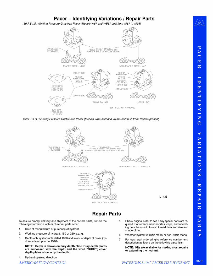
150 P.S.I.G. Working Pressure Gray Iron Pacer (Models W67 and WB67 built from 1967 to 1998)
250 P.S.I.G. Working Pressure Ductile Iron Pacer (Models W67−250 and WB67−250 built from 1996 to present)
IL1438
AMERICAN FLOW CONTROL
Pacer − Identifying Variations / Repair Parts
Repair PartsTo assure prompt delivery and shipment of the correct parts, furnish thefollowing information with each repair parts order.
1. Date of manufacture or purchase of hydrant.
2. Working pressure of hydrant, 150 or 250 p.s.i.g.
3. Depth of bury (hydrants dated 1976 and later); or depth of cover (hy-drants dated prior to 1976).
NOTE: Depth is shown on bury depth plate. Bury depth platesare embossed with the depth and the word ‘‘BURY”; coverdepth plates show only the depth.
4. Hydrant opening direction.
5. Check original order to see if any special parts are re-quired. For replacement nozzles, caps, and operat-ing nuts, be sure to furnish thread data and size andshape of nut.
6. Whether hydrant is traffic model or non−traffic model.
7. For each part ordered, give reference number anddescription as found on the following parts lists.
NOTE: Kits are available for making most repairsor extending the hydrant.

WATEROUS 5−1/4" PACER FIRE HYDRANT2B−16
P A
R T
S
L I
S T
− 2
5 0
P.
S. I
. G.
R A
T E
D
D U
C T
I L
E
I R
O N
P
A C
E R
AMERICAN FLOW CONTROL
Parts List − 250 P.S.I.G. Rated Ductile Iron Pacer
Traffic Model WB67−250 and Non−Traffic Model W67−250

P A
R T
S L
I S
T −
2 5
0 P
. S. I
. G. R
A T
E D
D U
C T
I L
E I
R O
N P
A C
E R
WATEROUS 5−1/4" PACER FIRE HYDRANT2B−17
AMERICAN FLOW CONTROL
Parts List − 250 P.S.I.G. Rated Ductile Iron PacerTraffic Model WB67−250 and Non−Traffic Model W67−250
REF NO. DESCRIPTION MATERIAL3 O−ring (Lower valve seat), 5−5/8 x 5−7/8 Buna−N5 Lower standpipe gasket Neoprene6A Hex hd bolt, 5/8−11 x 3−3/4 in. Zinc plated steel6B Hex hd bolt, 5/8−11 x 3 in. Zinc plated steel6C Hex nut, 5/8−11 Zinc plated steel7 Drain plunger Red brass8 Cotter pin, 1/4 x 1−1/2 in. Stainless steel9A, 9B Nozzle cap chain, single or double Zinc−plated steel
10 Nozzle cap, hose or pumper Ductile iron11 Cap gasket, hose or pumper Neoprene12 Nozzle, hose or pumper Brass16 Flat hd screw, 1/4−20 x 1/2 in. Stainless steel17 Operating nut (one−piece) Bronze17A Lower operating nut Bronze17B Upper operating nut Ductile iron**25 Rod bushing Red brass28 Rod (non−Traffic model) Steel rod29 Lower standpipe (Traffic model) Centrifugally cast ductile iron pipe*29 Standpipe (non−Traffic model) Centrifugally cast ductile iron pipe*30 Crossarm Bronze31 Valve seat Bronze34 Upper valve washer Ductile iron35 Main valve rubber Urethane36 Lower valve washer Ductile iron37 Hydrant bottom Ductile iron40 Upper standpipe (Traffic model) Centrifugally cast ductile iron pipe*54 Drain bushing Brass56 Support wheel Ductile iron57 O−ring (Operating nut), 1−1/2 x 1−3/4 Buna−N59 O−ring (Support wheel), 1−1/8 x 1−3/8 Buna−N60 Nozzle section Ductile iron61 Bury depth plate Aluminum61 Bury depth plate washer Zinc plated steel62B Upper standpipe flange Ductile iron63 Standpipe flange Ductile iron64 Flange lock ring Stainless steel67 Coupling sleeve (2 halves) Gray iron71 Upper rod (Traffic model) Steel rod72 Lower rod (Traffic model) Steel rod77 O−ring (Upper valve seat), 5−7/8 x 6−1/8 Buna−N81 Groove pin, 3/32 x 7/16 in. Beryllium copper82 O−ring (Upper tube seal), 2−3/8 x 2−5/8 Buna−N83 O−ring (Lower tube seal), 1−7/8 x 2−1/8 Buna−N84 Support wheel gasket Buna−N85 Support tube Ductile iron86 Stop nut, 1”− 8 Zinc plated steel87 Coupling nut, 1/2−20 Brass88 Coupling stud, 1/2−20 x 2−9/16 in. Stainless steel89 Nozzle section bushing Brass90 Thrust ring Teflon92 Upper standpipe gasket Neoprene97 Valve seat insert Bronze99 Pipe plug, 1/4 NPT Brass
101 Weathershield nut Ductile iron102 Spirol pin, hvy, 1/4 x 2−1/4 in. Stainless steel113 Breakable flange Ductile iron116 O−ring (pumper nozzle), 5−1/4 x 5−3/4 Buna−N117 Pumper nozzle retainer Ductile iron118 O−ring (hose nozzle), 3−1/4 x 3−5/8 Buna−N119 Hoze nozzle retainer Ductile iron162 Weathershield nut gasket Nitrile163 Nozzle, pumper, Storz (with cap and gasket) Bronze and Aluminum164 Nozzle cap, pumper, Storz Aluminum165 Cap gasket, pumper, Storz Buna−N173 Valve seat insert Bronze174 Valve seat insert gasket Nitrile176 Stud, 5/8−11 x 5.650 Stainless steel*AWWA Standard C151 (ANSI A21.51)**Bronze is optional on some nut sizes.

WATEROUS 5−1/4" PACER FIRE HYDRANT2B−18
P A
R T
S
L I
S T
− 1
5 0
P.
S. I
. G.
R A
T E
D
G R
A Y
I
R O
N
P A
C E
R
AMERICAN FLOW CONTROL
Parts List − 150 P.S.I.G. Rated Gray Iron Pacer
Traffic Model WB67 and Non−Traffic Model W67

P A
R T
S L
I S T
− 1 5 0 P . S
. I. G. R
A T
E D
G R
A Y
I R O
N P
A C
E R
WATEROUS 5−1/4" PACER FIRE HYDRANT2B−19
AMERICAN FLOW CONTROL
Parts List − 150 P.S.I.G. Rated Gray Iron PacerTraffic Model WB67 and Non−Traffic Model W67
REF NO. DESCRIPTION MATERIAL3 O−ring (Lower valve seat), 5−5/8 x 5−7/8 Buna−N5 Lower standpipe gasket Neoprene6 Hex hd bolt, 5/8−11 x 3 in. Zinc plated steel6A Hex hd bolt, 5/8−11 x 3−3/4 in. Zinc plated steel6B Hex hd bolt, 5/8−11 x 3 in. Zinc plated steel6C Hex nut, 5/8−11 Zinc plated steel7 Drain plunger Red brass8 Cotter pin, 1/4 x 1−1/2 in. Stainless steel9A, 9B Nozzle cap chain, single or double Zinc−plated steel
10 Nozzle cap, hose or pumper*** Gray iron, Class 3011 Cap gasket, hose or pumper Neoprene12 Nozzle, hose or pumper Brass16 Flat hd screw, 1/4−20 x 1/2 in. Stainless steel17 Operating nut (one−piece) Bronze17A Lower operating nut Bronze17B Upper operating nut*** Gray iron, Class 30**25 Rod bushing Red brass28 Rod (non−Traffic model) Steel rod29 Lower standpipe (Traffic model) Centrifugally cast ductile iron pipe*29 Standpipe (non−Traffic model) Centrifugally cast ductile iron pipe*30 Crossarm Ductile iron31 Valve seat Bronze34 Upper valve washer*** Gray iron, Class 3035 Main valve rubber Nitrile36 Lower valve washer*** Gray iron, Class 3037 Hydrant bottom*** Gray iron, Class 3040 Upper standpipe (Traffic model) Centrifugally cast ductile iron pipe*54 Drain bushing Brass56 Support wheel*** Gray iron, Class 3057 O−ring (Operating nut), 1−1/2 x 1−3/4 Buna−N59 O−ring (Support wheel), 1−1/8 x 1−3/8 Buna−N60 Nozzle section*** Gray iron, Class 3061 Bury depth plate Aluminum61 Bury depth plate washer Zinc plated steel62 Lock ring clamp Malleable iron63 Standpipe flange Ductile iron64 Flange lock ring Stainless steel67 Coupling sleeve (2 halves) Gray iron71 Upper rod (Traffic model) Steel rod72 Lower rod (Traffic model) Steel rod77 O−ring (Upper valve seat), 5−7/8 x 6−1/8 Buna−N80 Thrust washer (Used until Jan., 1970) Teflon81 Groove pin, 3/32 x 7/16 in. Beryllium copper82 O−ring (Upper tube seal), 2−3/8 x 2−5/8 Buna−N83 O−ring (Lower tube seal), 1−7/8 x 2−1/8 Buna−N84 Support wheel gasket Buna−N85 Support tube*** Gray iron86 Stop nut, 1”− 8 Zinc plated steel87 Coupling nut, 1/2−20 Brass88 Coupling stud, 1/2−20 x 2−9/16 in. Stainless steel89 Nozzle section bushing Brass90 Thrust ring (Used starting Jan., 1970) Teflon92 Upper standpipe gasket Neoprene97 Valve seat insert Bronze99 Pipe plug, 1/4 NPT Brass
101 Weathershield nut Ductile iron102 Groove pin, 1/4 x 2 in. Stainless steel113 Breakable flange Ductile iron116 O−ring (Pumper nozzle), 5−1/4 x 5−3/4 Buna−N117 Pumper nozzle retainer Ductile iron118 O−ring, (Hose nozzle), 3−1/4 x 3−5/8 Buna−N119 Hose Nozzle Retainer Ductile iron*AWWA Standard C151 (ANSI 21.51)**Bronze or ductile iron optional on some nut sizes.***Ductile Iron components will be furnished in place of gray iron components when these items are ordered for repairs.

P A
C E
R −
R E
P A
I R
I
N S
T R
U C
T I
O N
S
WATEROUS 5−1/4" PACER FIRE HYDRANT2B−20 AMERICAN FLOW CONTROL
PACER − REPAIR INSTRUCTIONS
Disassembling the Hydrant
1. Close valve in water main, remove a nozzlecap, and open hydrant to make sure that wa-ter is turned off.
250 P.S.I.G. Rated Pacers (See Figure 1, Page 2B−22)
2a. At the nozzle section, remove bolts (6A),nuts (6C), and allow flange (62B) to slidedown the upper standpipe. Depth plate andwasher (61) will come off with bolts.
150 P.S.I.G. Rated Pacers (See Figure 2, Page 2B−22)
2b. At the nozzle section, remove bolts (6A),nuts (6C) and clamps (62) from underneathflange of the nozzle section (60). Depthplate and plain washer (61) will come off withbolts.
NOTE: If clamps (62) should stick under-neath the flange of the nozzle section(60), it may be necessary to drive themout.
3. Turn upper operating nut (17B) or weather-shield nut (101) in the opening direction toseparate the nozzle section (60) and thesupport (56). Remove the nozzle section.Use proper handling techniques to avoidinjury.
4. Remove operating nut (17B or 17) from thenozzle section (60). (On hydrants with wea-thershield, it is necessary to drive out pin(102) and remove weathershield (101) be-fore upper operating nut can be removed.)
NOTE: Bushing (89) is cemented innozzle section (60). Removing it is notnecessary unless it is damaged. To re-place the bushing, follow instructions onpage 2B−24.
5. Unscrew lower operating nut (17A − two−piece nuts, 17 − one−piece nut), and re-move support tube (85).
6. Unscrew hex stop nut (86) from operatingrod (28 or 71), and remove support (56).
7. Carefully lower disassembly wrench intostandpipe over operating rod, and engagelugs of valve seat (31). See Figure 3 onPage 2B−23.
CAUTION
Do not drop disassembly wrench into hydrant; itmay damage valve seat and related parts.
8. Insert a three or four foot heavy steel bar (approxi-mately 1 in. diameter) through eye of wrench, andturn in a counterclockwise direction to removecomplete operating rod and valve assembly.
9. When valve seat (31) is clear of threads in hydrantbottom (37), remove disassembly wrench and liftout operating rod assembly.
10. To disassemble lower portion of operating rod, re-move cotter pin (8).Hold rod (28 or 72) with a pipewrench or in a vise, and unscrew lower washer(36) with a 1−9/16 end wrench or suitable adjust-able wrench. (Main valve (35), upper washer (34),valve seat (31), and cross arm (30) will come offwith lower washer.) Slide drain plunger (7) fromvalve seat. Remove O−rings (3 and 77). Do not re-move groove pin (81), which guides drain plunger,unless it is damaged. See Figure 4 on Page2B−23.
Traffic Models Only11. Disassemble breakable coupling, unscrew nuts
(87), and remove rod coupling halves (67) whichjoin upper rod (71) to lower rod (72). Do not re-move studs (88) unless they are damaged.(Breakable coupling disassembly is usually notnecessary unless coupling parts are damaged.)
NOTE: When a supply of gaskets and O−ringsare available, always install new ones whenreassembling the hydrant. Clean dirt from O−ring grooves.

P A
C E
R − R
E P
A I R
I N S
T R
U C
T I O
N S
WATEROUS 5−1/4" PACER FIRE HYDRANT2B−21
AMERICAN FLOW CONTROL
PACER − REPAIR INSTRUCTIONS
Reassembling the HydrantNote: Where grease is specified, use Mystik� FG−2 Food Machinery Grease.1. Traffic Models Only: Assemble breakable coupling.
Slide rod coupling halves (67) onto the studs (88) inthe upper and lower rods (71, 72) and install couplingnuts (87).
2. If necessary, install new groove pin (81) in valve seat(31). Slide drain plunger (7) into seat with oblonghole at lower end. Grease O−ring grooves in valveseat and install O−rings (3 and 77). Be sure to re-move any twists.
3. Slide crossarm (30) and valve seat (31) on operatingrod (28 or 72). Position main valve (35) and upperwasher (34) on lower washer (36). Screw lowerwasher onto rod, engaging diamond boss on lowerwasher in matching recess in crossarm. Positionvalve seal against valve seat (35) and tighten lowerwasher with a pull of about 50 lbs on a 12 inchwrench. Tighten enough to permit installation of thecotter pin (8).
4. Coat threads of valve seat (31) with grease. Careful-ly lower assembled operating rod into standpipe untilvalve seat rests on threads in hydrant bottom.Grasping rod (28 or 71) firmly with both hands, slow-ly turn in a counterclockwise direction until threadsengage, then turn clockwise until it is hand−tight.
5. Slowly lower disassembly wrench over operating rod(28 or 71) in standpipe, and engage it with valve seat(31). Insert a 3 or 4 foot heavy steel bar through eyeof wrench and tighten valve seat securely in hydrantbottom. Remove wrench.
CAUTION
Do not exceed 200 lb−ft torque (50 lb pull on the endof a 4 ft bar). One person using a bar 3 to 4 feet longcan easily exert enough force to tighten valve seat.Further tightening may make future seat removalmore difficult.
6. Pull rod up as far as it will go (main valve will now beclosed). Hold in this position while an assistant slow-ly turns on the water.
WARNING!
To prevent serious personal injury, do not stand overrod when assistant turns on the water.
7. Visually check for possible leaks before proceedingwith the next step.
8. Grease O−ring and gasket grooves in support (56),and install O−rings (59), gaskets (84) and lower tubeseal (83). Tape threads of operating rod (28 or 71) toprotect O−rings, and install support. Remove tapefrom threads.
9. Install hex stop nut (86), turning it down toend of thread. Snug up with a torque of 30lb−ft (30 lb at end of 12 in. wrench).
10. Grease groove in upper end of support tube(85), and install upper tube seal (82). Slidetube down over operating rod (28 or 71) untilit is seated on support (56).
11. Grease threads of operating rod (28 or 71)and lower bearing surface of operating nut(17A or 17). Screw lower operating nut ontorod while centering support (56) on thestandpipe. Tighten operating nut (17A or 17)to securely clamp support (56) against up-per standpipe (40). Be sure support (56) iscentered on upper standpipe (40).
12. Grease and install Teflon thrust ring (90) andO−ring (57) in operating nut (17B or 17). Ifhydrant has a two−piece operating nut, setupper operating nut (17B) on lower operat-ing nut (17A) and engage lugs in slots.
250 P.S.I.G. Rated Pacers (See Figure 1, Page 2B−22)
13a. Carefully lower nozzle section (60) over op-erating nut (17b or 17) until it seats on sup-port (56). Rotate nozzle section (60) to de-sired position. Install bolts (6A) and nuts(6C) through flange of nozzle section andstandpipe flange (62B) and tighten fingertight. Be sure to install depth plate andwashers (61) in proper position. Make sureflange (62B) is seated properly up underflange, and tighten all bolts and nuts evenly.Tighten to 60−70 lb−ft of torque.
150 P.S.I.G. Rated Pacers (See Figure 2, Page 2B−22)
13b. Make sure lock ring (64) is properly installedin standpipe (29) or upper standpipe (40).Carefully lower nozzle section (60) over up-per operating nut (17B or 17) until it seats onsupport (56). Rotate nozzle section (60) todesired position. Install clamps (62), bolts(6A) and nuts (6C) in flange of nozzle sec-tion and tighten finger tight. Be sure to installdepth plate and washers (61) in proper posi-tion. Make sure all clamps are seated prop-erly up under flange, and tighten all boltsand nuts evenly. Tighten to 60−70 lb−ft oftorque.
14. Back off operating nut slightly to release ten-sion on operating rod. Since water pressurewill hold valve up against seat, it is not nec-essary to turn operating nut to a dead stopif the valve and seat are in good condition.
15. Lubricate hydrant per “Lubrication” portionof the “Maintenance” section.

P A
C E
R −
R E
P A
I R
I
N S
T R
U C
T I
O N
S
WATEROUS 5−1/4" PACER FIRE HYDRANT2B−22 AMERICAN FLOW CONTROL
PACER − REPAIR INSTRUCTIONS
Figure 1. Repair Diagram − 250 P.S.I.G. Rated Pacers Figure 2. Repair Diagram − 150 P.S.I.G. Rated Pacers

P A
C E
R − R
E P
A I R
I N S
T R
U C
T I O
N S
WATEROUS 5−1/4" PACER FIRE HYDRANT2B−23
AMERICAN FLOW CONTROL
PACER − REPAIR INSTRUCTIONS
Figure 3. Rod Removal Figure 4. Rod Disassembly

P A
C E
R −
R E
P A
I R
I
N S
T R
U C
T I
O N
S
WATEROUS 5−1/4" PACER FIRE HYDRANT2B−24
Figure 5. Nozzle Section Bushing Replacement
AMERICAN FLOW CONTROL
PACER − REPAIR INSTRUCTIONS
Nozzle Section Bushing Replacement
1. Remove the old bushing. Prior to mid −1988,a nylon bushing was used. Starting mid−1988,a brass bushing was used.
Nylon Bushing: Peel out with a sharp knifeblade.
Brass Bushing: Peel out with a sharp chisel.
2. Clean any rust or paint build−up from theinside of the bore. An abrasive sandingdrum, turned with a battery−operated drillworks well. An alternative method is to re-move any rust or paint using a large half−round file. After cleaning, bare metal shouldbe visible in the bore. To check whether thebore has been cleaned to the proper size,partially insert the bushing into the bore fromthe top of the nozzle section with only slightforce from your hand. About one half of thelength of the bushing should fit into the borebefore it becomes tight.
3. Apply 1099 Scotch−Grip Adhesive/Seal-ant (Waterous Part No. V 3405): If the hy-drant was manufactured after mid−2000,install the back−up ring and O−ring onto thereplacement bushing as shown in the detaildrawing. If the hydrant was manufacturedbefore mid−2000, remove the back−up ringand O−ring from the replacement bushingand discard. Place the bushing onto thebushing driver and apply a thin, even
coating of adhesive/sealant on the outside diameterof the bushing. Apply a thin coating of adhesive/seal-ant to the inside surface of the bore in the nozzle sec-tion and let both parts dry for several minutes. Thelayers of adhesive should be mostly dry to the touch,with a slightly “tacky” surface.
4. Drive in the Bushing: Using the Bushing Driver (Wa-terous Part No. 72452) and a hammer, drive the bush-ing into the bore from the inside of the nozzle section.Be sure to drive the bushing until the flange is seatedagainst the counter bore in the nozzle section. Thebushing driver should withdraw from the inside of theinstalled bushing without resistance. If resistance isfelt, the rust or paint was not adequately cleaned fromthe nozzle section bore.
5. Prepare the Operating Nut: Remove the old O−ringseal (57) and the Thrust Ring (90) or Thrust Washer(80) from the operating nut (17 or 17B). Inspect thesurfaces of the operating nut where the seal andthrust ring or washer were located and remove anypaint or rust from the surface using a file or abrasiveemery cloth. With the O−ring removed, insert the op-erating nut into the bore from the top of the nozzlesection to test the fit of the operating nut in the newlyinstalled bushing. The nut should turn freely. If not,carefully sand or file the inside diameter of the bush-ing until the nut will turn freely in the bore. Install thenew O−ring seal (57) and the Thrust Ring (90) orThrust Washer (80) onto the operating nut (17 or17B).
P A
C E
R − T
R A
F F
I C D
A M
A G
E R
E P
A I R
WATEROUS 5−1/4" PACER FIRE HYDRANT2B−25
AMERICAN FLOW CONTROL
PACER − TRAFFIC DAMAGE REPAIR
Introduction
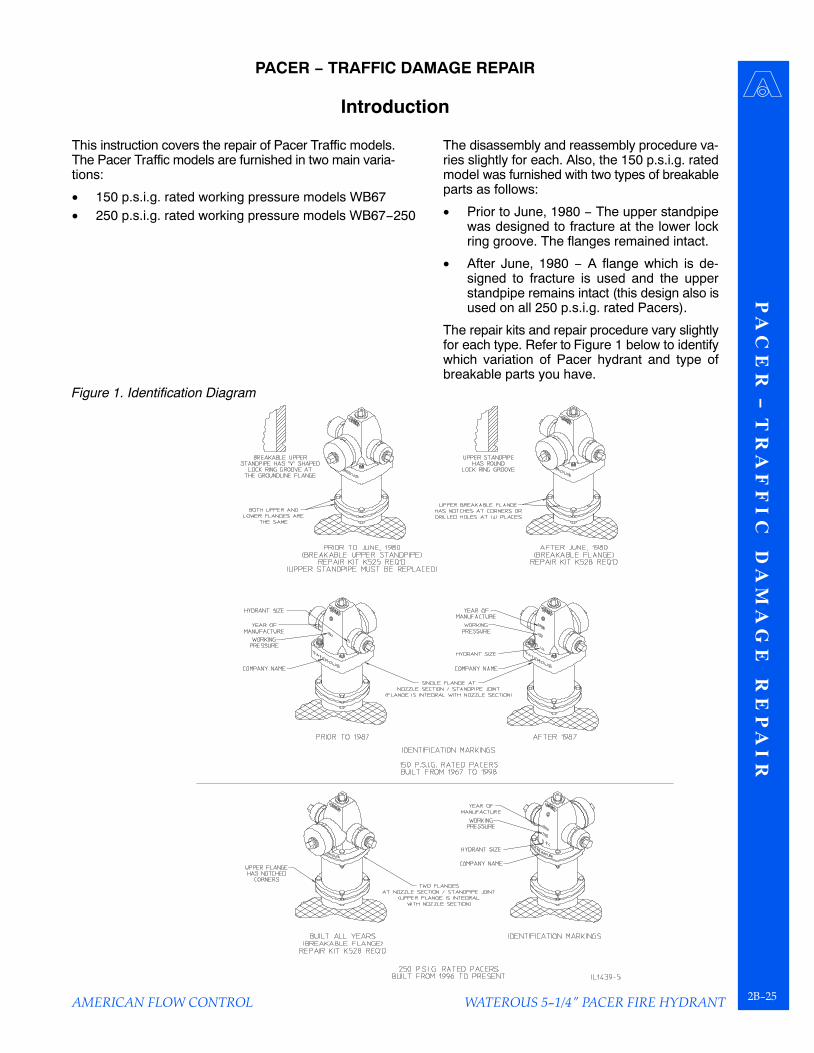
This instruction covers the repair of Pacer Traffic models.The Pacer Traffic models are furnished in two main varia-tions:
• 150 p.s.i.g. rated working pressure models WB67• 250 p.s.i.g. rated working pressure models WB67−250
The disassembly and reassembly procedure va-ries slightly for each. Also, the 150 p.s.i.g. ratedmodel was furnished with two types of breakableparts as follows:
• Prior to June, 1980 − The upper standpipewas designed to fracture at the lower lockring groove. The flanges remained intact.
• After June, 1980 − A flange which is de-signed to fracture is used and the upperstandpipe remains intact (this design also isused on all 250 p.s.i.g. rated Pacers).
The repair kits and repair procedure vary slightlyfor each type. Refer to Figure 1 below to identifywhich variation of Pacer hydrant and type ofbreakable parts you have.
Figure 1. Identification Diagram

P A
C E
R −
T R
A F
F I
C
D A
M A
G E
R
E P
A I
R
WATEROUS 5−1/4" PACER FIRE HYDRANT2B−26
150 P.S.I.G. Rated Working Pressure Pacer Using Repair Kits K525 or K528
Pacer − Traffic Damage Repair
AMERICAN FLOW CONTROL
Note: Where grease is specified, use Mystik�FG−2 Food Machinery Grease.
150 P.S.I.G. Rated Pacers (See Figure 2, Page 2B−27)
1. At the ground line, remove bolts (6B) andnuts (6C) which attach the upper and lowerflanges. Discard the gasket, nuts and bolts.
Note: If top of the hydrant is completelybroken away from the lower portion ofthe hydrant, step 1 may not be necessary.
2. At the nozzle section, remove bolts (6A),nuts (6C) and clamps (62) from underneaththe flange of the nozzle section (60). Depthplate and plain washer (61) will come off withbolts.
Note: If clamps (62) should stick under-neath the flange of the nozzle section(60), it may be necessary to drive themout.
3. If the breakable upper standpipe is fractured(hydrants built prior to June, 1980), discardupper standpipe (40) and the lower flange.A new upper standpipe with a breakableflange are furnished in kit K525.
4. Turn upper operating nut (17B) or weather-shield nut (101) in the opening direction toseparate the nozzle section (60) and thesupport (56). Remove the nozzle section,lifting upwards. Use proper handling tech-niques to avoid injury.
5. Remove operating nut (17B or 17) from thenozzle section (60). (On hydrants with wea-thershield, it is necessary to drive out pin(102) and remove weathershield (101) be-fore upper operating nut can be removed.)
Note: Bushing (89) is cemented in nozzlesection (60). Removing it is not neces-sary unless it is damaged. If replacementis necessary, see Page 2B−24.
6. Unscrew lower operating nut (17A − two−piece nuts, 17 − one−piece nut), and removesupport tube (85).
7. Unscrew hex stop nut (86) from operatingrod (71), and remove support (56).
8. Remove nuts (87) and rod coupling halves(67) from upper and lower rods (71 & 72).Carefully check upper rod (71) to make sureit is not bent more than 1/8 in. out of straight-ness. Straighten or replace if necessary.Also check studs (88) for thread damage orbending which will prevent the installation ofnew coupling halves. Replace studs if nec-essary.
9. Position upper rod (71) over lower rod (72) and installnew coupling halves (67). Install nuts (87) and tight-en securely.
Hydrants built prior to June, 1980 (K525)
10a. Slide breakable flange (113) over lower end of thenew upper standpipe (40). (The lower end has thelock ring groove 3/8 in. from the end.) Install lockrings (64) in grooves on the upper standpipe. (Besure flange is orientated so that the larger ID of theflange engages the lock ring properly.) See Figure 3on Page 2B−27.
Hydrants built after to June, 1980 (K528)
10b. Remove lock rings (64) from the bottom of the upperstandpipe (40). Remove old breakable flange (113)from the upper standpipe if it is still attached (in mostcases, it will fracture and disengage itself from theupper standpipe). Slide new breakable flange (113)over the upper standpipe (40) (orient flange so thatthe larger ID of the flange will point down and proper-ly engage the lock ring). See Figure 3. Install lockring (64) in the bottom groove of the upper standpipe(40). Slide flange (113) down and over the lock ring(64).
11. Place new gasket (92) on the lower standpipe withthe lip pointing down. Position the upper standpipe(40) on the lower standpipe and install bolts (6B) thruflanges (113) and (63). Install nuts (6C) and tightenthe four bolts evenly. Tighten to 60−70 lb−ft of torque.
Note: Be sure to install the upper standpipe cor-rectly. The groove at the top must be 3/4 in. fromthe end. The groove at the bottom must be 3/8 in.from the end. Also, the breakable flange (113)must be at the bottom (groundline) end. SeeFigure 3 on Page 2B−27.
12. Grease O−ring and gasket grooves in support (56),and grease O−rings (59), gaskets (84) and lowertube seal (83). Tape threads of operating rod (71) toprotect O−rings. Install support (56) onto operatingrod (71), being careful not to damage O−rings on op-erating rod threads. Remove tape from threads.
13. Install hex stop nut (86), threading it down to end ofthread. Snug up with a torque of 30 lb−ft (30 lb at endof 12 in. wrench).
14. Grease O−ring in upper end of support tube (85).Slide tube down over operating rod (71) until it isseated on support (56).
15. Grease threads of operating rod (71) and lower bear-ing surface of operating nut (17A or 17). Screw loweroperating nut onto rod while centering support (56)on the standpipe. Tighten operating nut (17A or 17)to securely clamp support (56) against upper stand-pipe (40). Be sure support (56) is centered on upperstandpipe (40).

P A
C E
R − T
R A
F F
I C D
A M
A G
E R
E P
A I R
WATEROUS 5−1/4" PACER FIRE HYDRANT2B−27
AMERICAN FLOW CONTROL
Pacer − Traffic Damage Repair150 P.S.I.G. Rated Working Pressure Pacer Using Repair Kits K525 or K528
16. Grease and install Teflon thrust ring (90) and O−ring(57) in upper operating nut (17B or 17). If hydrant hasa two−piece operating nut, set upper operating nut(17B) on lower operating nut (17A) and engage lugsin slots.
17. Make sure lock ring (64) is properly installed in theupper standpipe (40). Carefully lower nozzle section(60) over upper operating nut (17B or 17) until it seatson support (56). Rotate nozzle section (60) to desiredposition. Install clamps (62), bolts (6A) and nuts (6C)in flange of nozzle section and tighten finger tight. Besure to install depth plate and washers (61) in properposition. Make sure all clamps are seated properlyup under nozzle section flange and tighten all boltsand nuts evenly. Tighten to 60−70 lb−ft of torque.
18. Back off operating nut slightly to release ten-sion on operating rod. Since water pressurewill hold valve up against seat, it is not nec-essary to turn operating nut to a dead stopif the valve and seat are in good condition.
19. Lubricate hydrant as shown in Figure 4.
Note: When a supply of gaskets and O−rings are available, always install newones when reassembling the hydrant.Clean dirt from O−ring grooves.
Figure 2. 150 P.S.I.G. Traffic Repair Figure 3. Upper Standpipe/Breakable Flange Orientation
Figure 4. Lubrication Detail
Oil Reservoir Hydrants: Removal oil level plug. Add oilto the level of the plug. Use white mineral oil USP Mo-bil Whiterex 425 or equal.
Non−Oil Reservoir Hydrants: Remove screw from oper-ating nut and add approximately one tablespoon of oilthrough opening. Replace screw. Use white mineral oilUSP Mobil Whiterex 425 or equal.
Remove all nozzle caps, clean rust or corrosion fromthreads of nozzles and caps. Replace cap gaskets if nec-essary. Apply a light coat of grease to nozzle threads be-fore replacing cap. Use Mystik� FG−2 Food MachineryGrease.
1.
2.

P A
C E
R −
T R
A F
F I
C
D A
M A
G E
R
E P
A I
R
WATEROUS 5−1/4" PACER FIRE HYDRANT2B−28
250 P.S.I.G. Rated Working Pressure Pacer Using Repair Kit K528
Pacer − Traffic Damage Repair
AMERICAN FLOW CONTROL
Note: Where grease is specified, use Mystik�FG−2 Food Machinery Grease.
250 P.S.I.G. Rated Pacers (See Figure 5, Page 2B−29)
1. At the groundline, remove bolts (6B) andnuts (6C) which attach the upper and lowerflanges. Discard the gasket, nuts and bolts.
Note: If top of the hydrant is completelybroken away from the lower portion ofthe hydrant, step 1 may not be neces-sary.
2. At the nozzle section, remove bolts (6A),nuts (6C) and allow flange (62B) to slidedown the upper standpipe. Depth plate andplain washer (61) will come off with bolts.
3. Turn upper operating nut (17B) or weather-shield nut (101) in the opening direction sep-arate the nozzle section (60) and the sup-port (56). Remove the nozzle section. Useproper handling techniques to avoid in-jury.
4. Remove operating nut (17B or 17) from thenozzle section (60). (On hydrants with wea-thershield, it is necessary to drive out pin(102) and remove weathershield (101) be-fore upper operating nut can be removed.)
Note: Bushing (89) is cemented in nozzlesection (60). Removing it is not neces-sary unless it is damaged. If replace-ment is necessary, see Page 2B−24.
5. Unscrew lower operating nut (17A − two−piece nuts, 17 − one−piece nut), and re-move support tube (85).
6. Unscrew hex stop nut (86) from operatingrod (71), and remove support (56).
7. Remove coupling nuts (87) and sleeves (67)from upper and lower rods (71 & 72). Care-fully check upper rod (71) to make sure it isnot bent more than 1/8 in. out of straight-ness. Straighten or replace if necessary.Also check studs (88) for thread damage orbending which will prevent the installation ofa new coupling. Replace studs if necessary.
8. Position upper rod (71) over lower rod (72)and install new coupling halves (67). Installnuts (87) and tighten securely.
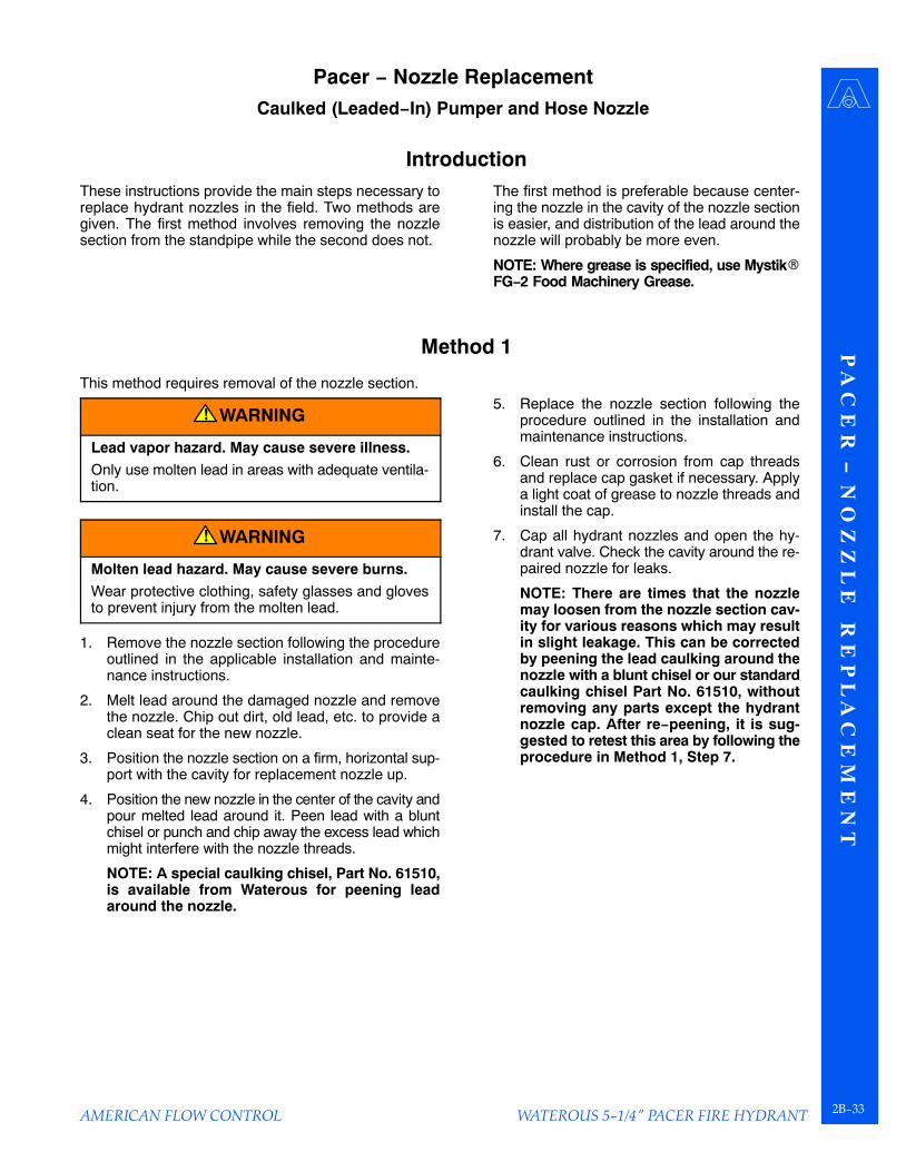
9. Remove lock ring (64) from the bottom of the upperstandpipe (40). Remove old breakable flange (113)from the upper standpipe if it is still attached (in mostcases, it will fracture and disengage itself from theupper standpipe). Slide new breakable flange (113)over the upper standpipe (40). Orient flange so thatthe larger ID of the flange will point down and proper-ly engage the lock ring. Install lock ring (64) in thebottom groove of the upper standpipe (40). Slideflange (113) down and over the lock ring (64). SeeFigure 6, on Page 2B−29.
10. Place new gasket (92) on the lower standpipe withthe lip pointing down. Position the upper standpipe(40) on the lower standpipe and install bolts (6B) thruflanges (113) and (63). Install nuts (6C) and tightenthe four bolts evenly. Tighten to 60−70 lb−ft of torque.
11. Grease O−ring and gasket grooves in support (56),and grease O−rings (59), gaskets (84) and lowertube seal (83). Tape threads of operating rod (71) toprotect O−rings. Install support (56) onto operatingrod (71), being careful not to damage O−rings on op-erating rod threads. Remove tape from threads. SeeFigure 6, on Page 2B−29.
12. Install hex stop nut (86), threading it down to end ofthread. Snug up with a torque of 30 lb−ft (30 lb at endof 12 in. wrench).
13. Grease O−ring in upper end of support tube (85).Slide tube down over operating rod (71) until it isseated on support (56).
14. Grease threads of operating rod (71) and lower bear-ing surface of operating nut (17A or 17). Screw loweroperating nut onto rod while centering support (56)on the standpipe. Tighten operating nut (17A or 17)to securely clamp support (56) against upper stand-pipe (40). Be sure support (56) is centered on upperstandpipe (40).
15. Grease and install Teflon thrust ring (90) and O−ring(57) in upper operating nut (17B or 17). If hydrant hasa two−piece operating nut, set upper operating nut(17B) on lower operating nut (17A) and engage lugsin slots.
Note: Be sure to install the upper standpipe cor-rectly. The groove at the top must be 3/4 in. fromthe end. The groove at the bottom must be 3/8 in.from the end. Also, the breakable flange (113)must be at the bottom (groundline) end of the up-per standpipe. See Figure 6, on Page 2B−29.
P A
C E
R − T
R A
F F
I C D
A M
A G
E R
E P
A I R
WATEROUS 5−1/4" PACER FIRE HYDRANT2B−29
AMERICAN FLOW CONTROL
Pacer − Traffic Damage Repair250 P.S.I.G. Rated Working Pressure Pacer Using Repair Kit K528
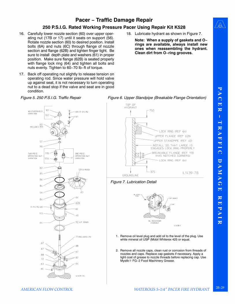
16. Carefully lower nozzle section (60) over upper oper-ating nut (17B or 17) until it seats on support (56).Rotate nozzle section (60) to desired position. Installbolts (6A) and nuts (6C) through flange of nozzlesection and flange (62B) and tighten finger tight. Besure to install depth plate and washers (61) in properposition. Make sure flange (62B) is seated properlywith flange lock ring (64) and tighten all bolts andnuts evenly. Tighten to 60−70 lb−ft of torque.
17. Back off operating nut slightly to release tension onoperating rod. Since water pressure will hold valveup against seat, it is not necessary to turn operatingnut to a dead stop if the valve and seat are in goodcondition.
18. Lubricate hydrant as shown in Figure 7.
Note: When a supply of gaskets and O−rings are available, always install newones when reassembling the hydrant.Clean dirt from O−ring grooves.
Figure 5. 250 P.S.I.G. Traffic Repair Figure 6. Upper Standpipe (Breakable Flange Orientation)
Figure 7. Lubrication Detail
Remove oil level plug and add oil to the level of the plug. Usewhite mineral oil USP (Mobil Whiterex 425 or equal.
Remove all nozzle caps, clean rust or corrosion from threads ofnozzles and caps. Replace cap gaskets if necessary. Apply alight coat of grease to nozzle threads before replacing cap. UseMystik� FG−2 Food Machinery Grease.
1.
2.

P A
C E
R −
N O
Z Z
L E
R
E P
L A
C E
M E
N T
WATEROUS 5−1/4" PACER FIRE HYDRANT2B−30 AMERICAN FLOW CONTROL
PACER − NOZZLE REPLACEMENT
Mechanically Attached NozzlesMechanically Attached method (see Figure 1) −A retainer is threaded onto the nozzle, trappingan O−ring against the nozzle section and provid-ing a water tight seal. This method is used on allnewer versions of Waterous Pacer hydrants.
Waterous has wrenches available for removingand installing retainers as follows.
• For Pumper Nozzles: Part No. 81420• For 5” Storz
Pumper Nozzles: Part No. 82766• For Hose Nozzles: Part No. 72094
Figure 1. Mechanically Attached Nozzles
Caulked (Leaded−In) NozzlesCaulked (Leaded−In) method (see Figure 2) −Molten lead is poured into the void area betweenthe nozzle and nozzle section which solidifiesand creates a water tight seal. This method wasused on older versions of Waterous Pacer hy-drants.
Figure 2. Caulked (Leaded−In) Nozzles

P A
C E
R − N
O Z
Z L
E R
E P
L A
C E
M E
N T
WATEROUS 5−1/4" PACER FIRE HYDRANT2B−31
AMERICAN FLOW CONTROL
Pacer − Nozzle ReplacementMechanically Attached Pumper Nozzle
Removal1. Remove cap.
2. Place wrench on the retainer so it engages therounded protrusions and unthread from nozzle.
Removal of the 5−inch Storz hydrant nozzle requiresthe use of the hinged pumper−nozzle retainer wrench(Waterous Part No. 82766).
3. Rotate nozzle counter−clockwise until thefour lugs on the nozzle disengage the re-cesses in the nozzle section socket whichwill allow the nozzle to be removed.
Installation1. Thread retainer onto the retainer threads of the
pumper nozzle.
2. Grease O−ring and place it over nozzle starting fromthe end with the four lugs and into the chamferrecess in the retainer.
3. Insert the nozzle/retainer/O−ring subassembly intothe socket in the nozzle section. Rotate the subas-sembly clockwise until it stops with the four lugs onthe nozzle fully engaged in the anti−rotationrecesses in the socket. If it cannot be rotated, turnthe retainer in a direction to allow the nozzle to beinserted further into the socket so the subassemblyrotates clockwise against the stops.
4. Hand tighten the retainer to press O−ring against theface of the socket.
5. Place wrench on the retainer so it engagesthe rounded protrusions, tighten firmly.
Installation of the 5−inch Storz hydrantnozzle requires the use of the hingedpumper−nozzle retainer wrench (WaterousPart No. 82766).
6. Clean rust or corrosion from cap threadsand replace cap gasket if necessary. Applya light coat of grease to the nozzle threadsand install the cap.
7. Cap all nozzles and open the hydrant valve,check the area around the repaired nozzlefor leaks.
NOTE: Where grease is specified, use-Mystik� FG−2 Food Machinery Grease.
Figure 3. Mechanically Attached Pumper Nozzle

P A
C E
R −
N O
Z Z
L E
R
E P
L A
C E
M E
N T
WATEROUS 5−1/4" PACER FIRE HYDRANT2B−32 AMERICAN FLOW CONTROL
Pacer − Nozzle ReplacementMechanically Attached 2−1/2” Hose Nozzle
Removal1. Remove cap.
2. Place wrench on the retainer so it engagesthe rounded protrusions and unthread fromnozzle.
3. Rotate nozzle counter−clockwise until the two lugson the nozzle disengage the recesses in the nozzlesection socket which will allow the nozzle to be re-moved.
Installation1. Insert hose nozzle into the socket of the
nozzle section, turn clockwise until it stopswith the two lugs on the nozzle fully engagedin the anti−rotation recesses in the socket.
2. Grease O−ring and place it over the nozzleand against the face of the socket.
3. Thread retainer onto the hose nozzle andhand tighten to press the O−ring against theface of the socket.
4. Place wrench on retainer so it engages the roundedprotrusions, and tighten firmly.
5. Clean rust or corrosion from cap threads and replacecap gasket if necessary. Apply a light coat of greaseto the nozzle threads and install the cap.
NOTE: Where grease is specified, use Mystik�FG−2 Food Machinery Grease.
Figure 4. Mechanically Attached Hose Nozzle
Chamfer recess this side
Hose nozzle
Hose nozzle seal (O−ring)
Hose nozzle retainer
Hose nozzle wrenchWaterous Part No. 72094
Cap
P A
C E
R − N
O Z
Z L
E R
E P
L A
C E
M E
N T
WATEROUS 5−1/4" PACER FIRE HYDRANT2B−33
AMERICAN FLOW CONTROL
Pacer − Nozzle ReplacementCaulked (Leaded−In) Pumper and Hose Nozzle
IntroductionThese instructions provide the main steps necessary toreplace hydrant nozzles in the field. Two methods aregiven. The first method involves removing the nozzlesection from the standpipe while the second does not.
The first method is preferable because center-ing the nozzle in the cavity of the nozzle sectionis easier, and distribution of the lead around thenozzle will probably be more even.
NOTE: Where grease is specified, use Mystik�FG−2 Food Machinery Grease.
Method 1
This method requires removal of the nozzle section.
WARNING!
Lead vapor hazard. May cause severe illness.
Only use molten lead in areas with adequate ventila-tion.
WARNING!
Molten lead hazard. May cause severe burns.
Wear protective clothing, safety glasses and glovesto prevent injury from the molten lead.
1. Remove the nozzle section following the procedureoutlined in the applicable installation and mainte-nance instructions.
2. Melt lead around the damaged nozzle and removethe nozzle. Chip out dirt, old lead, etc. to provide aclean seat for the new nozzle.
3. Position the nozzle section on a firm, horizontal sup-port with the cavity for replacement nozzle up.
4. Position the new nozzle in the center of the cavity andpour melted lead around it. Peen lead with a bluntchisel or punch and chip away the excess lead whichmight interfere with the nozzle threads.
NOTE: A special caulking chisel, Part No. 61510,is available from Waterous for peening leadaround the nozzle.
5. Replace the nozzle section following theprocedure outlined in the installation andmaintenance instructions.
6. Clean rust or corrosion from cap threadsand replace cap gasket if necessary. Applya light coat of grease to nozzle threads andinstall the cap.
7. Cap all hydrant nozzles and open the hy-drant valve. Check the cavity around the re-paired nozzle for leaks.
NOTE: There are times that the nozzlemay loosen from the nozzle section cav-ity for various reasons which may resultin slight leakage. This can be correctedby peening the lead caulking around thenozzle with a blunt chisel or our standardcaulking chisel Part No. 61510, withoutremoving any parts except the hydrantnozzle cap. After re−peening, it is sug-gested to retest this area by following theprocedure in Method 1, Step 7.

P A
C E
R −
N O
Z Z
L E
R
E P
L A
C E
M E
N T
WATEROUS 5−1/4" PACER FIRE HYDRANT2B−34 AMERICAN FLOW CONTROL
Pacer − Nozzle ReplacementCaulked (Leaded−In) Pumper and Hose Nozzle
Method 2If circumstances make removal of the nozzlesection inconvenient, this method permits instal-ling replacement nozzles without disassemblingthe hydrant. This method should normally not beused due to the following:
• Melted lead may flow unevenly around thenozzle.
• Lead may leak into the hydrant and foul thevalve parts at the bottom.
WARNING!
Lead vapor hazard. May cause severe ill-ness.
Only use molten lead in areas with adequateventilation.
WARNING!
Molten lead hazard. May cause severeburns.
Wear protective clothing, safety glasses andgloves to prevent injury from the molten lead.
1. Melt lead around the damaged nozzle and re-move the nozzle. Chip out dirt, old lead, etc., toprovide a clean seat for the new nozzle.
2. Wrap a 1/2 in. diameter bead of metal−retainingcompound around the new nozzle to seal thecavity and to hold the nozzle in position. Leavea small gap at the top of the bead to permit pour-ing in melted lead.
3. Form a V−shaped, sheet−metal trough, smallenough to enter the gap in the bead. Use thetrough to pour melted lead around the nozzle.
4. Remove the metal−retaining compound andpeen lead with a blunt chisel or punch. Chipaway excess lead which might interfere withnozzle threads.
5. Clean rust or corrosion from cap threads and re-place cap gasket if necessary. Apply a light coatof grease to nozzle threads and install the cap.
6. Cap all hydrant nozzles and open the hydrantvalve. Check the cavity around the repairednozzle for leaks.
Figure 5. Caulked (Leaded−In) Pumper and Hose Nozzle Replacement

P A
C E
R − E
X T
E N
D I N
G T
R A
F F
I C M
O D
E L
WATEROUS 5−1/4" PACER FIRE HYDRANT2B−35
AMERICAN FLOW CONTROL
PACER − EXTENDING TRAFFIC MODEL
Introduction
This instruction covers the installation of the standpipeand rod extension kit (K562) for Pacer Traffic models.Traffic Pacer models are furnished in two main variations:
• 150 p.s.i.g. rated working pressure models WB67
• 250 p.s.i.g. rated working pressure models WB67−250
The extension kit installation is identical for bothvariations; however, the disassembly and reas-sembly varies slightly. Refer to the identificationdiagram below to identify which variation of Pac-er hydrant you have.
Figure 1. Identification Diagram
Important Notes
1. Waterous recommends a new rod corresponding tothe extended bury or cover depth be installed in placeof a rod extension if the hydrants meet one or moreof the following criteria:
a. The length of the rod extension required exceeds4’−0”.
b. The hydrant has already been extended. Onlyone rod extension per hydrant is recommended.
c. 150 P.S.I.G. rated Pacers only:The depth of the extended hydrant will exceed9’−0” bury or 8’−6” cover. Depths of 9’−6” thru11’−6” bury and 9’−0” thru 11’−0” cover shouldhave a heavy duty (larger diameter) rod installed.Note that 250 PSI rated Pacers are supplied withheavy duty rods for all depths from the factory.
2. If extended depth of hydrant will exceed11’−6” bury or 11’−0” cover, a “bottom exten-sion” should be installed in place of a stand-pipe and rod extension.
3. Contact Waterous Company for appropriateparts and guidance if any of the above situa-tions exist.

P A
C E
R −
E X
T E
N D
I N
G
T R
A F
F I
C
M O
D E
L
WATEROUS 5−1/4" PACER FIRE HYDRANT2B−36
Pacer − Extending Traffic Model
AMERICAN FLOW CONTROL
Note: Where grease is specified, use Mystik�FG−2 Food Machinery Grease.
1. Closing the water main valve when installingextensions is usually not necessary. Waterpressure will keep the hydrant valve closed.
250 P.S.I.G. Rated Pacers (See Figure 2, Page 2B−37)
2a. At the nozzle section, remove bolts (6A), nuts(6C), and allow flange (62B) to slide down theupper standpipe. Depth plate and washer(61) will come off with bolts.
150 P.S.I.G. Rated Pacers (See Figure 3, Page 2B−37)
2b. At the nozzle section, remove bolts (6A), nuts(6C) and clamps (62) from underneathflange of the nozzle section (60). Depth plateand plain washer (61) will come off with bolts.
Note: If clamps (62) should stick under-neath the flange of the nozzle section (60),it may be necessary to drive them out.
3. Turn upper operating nut (17B) or weather-shield nut (101) in the opening direction toseparate the nozzle section (60) and the sup-port (56). Remove the nozzle section, liftingupwards. Use proper handling techniquesto avoid injury.
4. Remove operating nut (17B or 17) from thenozzle section (60). (On hydrants with wea-thershield, it is necessary to drive out pin(102) and remove weathershield (101) be-fore upper operating nut can be removed.)
Note: Bushing (89) is cemented in nozzlesection (60). Removing it is not neces-sary unless it is damaged. If replacementis necessary, contact the Waterous Com-pany.
5. Unscrew lower operating nut (17A − two−piece nuts, 17 − one−piece nut), and removesupport tube (85).
6. Unscrew hex stop nut (86) from operating rod(28), and remove support (56).
7. Remove bolts (6B) and nuts (6C) and lift offupper standpipe (40). Discard gasket (92),bolts (6B) and nuts (6C). Note that on 250 PSIPacers, flange (113) and (62B) will remain at-tached to the upper standpipe (40). On 150PSI Pacers, flange (113) will remain at-tached. It is not necessary to remove theseflanges. They may remain on the upperstandpipe.
8. Disassemble breakable coupling. Unscrewnuts (87) and remove rod coupling halves(67) which join the upper rod (71) to the lowerrod (72). Do not remove studs (88) unlessthey are damaged.
9. Install rod extension (74) on existing lower rod (72) us-ing extension couplings (174). Slide coupling halves(174) onto studs in rod extension (74) and lower rod(72) and install nuts (87). Note: Be sure extensioncouplings are installed at the original ground line. Re-fer to Figure 5 on Page 2B−38.
10. Install flanges (63) and lock rings (64) onto standpipeextension (45). Be sure to orient flanges properly. Re-fer to Figure 4 on Page 2B−38.
11. Install gasket (92) on existing standpipe with lip point-ing down. Install standpipe extension (45) on existingstandpipe. Install bolts (6D) and nuts (6C) thru flanges(63) and tighten finger tight. Make sure flanges (63)are seated properly on lock rings (64) and tighten allbolts and nuts evenly. Tighten to 60−70 lb− ft torque.
12. Install existing upper rod (71) onto rod extension (74)using breakable couplings (67). Slide coupling halves(67) onto studs in rod extension (74) and upper rod(71) and install nuts (87). Note: Be sure breakablecouplings are installed at the new ground line. Referto Figure 5 on Page 2B−38.
13. Install gasket (92) on standpipe extension (45) with lippointing down. Install existing upper standpipe (40) onstandpipe extension. Install bolts (6B) and nuts (6C)thru flanges (113) and (63) and tighten finger tight. Besure flanges engage lock rings (64) properly and tight-en all bolts and nuts evenly. Note that breakableflange (113) must be on on the bottom of the upperstandpipe. Also, upper standpipe (40) must beinstalled properly with the groove 3/4 in. from the endat the top and the groove 3/8 in. from the end at thebottom. Refer to Figure 5 on Page 2B−38.
14. Grease O−ring and gasket grooves in support (56),and grease O−rings (59), gaskets (84) and lower tubeseal (83). Tape threads of operating rod (71) to protectO−rings. Install support (56) onto operating rod (71),being careful not to damage O−rings on operating rodthreads. Remove tape from threads.
15. Install hex stop nut (86), turning it down to end ofthread. Snug up with a torque of 30 lb−ft (30 lb at endof 12 in. wrench).
16. Grease O−ring in upper end of support tube (85).Slide tube down over operating rod (71) until it isseated on support (56).
17. Grease threads of operating rod (71) and lower bear-ing surface of operating nut (17A or 17). Screw loweroperating nut onto rod while centering support (56) onthe standpipe. Tighten operating nut (17A or 17) to se-curely clamp support (56) against upper standpipe(40). Be sure support (56) is centered on upper stand-pipe (40).
18. Grease and install Teflon thrust ring (90) and O−ring(57) in operating nut (17B or 17). If hydrant has a two−piece operating nut, set upper operating nut (17B) onlower operating nut (17A) and engage lugs in slots.

P A
C E
R − E
X T
E N
D I N
G T
R A
F F
I C M
O D
E L
WATEROUS 5−1/4" PACER FIRE HYDRANT2B−37
AMERICAN FLOW CONTROL
Pacer − Extending Traffic Model250 P.S.I.G. Rated Pacers (See Figure 2)
19a. Carefully lower nozzle section (60) over operatingnut (17b or 17) until it seats on support (56). Rotatenozzle section (60) to desired position. Install bolts(6A) and nuts (6C) through flange of nozzle sectionand flange (62B) and tighten finger tight. Be sure toinstall depth plate and washers (61) in proper posi-tion. Also install extension plate (157) opposite thebury depth plate (see Figure 6). Make sure flange(62B) is seated properly with lock ring (64) and tight-en all bolts and nuts evenly. Tighten to 60−70 lb−ft oftorque.
150 P.S.I.G. Rated Pacers (See Figure 3)
19b. Make sure lock ring (64) is properly installed in upperstandpipe. Carefully lower nozzle section (60) overupper operating nut (17B or 17) until it seats on sup-port (56). Rotate nozzle section (60) to desired posi-tion. Install clamps (62), bolts (6A) and nuts (6C) in
flange of nozzle section and tighten fingertight. Be sure to install depth plate andwashers (61) in proper position. Also installextension plate (157) opposite the burydepth plate (see Figure 6). Make sure allclamps are seated properly up under flange,and tighten all bolts and nuts evenly. Tightento 60−70 lb−ft of torque.
20. Back off operating nut slightly to release ten-sion on operating rod. Since water pressurewill hold valve up against seat, it is not nec-essary to turn operating nut to a dead stopif the valve and seat are in good condition.
21. Lubricate hydrant as shown in Figure 7 onPage 2B−38.
Note: When a supply of gaskets and O−rings are available, always install newones when reassembling the hydrant.Clean dirt from O−ring grooves.
Figure 2. Installation Diagram − 250 P.S.I.G. Rated Pacer Figure 3. Installation Diagram − 150 P.S.I.G. Rated Pacer

P A
C E
R −
E X
T E
N D
I N
G
T R
A F
F I
C
M O
D E
L
WATEROUS 5−1/4" PACER FIRE HYDRANT2B−38 AMERICAN FLOW CONTROL
Pacer − Extending Traffic Model
Figure 4. Standpipe Extension/Flange Orientation Figure 6. Extension Plate Installation
Figure 5. Extension Parts / Existing Parts Orientation Figure 7. Lubrication Detail
Oil Reservoir Hydrants: Remove oil level plug. Add oilto the level of the plug. Use white mineral oil USP MobilWhiterex 425 or equal.
Non−Oil Reservoir Hydrants: Remove screw from operating nutand add approximately one tablespoon of oil through opening.Replace screw. Use white mineral oil USP Mobil Whiterex 425or equal.
Remove all nozzle caps, clean rust or corrosion from threads ofnozzles and caps. Replace cap gaskets if necessary. Apply alight coat of grease to nozzle threads before replacing cap. UseMystik� FG−2 Food Machinery Grease.
1.
2.

P A
C E
R − E
X T
E N
D I N
G N
O N
− T R
A F
F I C
M O
D E
L
WATEROUS 5−1/4" PACER FIRE HYDRANT2B−39
AMERICAN FLOW CONTROL
PACER − EXTENDING NON−TRAFFIC MODEL
Introduction
This instruction covers the installation of the standpipeand rod extension kit (K563) for Pacer non−Traffic mod-els. Non−Traffic Pacer models are furnished in two mainvariations:
• 150 p.s.i.g. rated working pressure models W67
• 250 p.s.i.g. rated working pressure models W67−250
The extension kit installation is identical for bothvariations; however, the disassembly and reas-sembly varies slightly. Refer to the identificationdiagram below to identify which variation of Pacerhydrant you have.
Figure 1. Identification Diagram
Important Notes1. Waterous recommends a new rod corresponding to
the extended bury or cover depth be installed inplace of a rod extension if the hydrants meet one ormore of the following criteria:
a. The length of the rod extension required ex-ceeds 4’−0”.
b. The hydrant has already been extended. Onlyone rod extension per hydrant is recommended.
c. 150 P.S.I.G rated Pacers only:The depth of the extended hydrant will exceed9’−0” bury or 8’−6” cover. Depths of 9’−6” thru11’−6” bury and 9’−0” thru 11’−0” cover shouldhave a heavy duty (larger diameter) rodinstalled. Note that 250 p.s.i.g. rated Pacers aresupplied with heavy duty rods for all depths fromthe factory.
2. If extended depth of hydrant will exceed11’−6” bury or 11’−0” cover, a “bottom exten-sion” should be installed in place of a stand-pipe and rod extension.
3. Contact Waterous Company for appropriateparts and guidance if any of the above situa-tions exist.
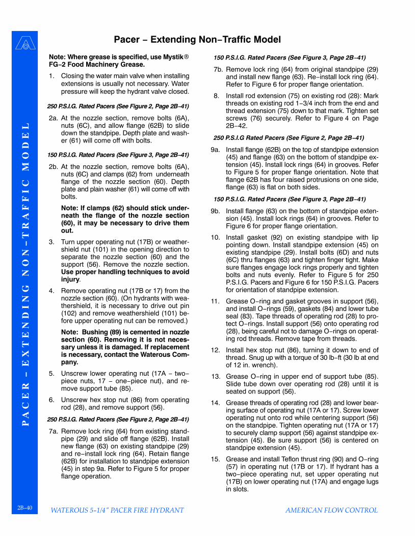
P A
C E
R −
E X
T E
N D
I N
G
N O
N −
T R
A F
F I
C
M O
D E
L
WATEROUS 5−1/4" PACER FIRE HYDRANT2B−40
Pacer − Extending Non−Traffic Model
AMERICAN FLOW CONTROL
Note: Where grease is specified, use Mystik�FG−2 Food Machinery Grease.
1. Closing the water main valve when installingextensions is usually not necessary. Waterpressure will keep the hydrant valve closed.
250 P.S.I.G. Rated Pacers (See Figure 2, Page 2B−41)
2a. At the nozzle section, remove bolts (6A),nuts (6C), and allow flange (62B) to slidedown the standpipe. Depth plate and wash-er (61) will come off with bolts.
150 P.S.I.G. Rated Pacers (See Figure 3, Page 2B−41)
2b. At the nozzle section, remove bolts (6A),nuts (6C) and clamps (62) from underneathflange of the nozzle section (60). Depthplate and plain washer (61) will come off withbolts.
Note: If clamps (62) should stick under-neath the flange of the nozzle section(60), it may be necessary to drive themout.
3. Turn upper operating nut (17B) or weather-shield nut (101) in the opening direction toseparate the nozzle section (60) and thesupport (56). Remove the nozzle section.Use proper handling techniques to avoidinjury.
4. Remove operating nut (17B or 17) from thenozzle section (60). (On hydrants with wea-thershield, it is necessary to drive out pin(102) and remove weathershield (101) be-fore upper operating nut can be removed.)
Note: Bushing (89) is cemented in nozzlesection (60). Removing it is not neces-sary unless it is damaged. If replacementis necessary, contact the Waterous Com-pany.
5. Unscrew lower operating nut (17A − two−piece nuts, 17 − one−piece nut), and re-move support tube (85).
6. Unscrew hex stop nut (86) from operatingrod (28), and remove support (56).
250 P.S.I.G. Rated Pacers (See Figure 2, Page 2B−41)
7a. Remove lock ring (64) from existing stand-pipe (29) and slide off flange (62B). Installnew flange (63) on existing standpipe (29)and re−install lock ring (64). Retain flange(62B) for installation to standpipe extension(45) in step 9a. Refer to Figure 5 for properflange operation.
150 P.S.I.G. Rated Pacers (See Figure 3, Page 2B−41)
7b. Remove lock ring (64) from original standpipe (29)and install new flange (63). Re−install lock ring (64).Refer to Figure 6 for proper flange orientation.
8. Install rod extension (75) on existing rod (28): Markthreads on existing rod 1−3/4 inch from the end andthread extension (75) down to that mark. Tighten setscrews (76) securely. Refer to Figure 4 on Page2B−42.
250 P.S.I.G Rated Pacers (See Figure 2, Page 2B−41)
9a. Install flange (62B) on the top of standpipe extension(45) and flange (63) on the bottom of standpipe ex-tension (45). Install lock rings (64) in grooves. Referto Figure 5 for proper flange orientation. Note thatflange 62B has four raised protrusions on one side,flange (63) is flat on both sides.
150 P.S.I.G. Rated Pacers (See Figure 3, Page 2B−41)
9b. Install flange (63) on the bottom of standpipe exten-sion (45). Install lock rings (64) in grooves. Refer toFigure 6 for proper flange orientation.
10. Install gasket (92) on existing standpipe with lippointing down. Install standpipe extension (45) onexisting standpipe (29). Install bolts (6D) and nuts(6C) thru flanges (63) and tighten finger tight. Makesure flanges engage lock rings properly and tightenbolts and nuts evenly. Refer to Figure 5 for 250P.S.I.G. Pacers and Figure 6 for 150 P.S.I.G. Pacersfor orientation of standpipe extension.
11. Grease O−ring and gasket grooves in support (56),and install O−rings (59), gaskets (84) and lower tubeseal (83). Tape threads of operating rod (28) to pro-tect O−rings. Install support (56) onto operating rod(28), being careful not to damage O−rings on operat-ing rod threads. Remove tape from threads.
12. Install hex stop nut (86), turning it down to end ofthread. Snug up with a torque of 30 lb−ft (30 lb at endof 12 in. wrench).
13. Grease O−ring in upper end of support tube (85).Slide tube down over operating rod (28) until it isseated on support (56).
14. Grease threads of operating rod (28) and lower bear-ing surface of operating nut (17A or 17). Screw loweroperating nut onto rod while centering support (56)on the standpipe. Tighten operating nut (17A or 17)to securely clamp support (56) against standpipe ex-tension (45). Be sure support (56) is centered onstandpipe extension (45).
15. Grease and install Teflon thrust ring (90) and O−ring(57) in operating nut (17B or 17). If hydrant has atwo−piece operating nut, set upper operating nut(17B) on lower operating nut (17A) and engage lugsin slots.
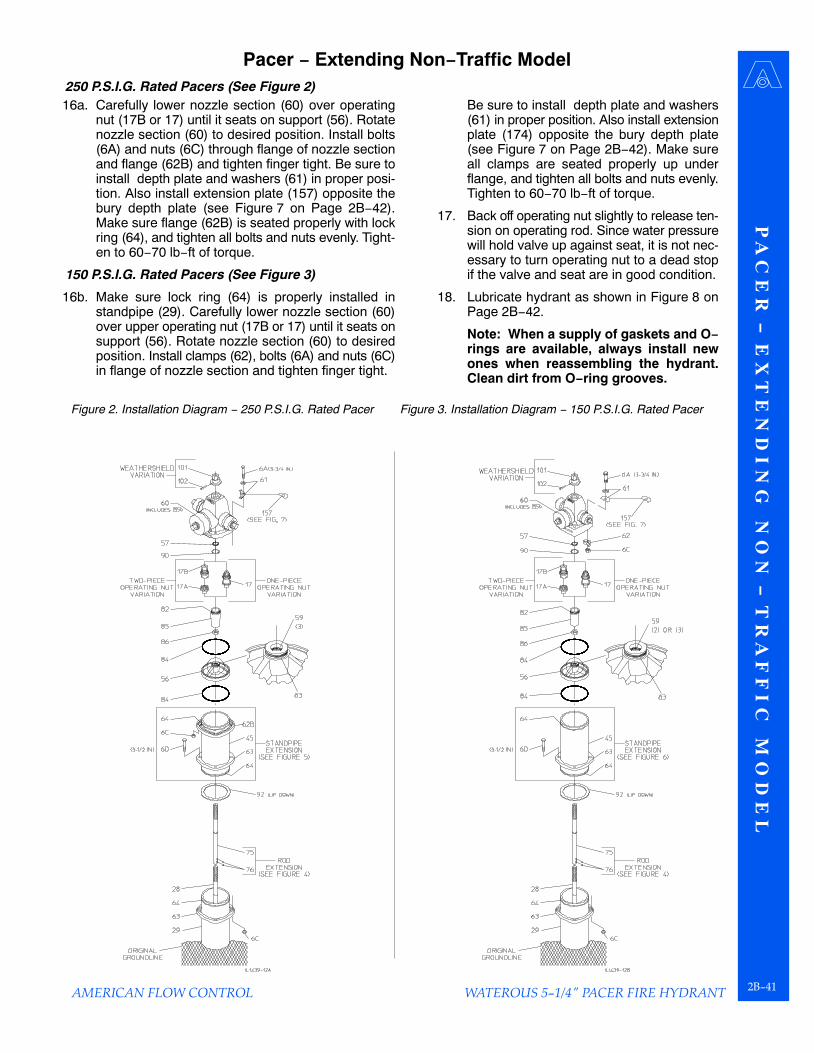
P A
C E
R − E
X T
E N
D I N
G N
O N
− T R
A F
F I C
M O
D E
L
WATEROUS 5−1/4" PACER FIRE HYDRANT2B−41
AMERICAN FLOW CONTROL
Pacer − Extending Non−Traffic Model250 P.S.I.G. Rated Pacers (See Figure 2)
16a. Carefully lower nozzle section (60) over operatingnut (17B or 17) until it seats on support (56). Rotatenozzle section (60) to desired position. Install bolts(6A) and nuts (6C) through flange of nozzle sectionand flange (62B) and tighten finger tight. Be sure toinstall depth plate and washers (61) in proper posi-tion. Also install extension plate (157) opposite thebury depth plate (see Figure 7 on Page 2B−42).Make sure flange (62B) is seated properly with lockring (64), and tighten all bolts and nuts evenly. Tight-en to 60−70 lb−ft of torque.
150 P.S.I.G. Rated Pacers (See Figure 3)
16b. Make sure lock ring (64) is properly installed instandpipe (29). Carefully lower nozzle section (60)over upper operating nut (17B or 17) until it seats onsupport (56). Rotate nozzle section (60) to desiredposition. Install clamps (62), bolts (6A) and nuts (6C)in flange of nozzle section and tighten finger tight.
Be sure to install depth plate and washers(61) in proper position. Also install extensionplate (174) opposite the bury depth plate(see Figure 7 on Page 2B−42). Make sureall clamps are seated properly up underflange, and tighten all bolts and nuts evenly.Tighten to 60−70 lb−ft of torque.
17. Back off operating nut slightly to release ten-sion on operating rod. Since water pressurewill hold valve up against seat, it is not nec-essary to turn operating nut to a dead stopif the valve and seat are in good condition.
18. Lubricate hydrant as shown in Figure 8 onPage 2B−42.
Note: When a supply of gaskets and O−rings are available, always install newones when reassembling the hydrant.Clean dirt from O−ring grooves.
Figure 2. Installation Diagram − 250 P.S.I.G. Rated Pacer Figure 3. Installation Diagram − 150 P.S.I.G. Rated Pacer

P A
C E
R −
E X
T E
N D
I N
G
N O
N −
T R
A F
F I
C
M O
D E
L
WATEROUS 5−1/4" PACER FIRE HYDRANT2B−42 AMERICAN FLOW CONTROL
Pacer − Extending Non−Traffic Model
Figure 4. Rod Extension Installation Figure 5. Standpipe / Flange Orientation (250 P.S.I.G.)
Figure 6. Standpipe / Flange Orientation (150 P.S.I.G.) Figure 7. Extension Plate Installation
Figure 8. Lubrication Details
Oil Reservoir Hydrants: Remove oil level plug. Add oilto the level of the plug. Use white mineral oil USP Mo-bil Whiterex 425 or equal.
Non−Oil Reservoir Hydrants: Remove screw from op-erating nut and add approximately one tablespoon ofoil through opening. Replace screw. Use white mineraloil USP Mobil Whiterex 425 or equal.
Remove all nozzle caps, clean rust or corrosion fromthreads of nozzles and caps. Replace cap gaskets ifnecessary. Apply a light coat of grease to nozzlethreads before replacing cap. Use Mystik� FG−2 FoodMachinery Grease.
1.
2.