index terms ijser · pdf file · 2016-09-09the following are the compression...
TRANSCRIPT

International Journal of Scientific & Engineering Research, Volume 7, Issue 3, March-2016 331 ISSN 2229-5518
IJSER © 2016 http://www.ijser.org
Binary Image Compression Algorithms for FPGA Implementation
Fahad Lateef, Najeem Lawal, Muhammad Imran
Abstract — In this paper, we presents results concerning binary image compression algorithms for FPGA implementation. Digital images are found in many places and in many application areas and they display a great deal of variety including remote sensing, computer sciences, telecommunication systems, machine vision systems, medical sciences, astronomy, internet browsing and so on. The major obstacle for many of these applications is the extensive amount of data required representing images and also the transmission cost for these digital images. Several image compression algorithms have been developed that perform compression in different ways depending on the purpose of the application. Some compression algorithms are lossless (having same information as original image), and some are lossy (loss information when compressed). Some of the image compression algorithms are designed for particular kinds of images and will thus not be as satisfactory for other kinds of images. In this project, a study and investigation has been conducted regarding how different image compression algorithms work on different set of images (especially binary images). Comparisons were made and they were rated on the bases of compression time, compression ratio and compression rate. The FPGA workflow of the best chosen compression standard has also been presented. These results should assist in choosing the proper compression technique using binary images.
Index Terms—Binary Image Compression, CCITT, FPGA, JBIG2, Lempel-Ziv-Welch, PackBits, TIFF, Zip-Deflate.
—————————— ——————————
1 INTRODUCTION OMPUTER usage for a variety of tasks has increased im-mensely during the last two decades. The arrival of the digital camera caused there to be the need for greater use
of storage, manipulation and the transmission of digital imag-es. A plurality of compression algorithms of images have been developed to carry out the compression in different ways de-pending on the purpose of application. In some image com-pression algorithms, it is possible to change the parameters used in order to adjust the compression in relation to the im-age. Some of the image compression algorithms are designed for particular types of images and will thus be unsatisfactory for other kinds of images. In image compression, choosing the proper compression technique can make a significant difference to the appearance (Quality), size and transfer of an image file. People often fail to interpret or understand correctly the image compression topic, because there is a real lack of understanding with regards to the capabilities of the different types of compression algo-rithm. It is necessary to understand which type of compres-sion to use for different types of images, otherwise the final result may be a poor image quality or that the image file sizes that are significantly larger than necessary. The aim of this project was to make a comparison of some of
the most used image compression algorithms on a set of bina-ry images on the bases of compression time, compression ratio and compression rate. The majority of the compression algo-rithms which had been tested are TIFF compression algo-rithms. Different types of images have been tested on different compression algorithms. Images with different formats, char-acteristics, photometric interpretation, different physical di-mensions, size, no. of objects, thus a series of images have been used. It has been noted how well different compression algorithms work for different types of images and that some algorithms perform better than others depending on the ap-plication and type of image being working with.
2 RELETED WORK There are many image compression algorithms which have been researched in bi-level image encoding domain. There are two types of image compression: lossless image compression and lossy image compression [1]. The majority of the binary image compression algorithms are lossless. Examples of these include, Run Length Encoding [2] and Arithmetic Coding [3], [4]. RLE includes ITU-T Fax Group 3 (G3-1D, G3-2D) encod-ing, Group 4 (G4) encoding [5], [6], [7], [31], [32] using Huff-man [8], rectangular partition encoding [9] and so on. The ISO/IEC JBIG and JBIG2 [3] [26] standards for lossless bi-level image compression use arithmetic coding. Lossy image com-pression algorithms, such as JPEG (Joint Photographic Experts Group) encoding [10], [11]. JPEG compression algorithms are normally used for color images compression, but are not as good in relation to pure binary image compressions. Paper [12] presents an algorithm for lossless binary image compres-sion based on Block Arithmetic coder (BAC). In paper [13], a lossless bi-level image compression scheme is proposed that can achieve a high compression ratio using rectangular parti-
C
———————————————— • Fahad Lateef is currently working as a Lecturer in University of Loralai,
Pakistan, PH-+923353642298. E-mail: [email protected] • Najeem Lawal - Department of Electronics Engineering (EKS) Mid Sweden
University, Sweden, PH: +46(010-1428561). E-mail: [email protected]
• Muhammad Imran - Department of Electronics Engineering (EKS) Mid Sweden University, Sweden, PH: +46(010-1428416). E-mail: [email protected]
IJSER
International Journal of Scientific & Engineering Research, Volume 7, Issue 3, March-2016 332 ISSN 2229-5518
IJSER © 2016 http://www.ijser.org
tioning of the black region (1’s) of the input image. Paper [14] proposes two lossless compression algorithms using the same rectangle partitioning, but this involves 2D Run Length cod-ing. Rectangle partitioning of a binary image into overlapping and non-overlapping rectangles can be studied in [15]. In pa-per [16], the new standard JBIG2 for lossless and lossy com-pression of bi-level images is presented. Paper [17] presents two efficient methods to improve the resolution scalability for bi-level images using JPEG2000. In paper [18], a binary image compression scheme is proposed, based on chain coding tech-niques and entropy coders.
3 BINARY IMAGE COMPRESSION Binary images are used widely in daily life, especially for OA (Office Automation), document process, line drawings, letters, facsimiles, maps…etc. Although color documents are often seen, there is still a rapid increase in the use of binary images. The storage and transmission of binary images becomes ever more important when these images are required to be pre-served and transmitted. The stored binary images may have large space requirements and in order to reduce the storage space and transmission time, efficient coding technologies have been proposed. Many image compression algorithms have been researched in binary image encoding domain in [19].
4 IMAGE COMPRESSION ALGORITHM The following are the compression algorithms used in this project.
• PackBits • Lempel-Ziv-Welch (LZW) • Zip(Deflate) • JBIG2 • CCITT Fax 3 & 4
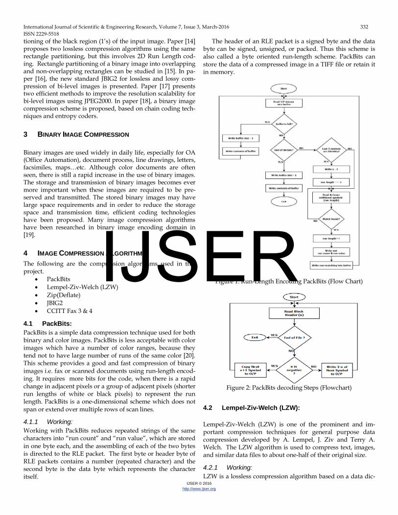
4.1 PackBits: PackBits is a simple data compression technique used for both binary and color images. PackBits is less acceptable with color images which have a number of color ranges, because they tend not to have large number of runs of the same color [20]. This scheme provides a good and fast compression of binary images i.e. fax or scanned documents using run-length encod-ing. It requires more bits for the code, when there is a rapid change in adjacent pixels or a group of adjacent pixels (shorter run lengths of white or black pixels) to represent the run length. PackBits is a one-dimensional scheme which does not span or extend over multiple rows of scan lines.
4.1.1 Working: Working with PackBits reduces repeated strings of the same characters into “run count” and “run value”, which are stored in one byte each, and the assembling of each of the two bytes is directed to the RLE packet. The first byte or header byte of RLE packets contains a number (repeated character) and the second byte is the data byte which represents the character itself.
The header of an RLE packet is a signed byte and the data byte can be signed, unsigned, or packed. Thus this scheme is also called a byte oriented run-length scheme. PackBits can store the data of a compressed image in a TIFF file or retain it in memory.
Figure 1: Run-Length Encoding PackBits (Flow Chart)
Figure 2: PackBits decoding Steps (Flowchart)
4.2 Lempel-Ziv-Welch (LZW): Lempel-Ziv-Welch (LZW) is one of the prominent and im-portant compression techniques for general purpose data compression developed by A. Lempel, J. Ziv and Terry A. Welch. The LZW algorithm is used to compress text, images, and similar data files to about one-half of their original size.
4.2.1 Working: LZW is a lossless compression algorithm based on a data dic-
IJSER

International Journal of Scientific & Engineering Research, Volume 7, Issue 3, March-2016 333 ISSN 2229-5518
IJSER © 2016 http://www.ijser.org
tionary (translation table or string table). It reads the string of input characters, maps into the code and adds to a table of strings. The length of the output code can be any length, hav-ing more bits than a single character e.g. Using 8-bit character, the first 256 codes are assigned to a standard character set and the remainder are assigned to strings.
Figure 3: Lempel-Ziv-Welch (Flow Chart) [21]
4.3 Zip (deflate encoding): Zip allows many compression methods such as shrunk, Im-ploded, Deflate or Deflate64. In this project the zip-deflate (combination of LZ77 and Huffman encoding) algorithm was used. A zip encoding technique is used in many compression programs such as WinZip, pkzip, gzip etc. Zip is a highly ef-fective compression algorithm in terms of efficiency and speed. It is also a dictionary based algorithm used to encode a recurring sequence. Zip supports most data formats, including text and images because it treats the input data as a generic stream of bytes.
4.3.1 Working: Zip algorithms work by replacing the repeated occurrences of data with references to a single copy of that data existing pre-viously in the input (uncompressed) data stream.
4.4 LZ77: LZ77 is a dictionary based encoding algorithm which replaces a string of symbols with a reference to a dictionary location for the same string. The dictionary does not contain a list of all known symbols; it contains the last “N” symbols encod-ed/decoded.
Figure 4: Flow chart Encoder (LZ77). If there is a large N, then it will take longer to search for a match in the dictionary and will require more bits to store the offset into the dictionary. The amount of symbols in the dic-tionary is represented by a whole power of 2. After the process and addition of the (N + 1) symbol to the dictionary, the first symbol is removed and an equal number of the oldest symbols are caused to slide out by additional symbols.
Figure 5: Flow chart Decoder (LZ77).
IJSER
International Journal of Scientific & Engineering Research, Volume 7, Issue 3, March-2016 334 ISSN 2229-5518
IJSER © 2016 http://www.ijser.org
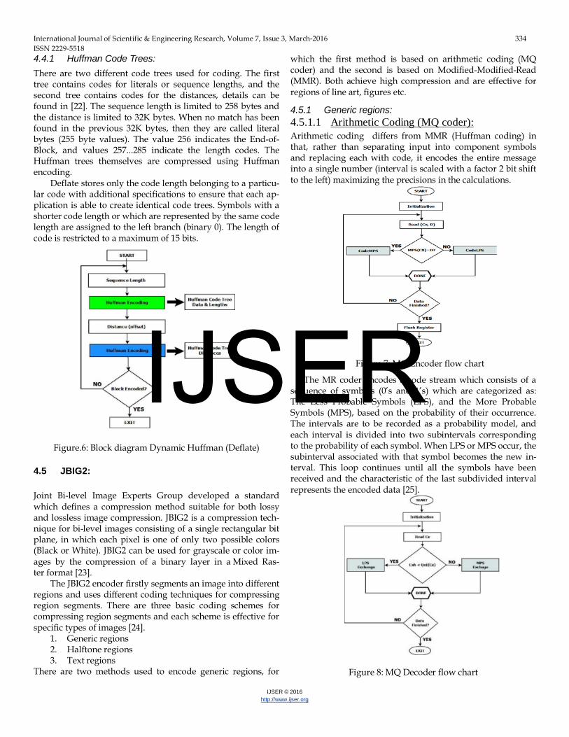
4.4.1 Huffman Code Trees:
There are two different code trees used for coding. The first tree contains codes for literals or sequence lengths, and the second tree contains codes for the distances, details can be found in [22]. The sequence length is limited to 258 bytes and the distance is limited to 32K bytes. When no match has been found in the previous 32K bytes, then they are called literal bytes (255 byte values). The value 256 indicates the End-of-Block, and values 257...285 indicate the length codes. The Huffman trees themselves are compressed using Huffman encoding.
Deflate stores only the code length belonging to a particu-lar code with additional specifications to ensure that each ap-plication is able to create identical code trees. Symbols with a shorter code length or which are represented by the same code length are assigned to the left branch (binary 0). The length of code is restricted to a maximum of 15 bits.
Figure.6: Block diagram Dynamic Huffman (Deflate)
4.5 JBIG2:
Joint Bi-level Image Experts Group developed a standard which defines a compression method suitable for both lossy and lossless image compression. JBIG2 is a compression tech-nique for bi-level images consisting of a single rectangular bit plane, in which each pixel is one of only two possible colors (Black or White). JBIG2 can be used for grayscale or color im-ages by the compression of a binary layer in a Mixed Ras-ter format [23].
The JBIG2 encoder firstly segments an image into different regions and uses different coding techniques for compressing region segments. There are three basic coding schemes for compressing region segments and each scheme is effective for specific types of images [24].
1. Generic regions 2. Halftone regions 3. Text regions
There are two methods used to encode generic regions, for
which the first method is based on arithmetic coding (MQ coder) and the second is based on Modified-Modified-Read (MMR). Both achieve high compression and are effective for regions of line art, figures etc.
4.5.1 Generic regions: 4.5.1.1 Arithmetic Coding (MQ coder):
Arithmetic coding differs from MMR (Huffman coding) in that, rather than separating input into component symbols and replacing each with code, it encodes the entire message into a single number (interval is scaled with a factor 2 bit shift to the left) maximizing the precisions in the calculations.
Figure 7: MQ Encoder flow chart
The MR coder encodes a code stream which consists of a sequence of symbols (0’s and 1’s) which are categorized as: The Less Probable Symbols (LPS), and the More Probable Symbols (MPS), based on the probability of their occurrence. The intervals are to be recorded as a probability model, and each interval is divided into two subintervals corresponding to the probability of each symbol. When LPS or MPS occur, the subinterval associated with that symbol becomes the new in-terval. This loop continues until all the symbols have been received and the characteristic of the last subdivided interval represents the encoded data [25].
Figure 8: MQ Decoder flow chart
IJSER

International Journal of Scientific & Engineering Research, Volume 7, Issue 3, March-2016 335 ISSN 2229-5518
IJSER © 2016 http://www.ijser.org
An estimation of the probability on the LPS and the MPS renormalization path is conducted in the probability estima-tion block. The renormalization block generates compressed bits. The compressed data out block contains the compressed data and, finally, the FLUSH block is used to terminate the encoding operations and it generates the required terminating marker. Details can be found in [26].
There are two disadvantages in relation to arithmetic cod-ing, one being that high precision arithmetic is required to shrink the current interval and the second is that no output is produced until the entire file has been read [27].
4.5.2 Text regions:
There are two methods used to encode text regions or symbol regions. In relation to compression based on symbols that can be non-text or any alphabet, these symbols are stored in dic-tionaries and are encoded as generic regions. The first method to encode the symbol regions is Pattern Matching and Substi-tution (PM&S) and the second method is Soft Pattern Match-ing (SPM) Details can be found in [28].
4.5.3 Halftone regions:
There are two methods used to encode halftone regions, the first method involves context-based arithmetic coding used in JBIG1 [29]. The second method is to reverse the half tone pro-cess (converting it back to gray scale) [30]. High levels of compression can be achieved by halftone regions, but apart from in special circumstances, they are lossy.
4.6 CCITT Group 3:
The CCITT is derived from French: (Comité Consultatif Inter-national Téléphonique et Télégraphique). It was developed in 1985 by the International Telegraph and Telephone Consulta-tive Committee. The main application of Group 3 is in relation to bi-level im-ages, fax transmission and is also effective for scanned images and handwritten documents. Group 3 are represented by two types
• One Dimensional G3 • Two Dimensional G3
4.6.1 One Dimensional coding scheme:
In the G3 one dimensional coding scheme, the line data is made up of a series of variable length code words in which each code word represents a run-length of black runs and white runs. If the data line begins with black runs, it will send a white run-length of zero. Tables in [31] show all the code words for white run-lengths and black run-lengths. There are two types of code words, one which terminates a code word (range of 0 to 63 pels) and other is a make-up code word (range of 64 to 1728 pels).
4.6.2 Two-Dimensional coding scheme:
Figure 9: Flow diagram Group 3 Two-Dimensional Coding. The two-dimensional coding scheme is an extension of the one-dimensional coding scheme. A method used in the two-dimensional coding scheme is called line-by-line coding. Cod-ing procedure of CCITT Group 3 can be found in [31].
4.7 CCITT G4:
Group 4 is an extended version of Group 3 2D, developed by the International Telegraph and Telephone Consultative Committee. The only difference between Group 4 and Group 3 2D is the parameter K or K factor. Group 4 uses an imaginary line which serves as the reference line (scan line of white pix-els).
The Group 4 algorithm is more efficient than the Group 3 2D and has replaced the use of Group 3 2D in many applica-tions. The encoding speed of G4 is faster than that of the G32D algorithm and G4 does not require any EOL [32].
IJSER
International Journal of Scientific & Engineering Research, Volume 7, Issue 3, March-2016 336 ISSN 2229-5518
IJSER © 2016 http://www.ijser.org
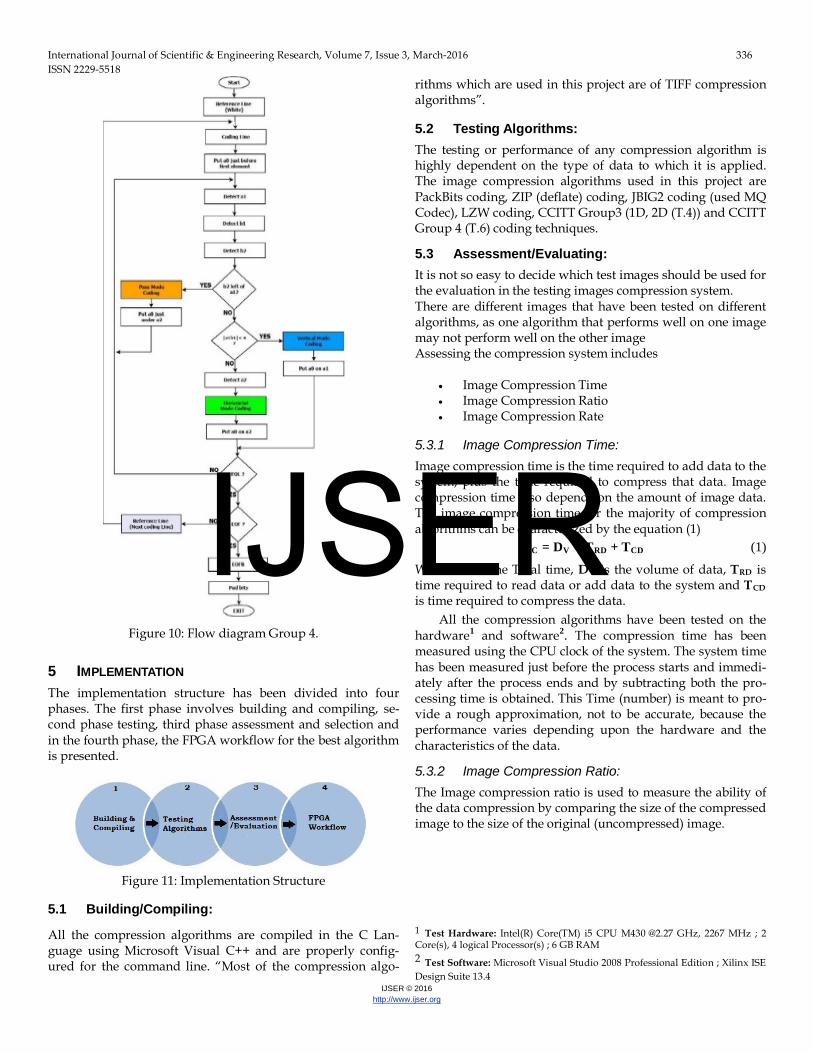
Figure 10: Flow diagram Group 4.
5 IMPLEMENTATION The implementation structure has been divided into four phases. The first phase involves building and compiling, se-cond phase testing, third phase assessment and selection and in the fourth phase, the FPGA workflow for the best algorithm is presented.
Figure 11: Implementation Structure
5.1 Building/Compiling:
All the compression algorithms are compiled in the C Lan-guage using Microsoft Visual C++ and are properly config-ured for the command line. “Most of the compression algo-
rithms which are used in this project are of TIFF compression algorithms”.
5.2 Testing Algorithms:
The testing or performance of any compression algorithm is highly dependent on the type of data to which it is applied. The image compression algorithms used in this project are PackBits coding, ZIP (deflate) coding, JBIG2 coding (used MQ Codec), LZW coding, CCITT Group3 (1D, 2D (T.4)) and CCITT Group 4 (T.6) coding techniques.
5.3 Assessment/Evaluating:
It is not so easy to decide which test images should be used for the evaluation in the testing images compression system. There are different images that have been tested on different algorithms, as one algorithm that performs well on one image may not perform well on the other image Assessing the compression system includes
• Image Compression Time • Image Compression Ratio • Image Compression Rate
5.3.1 Image Compression Time:
Image compression time is the time required to add data to the system, plus the time required to compress that data. Image compression time also depends on the amount of image data. The image compression time for the majority of compression algorithms can be characterized by the equation (1)
TC = DV × TRD + TCD (1)
Where TC is the Total time, DV is the volume of data, TRD is time required to read data or add data to the system and TCD is time required to compress the data.
All the compression algorithms have been tested on the hardware1 and software2. The compression time has been measured using the CPU clock of the system. The system time has been measured just before the process starts and immedi-ately after the process ends and by subtracting both the pro-cessing time is obtained. This Time (number) is meant to pro-vide a rough approximation, not to be accurate, because the performance varies depending upon the hardware and the characteristics of the data.
5.3.2 Image Compression Ratio:
The Image compression ratio is used to measure the ability of the data compression by comparing the size of the compressed image to the size of the original (uncompressed) image.
1 Test Hardware: Intel(R) Core(TM) i5 CPU M430 @2.27 GHz, 2267 MHz ; 2 Core(s), 4 logical Processor(s) ; 6 GB RAM 2 Test Software: Microsoft Visual Studio 2008 Professional Edition ; Xilinx ISE Design Suite 13.4
IJSER
International Journal of Scientific & Engineering Research, Volume 7, Issue 3, March-2016 337 ISSN 2229-5518
IJSER © 2016 http://www.ijser.org
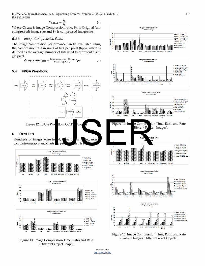
𝑪𝑹𝑨𝑻𝑰𝑶 = 𝑺𝑶𝑺𝑪
(2) Where CRATIO is image Compression ratio, SO is Original (un-compressed) image size and SC is compressed image size.
5.3.3 Image Compression Rate:
The image compression performance can be evaluated using the compression rate in units of bits per pixel (bpp), which is defined as the average number of bits used to represent a sin-gle pixel.
𝑪𝑪𝑪𝑪𝑪𝑪𝑪𝑪𝑪𝑪𝑪𝑹𝑨𝑻𝑬 = 𝑪𝑪𝑪𝑪𝑪𝑪𝑪𝑪𝑪𝒅 𝑰𝑪𝒂𝒈𝑪 𝑺𝑪𝒛𝑪𝑩𝑪𝒕𝑪𝑵𝒖𝑪𝒃𝑪𝑪 𝑪𝒇 𝑷𝑪𝒙𝑪𝒍𝑪
𝒃𝑪𝑪 (3)
5.4 FPGA Workflow:
Figure 12: FPGA Workflow CCITT Group 4
6 RESULTS Hundreds of images were tested, some of the testing results, comparison graphs and charts are presented in this section.
Figure 13: Image Compression Time, Ratio and Rate
(Different Object Shape).
Figure 14: Image Compression Time, Ratio and Rate (Different Pattern Images).
Figure 15: Image Compression Time, Ratio and Rate (Particle Images, Different no of Objects).
IJSER

International Journal of Scientific & Engineering Research, Volume 7, Issue 3, March-2016 338 ISSN 2229-5518
IJSER © 2016 http://www.ijser.org
Figure 16: Image Compression Time, Ratio and Rate (Different Image Size, Same Object Size).
7 CONCLUSION / FUTURE WORK Compression scheme depends greatly on the type of data to which it is applied. A scheme that works well on one data set may do poorly on the next. The comparison results show which compression algorithm has the ability to compress im-ages of any size to a significantly reduced size than that of the original size. However the time taken by each image to com-press is an approximation of the CPU time taken by the sys-tem for each algorithm. This CPU time is the smallest possible that these algorithm can take. This time (number) is meant to provide a rough approximation, not to be accurate, because the performance varies depending upon the hardware and the characteristics of the data. Different compression algorithms have been studied, compared and rated in terms of compres-sion time and compression ratio. The comparison with vari-ous forms of image compression techniques suggests that, in the majority of cases, the CCITT G4 compression standard has the best compressed size with an efficient time taken by this compression process. The CCITT G4 has been compared to various generalized algorithms that are being used for differ-ent types of images. They were also compared to other CCITT group algorithms i.e. Group 3 one dimensional and two di-mensional. The result suggests that CCITT G4 is more reliable in terms of compression time and compression ratio. However the complexity can be traded when the CCITT Group 4 algo-rithms are implemented on hardware. An FPGA workflow is proposed for CCITT G4 compression standard.
Nowadays, these algorithms are very popular with the sensor based smart camera. These smart cameras usually work in a network with a wireless node or are connected in some remote location by means of a smaller data rate line. Hence, the com-
pression ratios of these algorithms makes them a popular choice and have re-used a technology that has been side-lined by so many newer and better algorithms that focus on more improved color images. This study provides a basis for the implementation of these algorithms on any flexible hardware platform such as FPGA, micro controllers etc. which will pro-vide a faster compression of images received through any me-dium such as cameras and scanners.
8 ACKNOWLEDGMENT I would like to express my deepest regards and gratitude to my supervisor Dr. Najeem Lawal, Dr Muhammad Imran, Dr Abdul Waheed Malik, Dr Khursheed and Mr Aart Mulder for their guidance, support and encouragement throughout this work. Without their constant guidance and support this work would not have been possible. I would also like to express my gratitude to Mid Sweden Uni-versity (MIUN) for their support.
9 REFERENCES [1] A. K. Jain, "Fundamentals of Digital Image Processing". Prentice Hall, 1995. [2] Run length encoding -
dia, http://en.wikipedia.org/wiki/Runlength_encoding [3] ITU Recommendation T.82,”Progressive bi-level image compression”. JBIG.
1993 [4] Witten I. H, Neal R. M. & Cleary J. G. “Arithmetic coding for data compres-
sion”.1987 [5] ITU-T official site, http://www.itu.int/ [6] T.4 Fax Modem Protocol - RAO
search, http://www.gaoresearch.com/products/faxsoftware/other/t4.php [7] Group 3 Facsimile
tion, http://www.garretwilson.com/essays/computers/group3fax.html [8] David Salomon. “A Cosine Introduction to Data Compression” Chapter 2.
Springer, 2008 [9] Sherif A. Muhammad & Mustafa M. Fahmy, “Binary Image Compression
Using Efficient Partitioning into Rectangular Regions”. IEEE Trans. On Comm., Vol. 43, No. 5, pp. 1888-1893, May 1995
[10] Syed Ali Khayam, “The Discrete Cosine Transform: Theory and Application” ECE 802 – 602: Information Theory and Coding, Michigan State University, March. 2003.
[11] ITU-T. ISO DIS 10918-1 Digital compression and coding of continuous-tone still images (JPEG). Recommendation T.81.
[12] Maire D. Reavy and Charles G. Boncelet,” An Algorithm for Compression of Bi-level Images”, IEEE transactions on image processing, vol. 10, no. 5, May 2001
[13] S. Zahir and M. Naqvi, "A New Rectangular Partitioning Based Lossless Binary Image Compression Scheme". IEEE CCECE/CCGEI, pp.281- 285, May 2005.
[14] M. Kafashan, H.Hosseini, S.Beygiharchegani, P.Pad and F.Marvasti, “New Rectangular Partitioning Methods for Lossless Binary Image Compression”, ICSP. 2010
[15] A. Quddus & Moustafa M. Fahmy, “Binary text image compression using overlapping rectangular partitioning,” Pattern Recognition Letters, Vol 20, Is-sue 1, 1999
[16] Fumitaka Ono, William Rucklide, Ronald Arps & Cornel Constantinescu, “JBIG2 - The ultimate bi-level image coding standard”, IEEE. 2000
[17] Rahul Raguram, Michael W. Marcellin, and Ali Bilgin, “Improved resolution scalability for bi-level image data in JPEG2000”, Data Compression Confer-
IJSER
International Journal of Scientific & Engineering Research, Volume 7, Issue 3, March-2016 339 ISSN 2229-5518
IJSER © 2016 http://www.ijser.org
ence. 2007 [18] Saif Zahir & Mehmood Naqvi, “A near Minimum Sparse Pattern Coding
Based Scheme for Binary Image Compression”, IEEE. 2005 [19] Hao Sung and Wen-Yan Kuo “A Skip-line with Threshold Algorithm for
Binary Image Compression, IEEE Trans. 3rd International Congress on Image and Signal Processing (CISP2010). 2010.
[20] http://help.accusoft.com/ImageGear-Silverlight/v17.3/Windows/HTML/Packbits_Compression.html
[21] Steven W. Smith, “The Scientist and Engineer's Guide to Digital Signal Processing”, 1997
[22] ftp://ds.internic.net/rfc/rfc1951.txt [23] ITU Recommendation T.44,” Mixed Raster Content (MRC)”. JBIG. JAN 2005 [24] D. Tompkins and F. Kossentini. A Fast Segmentation Algorithm for Bi-level
Image Compression Using JBIG2. Proc of the 1999 IEEE International Confer-ence on Image Processing (ICIP), pp. 224–228, Kobe, Japan, Oct. 1999
[25] Taoufik Saidani, Mohamed Atri, Rached Tourki, “Implementation of JPEG 2000 MQ-Coder”, IEEE, International Conference on Design & Technology of Integrated Systems in Nano scale Era. 2008
[26] ITU-T Recommendation T.88, “Information technology Lossy/lossless coding of bi-level images”. Feb. 2000
[27] Krishna Bharath Kolluru, 2009. "Optimization of Arithmetic and MQ coding", ECE 734 VLSI Array Structures for Digital Signal Processing.
[28] Paul G. Howard, Faouzi Kossentini, Member, Bo Martins, Søren Forchham-mer, and William J. Rucklidge, “The Emerging JBIG2 Standard”, IEEE trans-actions on circuits and systems for video technology, vol. 8, no. 7, Nov 1998
[29] S. Forchhammer and K. S. Jensen, “Data compression of scanned halftones images,” IEEE Trans. Commun., vol. 42, pp. 1881–1893, Feb.–Apr. 1994
[30] S. Forchhammer and K. S. Jensen, “Data compression of scanned halftones images,” IEEE Trans. Commun., vol. 42, pp. 1881–1893, Feb.–Apr. 1994.
[31] ITU-T Recommendation T.4, “Standardization of Group 3 facsimile terminals for document transmission”. July 2003
[32] ITU-T recommendation t.6, “facsimile coding schemes and coding Control functions for Group 4 Facsimile”. 1984 IJSER