index page - hydro craft · • installation is a snap - clamp, fitting, and cushion are all in one...
TRANSCRIPT

HYDRO-CRAFT • FOR ORDERS CALL 702-566-8798 (WEST COAST) OR 248-652-8100 (EAST COAST)
Multi-Clamp System 3
Cutaway 4Planning 5Mounting Methods 6-7Junction Adapters 8Multi-Clamp Bulkhead Spacer 8Junction Adapters 9Clamping Unit 10Clamping Unit with Outside Holes 10Single Clamping Unit 11Double Clamping Unit 11Split Bushings for Tube & Pipe 11Split Bushings for Hose 12Mounting Adapters 13
Index Page
Introduction 2
®
1
• A rail mounted clamp with Multi-Clamp'sability to clamp the line at the fitting
• Installation is a snap - clamp, fitting, andcushion are all in one package
Strut-Adapter 15
• Perfect for Mobile, Pneumatic,Hydraulic, Electrical, HVAC, Fuel Line
• Line sizes from 1/8" through 8"• Interchangeable with other brands
Hydro-Clamp 19
• High-quality Styrene Butadiene Rubber• Easy mounting using pipe straps• Line sizes from 1/4" tube or pipe to
1-1/2" pipe or 2-1/8" tube
Econo-Isolator 20
• Easy channel mounting installation• Line sizes from 1/4" to 2" tube• High-quality materials of construction• Greatly reduces line noise
Silent-Strut 18
• Reduces line noise by as much as 80%• Line sizes from 1/4" to 2" pipe• Easy channel mounting installation• High-quality materials of construction
Hydro-Strut 14
• Vibration and shock-free rail mounting• Easily snap hose or tubing into elastomer
cushion• Space saving design
Walker-Strut 16-17
DISCONTINUED

HYDRO-CRAFT • FOR ORDERS CALL 702-566-8798 (WEST COAST) OR 248-652-8100 (EAST COAST)2
MULTI-CLAMP APPLICATIONS
HC-CC/01ACopyright 2006 Hydro-Craft Inc.
Strut-Adapter®, Hydro-Strut®, Silent-Strut®, andWalker-Strut®, are registered trademarks.
Multi-Clamp® System -U.S. Patent No. 3,397,431 & 3,414,220Weld Adapter® -U.S. Patent No. 5,016,461Strut-Adapter® -U.S. Patent No. 4,934,635 & 4,997,148
ressures, and fewervibrating components may help prevent leaks; however,this is not the complete answer.
One of the most crucial requirements is to clamp thehydraulic lines and properly secur releaks can occur. Unclamped hydraulic tubing will rever-berate as does a tuning fork. Fluid velocity, pressure, andimproper line size all contribute to high frequency vibra-tion, shock, surge, and noise. Far more damaging is theraround couplings, r
Now in our 59th year, Hydro-Craft is proud to present this catalog of seven separate and unique clamping systems.
years ago, Hydro-Craft engineered and patented a system for50
clamping hydraulic lines and securing breakpoint This system is called the MULTI-CLAMP® and is the industry standard in clamped breakpoint systems.
Now, Hydro-Craft applies its expertise to include a fullrange of clamping systems, including the WALKER-STRUT ®
channel-mounted system, the only clamp in the worldwith this exclusive breakpoint feature. Also available arethe HYDRO-STRUT ® , SILENT-STRUT®, Econo-Isolator, andHydro-Clamp channel mounting systems.
All systems are available in steel or 304 stainless steel.MULTI-CLAMP is also available in aluminum.
®

HYDRO-CRAFT • FOR ORDERS CALL 702-566-8798 (WEST COAST) OR 248-652-8100 (EAST COAST)
*From Fluid Power Handbook
RECOMMENDED SUPPORT CLAMP SPACING*
3
The MULTI-CLAMP SYSTEM enables you to route singleline runs, multiple runs of the same line diameters, ormultiple runs of various diameters. Multiple line runscan be stacked to conserve space and make installa-tions more rigid. Center line dimensions between alllines remain the same, both horizontal and vertical,when MULTI-CLAMPS are stacked. Mount an addi-tional CLAMPING UNIT upon the existing MULTI-CLAMPand attach it by threading a thread adapter into thestacking nut. MULTI-CLAMPS are progressively built upthis way with the last being secured by a standard boltthreaded into the STACKING NUT.
The MULTI-CLAMP SYSTEM provides definite referencefor measuring . . . so important in laying out line runs.Quite an advantage over clamping devices thatchange center distance both vertically and horizontallywith each change in line diameter. This advantagecan be fully realized when stacking line runs, becausewith MULTI-CLAMP, both vertical and horizontal centerline distances remain specifically designed to give youexact spacing and ease of installation.
MULTI-CLAMP is available in steel, stainless steel andaluminum. The standard bushing material is StyreneButadiene.
Using the following charts, determine the series ofMULTI-CLAMP required and the number of clampsrequired. Then refer to the dimensional data andmounting instructions on the following pages.
®
LINE SIZE MULTI-CLAMP SERIES
3/16- THRU 3/4-INCH O.D. HC-101/4- THRU 1-INCH O.D. HC-163/8- THRU 2-INCH O.D. HC-32
1- THRU 2-1/2-INCH I.D. HC-462- THRU 4-INCH I.D. HC-725- THRU 6-INCH I.D. HC-96
TUBE O.D. APPROX. SPACEBETWEEN SUPPORTS
1/4-, 5/16-, 3/8-, 1/2- INCH 3-FEET5/8-, 3/4-, 7/8-INCH 4-FEET1-INCH 5-FEET1-1/4-, 1-1/2-INCH 7-FEET2-INCH & UP 7- TO 10-FEET
The Multi-Clamp® System

HYDRO-CRAFT • FOR ORDERS CALL 702-566-8798 (WEST COAST) OR 248-652-8100 (EAST COAST)4
®
A Socket-head stacking nut, is used in combination with either
B a thread adapter,
C a self-tapping adapter, or
D a weld adapter, to secure the lower Clamping Unit directly to a mounting surface. The Stacking Nut is also used in combination with
E a thread adapter, lockwasher, and standard nut to attach the lower Clamping Unit through a drilled hole in mounting to a plate of 3/8 inch (or less) thickness.After inserting Junction Adapters or Split Bushings and Lines into the lower Clamping Unit, the upper Clamping Unit is attached by positioning it over the Lower Clamping Unit and placing
F a standard bolt and lockwasher, through each mounting hole and threading the bolt securely into its corresponding Stacking Nut. This completes the assembly of a basic MULTI-CLAMP. In bridge mounting between two columns, or when a MULTI-CLAMP is suspended from a column, either the
E thread adapter, lockwasher, and standard nut, combination or
G a standard bolt and lockwasher, can be used to secure the Stacking Nut to the lower Clamping Unit.
H Mounting adapters are placed into appropriate holes, the lines or Junction Adapters installed, the upper Clamping Unit attached, and the complete assembly then secured by the Mounting Adapters and standard bolts.
I Split bushings are placed into appropriate holes, available with or without ridge.
A
C
D
F
E
I
I
G
H
B
Multi-Clamp® Exploded View

HYDRO-CRAFT • FOR ORDERS CALL 702-566-8798 (WEST COAST) OR 248-652-8100 (EAST COAST)
NOTE: If a large number of lines are to be run,the following procedure is recommended:Cut lower CLAMPING UNIT in lengths for totalnumber of lines to be installed. Next, cutupper CLAMPING UNIT in lengths for 2 linesonly. Installation is then completed by securingonly two lines at a time as the run progresses.
5
PLANNING GUIDE
THE MULTI-CLAMP® SYSTEM PROVIDES FOR VISUALPLANNING OF LINE INSTALLATIONS
This is a very important part of the total system. Linediameters and routes, bend angles, places and types ofmounting, couplings, overhead suspension, and modula-tion of the installation with JUNCTION ADAPTERS can all bevisually pre-planned.
The first step in planning is visually determining the mostdesirable route. You would want to avoid obstructions,moving parts, service openings, and complex contours.Plan around them. Then follow this procedure:
1. LINES AND DIRECTIONSDetermine the number of lines required and the directionsthey must go. Determine the maximum O.D. of the lines.This will enable you to select the proper CLAMPING UNITseries.
2. EXAMINE CHARACTERISTICS OF PRODUCTIf the product to be piped consists of more than onecomponent . . . such as a machine tool with hydraulic andcoolant tanks . . . plan with the JUNCTION ADAPTER.Remember each unit of the machine tool can then beeasily separated at one MULTI-CLAMP® and just as easilyreconnected.
3. ROUTINGFirst, consider routing the line runs along the base of theproduct, being cautious of the obstructions, moving parts,service openings, and contours previously mentioned. Ifthese are prohibitive, consider attaching upright spars tothe product for overhead runs, or routing the runs over-head in suspension.
4. INSTALLATIONHaving determined the route, select the proper CLAMPINGUNIT for the maximum O.D. of the required lines. Then,cut lengths to provide sufficient line openings.
Mount the lower CLAMPING UNIT. (Refer to mountingmethods shown on pages 6-7.) An excellent feature of thissystem is the mounted CLAMPING UNIT becomes a refer-ence point for measuring line runs . . . eliminates trying tomeasure "in-the-air".
Now, position the first line and use this line as a basic guidefor measurement; merely add the center distance to thenext line opening for the next line, and so on.
Add JUNCTION ADAPTER, when applicable, or slip appro-priate sized SPLIT BUSHING over each line and seat intolower CLAMPING UNIT.
Position the upper CLAMPING UNIT and secure it to thelower CLAMPING UNIT. (Refer to exploded view.)
®
Multi-Clamp®

HYDRO-CRAFT • FOR ORDERS CALL 702-566-8798 (WEST COAST) OR 248-652-8100 (EAST COAST)
Multi-Clamp®
THREAD ADAPTER FOR TAPPED HOLE
1. Using a scale, or the Clamping Unit itself,measure and mark location on mountingsurface for each mounting hole on the lowerClamping Unit. Note that all mounting holesare spaced at even increments.
2. Drill appropriate size hole for the particularMULTI-CLAMP series being installed.
3. Using tapping tool, tap each hole withappropriate size thread for series beinginstalled.
4. Assemble required number of StackingNuts and Thread Adapters for each mountinghole.
5. Position lower Clamping Unit over tappedholes and thread assembled Thread Adapter-Stacking Nut into each until finger tight.
6. Tighten all Stacking Nuts securely andproceed with remainder of installation.
WELD ADAPTER
1. Insert Weld Adapter into mounting holeof lower Clamping Unit.
Secure Weld Adapter to lower Clamping Unitwith socket head stacking nut (finger tight).Repeat Steps 1 and 2 for each hole ofClamping Unit.
Weld Adapter attached to lower clampingunit provides the basis of this method.
2. Position assembled unit ontomounting surface.
3. Weld base of each Weld Adapterto mounting surface.
4. Tighten all Stacking Nuts securely andproceed with remainder of installation.
6
SELF-TAPPING ADAPTER
1. Using a scale, or the Clamping Unit itself,measure and mark location on mountingsurface for each mounting hole of the lowerClamping Unit. Note that all mounting holesare spaced at even increments.
2. Drill appropriate size hole for particularMULTI-CLAMP® series being installed.
3. Place Self-tapping Adapter into speedwrench and insert into each hole untilseated securely.
4. Align lower Clamping Unit over Self-tapping Adapters and position by placing the Adapters through mounting holes.
5. Thread Stacking Nut onto each Self-tapping Adapter until finger tight.
6. Tighten all Stacking Nuts securely andproceed with remainder of installation.
Multi-Clamp®
SUGGESTEDMOUNTING METHODS
Actual installation of a line run,using the MULTI-CLAMP SYSTEM,begins with the mounting of thelower Clamping unit. Variousmethods are available to theinstaller for securing the lowerClamping Unit to the machinebase, pillar, upright spar,mounting plate, etc.
®
MULTI-CLAMP CLAMPING UNITS ARE AVAILABLE IN LENGTHS UP TO 48-INCHES THAT YOU CAN CUT TO LENGTH

HYDRO-CRAFT • FOR ORDERS CALL 702-566-8798 (WEST COAST) OR 248-652-8100 (EAST COAST)
STANDARD BOLT, LOCKWASHER ANDSTACKING NUT FOR DRILLED HOLE
1. Using a scale, or the Clamping Unit itself,measure and mark location on mountingsurface for each mounting hole of the lowerClamping Unit. Note that all mounting holesare spaced at even increments.
2. Drill appropriate size hole for particularMULTI-CLAMP series being installed.
3. Position lower Clamping Unit over tappedholes. Place standard bolt and lockwasherthrough drilled hole and through lowerClamping Unit. Attach with stacking nutfinger tight.
7
THREAD ADAPTER FOR DRILLED HOLE
1. Using a scale, or the Clamping Unit itself,measure and mark location on mountingsurface for each mounting hole of the lowerClamping Unit. Note that all mounting holesare spaced at even increments.
2. Drill appropriate size hole for particularMULTI-CLAMP series being installed.
3. Assemble required number of StackingNuts and Thread Adapters for each mount-ing hole.
4. Position lower Clamping Unit over drilledholes. Place threaded portion of assembledThread Adapter-Stacking Nut through bothlower clamping unit mounting hole anddrilled hole.
5. Attach lockwasher and nut.
®
Multi-Clamp®

HYDRO-CRAFT • FOR ORDERS CALL 702-566-8798 (WEST COAST) OR 248-652-8100 (EAST COAST)8
The Hydro-Craft line of patented junction adaptersare designed to eliminate traditional union problems.They are engineered to fit securely into theMULTI-CLAMP® and STRUT-ADAPTER® systems.Offered in a wide range of standard sizes in JIC,NPT, SAE, and O-Ring Face Seal style, they aremanufactured of 12L14 Leadloy.
They are a critical element in both junction clampingsystems, and are available in sizes as listed in the chartbelow. (See page 9 for dimensions).
Call for information and quantity requirements onspecial junction adapters for Strut-Adapter and MULTI-CLAMP, such as inverted flare, Japanese and BSP sizes.Fittings are available in a wide range of materials also,including stainless steel and brass.
1.50.58 .06 R
.10 R
.70.42
.25 .221.752.122.25
1.20
Multi-Clamp®
Bulkhead Spacer
Hydro-Craft®
JunctionAdapters—A Fitting Solution
®
The MULTI-CLAMP® Bulkhead Spacer is designed toallow adapters for the 2" HC-16 Series MULTI-CLAMP tobe applied to the 3" HC-32 Series MULTI-CLAMP. TheBulkhead is a rugged molded thermoplastic elastomerthat can withstand the effects of most oils, chemicals,and cleaning compounds from -48°F to 275°F.
All of the HC-16 Series Junction Adapters can beused in the HC-32 Series MULTI-CLAMPS
The need for bulky and heavy adapters andbushing reducers is eliminated
The cost to apply the junction adapters is re-duced to approximately 1/6 of the previous cost
Metal to metal contact is replaced by a cushion
How ToOrderSpecify theBulkhead Spacerby part numberHC-32-BS-16
Multi-Clamp®
JIC MALE FEMALE FEMALE O-RING37° FLARE NPT SAE FACE SEAL
1/4" 3/8" 3/4-16 3/8"3/8" 3/4" 1-1/6-12 1/2"1/2" 1-1/4" 1-5/8-12 5/8"5/8" 3/4"3/4" 1"7/8" 1-1/4"1" 1-1/2"

HYDRO-CRAFT • FOR ORDERS CALL 702-566-8798 (WEST COAST) OR 248-652-8100 (EAST COAST) 9
37° FLARE MALE JUNCTION ADAPTER
All dimensions are approximate in inches
O-RING FACE SEAL MALE JUNCTION ADAPTER
FEMALE JUNCTION ADAPTER-PIPE
FEMALE JUNCTION ADAPTER
®
Multi-Clamp®PART TUBE A B C D E FNO. SIZE THREAD
SERIES 1-1/2"B-10-4 1/4 .76 .56 1 1-9/64 27/32 7/16-20B-10-6 3/8 .76 9/16-18B-10-8 1/2 .87 3/4-16B-10-10 5/8 .96 7/8-14
SERIES 2"B-16-4 1/4 .76 .56 1-1/2 1-23/32 1-13/64 7/16-20B-16-6 3/8 .76 9/16-18B-16-8 1/2 .87 3/4-16B-16-10 5/8 .96 7/8-14B-16-12 3/4 1.07 1-1/6-12B-16-14 7/8 1.10 1-3/16-12B-16-16 1 1.10 1-5/16-12
PART A B C D E F GNO. THREAD
BSAE-10-8 1 2-13/16 .843 .84 .28 .56 3/4-16 SAEBSAE-16-12 1-1/2 3-1/8 1.20 .93 .34 .56 1-1/16-12 SAEBSAE-32-20 2-1/4 2-5/8 2.12 .56 .25 .68 1-5/8-12 SAE
PART A B C D E F GNO. THREAD
BFM-10-6-P 1 2-13/16 .843 .84 .28 .56 3/8 N.P.T.BFM-16-12-P 1-1/2 3-1/8 1.20 .93 .34 .56 3/4 N.P.T.BFM-32-20-P 2-1/4 2-5/8 2.12 .56 .25 .68 1-1/4 N.P.T.
PART TUBE A B C D E F G HNO. SIZE THREAD
FB-10-6 3/8 1 1.98 .43 .28 .56 .26 .84 11/16-16FB-10-8 1/2 1 2.12 .50 .28 .56 .38 .84 13/16-16FB-10-10 5/8 1 2.32 .60 .28 .56 .48 .84 1-14FB-16-6 3/8 1.5 1.98 .43 .34 .56 .26 1.20 11/16-16FB-16-8 1/2 1.5 2.12 .50 .34 .56 .38 1.20 13/16-16FB-16-10 5/8 1.5 2.32 .60 .34 .56 .48 1.20 1-14FB-16-12 3/4 1.5 2.42 .65 .34 .56 .61 1.20 1-3/16-12FB-16-16 1 1.5 2.48 .68 .34 .56 .81 1.20 1-7/16-12FB-32-20 1-1/4 2.25 2.98 .68 .437 .75 1.02 2.12 1-11/16-12FB-32-24 1-1/2 2.25 2.98 .68 .437 .75 1.26 2.12 2-12
G F
HHB
A C D D CE
DE
C A AB
F.09 R
A D E E DF
B
GC G

HYDRO-CRAFT • FOR ORDERS CALL 702-566-8798 (WEST COAST) OR 248-652-8100 (EAST COAST)
CLAMPING UNIT
10
Multi-Clamp®
How To OrderChoose the part number, select no symbol forplated steel, SS for stainless steel, or A for aluminum.
Clamps and bushings can be ordered separately.
Example: HC-16-3-4 - SSThis example would provide you with a 2" clampingunit, with 4 mounting holes, in stainless steel.
Clamps can be ordered in special sizes, please call.
®
CLAMPING UNIT WITH OUTSIDE MOUNTING HOLES
E
C D
A
J
G
FL
RADIUSL
RADIUS
H
IDOUBLEMETALTHICKNESS
BNO. OF HOLES
KDIA
C
A
BNO. OF HOLES
D
PART A B C D E F G H I J K LNO. No. of
Holes
SERIES HC-10 1-1/2"HC-10-2 2-15/16 2 23/32 1-1/2 1-15/32 1-1/2 3/4 47/64 5/32 14 GA. 11/32 27/64HC-10-3 4-13/32 3 23/32 1-15/32HC-10-4 5-15/16 4 23/32 1-15/32HC-10-5 7-9/64 5 19/32 1-11/32HC-10-6 8-15/16 6 23/32 1-15/32HC-10-7 10-3/16 7 19/32 1-11/32HC-10-32 48 32
SERIES HC-16 2"HC-16-2 3-7/8 2 15/16 2 1-15/16 2 1 3/4 5/32 14 GA. 11/32 19/32HC-16-3 5-41/64 3 27/32 1-27/32HC-16-4 7-57/64 4 15/16 1-15/16HC-16-5 9-43/64 5 27/32 1-27/32HC-16-6 11-43/64 6 13/16 1-13/16HC-16-7 13-5/8 7 13/16 1-13/16HC-16-24 48 24
SERIES HC-32 3"HC-32-2 6-49/64 2 1-7/8 3 3-3/8 3 1-1/2 1 1/4 11 GA. 13/32 1-1/16HC-32-3 8-45/64 3 1-13/32 2-63/64HC-32-4 11-45/64 4 1-13/32 2-51/64HC-32-5 14-45/64 5 1-13/32 2-55/64HC-32-6 17-45/64 6 1-13/32 2-55/64HC-32-16 48 16
PART A B C DNO. No. of
Holes
SERIES HC-10 1-1/2"HC-10-1-2 2-3/16 1 11/32 1-1/2HC-10-2-3 3-51/64 2 25/64 1-1/2HC-10-3-4 5-19/64 3 25/64 1-1/2HC-10-4-5 6-51/64 4 25/64 1-1/2HC-10-5--6 8-19/64 5 25/64 1-1/2
SERIES HC-16 2"HC-16-1-2 2-21/32 1 21/64 2HC-16-2-3 4-49/64 2 25/64 2HC-16-3-4 6-51/64 3 25/64 2HC-16-4-5 8-51/64 4 25/64 2
SERIES HC-32 3"HC-32-1-2 4 1 1/2 3HC-32-2-3 6-55/64 2 27/64 3HC-32-3-4 9-55/64 3 27/64 3HC-32-4-5 12-55/64 4 27/64 3

HYDRO-CRAFT • FOR ORDERS CALL 702-566-8798 (WEST COAST) OR 248-652-8100 (EAST COAST)
SPLIT BUSHING FOR TUBE AND PIPE APPLICATIONS
How To Order Select bypart number. Call for pricing andquantity requirements.
DOUBLE CLAMPING UNIT
SINGLE CLAMPING UNIT WITH OUTSIDE MOUNTING HOLES
PART A B C D E F G H INO.
SERIES HC-46HC-46-2 3 5 1-3/4 1-3/4 5 11 10 2-1/2 5
SERIES HC-72HC-72-2 3-3/4 6-1/2 2-1/2 2-1/2 6-1/2 14 13 3-1/4 6-1/2
All dimensions are approximate in inches
11
A B
EG 1/2
F 3/16 STOCK
H
IC
RADIUSD
RADIUS
12-1/2
3/4
11/16 3/8 RTYP
17/32 DIA-2 HOLES-IN LINE- 3 PLACES
1-3/8
GE
D
C
A
12-1/2
3/4
11/16 3/8 RTYP
17/32 DIA-2 HOLES-IN LINE- 2 PLACES
1-3/8
F
3/16STOCK
BRADIUS
®
Multi-Clamp®
PART TUBE A A-1 B CNO. SIZE INCHES (mm) DIA. LENGTH
SERIES HC-10 1-1/2"G-10-3 3/16 .172 4.4 7/8 1-5/16G-10-4 1/4 .234 5.9G-10-5 5/16 .297 7.5G-10-6 3/8 .359 9.1G-10-8 1/2 .484 12.3G-10-10 5/8 .609 15.5G-10-12 3/4 .734 18.6
SERIES HC-16 2"G-16-4 1/4 .234 5.9 1-1/4 1-5/16G-16-5 5/16 .297 7.5G-16-6 3/8 .359 9.1G-16-8 1/2 .484 12.3G-16-10 5/8 .609 15.5G-16-12 3/4 .734 18.6G-16-14 7/8 .859 21.8G-16-16 1 .984 25.0
PIPE SIZEG-16-4-P 1/4 .516 13.1 1-1/4 1-5/16G-16-6-P 3/8 .656 16.7G-16-8-P 1/2 .813 20.7G-16-12-P 3/4 1.031 26.2
SERIES HC-32 3"G-32-4 1/4 .234 5.9 2-3/16 1-3/4G-32-6 3/8 .359 9.1G-32-8 1/2 .484 12.3G-32-10 5/8 .609 15.5G-32-12 3/4 .734 18.6G-32-14 7/8 .859 21.8G-32-16 1 .984 25.0G-32-20 1-1/4 1.234 31.3G-32-24 1-1/2 1.484 37.7G-32-28 1-3/4 1.734 44.0G-32-32 2 1.984 50.4
PIPE SIZEG-32-4-P 1/4 .516 13.1 2-3/16 1-3/4G-32-6-P 3/8 .656 16.7G-32-8-P 1/2 .813 20.7G-32-12-P 3/4 1.031 26.2G-32-16-P 1 1.297 32.9G-32-20-P 1-1/4 1.641 41.7G-32-24-P 1-1/2 1.875 47.6
PART A B C D E F GNO.
SERIES HC-46HC-46-1 3 1-3/4 5 2-1/2 1/2 6 5
SERIES HC-72HC-72-1 3-3/4 2-1/2 6-1/2 3-1/4 1/2 7-1/2 6-1/2
SERIES HC-96HC-96-1 5-1/2 3-3/4 9-3/16 4-9/16 3/4 11 9-1/2
CB
A
HYDRO-CRAFT • FOR ORDERS CALL 702-566-8798 (WEST COAST) OR 248-652-8100 (EAST COAST)
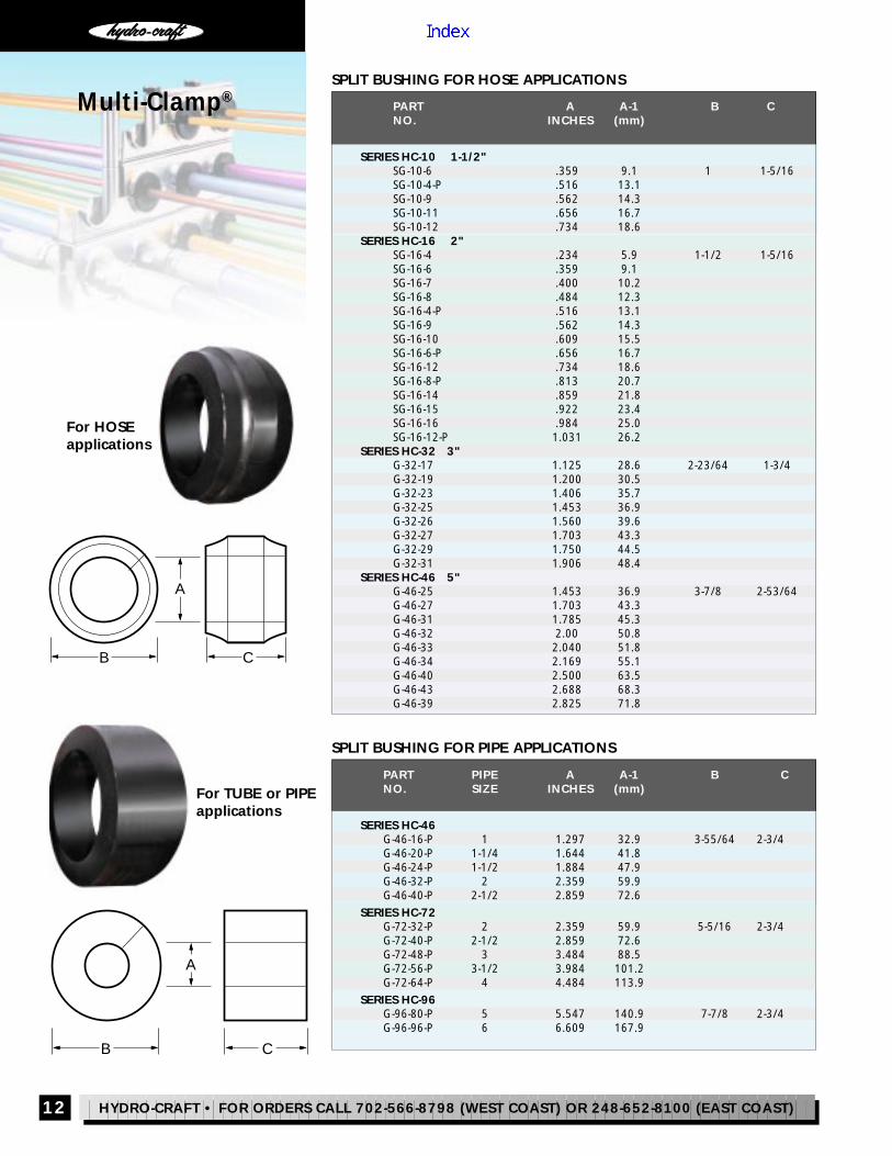
SPLIT BUSHING FOR PIPE APPLICATIONS
SPLIT BUSHING FOR HOSE APPLICATIONS
12
Multi-Clamp®
®
PART A A-1 B CNO. INCHES (mm)
SERIES HC-10 1-1/2"SG-10-6 .359 9.1 1 1-5/16SG-10-4-P .516 13.1SG-10-9 .562 14.3SG-10-11 .656 16.7SG-10-12 .734 18.6
SERIES HC-16 2"SG-16-4 .234 5.9 1-1/2 1-5/16SG-16-6 .359 9.1SG-16-7 .400 10.2SG-16-8 .484 12.3SG-16-4-P .516 13.1SG-16-9 .562 14.3SG-16-10 .609 15.5SG-16-6-P .656 16.7SG-16-12 .734 18.6SG-16-8-P .813 20.7SG-16-14 .859 21.8SG-16-15 .922 23.4SG-16-16 .984 25.0SG-16-12-P 1.031 26.2
SERIES HC-32 3"G-32-17 1.125 28.6 2-23/64 1-3/4
G-32-19 1.200 30.5G-32-23 1.406 35.7G-32-25 1.453 36.9G-32-26 1.560 39.6G-32-27 1.703 43.3G-32-29 1.750 44.5G-32-31 1.906 48.4
SERIES HC-46 5"G-46-25 1.453 36.9 3-7/8 2-53/64G-46-27 1.703 43.3G-46-31 1.785 45.3G-46-32 2.00 50.8G-46-33 2.040 51.8G-46-34 2.169 55.1G-46-40 2.500 63.5G-46-43 2.688 68.3G-46-39 2.825 71.8
PART PIPE A A-1 B CNO. SIZE INCHES (mm)
SERIES HC-46G-46-16-P 1 1.297 32.9 3-55/64 2-3/4G-46-20-P 1-1/4 1.644 41.8G-46-24-P 1-1/2 1.884 47.9G-46-32-P 2 2.359 59.9G-46-40-P 2-1/2 2.859 72.6
SERIES HC-72G-72-32-P 2 2.359 59.9 5-5/16 2-3/4G-72-40-P 2-1/2 2.859 72.6G-72-48-P 3 3.484 88.5G-72-56-P 3-1/2 3.984 101.2G-72-64-P 4 4.484 113.9
SERIES HC-96G-96-80-P 5 5.547 140.9 7-7/8 2-3/4G-96-96-P 6 6.609 167.9
For HOSEapplications
A
B C
For TUBE or PIPEapplications
A
B C

HYDRO-CRAFT • FOR ORDERS CALL 702-566-8798 (WEST COAST) OR 248-652-8100 (EAST COAST)
How To Order Select bypart number. *Add SS to end of partnumber for stainless steel
STANDARD PARTS*
THREAD ADAPTER (for installing or stacking)*
REDUCER ADAPTER (for stacking HC-10 on HC-32 series clamp)
PARTMULTI-CLAMP A B C D E F GNO.SERIES THREAD THREAD
HC-32 R-32 5/16-18 3/8-16 .75 1 .50 .575 2.25
WELD ADAPTER (for weld mounting)
SELF-TAPPING ADAPTER (for drilled hole mounting)
MULTI-CLAMP A B C D E F
SERIES THREAD
HC-10 & HC-16 ST-10 5/16-18 3/4 5/8 1/2 .577 1.50
SOCKET-HEAD STACKING NUT (one required for each mounting hole)*
MOUNTING ADAPTER (for pillar or spar mounting)
PART MULTI-CLAMP A B C D ENO. SERIES THREAD
HB-10 HC-10 & HC-16 5/16-18 7/32 1/2 0.577 3/4HN-10 5/16-18 17/64 1/2 0.577HB-32 HC-32 3/8-16 1/4 9/16 0.650 1HN-32 3/8-16 21/64 9/16 0.650HB-72 2/1-131-2/169 & 27 ,64-CHHN-72 1/2-13
AREHSAWKCOLHW-10 HC-10 & HC-16 5/16HW-32 HC-32 3/8HW-72 HC-46, 72 & 96 1/2
PARTMULTI-CLAMP A B C DNO.SERIES THREAD
HC-10 & HC-16 W-10 W-16 .44 .75 5/16-18 1HC-32 W-32 .47 1 3/8-16 1.25HC-46,72 & 96 W-72 .53 1.5 1/2-13 1.375
PARTMULTI-CLAMP A B C DNO.SERIES THREAD
HC-10 & HC-16 T-10 .62 .62 1.38 5/16-18HC-32 T-32 .88 .88 2 3/8-16HC-46,72 & 96 T-72 .50 .62 1.50 1/2-13
PARTMULTI-CLAMP A B C D E FNO.SERIES DIA. THREAD CHAMFER
HC-10 N-10 1.335 1/2 5/16-18 1/32x45 ° 5/16 7/32HC-16 N-16 1.800 1/2 5/16-18 1/32x45 ° 5/16 7/32HC-32 N-32 2.780 11/16 3/8-16 1/16x30 ° 3/8 9/32HC-46 N-46 4.500 1 1/2-13 1/16x30 ° 1/2HC-72 N-72 6.00 1 1/2-13 1/16x30 ° 1/2HC-96 N-96 8.750 1 1/2-13 1/16x30 ° 1/2
PARTMULTI-CLAMP A B C D E FNO.SERIES DIA. DIA. DIA. (± .003)
HC-10-1-1/2" B-10-MO 1 .8390 MAX 11/32 9/32 1-1/16 .510.8350 MIN
HC-16-2" B-16-MO 1-3/8 1.193 MAX 11/32 9/32 1-1/16 .5101.187 MIN
HC-32-3" B-32-MO 2-1/4 2.128 MAX 13/32 27/64 1-9/16 .6872.122 MIN
Multi-Clamp ®
13
®
FDE
C B A
CBDF
3/8
ABC
D
A
C
A
FA
E
D C
B
E
D
C
D
A
A
BE
B
CDG
B A
E
F
PARTNO.

HYDRO-CRAFT • FOR ORDERS CALL 702-566-8798 (WEST COAST) OR 248-652-8100 (EAST COAST)14
CLAMP NO. A B C
HCS-16-M 1.95 1.20 2.80
CLAMP NO. A B C
HCS-32-M 2.95 1.70 3.77
How To OrderSimply choose the clamp size, select no symbol for steel or SS forstainless steel, and the appropriate bushing size. Clamps andbushings are ordered separately.
Example: Clamp HCS-32-M - SS and Bushing RSG-32-10
This example would provide you with our larger, stainless steelclamp, and a bushing for 5/8” tube.
The Hydro-Strut Clamping System is the mosteffective clamp available - greatly reducing noisedue to line shock and vibration!
The Hydro-Strut clamping system is designedfor hydraulic, pneumatic, electrical, and fuel lineapplications, where it retains, guides, protects, andspaces line runs uniformly. This design can easilymaintain equal centers, even when the line size varies.Lines are rigid, have a neat appearance, and installeasily through channel mounting.
Independent testing shows the Hydro-Strut clampingsystem, using Styrene Butadiene Rubber (SBR) bush-ings, to be 80 percent more efficient at reducing noisethan conventional cushion clamping systems. TheSBR bushing, which provides the cushion for thereduced line noise, is compression molded, andselected for its excellent compatibility with industrialsolvents, fuels, and hydraulic fluids. The clamp isavailable in either stainless or plated steel.
Available standard sizes for tube, hose and pipe rangefrom 1/4-inch through 2-inch. Special sizes are avail-able, please contact the factory for more information.
®
Hydro-Strut®
Clamping System
Reduces line noise by asmuch as 80%Available in wide range of line sizes from 1/4" to 2"Easy installation throughchannel mountingHigh-quality materials ofconstruction
1.250
1.625
C
B
A
D
BUSHING TUBE D D-1No. SIZE INCHES (mm)
RSG-16-4 1/4 .234 5.9RSG-16-6 3/8 .359 9.1RSG-16-8 1/2 .484 12.3RSG-16-10 5/8 .609 15.5RSG-16-12 3/4 .734 18.6RSG-16-14 7/8 .859 21.8RSG-16-16 1 .984 25.0RSG-16-20 1-1/4 1.234 31.3
Pipe SizeRSG-16-4P 1/4 .516 13.1RSG-16-6P 3/8 .656 16.7RSG-16-8P 1/2 .813 20.7RSG-16-12P 3/4 1.031 26.2RSG-16-16P 1 1.297 32.9
BUSHING TUBE D D-1No. SIZE INCHES (mm)
RSG-32-6 3/8 .359 9.1RSG-32-8 1/2 .484 12.3RSG-32-10 5/8 .609 15.5RSG-32-12 3/4 .734 18.6RSG-32-14 7/8 .859 21.8RSG-32-16 1 .984 25.0RSG-32-20 1-1/4 1.234 31.3RSG-32-24 1-1/2 1.484 37.7RSG-32-32 2 1.984 50.4
Pipe SizeRSG-32-4P 1/4 .516 13.1RSG-32-6P 3/8 656 16.7RSG-32-8P 1/2 .813 20.7RSG-32-12P 3/4 1.031 26.2RSG-32-16P 1 1.297 32.9RSG-32-20P 1-1/4 1.640 41.7RSG-32-24P 1-1/2 1.870 47.5RSG-32-32P 2 2.350 59.7

HYDRO-CRAFT • FOR ORDERS CALL 702-566-8798 (WEST COAST) OR 248-652-8100 (EAST COAST) 15
®
A Critical Junction . . .. . . in any hydraulic system is the connectionpoint between tube and hose, hose and pipe, etc.Improperly secured, they will coldwork, loosen, andLEAK. The MULTI-CLAMP ® SYSTEM'S exclusive abilityto clamp the line AT THE FITTING is widely used andapproved in thousands of plants worldwide. Now,this exclusive advantage is available with Strut-Adapter.The specially designed bushing (shown below), securelyaccommodates the following Hydro-Craft junctionadapters: (see page 9 for dimensions)
• FEMALE S.A.E. straight thread size:3/4"-16.
• FEMALE NPT pipe thread size:3/8".
• MALE 37 ° Flared Junction Adapters:1/4", 3/8", 1/2", 5/8".
• MALE O-RING FACE SEAL, Tube Junction Adapters:3/8", 1/2", 5/8", 3/4".
Clamp available in plated steel and stainless steel.
How To OrderSelect by part number.Example: WS-BFM-10-6P
This example would provide you with our female NPT junctionadapter with a 3/8" �tting size. Add SS to end of part number forstainless steel clamp.
FITTING SIZE PART NO. A B C
FEMALE NPT JUNCTION ADAPTERS, HC-10 & HC-16 SERIES3/8" FEMALE NPT WS-BFM-10-6P 3/8 2.07 2.60
FEMALE SAE JUNCTION ADAPTERS, HC-10 & HC-16 SERIES3/4"-16 FEMALE SAE WS-BSAE-10-8 3/4 2.07 2.60
MALE 37 ° FLARED JUNCTION ADAPTERS, HC-10 SERIES1/4" MALE 37 ° FLARE WS-B-10-4 1/4 2.07 2.603/8" MALE 37 ° FLARE WS-B-10-6 3/8 2.07 2.601/2" MALE 37 ° FLARE WS-B-10-8 1/2 2.07 2.605/8" MALE 37 ° FLARE WS-B-10-10 5/8 2.07 2.60
MALE O-RING FACE SEAL, TUBE JUNCTION ADAPTERS, HC-10 SERIES3/8" MALE WS-FB-10-6 3/8 2.07 2.601/2" MALE WS-FB-10-8 1/2 2.07 2.605/8" MALE WS-FB-10-10 5/8 2.07 2.603/4" MALE WS-FB-10-12 3/4 2.07 2.60
B
C
1.250
1.625
A
All dimensions are approximate in inches
Installation is a snap -clamp, �tting, and cushionare all packaged togetherand clearly labeled
Strut-Adapter ®

HYDRO-CRAFT • FOR ORDERS CALL 702-566-8798 (WEST COAST) OR 248-652-8100 (EAST COAST)
Walker-Strut®
The Channel MountedClamp from Hydro-Craft®
Reduces:
• VIBRATION• SHOCK• SURGE• EXPANSION AND CONTRACTION
16
Hydro-Craft® WALKER-STRUT® ChannelChannel is used to mount Strut-Adapter, Hydro-Strut,Silent-Strut, and Walker-Strut Clamps. Steel Single-Anchor Channel, 14 ga. x 13/16 x 1-5/8" with greenbaked-on finish. Also available in 304 stainless steel.
Available in precut lengths: 3', 4', and 10'. Special cutsizes available, please call for quote.
PLEASE NOTE: Long channel shipped with a combined length and girth of120" or more must ship by common carrier. Cut-to-size orders may there-fore cost less due to shipping via U.P.S.
The WALKER-STRUT® CLAMPING SYSTEM is ideal forline runs through 6" where space is at a premium,or where severe shock and vibration is not present.Used now for several years in the fluid powerindustry, it has been proven time and again as themost sensible, most economical, most trouble-freerail-mounted clamp available. The Walker-Strut isalso widely used in the refrigeration and mobileindustries.
The WALKER-STRUT ClampClamps are available in plated steel and stainless steel.
The BushingManufactured from a thermoplastic elastomer,it's built tough to withstand the effects of most oils,chemicals and industrial cleaning compounds, intemperatures from – 20oF to 275oF.
InstallationOne man, one tool time savings. Retrofits can beadded without disassembling your present system.
Despite its exclusive benefits, the Walker-Strut Systemfrom Hydro-Craft is priced competitively. Installation isa snap: simply mount the base channel, position theclamp, and tighten!
WALKER-STRUT assemblies are available 5 sets perbag. Larger quantities can be shipped in bulk.
®
HYDRO-CRAFT • FOR ORDERS CALL 702-566-8798 (WEST COAST) OR 248-652-8100 (EAST COAST) 17
C
B
D
A
1.25
1.62
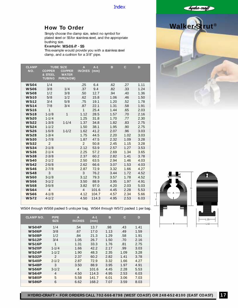
How To OrderSimply choose the clamp size, select no symbol forplated steel or SS for stainless steel, and the appropriatebushing size.Example: WS-06-P - SSThis example would provide you with a stainless steelclamp, and a cushion for a 3/8” pipe.
®
Walker-Strut®
CLAMP TUBE SIZE A A-1 B C D NO. COPPER COPPER INCHES (mm)
& STEEL WATERTUBING PIPE(NOM)
WS-04 1/4 .25 6.4 .62 .27 1.11WS-06 3/8 1/4 .37 9.4 .82 .33 1.24WS-08 1/2 3/8 .50 12.7 .94 .40 1.36WS-10 5/8 1/2 .62 15.8 1.06 .46 1.50WS-12 3/4 5/8 .75 19.1 1.20 .52 1.78WS-14 7/8 3/4 .87 22.1 1.31 .58 1.91WS-16 1 1 25.4 1.44 .65 2.03WS-18 1-1/8 1 1.12 28.5 1.57 .70 2.16WS-20 1-1/4 1.25 31.8 1.70 .77 2.30WS-22 1-3/8 1-1/4 1.37 34.8 1.82 .83 2.75WS-24 1-1/2 1.50 38.1 1.95 .90 2.75WS-26 1-5/8 1-1/2 1.62 41.2 2.07 .96 3.03WS-28 1-3/4 1.75 44.5 2.20 1.02 3.03WS-30 1-7/8 1.87 47.5 2.32 1.09 3.28WS-32 2 2 50.8 2.45 1.15 3.28WS-34 2-1/8 2.12 53.9 2.57 1.27 3.53WS-36 2-1/4 2.25 57.2 2.69 1.34 3.65WS-38 2-3/8 2.37 60.2 2.82 1.41 3.78WS-40 2-1/2 2.50 63.5 2.94 1.46 4.03WS-42 2-5/8 2.62 66.6 3.07 1.53 4.03WS-46 2-7/8 2.87 72.9 3.32 1.66 4.27WS-48 3 3 76.2 3.44 1.72 4.52WS-50 3-1/8 3.12 79.3 3.57 1.78 4.52WS-56 3-1/2 3.50 88.9 3.95 1.97 4.91WS-58 3-5/8 3.82 97.0 4.20 2.03 5.03WS-64 4 4 101.6 4.45 2.28 5.53WS-66 4-1/8 4.12 104.7 4.57 2.34 5.66WS-72 4-1/2 4.50 114.3 4.95 2.53 6.03
CLAMP NO. PIPE A A-1 B C DSIZE INCHES (mm)
WS-04P 1/4 .54 13.7 .98 .43 1.41WS-06P 3/8 .67 17.0 1.13 .49 1.59WS-08P 1/2 .84 21.3 1.29 .58 1.91WS-12P 3/4 1.05 26.7 1.50 .70 2.16WS-16P 1 1.31 33.3 1.76 .81 2.75WS-20P 1-1/4 1.66 42.2 2.17 .99 3.03WS-24P 1-1/2 1.90 48.3 2.35 1.09 3.28WS-32P 2 2.37 60.2 2.82 1.41 3.78WS-40P 2-1/2 2.87 72.9 3.32 1.66 4.27WS-48P 3 3.50 88.9 3.95 1.97 4.91WS-56P 3-1/2 4 101.6 4.45 2.28 5.53WS-64P 4 4.50 114.3 4.95 2.53 6.03WS-80P 5 5.58 141.7 6.01 3.06 7.03WS-96P 6 6.62 168.2 7.07 3.59 8.03
WS-04 through WS-58 packed 5 units per bag. WS-64 through WS-72 packed 1 per bag.

HYDRO-CRAFT • FOR ORDERS CALL 702-566-8798 (WEST COAST) OR 248-652-8100 (EAST COAST)18
All dimensions are approximate in inches
®
How To OrderSimply choose the clamp size and the appropriate bushing size.Clamps and bushings are ordered separately.
Example: Clamp HC-SS-16 and Bushing G-16-10
This example would provide you with our smaller Zytel® glass-filled nylon clamp and a bushing for 5/8" tube.
The Silent-Strut clamping system is excellent for use inrefrigeration, HVAC and electrical applications, but isalso effective on hydraulic, pneumatic and fuel lineapplications. In addition to its low cost, it offersexcellent noise reduction due to the materials ofconstruction and design of the channel mountingsystem. This channel mounting makes for a quick andeasy installation. The superior design will maintainequal centers, even when the line size varies.Lines remain rigid and have a neat appearance.
The clamp is made from Zytel® (glass-filled nylon) thatis very resistant to corrosion, and much lower in costthan stainless steel. Two clamp sizes are available. Allthe bushings are made from Styrene Butadiene Rubber(SBR). The bushing is secured in the clamp usingstainless steel nuts and bolts. The SBR bushing iscompression molded, selected for its compatibility withmost oils, chemicals, and cleaning compounds, andprovides the cushion for the noise reduction.
Available standard sizes for tube and pipe range from1/4-inch through 2-inch. Please contact the factoryfor more information.
CLAMP NO. A B C
HC-SS-32 2.82 1.87 4 5/8
CLAMP NO. A B C
HC-SS-16 1.50 1.25 3 3/8
Bushing TUBE D D-1No. SIZE INCHES (mm)
G-16-4 1/4 .234 5.9G-16-5 5/16 .297 7.5G-16-6 3/8 .359 9.1G-16-8 1/2 .484 12.3G-16-10 5/8 .609 15.5G-16-12 3/4 .734 18.6G-16-14 7/8 .859 21.8G-16-16 1 .984 25.0
Pipe SizeG-16-4-P 1/4 .516 13.1G-16-6-P 3/8 .656 16.7G-16-8-P 1/2 .813 20.7G-16-12-P 3/4 1.031 26.2
Bushing TUBE D D-1No, SIZE INCHES (mm)
G-32-4 1/4 .234 5.9G-32-6 3/8 .359 9.1G-32-8 1/2 .484 12.3G-32-10 5/8 .609 15.5G-32-12 3/4 .734 18.6G-32-14 7/8 .859 21.8G-32-16 1 .984 25.0G-32-20 1-1/4 1.234 31.3G-32-24 1-1/2 1.484 37.7G-32-28 1-3/4 1.734 44.0G-32-32 2 1.984 50.4
Pipe SizeG-32-4-P 1/4 .516 13.1G-32-6-P 3/8 .656 16.7G-32-8-P 1/2 .813 20.7G-32-12-P 3/4 1.031 26.2G-32-16-P 1 1.297 32.9G-32-20-P 1-1/4 1.641 41.7G-32-24-P 1-1/2 1.875 47.6
B
A
C
1.250
1.625
D
Silent-Strut®
Clamping System
Easy channel mountinginstallationWide range of line sizes from1/4" to 2"High-quality materials ofconstructionGreatly reduces line noise
EXCLUSIVE TO HYDRO-CRAFT

HYDRO-CRAFT • FOR ORDERS CALL 702-566-8798 (WEST COAST) OR 248-652-8100 (EAST COAST) 19
Hydro-Clamp SystemRoutes Line Runs Simplyand Inexpensively
• Easy to use, modularclamping system
• Interchangeable withother major brands
• Wide range of sizes, from1/4” through 8”
• Available in standard, heavy,and twin configurations, inpolypropylene, aluminum*,and polyamide*
• Optional stainless steelclamp available
• For use with tube, pipe,and metric sizes
• Meets DIN SPEC 3015• DIN rails are available to
complete your system
Top Cover Plate
DIN Rail Nut
Weld Plate
Stacking Bolt
Insert
DIN Rail
®
How to Order
Build an ordering code as follows:Example: A-H-P-24P-OC-HS-SS
Hydro-Clamp = AClamp SeriesHeavy = HStandard = STwin = TStandard with onemounting hole = OInsert Material
Polypropylene = PPolyamide* = PMAluminum* = ANone = XSize (Specify size, then type)Tube = No SymbolPipe = PMetric = MMounting HardwareWeld Plate = WDIN Rail Nut = RTop Cover Plate Only = OCWeld with Top Cover Plate = WCNo Mounting Hardware = XHardware Components (Metric)Hex Bolt = HHex Bolt with Spacers = HSStacking Bolts = SStacking Bolts with Lock Plate = SLAllen Bolts = ALocking Plate Only = LSpacer Only = SPNo Hardware Components = XStainless Steel ClampStainless Steel Clamp* = SSNone = No Symbol
*Special order
DIN Rails - Order Separately28 x 14 x 2 Meters = D-RAIL-S40 x 22 x 2 Meters = D-RAIL-H
Tube (Inches) Pipe (Inches) Metric(OD) (Nominal Bore) (OD)
Standard Series1/4 to 3-1/2 1/8 to 2 6 to 102
Heavy Series1/4 to 8 1/8 to 8 6 to 324
Twin Series1/4 to 1-1/2 1/4 to 1-1/4 6 to 42
DISCONTINUED!

How To OrderSimply choose the bushing number and appropriate strapnumber that corresponds to the tube or pipe size you need.Bushings and pipe straps are ordered separately .Example: Bushing EI-10-12 and Strap EIM-10
This would provide you with the bushing and strap to �t a 3/4" tube.
20All dimensions are approximate in inches
Econo-IsolatorClamping SystemThe Econo-Isolator clampingsystem o�ers a low-cost, high-quality solution for use inplumbing, mechanical, andHVAC/R applications.
Easy mounting using readily-available bracketsMade from high-quality StyreneButadiene Rubber (SBR)
Inexpensive Cushions To Fit Standard Pipe StrapsThe Econo-Isolator not only meets the requirements forplumbing, mechanical, and HVAC/R applications, butperforms well in hydraulic, pneumatic, fuel line, andelectrical applications.
The Econo-Isolator, using standard pipe straps that arereadily available, retains, guides, protects and spaces lineruns uniformly. Lines are rigid, have a neat appearance,and install easily. The bushing is made from StyreneButadiene Rubber. It is compression molded and selectedfor its excellent compatibility with industrial solvents, fuels,hydraulic �uids, other liquids and gases.
B
A
A
C B
D
B
A
2-Hole Straps
1-Hole Straps
Bushing Tube A B C D D-1)mm()sehcnI(eziS.oN
EI-10-04 1/4 .870 .835 1.0 .235 5.91.9063.8/301-IE -063.21584.2/108-01-IE5.51016.8/501-01-IE6.91537.4/321-01-IE
Pipe Size3.31525.4/1P04-01-IE7.61066.8/3P06-01-IE
Tube SizeEI-16-14 7/8 1.30 1.24 1.0 .860 21.8
6.52589.161-61-IE
Pipe Size0.12528.2/1P08-61-IE2.62530.14/3P21-61-IE
Bushing Tube A B C D D-1)mm()sehcnI(eziS.oN
EI-32-18 1-1/8 2.38 2.37 1.50 1.110 28.23.13532.14/1-102-23-IE5.43063.18/3-122-23-IE7.73584.12/1-142-23-IE9.04016.18/5-162-23-IE0.44537.14/3-182-23-IE2.74068.18/7-103-23-IE4.05589.1223-23-IE6.35011.28/1-243-23-IE
Pipe Size0.33003.11P61-23-IE8.14546.14/1-1P02-23-IE8.74588.12/1-1P42-23-IE
1 Hole Strap Size A BNo. (Inches)
EIM-10-1 1/2" 1.85 0.9EIM-16-1 1" 2.7 1.4EIM-32-1 2" 4.7 2.325
2 Hole Strap Size A BNo. (Inches)
EIM-10 1/2" 2.438 0.81EIM-16 1" 3.375 1.285EIM-32 2" 4.7 2.325
®
* Add -SS to strap part numbers for stainless steel straps.
HYDRO-CRAFT • FOR ORDERS CALL 702-566-8798 (WEST COAST) OR 248-652-8100 (EAST COAST)

®
HYDRO-CRAFTHYDRO-CRAFTCATALOG
LineClampingSystems
42

Check Out Our Products & Accessories Catalog

320 Sunpac Ct.Henderson, Nevada 89011 Tel (702) 566-8798Fax (702) 566-9285
1821 Rochester Industrial Drive,Rochester Hills, Michigan 48309Tel (248) 652-8100Fax (248) 652-0343
WWW: http://www.hydro-craft.comE-mail: [email protected]
®
HYDRO-CRAFT INC.
Hydro-Craft was established in 1958 ina small shop in Detroit, Michigan as amanufacturer of quality hydraulic tanks.Over the years we have expanded ourproduct line and our facilities. We currentlyhave two state-of- the art plants located inRochester Hills, Michigan and Henderson,Nevada. From these two points, we canship our product conveniently to anylocation worldwide.
In addition to our line clamp systems,the Hydro-Craft product line includesstock and custom hydraulic reservoirs,
breather caps, sight level gages, kits, shock mounts, pump/motor
mounts, manifolds, and many morehydraulic accessories.
The dedication to providing our customerswith quality parts and service has onlygrown stronger over the years. We thankyou for your interest in our products.