incremental reconstruction of urban environments by edge ... · incremental reconstruction of urban...
TRANSCRIPT

Incremental Reconstruction of Urban Environmentsby Edge-Points Delaunay Triangulation
Andrea Romanoni1 and Matteo Matteucci2
Abstract— Urban reconstruction from a video captured bya surveying vehicle constitutes a core module of automatedmapping. When computational power represents a limitedresource and, a detailed map is not the primary goal, thereconstruction can be performed incrementally, from a monoc-ular video, carving a 3D Delaunay triangulation of sparsepoints; this allows online incremental mapping for tasks suchas traversability analysis or obstacle avoidance. To exploitthe sharp edges of urban landscape, we propose to use aDelaunay triangulation of Edge-Points, which are the 3D pointscorresponding to image edges. These points constrain the edgesof the 3D Delaunay triangulation to real-world edges. Besidesthe use of the Edge-Points, a second contribution of this paper isthe Inverse Cone Heuristic that preemptively avoids the creationof artifacts in the reconstructed manifold surface. We force thereconstruction of a manifold surface since it makes it possible toapply computer graphics or photometric refinement algorithmsto the output mesh. We evaluated our approach on four realsequences of the public available KITTI dataset by comparingthe incremental reconstruction against Velodyne measurements.
I. INTRODUCTION
Urban 3D reconstruction represents a fundamental task ofmany robotics applications, e.g, city mapping [1] or city seg-mentation [2] from a surveying vehicle. Most of the existingsystems propose computationally expensive stereo methodsthat build a very detailed reconstruction by estimating densekeyframe depth maps , usually by means of GPU computing[1], [3]. However, in some robotics applications, a monocu-lar, rough and computationally less expensive reconstructionis preferred, for instance, let consider traversability analysisperformed on embedded CPU-only systems deployed with asingle camera.
Space carving [4] thus becomes an effective method tobuild a large urban map quickly. It usually bootstraps from asparse point cloud, estimated, for instance, through Structurefrom Motion [5]. Out of this sparse point cloud space carvingbuilds a convenient partition of the space, usually a 3D De-launay triangulation, where each part, e.g., the tetrahedron,is initialized as matter. Then, a ray tracing procedure marksas free space the parts crossed by a camera-to-point viewingray, i.e., the segment from a camera center to a 3D point inthe triangulation.
Existing literature proposes both batch [6] and incremental[7], [8] space carving methods. The former perform thereconstruction by taking into account all the viewing rays at
1DEIB, Politecnico di Milano, Via Ponzio 34/5, 20133, Milano, [email protected]
2DEIB, Politecnico di Milano, Via Ponzio 34/5, 20133, Milano, [email protected]
(a)
(b)Fig. 1. Different features extracted on the same image: (a) shows 3609Harris corners, (b) shows 3595 Edge-Points.
the same time; the latter carve the space incrementally, i.e.,frame-by-frame. In our case we focus on the incrementalapproach, since we address the scenario of a surveyingvehicle that builds its own map of the city while navigatingthrough it.
The authors in [8] and [7] propose two incremental spacecarving algorithms based on the 3D Delaunay triangulationof sparse 3D point clouds. In [8] the estimated surface issimply the boundary between free space and matter; on theother hand in [7], and its extension [9], the estimated surfaceis forced to be manifold, i.e., for each vertex, the neighboringtriangles are homeomorphic to a disk.
Several reasons lead to enforce the manifold property.First, most computer graphics algorithms need the manifoldproperty to hold, one example is the Laplace-Beltrami op-erator [10]. Moreover, photometric surface refinement as in[11] and [12] usually needs surface manifoldness to properlycompute the gradient flow that minimizes the photometricerror. Finally, non-manifold surfaces are usually not realisticin real world environments.
In this paper, we improve on the approach of [7] to extracta manifold incrementally. Differently from [7], instead ofreconstructing 3D points corresponding to Harris features,we propose to build the 3D Delaunay triangulation on thepoints projecting on the (Canny) edges of the images, namedEdge-Points (see Fig. 1). The existing incremental spacecarving systems, e.g., [9], [7], [8], rely on sparse pointcloud estimated by Structure from Motion, which discardsthe Edge-Points.
The main drawback of these points is the degree offreedom along the edge itself that usually causes instabilityin estimation and matching. Nevertheless, several reasons
arX
iv:1
604.
0623
2v2
[cs
.CV
] 2
7 A
pr 2
016

(a)
(b)
(c)Fig. 2. Reconstructions with (a) Harris corners, (b) Edge-Points, and (c)textured reconstruction.
supports the usage of Edge-Points. First, urban scenariosshow lot of sharp edges, therefore Edge-Points representsuitable vertexes to constrain the edges of the 3D Delaunaytriangulation to real-world edges (see Fig. 2). Then, as Fig. 1shows, Edge-Points provide a better coverage of the image.Finally, the number of Edge-Points is easier to tune withrespect to the classical feature detector: by changing thedownsampling rate we change proportionally the number ofEdge-Points.
Other authors [13], [14] already took advantage of Edge-Points in their systems. Rhein et al. in [13] propose aheterogeneous (corner features and Edge-Points) tracker thatexploits the epipolar constraint, but, differently from us, theirwork is focused on the tracking stage and it aims at a sparsepoint cloud reconstruction. Tomono [14] uses Edge-Points tomake the Simultaneous Localization And Mapping (SLAM)process robust in an indoor scenario that exhibits a lack oftexture, but he does not reconstruct the 3D surface of thescene, moreover it uses a stereo rig that makes the estimationof the 3D point positions easier with respect to the monocularcase addressed in this paper.
The use of a monocular camera looking forward induceslow parallax which makes the estimation of the 3D pointpositions not a trivial task. This issue adds to the previouslymentioned Edge-Points instability. In this paper we show thatthe combination of the Kanade-Lucas-Tomasi (KLT) tracker[15], a convenient filtering of the matches, and Gaussian-Newton optimization successfully handle Edge-Points esti-mation even in this complex scenario.
Our system bootstraps from a good estimate of the cameraposes, as in many urban 3D reconstruction systems [1], [3].We assume the camera pose estimation could be obtainedwith a Structure from Motion or SLAM technique, e.g., [5],or with an estimate obtained by fusing GPS, inertial sensorsand visual odometry such as in [16]. This assumption enables
us to estimate independently, and very efficiently, the 3DEdge-Point positions.
Besides the use of Edge-Points, a second contribution inthis paper addresses the visual artifacts issue that sometimesaffects the estimated surface. This issue was deeply studiedin [9], where the authors propose an ad hoc post-processingprocedure that attempts to detect and remove the artifactsby preserving the manifold property; it runs quite fast, butits computational complexity is not negligible (0.43s per-frame). In this paper we propose a very efficient heuristic topreemptively avoid visual artifacts, which runs significantlyfaster than the previously mentioned procedure (around0.001-0.010s per-frame). We named this heuristic InverseCone Heuristic since the space affected by the heuristic hasthe shape of a cone directed inversely with respect to camera-to-point viewing ray.
In Section II we summarize the approach of [7] to re-construct a manifold surface. In Section III we describeour incremental reconstruction system, focusing on the 3DEdge-Point cloud estimation and the preemptive approachto remove the visual artifacts. In Section IV we show theexperimental results on the public available dataset KITTI[17], while in Section V we conclude the paper.
II. MANIFOLD RECONSTRUCTION
We are interested in reconstructing a manifold surfacein the 3D space which represents the observed scene. Asurface is manifold if and only if the surface neighborhoodof each point is homeomorphic to a disk. In the discrete case,the points are the vertexes of the mesh, while the incidenttriangles (or polygons) form the neighborhood. So, a discretesurface is manifold if each vertex v is regular, i.e., if andonly if the edges opposite to v form a closed path withoutloops [18].
A. Incremental manifold extraction
In this section we briefly summarize the method intro-duced in [7] and [9], which, in this paper, we enhancesignificantly by choosing a proper point cloud to build theDelaunay triangulation and by avoiding most of the artifactsin the estimated surface with the Inverse Cone Heuristic.
In [7], the authors bootstrap the surface reconstructionfrom a manifold by partitioning the 3D triangulation of thespace between the set O of outside tetrahedra, i.e., the man-ifold subset of the free space (not all free space tetrahedrawould be included in this set), and the complementary setI of inside tetrahedra, i.e., the remaining tetrahedra thatroughly represent the matter.
Let δ(Otinit) be the initial manifold, i.e., the boundarybetween O and I , estimated as it follows:
• Point Insertion: add all the 3D points estimated up totime tinit and construct their 3D Delaunay triangulation;
• Ray Tracing: mark the tetrahedra as free space accord-ing to the viewing rays: the list of these tetrahedra isnamed Ftinit ;
• Growing: initialize a queue Q with the tetrahedron∆1 ∈ Ftinit that gets the highest number of viewing ray

intersections; then iterate the following procedure untilQ is empty: (a) remove the tetrahedron ∆curr with thehighest number of viewing ray intersections from Q;(b) add it to Otinit only if the resulting δ(Otinit ∩∆curr)is manifold; (c) add to the queue Q its neighboringtetrahedra that are not already inside the Otinit set.
Once the system is initialized, a new set of points Ptk
is generated at tk = tinit + k ∗ Tk, where k ∈ N+ isthe keyframe index and Tk is the period. The insertionof each point p ∈ Ptk would cause the removal of a setDtk of the tetrahedra that invalidates the Delaunay property;the surface δ(Otk) = δ(Otk−1
\ Dtk) is not guaranteedto be manifold anymore. To avoid this, the authors in [7]define a new list of tetrahedra Etk ⊃ Dtk and apply theso called Shrinking procedure, i.e., the inverse of Growing:they subtract iteratively form Otk−1
the tetrahedra ∆ ∈ Etk
keeping the manifoldness valid. After this process, it is likelythat Dtk ∩Otk = ∅; however, in the case of Dtk ∩Otk 6= ∅the point p is not added to the triangulation. Once all pointsin Ptk have been added (or dropped), the growing processruns similarly to the initialization procedure, but the queueQ is initialized with the tetrahedra ∆ ∈ T \ O such that∆ ∩ δO 6= ∅.
III. 3D RECONSTRUCTION WITH EDGE-POINT ANDINVERSE CONE HEURISTIC
3D reconstruction with space carving entails space dis-cretization. We choose the 3D Delaunay triangulation to par-tition the space into tetrahedra since it has been recognizedin the literature to be a convenient representation for scenereconstruction [7], [6], [19], [8]. In the following we showhow we choose and we estimate the sparse point cloud uponwhich the triangulation is created and how we convenientlycarve the space to preemptively avoid artifacts in a novelway that deeply differs from the approach of [9].
A. Edge-Points for 3D Delaunay triangulation
A key aspect for a 3D reconstruction pipeline, not stressedenough in the literature, is the choice of the points on whichthe Delaunay triangulation is built, i.e., what kind of pointsmade up the sparse point cloud.
As most of man-made environments, urban scenarios showa lot of sharp edges, e.g., the corners of building facades,the borders of windows, or the silhouettes of parked cars.Existing 3D space carving systems do not leverage on thisinformation, but they rely only on maximally stable points.Stable points are suitable features to track, however, a recon-struction relying on them over-simplifies the reconstructedworld: it mostly fails to capture the sharp edges which donot show sharp corners too.
We propose to overcome this limitation by estimating the3D position of Edge-Points, so to constrain the edges of the3D triangulation to lay close to real-world 3D edges. Thisnovel triangulation generates a carved space more faithful tothe real-world scene, see for instance the difference of thetruck of Fig. 3(a) reconstructed with the use of Harris corners
(a) (b)
(c) (d)
Fig. 3. Three examples of reconstruction from sparse data of the lighttruck in (a): with Harris corners in (b), with Edge-Points with downsamplerate 1
40in (c) and Edge-Points with downsample rate 1
10in (d).
in Fig. 3(b), and with the Edge-Points at a low ( 140 ) and high
( 110 ) downsampling rate in Fig. 3(c) and 3(d) respectively.
Fig. 1 shows that some Edge-Points have been induced bygrass and shadows on the road plane. Even if this subset offeatures will not lay on real-world edges, their presence doesnot affect the quality of the reconstruction, since they lay, orare close, to the actual matter. Nevertheless most of thesepoints, especially those induced by the grass, get extractedalso by the Harris corner detector. Let stress one more timehere that most of the Edge-Points lay on the real-worldedges, while the Harris corners do not locate them very well.Another important point is that is easy to increment the num-ber of Edge-Points used to reconstruct the environment bykeeping the feature quality unchanged, while the corner-likefeatures quality usually degrades as soon as other featuresare required. To verify this, in the experimental section wetested our algorithm with two different downsampling ratesshowing that the quality of the reconstruction significantlyimproves as the sampling rate increases.
B. Edge-Points tracking and reconstruction
In Fig. 4 we depict the tracking and estimation process.For each keyframe, i.e., one frame every Tk, we extract the2D Edge-Points by (a) estimating the image edges with theCanny algorithm, and (b) downsampling those edges withstep Tedges, i.e., we downsample the chains of pixels thatmade up the edges. Then we track these points in consecutiveframes (both in keyframes and non-keyframes). Each track,i.e., the sequence of point 2D positions in subsequent images,contains the measurements of a 3D point. The value ofTk depends on the camera speed; in our case of surveyingvehicle, is fixed such that we have two keyframe per-second.
We track the 2D Edge-Points with the KLT tracker [15]as suggested by Rhein et al. [13] because it enables fasterreconstruction with respect to more complex trackers which,for instance, relies on SIFT descriptor computation. KLT

2D Edge-Pointsextraction
filtercorrespondencesthrough epipolar
constraint
KLT tracking
2D Edge-Points
keyf
ram
e
frame
ended
tracks
videoremove
short tracks
filter nearestcorrespondences
3D Edge-Pointsestimation
Fig. 4. Edge-Point tracking and estimation process.
tracks successfully most of the 2D Edge-Points between twoconsecutive frames; however, to reach good 3D point positionestimates, we need to take into account errors due to the lowparallax induced by the forward motion of the monocularcamera and we need to filter out wrong correspondencesproduced by the mentioned edge instability.
The low parallax issue affects the estimation processwhen the camera looks towards the moving direction. Theuncertainty of the 2D point measurement on the image planeis usually assumed to be Gaussian, so the measurementuncertainty spreads in the 3D space, through the uncertaintyellipse on the image plane, as a cone whose vertex is inthe camera center. When the parallax is low, the uncertaintycones of consecutive measurements of a 3D point are almostoverlapped [20]. As the intersection of these uncertainty conebecomes relevant, the 3D point position estimation is nomore reliable.
To ensure an overall significant parallax and to success-fully estimate the 3D points position, we filter the tracks bothat a local and at a global level. At a local level we filter outan Edge-Point when the displacement of its two consecutivemeasurements is too small, i.e., when the parallax is almostnull and the uncertainty of its estimate tends to infinite. Weexperimentally set this minimum displacement to dmin
meas =5pixels on our videos, but this parameter is related to thevideo frame rate and the camera focal length so it should beadapted according to the specific setup. Usually, as expectedfrom the forward motion, the points filtered out lay aroundthe center of the image, where the parallax is lower.
At a global level we discard also short tracks, i.e., thosetracks containing less then lmin
track measurements (we recallhere that a track is the sequence of measurements of a3D Edge-Point in subsequent images), where in our setuplmintrack = TK (recall that TK is the keyframe period).
To add robustness to the tracking step and manage thewell-known instability of Edge-Points we drop the corre-spondences that do not satisfy the epipolar constraint. Letxt−1 and xt be two corresponding points in frame t− 1 andt, and F the fundamental matrix between the camera at timet− 1 and t, the following equation holds:
xTt−1Fxt = 0.
Given Kt−1 and Kt the intrinsic parameters of the twocameras, which are the same in the monocular case, andassuming the world reference frame fixed in camera t − 1and P = [Rt, tt] to be the pose of camera t, the fundamental
matrix can be computed as:
F = K−Tt RtK
Tt−1[Kt−1Rttt]x
where [.]x is the skew-symmetric operator [20]. Given a pointxt−1 and the matrix F , the vector lt = Fxt−1 is the epipolarline, i.e., the locus of the points corresponding to xt−1 in theimage plane of camera t.
The epipolar constraint states that, given a point xt−1,the corresponding point xt lies on the epipolar line. So,given the KLT correspondence xt−1-xt, we drop it ifdistL2
{Fxt−1, xt} < εe, where εe is fixed to a tolerant valueof εe = 20px due to the noise of the epipolar contraintestimation induced by the forward motion. The epipolarconstraint represents a necessary, but not sufficient condition.The remaining wrong correspondences will be filtered duringthe 3D point estimation step.
The previous filtering approach is intended to deal withalmost-static scene so it filters out most of the dynamicobjects. This behavior is especially suitable for mappingpurposes: in this case the map usually has not to includedynamic object such as moving cars or pedestrians.
Parallel 3D Point Positions Estimation: Several spacecarving reconstruction algorithms adopt a Structure fromMotion technique to estimate both the camera pose andthe 3D points position at the same time, see for instance[21], [7] and [8]. On the other hand, in urban applications,especially those involving autonomous vehicles, a very goodestimate of the camera pose can be derived from sensorsthat are different from the camera itself (for instance withthe sensor fusion technique in [16]). Therefore, as in manyurban reconstruction systems ([1], [3]) we assume the camerapose to be known, while triangulating the 3D edge-points.This assumption allows to estimate the 3D position of each3D Edge-Point independently, i.e., in parallel.
After the tracking process, for each Edge-Point we firstestimate a rough 3D position by triangulating the first andlast measurements with the classic algorithm proposed byHartley and Sturm [22]. We then optimize this 3D positionestimate with a Gauss-Newton algorithm by minimizing the3D reprojection error over the whole track (we fixed anumber of NGN = 50 iterations):
e(X3D)i = P i ·X3D − ximeas,∀i ∈ track (1)
where P i is the i-th camera matrix, X3D is the 3D positionof the point to be estimated, and ximeas is the measurement inthe i-th image. Since some wrong correspondence could ex-ist, we drop the Edge-Points for which the mean reprojectionerror is higher then εGN = 2px at the end of optimization.
C. Inverse Cone Heuristic for preemptive visual artifactsremoval.
Once the 3D Edge-Points have been estimated, we proposean enhanced version of the algorithm in [7] to reconstruct amanifold surface. The surface extracted with the algorithmdescribed in Section II is affected by visual artifacts. Fig. 5shows a simple scenario where a visual artifacts is generateddue to the order of tetrahedra addition to the manifold. The

B, 0.0
E, 0.0
A, 9.0D, 5.5
C, 6.0B, 0.0
E, 0.0
A, 9.0D, 5.5
C, 6.0
(a) (b)Fig. 5. Simple scenario where a visual artifact is generated. Each triangleis labelled as “name, weight”. The bold red line is the boundary betweeninside (dark triangles) and outside (white triangles) sets. Bootstrapping from(a), the triangle A is added to the manifold in (b), then neither C or D canbe added anymore without invalidating the manifold property.
w1w2 w3
w3 2 .
M
(a) (b)Fig. 6. The inverse cone heuristic applied to the ray tracing step. On theleft the inverse cone, and on the right our implementation in the Delaunaytriangulation domain. Darker blue corresponds to higher weights.
algorithm bootstraps from the manifold in Fig. 5(a); then itgrows the manifold by we add the triangle A (Fig. 5(b)).Afterward, C and D are free space but they are kept in theinside set, otherwise they invalidate the manifold property;this two triangles make up a visual artifact.
In our case the visual edges which are critical for thereconstruction quality are those containing at least one edgelong enough to be considered unrealistic. More formally,Litvinov and Lhuiller, in [9], define a critical visual artifactas a set of tetrahedra belonging to the free space, but notincluded in the outside set and which contains at least onevisually critical edge, i.e., an edge ab such that exists acamera center c such as acb > α, where α is a user definedparameter (in our algorithm we do not need to define thisparameter).
Litvinov and Lhuiller in [9], propose a post-processingmethod to detect and remove critical artifacts keeping themanifold property valid. In this paper, we propose a pre-emptive approach significantly different, and complementary,with respect to [9]. Our idea relies on two observations: thetetrahedra that likely turn into visually critical edges are bigtetrahedra since they contains long edges, and big tetrahedraare mostly close to the camera path.
As the example of Fig. 5 shows, the order of growing isa key point to avoid the creation of visual artifacts; thus,by modifying the ray tracing step, we aim preemptivelyenforce a carving order such that big tetrahedra near to thecamera become the first to be added to the reconstructedmanifold. We replace the intersection count associated toeach tetrahedron with a weight. Ideally in the continuousspace, we would apply a cone-shaped weighting heuristic,we named Inverse Cone Heuristic, which opens inverselywith respect to the ray sense (see Fig. 6(a)), such that theregion receiving weights increments gets smaller and smaller
as the ray approach the viewed point. In the real discreteimplementation, for each ray from the camera to the 3Dpoint, we increment by w1 the weights of the traversedtetrahedra, by w2 the weights of their neighbors and by w3
the weights of the neighbors of the latter tetrahedra. Sincebig tetrahedra are near to the camera, this induces the cone-shaped weighting scheme as in Fig. 6(b).
As Fig. 6(b) shows, some “neighbors of neighbor” tetra-hedra receive more than one increment, in particular theyreceive up to 4 multiple increments (one for each neighbor),but in practical cases they are usually 2 or 3. Multipleincrements let to spread the weights to tetrahedra close to theray, without any neighboring facet to the traversed tetrahedra,e.g., triangle M in Fig. 6(b). To avoid high weights due tomultiple increments, we tune the value of w3 such that themaximum increment for neighbors of neighbor is equal tow2. For all the datasets we fixed w1 to a reference valueof 1.0, then w2 to a close value of 0.8 and w3 = w2
4 =0.2, where 4 represents the maximum number of multipleincrements received by one tetrahedra for a single ray.
After the ray tracing step, the region growing and shrink-ing procedures follows the ordering induced by the computedweights, but, to avoid carving the actual matter, one tetra-hedron is added, or subtracted, to the manifold only if istraversed by at least one camera-to-point ray.
IV. EXPERIMENTAL RESULTS
A monocular 3D reconstruction benchmark for urbanscenarios, with accurate ground truth, does not exist; thenwe evaluated our contribution on four different sequencesof the public available dataset [17]. This dataset containsa Velodyne HDL-64E point cloud for each sequence whichcan be used as ground truth for 3D reconstruction validation.The video stream was captured by a Point Grey Flea 2camera, which took 1392x512 gray scale images at 10 fpsand its view point was directed towards the direction of thevehicle motion. The vehicle and camera poses are estimatedby a RTK-GPS and they are the initial input of our systemtogether with the video stream.
Among all the KITTI sequences we choose the 0095 (268frames) and 0104 (313 frames) from the raw dataset and,sequences 03 (801 frames) and 04 (271 frames) from theodometry dataset. They depict four different urban scenarios:the 0095 shows a narrow environment where the buildingfacades are close to the camera, the 0104 captures a wideroad, while the 03 and 04 sequences provide a variedlandscape mixing natural (trees and bushes) and man-made(houses, cars) features. We run the tests on a 4 Core i7-2630QM CPU at 2.2Ghz (6M Cache) with 6GB of DDR3SDRAM. To have a qualitative overview of the results werefer the reader to the video in the supplementary material.
To provide a quantitative evaluation we compared thereconstructed meshes with the very accurate point cloudsmeasured by the Velodyne of the KITTI dataset through theCloudCompare tool [23]. This tool was used to computethe reconstruction error, i.e., the average of the distances
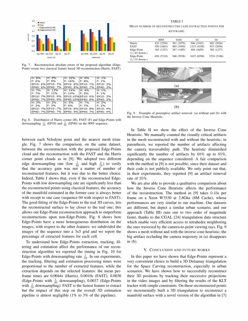
Fig. 7. Reconstruction absolute errors of the proposed algorithm (Edge-Point) versus two classical feature based 3D reconstruction (Harris, FAST).
H: 8%F: 6%EP10: 6%EP40: 6%
H: 9%F: 9%EP10: 7%EP40: 7%
H: 16%F: 16%EP10: 8%EP40: 8%
H: 8%F: 8%EP10: 7%EP40: 7%
H: 1%F: 1%EP10: 3%EP40: 3%
H: 7%F: 7%EP10: 7%EP40: 7%
H: 13%F: 12%EP10: 9%EP40: 9%
H: 14%F: 14%EP10:10%EP40:10%
H: 4%F: 5%EP10: 6%EP40: 6%
H: 1%F: 1%EP10: 3%EP40: 3%
H: 3%F: 3%EP10: 7%EP40: 7%
H: 2%F: 3%EP10: 7%EP40: 7%
H: 5%F: 6%EP10: 8%EP40: 9%
H: 7%F: 7%EP10: 8%EP40: 7%
H: 2%F: 2%EP10: 4%EP40: 4%
Fig. 8. Distribution of Harris corner (H), FAST (F) and Edge-Points withdownsampling 1
10(EP10) and 1
40(EP40) on the 0095 sequence.
between each Velodyne point and the nearest mesh trian-gle. Fig. 7 shows the comparison, on the same dataset,between the reconstruction with the proposed Edge-Pointscloud and the reconstruction with the FAST and the Harriscorner point clouds as in [9]. We adopted two differentedge downsampling rate (low 1
40 and high 110 ) to verify
that the accuracy gain was not a matter of number ofreconstructed features, but it was due to the better choice.Indeed, Table I shows that, even if the reconstructed Edge-Points with low downsampling rate are significantly less thanthe reconstructed points using classical features, the accuracyof the manifold estimated in the former case is always betterwith except to one case (sequence 04 with respect to FAST).The good fitting of the Edge-Points to the real 3D curves, letsthe reconstructed surface to lay closer to the real one; thisallows our Edge-Point reconstruction approach to outperformreconstructions upon non-Edge-Points. Fig. 8 shows howEdge-Points have a more homogeneous distribution on theimages, with respect to the other features: we subdivided theimages of the sequence into a 3x5 grid and we report thepercentage of extracted features for each cell.
To understand how Edge-Points extraction, tracking, fil-tering and estimation affect the performance of our recon-struction algorithm we reported the timing in Fig. 10 forEdge-Points with downsampling rate 1
10 . In our experiments,the tracking, filtering and estimation processing times wereproportional to the number of extracted features, while theextraction depends on the selected features: the mean per-frame times are 0.0044s (Harris), 0.0010s (FAST), 0.0036(Edge-Points with 1
40 downsampling), 0.0037 (Edge-Pointswith 1
10 downsampling). FAST is the fastest feature to extractbut the impact of this step on the overall 3D estimationpipeline is almost negligible (1% to 3% of the pipeline).
TABLE IMEAN NUMBER OF RECONSTRUCTED (AND EXTRACTED) POINTS PER
KEYFRAME.
0095 0104 03 04Harris 423 (2556) 561 (2979) 946 (3342) 692 (2036)FAST 550 (3463) 865 (3950) 1215 (4358) 953 (2850)Edge-Point(1/40 downs.)
165 (1327) 267 (1485) 404 (1650) 382 (1277)
Edge-Point(1/10 downs.)
656 (5310) 946 (5938) 1615 (6598) 1524 (5106)
(a)
(b)Fig. 9. Example of preemptive artifact removal: (a) without and (b) withthe Inverse Cone Heuristic.
In Table II we show the effect of the Inverse ConeHeuristic. We manually counted the visually critical artifactsin the mesh reconstructed with and without the heuristic; inparenthesis, we reported the number of artifacts affectingthe camera traversability path. The heuristic diminishedsignificantly the number of artifacts by 68% up to 85%,depending on the sequence considered. A fair comparisonwith the method in [9] is not possible, since their dataset andtheir code is not publicly available. We only point out that,in their experiments, they reported [9] an artifact removalrate of 35%.
We are also able to provide a qualitative comparison abouthow the Inverse Cone Heuristic affects the performanceof the reconstruction. The method in [9] takes 0.43s perframe on a Xeon W3530 at 2.8Ghz (8M Cache), whoseperformances are very similar to our machine. Our datasetsare different, but depict a similar urban scenario, and ourapproach (Table III) runs one to two order of magnitudefaster, thanks to the CGAL [24] triangulation data structurewhich enable very efficient access to tetrahedra neighboringthe ones traversed by the camera-to-point viewing rays. Fig. 9shows a mesh without and with the inverse cone heuristic; thebig artifact occluding the camera trajectory in (a) disappearsin (b).
V. CONCLUSION AND FUTURE WORKS
In this paper we have shown that Edge-Points represent avery convenient choice to build a 3D Delaunay triangulationfor the Space Carving reconstruction, especially in urbanscenarios. We have shown how to successfully reconstructtheir 3D positions by tracking their successive projectionsin the video images and by filtering the results of the KLTtracker with simple constraints. On these reconstructed pointswe incrementally built a 3D triangulation to reconstruct amanifold surface with a novel version of the algorithm in [7]

Fig. 10. Per-frame time (in seconds) of Edge-Point estimation ( 110
downsampling rate).
TABLE IINUMBER OF ARTIFACTS W/O AND W/ THE INVERSE CONE HEURISTIC.
IN PARENTHESIS NUMBER OF ARTIFACTS AFFECTING THE CAMERA
TRAVERSABILITY PATH.
0095 0104 03 04w/o ICH 21 (4) 21(2) 40(15) 22(7)w/ ICH 4(0) 3(1) 12(3) 7(1)% removed 80(100) 85(50) 70(80) 68(85)
and [9] improved by means of the Inverse Cone Heuristic.The results reached by our algorithm showed that in
urban scenarios the Edge-Points estimation enables a detailedreconstruction, which is better then those obtained by usingonly stable features, such as Harris or FAST corners.
To deal with visual artifacts affecting the reconstructedmanifold, we proposed a very fast method to preemptivelyavoid their creation. In the experiments the manifolds recon-structed with this heuristic are almost clear from visual arti-facts. Future works involve the preemptive filtering of someof the Edge-Points not belonging to the real-world edges orlaying in a very low parallax regions, and the managementof moving 3D points inside the Delaunay triangulation as in[25].
ACKNOWLEDGEMENTS
Work partially funded by the SINOPIAE project, fromthe Italian Ministry of University and Research and RegioneLombardia, and by MEP (Maps for Easy Paths) project fromthe Politecnico di Milano under the POLISOCIAL program.
REFERENCES
[1] M. Pollefeys, D. Nister, J.-M. Frahm, A. Akbarzadeh, P. Mordohai,B. Clipp, C. Engels, D. Gallup, S.-J. Kim, P. Merrell, et al., “Detailedreal-time urban 3d reconstruction from video,” International Journalof Computer Vision, vol. 78, no. 2-3, pp. 143–167, 2008.
[2] C. Hane, C. Zach, A. Cohen, R. Angst, and M. Pollefeys, “Joint 3dscene reconstruction and class segmentation,” in Computer Vision andPattern Recognition (CVPR), 2013 IEEE Conference on. IEEE, 2013,pp. 97–104.
[3] N. Cornelis, B. Leibe, K. Cornelis, and L. Van Gool, “3d urban scenemodeling integrating recognition and reconstruction,” InternationalJournal of Computer Vision, vol. 78, no. 2-3, pp. 121–141, 2008.
[4] S. M. Seitz, B. Curless, J. Diebel, D. Scharstein, and R. Szeliski,“A comparison and evaluation of multi-view stereo reconstructionalgorithms,” in Computer vision and pattern recognition, 2006 IEEEComputer Society Conference on, vol. 1. IEEE, 2006, pp. 519–528.
[5] N. Snavely, S. M. Seitz, and R. Szeliski, “Photo tourism: exploringphoto collections in 3d,” ACM transactions on graphics (TOG),vol. 25, no. 3, pp. 835–846, 2006.
[6] Q. Pan, G. Reitmayr, and T. Drummond, “Proforma: Probabilisticfeature-based on-line rapid model acquisition.” in BMVC, 2009, pp.1–11.
TABLE IIIPER-FRAME TIME (IN SECONDS) OF THE INVERSE CONE HEURISTIC
(ICH) FOR PREEMPTIVE ARTIFACTS REMOVAL.
0095 0104 03 040.002 0.003 0.010 0.001
[7] V. Litvinov and M. Lhuillier, “Incremental solid modeling from sparseand omnidirectional structure-from-motion data,” 2013.
[8] D. I. Lovi, N. Birkbeck, D. Cobzas, and M. Jagersand, “Incre-mental free-space carving for real-time 3d reconstruction,” in FifthInternational Symposium on 3D Data Processing Visualization andTransmission(3DPVT), 2010.
[9] V. Litvinov and M. Lhuillier, “Incremental solid modeling from sparsestructure-from-motion data with improved visual artifacts removal,” inInternational Conference on Pattern Recognition (ICPR), 2014.
[10] M. Meyer, M. Desbrun, P. Schroder, and A. H. Barr, “Discretedifferential-geometry operators for triangulated 2-manifolds,” in Vi-sualization and mathematics III. Springer, 2003, pp. 35–57.
[11] H.-H. Vu, P. Labatut, J.-P. Pons, and R. Keriven, “High accuracyand visibility-consistent dense multiview stereo,” Pattern Analysis andMachine Intelligence, IEEE Transactions on, vol. 34, no. 5, pp. 889–901, 2012.
[12] A. Delaunoy, E. Prados, P. Gargallo I Piraces, J.-P. Pons, and P. Sturm,“Minimizing the multi-view stereo reprojection error for triangularsurface meshes,” in BMVC 2008-British Machine Vision Conference.BMVA, 2008, pp. 1–10.
[13] S. Rhein, G. Lu, S. Sorensen, A. R. Mahoney, H. Eicken, G. C.Ray, and C. Kambhamettu, “Iterative reconstruction of large scenesusing heterogeneous feature tracking,” in Computer Vision and PatternRecognition Workshops (CVPRW), 2013 IEEE Conference on. IEEE,2013, pp. 407–412.
[14] M. Tomono, “Detailed 3d mapping based on image edge-point icp andrecovery from registration failure,” in Intelligent Robots and Systems,2009. IROS 2009. IEEE/RSJ International Conference on. IEEE,2009, pp. 1164–1169.
[15] B. D. Lucas and T. Kanade, “An iterative image registration techniquewith an application to stereo vision.” in IJCAI, vol. 81, 1981, pp.674–679.
[16] D. A. Cucci and M. Matteucci, “Position tracking and sensors self-calibration in autonomous mobile robots by gauss-newton optimiza-tion,” in Robotics and Automation (ICRA), 2014 IEEE InternationalConference on. IEEE, 2014, pp. 1269–1275.
[17] A. Geiger, P. Lenz, and R. Urtasun, “Are we ready for autonomousdriving? the kitti vision benchmark suite,” in Computer Vision andPattern Recognition (CVPR), 2012 IEEE Conference on. IEEE, 2012,pp. 3354–3361.
[18] M. Lhuillier and S. Yu, “Manifold surface reconstruction of an en-vironment from sparse structure-from-motion data,” Computer Visionand Image Understanding, vol. 117, no. 11, pp. 1628–1644, 2013.
[19] P. Labatut, J.-P. Pons, and R. Keriven, “Efficient multi-view reconstruc-tion of large-scale scenes using interest points, delaunay triangulationand graph cuts,” in Computer Vision, 2007. ICCV 2007. IEEE 11thInternational Conference on. IEEE, 2007, pp. 1–8.
[20] R. Hartley and A. Zisserman, Multiple view geometry in computervision. Cambridge Univ Press, 2000, vol. 2.
[21] S. Yu and M. Lhuillier, “Incremental reconstruction of manifoldsurface from sparse visual mapping,” in 3D Imaging, Modeling,Processing, Visualization and Transmission (3DIMPVT), 2012 SecondInternational Conference on. IEEE, 2012, pp. 293–300.
[22] R. I. Hartley and P. Sturm, “Triangulation,” Computer vision and imageunderstanding, vol. 68, no. 2, pp. 146–157, 1997.
[23] D. Girardeau-Montaut, “Cloud compare, (last access feb, 27 2015).”[Online]. Available: http://www.cloudcompare.org/
[24] The CGAL Project, CGAL User and Reference Manual, 4.5 ed.CGAL Editorial Board, 2014. [Online]. Available: http://doc.cgal.org/4.5/Manual/packages.html
[25] A. Romanoni and M. Matteucci, “Efficient moving point handlingfor incremental 3d manifold reconstruction,” in Image Analysis andProcessing ICIAP 2015. Springer, 2015, pp. 489–499.