increase of electrospray throughput using multiplexed ... deng jaerosol microcombustor.pdf · 698...
TRANSCRIPT

Aerosol Science 37 (2006) 696–714www.elsevier.com/locate/jaerosci
Increase of electrospray throughput using multiplexedmicrofabricated sources for the scalable generation of
monodisperse droplets
Weiwei Denga, James F. Klemicb, Xiaohui Lib, Mark A. Reedb, Alessandro Gomeza,∗aDepartment of Mechanical Engineering, Yale University, New Haven, CT 06520-8286, USAbDepartment of Electrical Engineering, Yale University, New Haven, CT 06520-8284, USA
Received 13 April 2005; received in revised form 1 May 2005; accepted 16 May 2005
Abstract
The development, fabrication, and testing of a compact multiplexed system of electrosprays are presented withthe dual goal of increasing by orders of magnitude the liquid flow rate to be dispersed and of retaining the quasi-monodispersity of the generated droplets. The system was microfabricated as an array of nozzles etched in silicon,with a density of 250 sources/cm2. Although the operation of a single electrospray is rather forgiving with respectto the electrode geometry, successful performance of the multiplexed system is critically dependent on a carefulselection of the electrode configuration, which in the present work entails an extractor electrode mounted at adistance from the spray sources that is comparable to the distance between sources (on the order of 0.5 mm). Theelectrode has the dual function of limiting electric field cross-talk between neighboring sources and minimizingspace charge feedback from the spray cloud. Measurements of current and droplet size as a function of flow rateand of droplet size distribution using ethanol demonstrated that the system may be optimized to produce uniformdroplets simultaneously from all parallelized electrosprays, each one operating as an isolated spray in the quasi-monodisperse cone-jet mode. Ease of operation and uniformity in size from spray to spray require strategies toincrease the pressure drop in the liquid flow path and/or to uniformize the electric field at the spray sources.� 2005 Elsevier Ltd. All rights reserved.
Keywords: Electrospray; Multiplexing; Microfabrication; Monodisperse droplets; MEMS; Microfluidics
∗ Corresponding author. Tel.: +1 203 432 4384; fax: +1 203 432 7554.E-mail address: [email protected] (A. Gomez).
0021-8502/$ - see front matter � 2005 Elsevier Ltd. All rights reserved.doi:10.1016/j.jaerosci.2005.05.011

W. Deng et al. / Aerosol Science 37 (2006) 696–714 697
1. Introduction
A primary goal of fine particle synthesis is the ability to generate particles with narrow size distributionsat flow rates adequate for various applications. This statement holds regardless of applications, from drugdelivery, to the synthesis of nanoparticle ceramics, superconductors, quantum dots, photonic crystals andthin films. If one can tailor the size for a particular effect, for example, for the controlled/targeted drugrelease or to generate quantum dots with peculiar properties, the impact of fine particle synthesis will bedramatic. The present study focuses on the electrospray in the so-called cone-jet mode, a device that canproduce monodisperse droplets/particles over a wide size range, from a few nanometers to hundreds ofmicrometers, depending on liquid flow rate, applied voltage and liquid electric conductivity. In particular,in the nanometric scale range, the capability of producing monodisperse particles with relative ease isunmatched by any other aerosol generation scheme. Our long-term goal is to remedy the main drawbackthat has hampered to date its widespread use in nanoparticle synthesis: low throughput.
Electrostatic means for liquid dispersion in minute droplets are used in a variety of technologicalapplications (Bailey, 1988). In some systems, electric forces exclusively drive liquid dispersion, so thatatomization and gas flow processes are relatively uncoupled. Such systems are referred to as electrosprays(ES). Within the electrospray class of atomizers is a particular type characterized by the additional featureof a tight control of the size distribution of the resulting aerosol. Such a system can be implemented byfeeding a liquid with sufficient electric conductivity through a small opening, such as the tip of a capillarytube or a suitably treated “hole”, maintained at several kilovolts relative to a ground electrode positionedat an appropriate distance from it. The liquid meniscus at the outlet of the capillary takes a conical shapeunder the action of the electric field, with a thin jet emerging from the cone tip. This jet breaks up furtherdownstream into a spray of fine, charged droplets. Because of the morphology of the liquid meniscus,this regime is labeled as the cone-jet mode (Cloupeau & Prunet-Foch, 1989). Among the key featuresdistinguishing the cone-jet electrospray from other atomization techniques are quasi-monodispersity ofthe droplets; Coulombic repulsion of the charged droplets, which induces spray self-dispersion, preventsdroplet coalescence and enhances mixing with a secondary stream; and the use of a spray “nozzle”with a relatively large bore with respect to the size of the generated droplets, minimizing the liquid lineobstruction risks.
Electrospray ionization mass spectrometry (ESI-MS), spearheaded by the pioneering work of Fenn atYale in the 1980s (Fenn et al., 1989), is the only practical application of the electrospray in widespreaduse, as recognized by his 2002 Chemistry Nobel Prize. Key drawbacks that have hampered applications toother aerosol areas are, first and foremost, the low flow rates at which the cone-jet mode can be establishedand, to a lesser extent, the restrictions on the liquid physical properties of the liquids that can be dispersedwith this technique. If such drawbacks are addressed and eliminated, the electrospray may find evengreater use in a wide variety of applications, well beyond mass spectrometry.
Low flow rates represent a particularly severe drawback for applications requiring that the initialdroplet size be small, as, for example, in drug inhalation or nanoparticle synthesis, which are areas ofintense aerosol research. Since the electrospray exhibits a monotonic dependence of droplet size onflow rate (Chen et al., 1997; Tang & Gomez, 1995, 1996), if small droplets are needed to generatenanoparticles, mass flow rate may be minuscule (Gomez et al., 1997). The smaller the desired parti-cle size, the smaller the mass flow rate. To provide quantities of nanoparticles suitable for biologicaltests, pharmaceutical treatment or other high-value-added applications, multiplexing the spray source isnecessary.

698 W. Deng et al. / Aerosol Science 37 (2006) 696–714
The second drawback limits the applications to particle “precursors” that are well suited to dissolutionin conducting fluids. If the goal is to generate very small droplets and ultimately nanoparticles, theconductivity of the working fluids may have to be relatively large, which may conflict with other constraints(e.g., pH-neutral solution in biomedical applications). Furthermore, in some applications organic and non-conductive buffers may be preferable, in which case the cone-jet electrospray would not be viable sinceits charging mechanism is inductive and requires a finite electric conductivity in the working fluid.
These two drawbacks have relegated the electrospray to the realm of academic curiosity, with the no-table exception of mass spectrometry applications. Attempts to remedy the second shortcoming consistin having the working fluid with unsuitable properties “dragged” by an outer fluid with acceptable elec-trospray behavior in a two-fluid system (Loscertales et al., 2002; Smith, Barinaga, & Udseth, 1988). Withrespect to the flow rate limitations, the total flow rate to be dispersed in small droplets can be increasedby multiplexing. This approach has been investigated with conventional machining to a limited degree(Almekinders & Jones, 1999; Kyritsis et al., 2002; Rulison & Flagan, 1993), in some cases without pre-serving monodispersity (Almekinders & Jones, 1999). It may also be impractical by more than one ortwo orders of magnitude, at least for typical configurations involving capillaries, nozzles or typical pro-trusions on which sprays are anchored. Further, the form factor of conventionally machined multiplexedsystems limits practical scaling to relatively small amounts. A modestly multiplexed (by a factor of 9),but quite compact, system was developed by laser etching (Tang et al., 2001), with the goal of improvingmass-spectrometry sensitivity in electrospray applications, rather than increasing the dispersed flow rates.
The task of dramatically increasing the throughput of electrospray systems, without sacrificing dropletmonodispersity, may be addressed using microlithographic fabrication techniques developed for the fieldof MEMS (micro-electro mechanical systems) (Elwenspoek & Jansen, 1999; Madou, 1997). Namely, byadapting conventional silicon integrated circuit fabrication technology to the machining of mechanicalstructures in silicon and other materials, there is an opportunity of multiplexing electrospray devicesat unparalleled scales, that is, by several orders of magnitude. Efforts using clean room technology inmicrofabricated electrospray systems have been previously pursued in mass spectrometry (Zhang et al.,2003), but also in that case the goal was to analyze a large batch of samples, one at a time, in an automaticway, rather than operating all of them in parallel. The dual goal of the present study is to increase byorders of magnitude the liquid flow rate to be dispersed and to retain the quasi-monodispersity of thegenerated droplets. Contrary to the operation of a single electrospray that is rather forgiving with respectto the electrode geometry, successful performance of the multiplexed system will be shown to be criticallydependent on a careful selection of the electrode configuration. Measurements of spray current and dropletsize distribution will be used to characterize the system aerosol performance.
2. Experimental approach
Multiplexed electrospray distributors were microfabricated in silicon using deep reactive ion etch(DRIE) of silicon wafers. Uniform nozzles, interspaced at various distances (2.52, 1.26 and 0.675 mm),and protruding from 150 to 450 �m were patterned with outer diameters ranging from 180 to 240 �m,and a fixed inner diameter of 120 �m. Fig. 1 sketches the specific microfabrication process flow usedto fabricate the tested devices. Using double-sided wafer processing and deep reactive ion etching, apolished Si wafer with an oxide mask layer is patterned on both sides to realize nozzle arrays. DRIEof silicon can yield essentially straight sidewalls with large aspect ratios. Minimum feature sizes can be

W. Deng et al. / Aerosol Science 37 (2006) 696–714 699
Fig. 1. Microfabrication process flow used to fabricate the tested devices.
Fig. 2. Typical 91-nozzle system, with scanning electron micrographs of the nozzle array and of an individual nozzle.
on the order of 1 �m, which guarantees virtually identical protrusions, all acting as pseudo-capillaries.Fig. 2 shows scanning electron micrographs (SEMs) of a typical configuration, in this case a 91-nozzlehexagonally patterned arrangement. Excellent pattern transfer is evident on the individual nozzle SEM,with nearly vertical sidewalls in both the nozzle interior and exterior. The process allows for easy variation(e.g., nozzle scaling and array design) to optimize the intended application. Under certain conditions thereproducibility of geometric features between protrusions is an important prerequisite to equidistributionof flow rates among the multiplexed nozzles, and to the establishment of a controlled electric field at eachnozzle, as will be discussed below.
A typical testing arrangement requires mounting the microfabricated distributor on a liquid reservoir,positioning suitable additional electrodes, and providing an electric connection to maintain the desiredvoltage drop between the distributor and the other electrodes. Details on the electrode configuration willbe discussed in the following section. For all of the experiments discussed, we operated a multiplexedsystem of approximately 250 nozzles/cm2, although higher and lower density multiplexed systems maybe readily microfabricated in the same manner.

700 W. Deng et al. / Aerosol Science 37 (2006) 696–714
The current was measured by connecting the virtual ground to a voltmeter with known input impedance.Visual observation of the mode of operation was made possible by a laser beam focused by two lensesinto a sheet parallel to the distributor surface and positioned a few millimeters downstream of the cone-jets. Scattering of the charged droplets in each spray resulted in the visualization of individual spraycross-sections appearing as small circular spots.
Tests were performed using ethanol, an alcohol with good electrospraying properties. The liquid waspumped continuously into the reservoir using a syringe pump with different syringe sizes to ensure thatthe plunger would be displaced at a reproducible and accurate speed.At the low flow rates, small (0.25 and1 ml) syringes were used; the smaller the diameter of the syringe, the more accurate and steady the motionof the syringe plunger. As a result, the measurement of the current was more accurate and the range ofstable flow rates for a given mode was increased. The liquid was sonicated for a few minutes prior to beingloaded in the syringe slowly and steadily, to minimize the formation of microbubbles. Subsequently, theloaded syringe was sonicated for a few minutes to further eliminate possible microbubbles.
Droplet sizes were measured by a phase Doppler anemometer (Dantec, Electronik) capable of measur-ing simultaneously droplet size and two velocity components from the scattering of a frequency-modulatedargon ion laser beam (Spectra Physics). The electrospray set-up was mounted on a multi-direction trans-lational stage allowing for the systematic scanning of the spray by the laser probe volume. This volumewas imaged on the receiver optics, which was coupled to photomultipliers for the signal recording andsubsequent processing. A dedicated electronic processor sampled and analyzed the signal using DantecBSA Flow Software. For each measurement, 5000 counts per sample were taken. Measurements wereperformed at a given flow rate by selecting the applied voltage so that the size distribution histogramwould be as monodisperse as possible. In the cone-jet mode, although the bulk of the flow rate is dis-persed in uniform size droplets, a small percentage may be dispersed as much smaller satellites thatare electrostatically and inertially confined to the periphery of the spray (Tang & Gomez, 1994). To en-sure that primary droplets were sized up, the laser probe volume was positioned along the axis of eachspray.
3. Design criterion
A successful design should ensure that all nozzles operate simultaneously for a broad range of flowrates, with uniform droplet size from nozzle to nozzle, in a compact multiplexed system. In view ofthe monotonic dependence of droplet size on flow rate (Chen et al. 1997; Tang & Gomez, 1995, 1996),once the cone-jet regime is established, uniformity of droplet size for all nozzles imposes uniformityof flow rates. Fine tuning conditions in each nozzle, with independent control of flow rate and electricconditions, would pose prohibitive fabrication and operational challenges. An optimal design shouldensure fabrication simplicity and nearly identical conditions for all nozzles.
A criterion can be formalized as follows. Consider the system illustrated in Fig. 3, highlighting acommon feed tube, a reservoir with an optional flow homogenizer, the parallel nozzles and the cone-jetliquid/air interface. If we apply a momentum balance to the generic control volume CVi , under steadystate conditions and with negligible body forces, we obtain∫
CSi
�v��v · d �A =∑ �FSi
,

W. Deng et al. / Aerosol Science 37 (2006) 696–714 701
Common feed tube
Si nozzles
Channel i Channel j
Liquid
3
2
1
2
3
1Reservior
“homogenizer”
Control volume i Control volume j
Fig. 3. System schematic with fluid control volume.
where the term on the right-hand side combines all surface forces acting on the control surface CSi
bounding CVi . If each parallel channel is to have the same flow rate, the inertia term on the left-handside of the equation must be the same, regardless of the channel. The equidistribution of flow rates thenimplies that for the generic channels i and j∑ �FSi
=∑ �FSj
=∑ �FS = �FS1 + �FS2 + �FS3 ,
where subscript i and j can be dropped, and the last equality refers to the decomposition of the totalsurface forces in each channel into three contributions: �FS1 , �FS2 and �FS3 , referring to the homogenizerregion, the nozzle and the cone-jet interface, respectively. In region 1, only pressure and viscous forcesare at play with the establishment of a pressure drop to overcome viscous losses. In region 2, similarconsiderations apply, with the establishment of the well-known Hagen–Poiseille flow at the prevailingReynolds numbers of unity order. In region 3, capillary forces and electrohydrodynamic normal andshear stresses at the liquid/air interface are important and would need to be integrated on the liquid/airinterface. Capillary forces depend on the liquid surface tension and on the interface geometry. Electro-hydrodynamic stresses depend on the electric field at the nozzle outlet. Implicit in this argument is thatthe electric charge has relaxed to the fluid/air interface, as typical of the stable cone-jet electrosprayregime.
In region 1, uniformity of the pressure drop across the homogenizer would be required with the insertionof baffles, honeycombs, beads, frits and other obstructions that would ensure that there are no preferentialpaths from the feed tube outlet to each nozzle. However, if �FS2? �FS3 , there would not even be need for ahomogenizer since the prevailing Reynolds number in the fluid reservoir is of order 10−2 and one wouldexpect a uniform Stokes regime, with no separation at the walls and �FS1 ≈ 0. The condition �FS2? �FS3
can be reached by judicious selection of the inner diameter of the parallel nozzles and flow uniformityfrom nozzle to nozzle would be guaranteed by the high spatial resolution of microfabrication. With either

702 W. Deng et al. / Aerosol Science 37 (2006) 696–714
�FS1 or �FS2 or both much larger than �FS3 , the system should be relatively uninfluenced by edge effects inthe electric field distribution affecting �FS3 (see Fig. 5) and the requirement on the electric field is that itbe sufficiently intense for the cone-jet to be established at each nozzle.
If neither of the conditions above is fulfilled, the following situation ensues. For a given interfacegeometry and liquid surface tension, capillary forces are fixed. Particularly important now become theelectrohydrodynamic stresses that extrude the fluid into a ligament that is orders of magnitude smallerthan the nozzle bore. In such a case, great care must be taken to ensure that the electric field does not varysignificantly from nozzle to nozzle, since this field controls not only the establishment of the cone-jetregime, but also the liquid flow rate that is drawn from each nozzle.
To establish an intense electric field, the simplest configuration would entail mounting a flat electrodeat a distance from the multiplexed distributor. The distance selection is critical, since a few characteristiclength scales are already apparent in the distributor design: the inter-nozzle distance, lin, the nozzleprotrusion, h, and the nozzle diameter, D. Microfabrication allows for the manufacturing of essentiallyplanar structures, with protrusions limited by the wafer thickness. In the present system, h was limited to0.45 mm, which for the densest packing is of the same order as the inter-nozzle distance, lin, at 0.675 mm.If the flat electrode is mounted at a distance L?h, the effect of the protrusion would be irrelevant and theelectric field established would essentially be that which is between two capacitor plates. It is doubtfulthat with such a configuration sufficiently intense electric fields can be established for the cone-jet modeof operation, before the onset of corona breakdown in the surrounding gas. Furthermore, feedback fromspace charge may become inevitable.
If, on the other hand, L ∼ h>lin, the effect of the protrusions will be significant and the field canbe localized with minimal influence of the neighboring nozzles. Inevitable flooding of the liquid flow-ing through the system would prevent operation with a ground electrode a fraction of a millimeteraway from the nozzle. If a ring electrode to let the fluid through a small opening is used, the cone-jetcan be established and a spray with the appropriate properties for a given application can be formed.This configuration, often called “extractor electrode”, is typically used in electron beam applications.It was also used in early electrospray applications to electric propulsion (e.g., Hendricks, 1962) andcombustion (e.g., Chen & Gomez, 1996). The generated droplets would eventually reverse their pathsand be attracted back to the lower potential electrode, causing flooding and eventual interruption ofthe flow. This effect can be avoided if an additional electrode is put in place at an even lower poten-tial to “sweep” the droplets away and use them for the intended applications. This can be combinedalso with an external flow that would drag the droplet away overcoming electrostatic attractive forces.The additional advantage of this configuration is that it shields the cone-jet region at the source of thespray from the region where the spray cloud disperses, with attending space charge. A separation ofthe cone-jet region from the spray utilization region is generally desirable for stability and applicationconsiderations.
The chosen electrode configuration is depicted in the schematic in Fig. 4(a). The microfabricated Sidistributor is charged at about 1 kV potential above that of a metal ring extractor plate positioned ata distance of typically 200–500 �m by means of a glass insulator spacer, under conditions in whichL < h < lin. Since L is only a factor of 3 smaller than lin, it is likely that nozzle cross-talk may notbe completely eliminated. The stainless steel ring extractor itself was designed and microfabricatedusing photolithography and metal etching to tolerances compatible with the microfabricated nozzle array.Visible in the schematic is a ground electrode several millimeters downstream. Comments on the othertwo configurations in Fig. 4 will be made in the discussion of Fig. 5 below.

W. Deng et al. / Aerosol Science 37 (2006) 696–714 703
Fig. 4. Schematic of various electrode configurations.
0.0 0.5 1.0 1.5 2.0 2.5
2000
4000
6000
8000
10000
12000
Nor
m e
lect
ric fi
eld
(V/m
m)
X (mm)
V=1 kV (Ring extractor) V=28 kV (Planar ground) V= 8 kV (Hemispherical ground)
Fig. 5. Comparison of the electric field at the outer nozzle and at the central one in a system of seven nozzles for the threeelectrode geometries in Fig. 4.
4. Results and discussion
4.1. Electrostatics modeling of various configurations
Modeling of the external electric field using FEMLAB (COMSOL Inc., 2005) provided supportingevidence of the electric field design criterion. We underline the qualitative nature of these calculations,since the presence of the liquid and its coupling with the electric field are unaccounted for and poses amuch more challenging problem. Even if the governing equations and boundary conditions were prop-erly specified in the full electrohydrodynamic problem, the disparity of length scales would dictate avery challenging computational approach, since these devices span four orders of magnitude from themicrometer size liquid-drop ligament at the breakup point (the critical region where electrospray forms)to the several millimeters of the overall device domain size. The difficulties would be compounded further

704 W. Deng et al. / Aerosol Science 37 (2006) 696–714
by the need to capture the transient behavior of the system, with the instabilities that limit its behavior,and the presence of moving boundaries at the fluid/gas interface.
Simple electrostatic modeling is revealing in explaining some of the experimental observations. To thatend, solutions of the Laplace equation ��=0 for the electric potential � were computed using FEMLABfor a simplified geometry consisting of seven nozzles protruding from a distributor plate. The electric fieldwas computed by post-processing the potential field. Computations were performed for three cases: theextractor electrode that was described in detail in the preceding discussion (Fig. 4a); simple flat electrodeat a working distance of 1 cm from the wafer, as a reference case (Fig. 4b); and a ground electrode shapedas a paraboloid to decrease the distance between the innermost nozzles and the ground, as compared tothat of the outermost nozzles (Fig. 4c), for reasons to be discussed below. The voltage levels in the threecases were chosen so that the electric fields at the nozzles would be comparable in the three cases. In thesecond case the wafer was charged at 28 kV with respect to a flat ground electrode 1 cm away; in the thirdone, it was charged at 8 kV with respect to a hemispherical ground electrode, the bottom of which was3 mm away from the wafer. Fig. 5 shows the electric field at the three nozzles where the cone-jet wouldbe formed.
Notice that to achieve approximately the same field, one needs extremely high voltages in the secondcase (Fig. 4). In a typical startup procedure in such a configuration, the outer nozzles in the array wouldelectrospray first, as a consequence of the more intense field locally (see below), whereas the innermostnozzles would fail to operate leading to flooding of the distributor with the formation of a liquid layer thatcould not be disrupted into controlled and properly anchored electrosprays. Increasing the voltage to theextremely high values used in the calculations would not be practical. Sharp corners in contact with thecharged electrode, contact wires, or even surface irregularities resulting from microfabrication can causecorona discharge in the surrounding gas. This configuration failed to work in preliminary attempts. In thethird case (Fig. 4c), in which the ground electrode was properly shaped to enhance the homogeneity inelectric field among the nozzles and reduce the applied potential to approximately 8 kV, we managed toget all sprays to “fire” at the same time. With the ring extractor and the paraboloid ground configurationsthe degree of nonuniformity in the field between the side nozzles and the central one is reduced from22% in the case of the flat electrode (Fig. 4b) to approximately 10%, which may explain why theseconfigurations were successful. However, the paraboloid geometry proved impractical since operationcould be established for brief periods of time before electrode flooding would ensue. Furthermore, thegeometry of the ground electrode may have to be tailored to a particular liquid flow rate and liquidconductivity, since both variables may affect the space charge field.
The electric field comparison in Fig. 5 suggested that the ring extractor configuration, is the mostpromising; consequently, it was used in all subsequent tests. Fig. 6 shows pictures of the microfabricateddistributor, with the customary penny as size standard, and of the system in operation with a multitudeof sprays issuing from the system.
4.2. �FS1 ≈ 0, �FS2 comparable to �FS3: critical role of the external electric field
Let us consider the limiting case, �FS1 ≈ 0, in which there is no homogenizer and the pressure dropin the nozzles does not overwhelm interfacial forces. As discussed earlier, electrohydrodynamic stressesthat depend on the electric field at the nozzle are particularly important in this case since this field controlsnot only the establishment of the cone-jet regime, but also the liquid flow rate that is drawn from eachnozzle. The electric field is due to the electric potential applied between electrodes, the so-called external

W. Deng et al. / Aerosol Science 37 (2006) 696–714 705
Fig. 6. (a) Microfabricated distributor, with the penny as size standard, and (b) system in operation with a multitude of sprays.
1 2 3 4 5 6 70
2
4
6
8
10
1 2 3 4 5 6 7Dro
plet
siz
e (m
icro
n)
Nozzle number
Fig. 7. Average droplet diameter in individual cone-jet electrosprays in the multiplexed mode.
field, and can be mitigated by the space charge field that is due to the charged droplet cloud downstream,if the extractor electrode is inadequate to shield the cone-jet from the cloud (Tang & Gomez, 1994). Inthe present experiments characterized by liquids of relatively modest conductivity, space charge does notappear to be an issue. Its feedback may become non-negligible as the current through the system increasesand at some point it may even hinder the system operation.
As long as the external electric field is the same at each nozzle, the goal of uniform flow rates anddroplet size can be achieved. However, the calculations discussed in Fig. 5 already show that edge effectsmay be inevitable, with the electrostatic pull in the outermost array of nozzles being stronger, whichshould result in larger flow rates and droplet size. We will now see indirect experimental confirmationof this nonuniformity. To ease the monitoring of the system, we cut the outermost nozzles to leave anhexagonal pattern of 37 nozzles. Fig. 7 shows the droplet average diameter measured in a scan across thehexagon with nozzle numbers identified in the inset in the figure. As anticipated, the outermost nozzlespass a higher flow rate and generate larger droplets, which is entirely consistent with the external fieldelectrostatic pattern in Fig. 5.
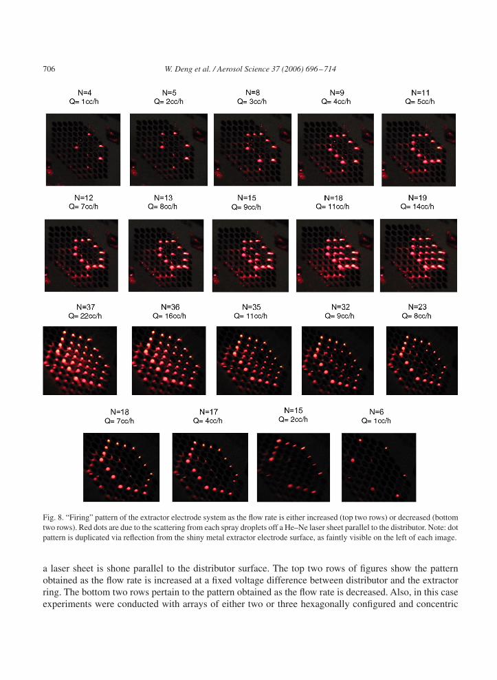
Further evidence of the importance of the external field uniformity is provided by the “firing” patternof the multiplexed system as the flow rate is increased. Fig. 8 shows the scattering pattern observed as
706 W. Deng et al. / Aerosol Science 37 (2006) 696–714
Fig. 8. “Firing” pattern of the extractor electrode system as the flow rate is either increased (top two rows) or decreased (bottomtwo rows). Red dots are due to the scattering from each spray droplets off a He–Ne laser sheet parallel to the distributor. Note: dotpattern is duplicated via reflection from the shiny metal extractor electrode surface, as faintly visible on the left of each image.
a laser sheet is shone parallel to the distributor surface. The top two rows of figures show the patternobtained as the flow rate is increased at a fixed voltage difference between distributor and the extractorring. The bottom two rows pertain to the pattern obtained as the flow rate is decreased. Also, in this caseexperiments were conducted with arrays of either two or three hexagonally configured and concentric

W. Deng et al. / Aerosol Science 37 (2006) 696–714 707
0 2 4 6 8 10 12 14 160
2
4
6
8
10
12
14
16
18
20
Num
ber
of s
pray
s
Flow rate (cc/h)
Number of sprays as flow rate increases Number of sprays as flow rate decreases
Fig. 9. Hysteresis in the “firing” pattern as the liquid flow rate is first increased and then decreased.
nozzles, obtained from the initial distributor by selectively cutting the outermost nozzles. Note that thepattern in each figure is mirrored by the reflection on the shiny metal extractor electrode surface on theleft of each image. It is observed that, as a function of flow rate, the outermost nozzles at the vertices ofthe hexagon begin to fire first (top left). As the flow rate is increased, the other nozzles in the outermost“ring” gradually turned on. Next, the central nozzle begins to fire and finally the intermediate “ring” isturned on, until all 19 nozzles are “firing” at the same time. Most interesting is the hysteretic pattern withrespect to the number of jets that are simultaneously operating, which is a function of whether a particularflow rate is achieved by decreasing or increasing the liquid pumped through the system. As shown inFig. 9 for the system of 19 electrosprays, there is a monotonic dependence of number of jets operating onflow rate as the flow rate is increased. Once all jets have been turned on, the flow rate can be decreased bymore than a factor of two before any electrospray disappears. In other words, the average flow rate neededto generate a new spray at a nozzle is higher than the average flow rate to keep a spray. Furthermore,when a mechanical and/or electrical perturbation is introduced (e.g., by tapping the fluid reservoir, orintroducing a metal tip in the vicinity of non-operating nozzles), more cone-jets can be turned on (ascompared to the data in Fig. 9).
Fig. 10 shows details of the electric field computed on each of the nozzles in the 19-nozzle hexagonalpattern, with numbering of different profiles in correspondence of different nozzle types (e.g., at a vertexof the hexagon, at the center, etc.). Somewhat surprisingly, the “firing” pattern in Fig. 8 (top row) forincreasing flow rate is entirely consistent with the hierarchy of intensity of electric field at the nozzleoutlets. This observation suggests that, first, space charge is not controlling the system performance, asintended by the selection of the extractor electrode design. Second, it shows that details of the cone-jetmorphology and of the potential drop through the quasi-equipotential liquid are not critical. If this is thecase, further fine-tuning of the microfabrication design, which may be planned in the future by simplyusing FEMLAB and solving Laplace equation for different geometries, can yield greater uniformity inboth firing pattern and droplet size.
We also notice that the greatest nonuniformity in the field is between the outermost “ring” and therest of the nozzles. If such nozzles are plugged, greater droplet uniformity would ensue at the cost ofsacrificing some of the microfabricated nozzles. Fig. 11 demonstrates this feature for a system of 61

708 W. Deng et al. / Aerosol Science 37 (2006) 696–714
0.0 0.1 0.2 0.3 0.4 0.5 0.6 0.7 0.80
2000
4000
6000
8000
10000
12000
14000
16000
18000
Ele
ctric
Fie
ld (
V/m
m)
x (mm)
Nozzle 1 Nozzle 2 Nozzle 3 Nozzle 4
2 3 4 1
Fig. 10. Details of the electric field computed on each of the nozzles in a 19-nozzle hexagonal pattern. Numbering correspondsto different positions of the nozzles, as shown in the inset.
1 2 3 4 5 6 7
1 2 3 4 5 6 70
2
4
6
8
10
12
14
16
Dro
plet
siz
e (m
icro
n)
Jet number
Q=0.4cc/h Q=0.5cc/h Q=0.6cc/h
Fig. 11. Average droplet diameter in individual cone-jet electrosprays in the multiplexed mode with the outer “ring” of plugged“dummy” nozzles.
nozzles, the outer ring of which consisted of 24 plugged nozzles, leaving the remaining 37 in operation.To quantify the size scatter from jet to jet, a relative standard deviation (RSD) for the average droplet sizeof all operating sprays is defined as
RSD = 1
D̄
√√√√ N∑i=1
(D̄i − D̄)2
/(n − 1),
where D̄i is the average droplet diameter for jet i, and D̄ = ∑D̄i/n is the droplet size averaged over
all jets. The uniformity of the droplet size is good, with the RSD < 0.053, which is comparable to the

W. Deng et al. / Aerosol Science 37 (2006) 696–714 709
Table 1Average droplet size and relative standard deviation (RSD) for the conditions of Fig. 11
Nozzle number d̄(�m) RSD
Q̇ = 0.4 cc/h, D̄ = 9.16 �m1 9.56 0.072 9.52 0.083 9 0.084 9.3 0.095 8.82 0.096 8.52 0.107 9.38 0.09
Q̇ = 0.5 cc/h, D̄ = 10.22 �m1 11.15 0.082 10.47 0.083 9.85 0.094 10.21 0.105 9.91 0.106 9.5 0.087 10.47 0.09
Q̇ = 0.6 cc/h, D̄ = 11.12 �m1 12.06 0.082 11.45 0.093 10.73 0.094 11.1 0.105 10.74 0.116 10.3 0.097 11.49 0.09
degree of non-uniformity in size within a single jet, as measured by an RSD of 0.09, attesting to thequasi-monodispersity requirement. Table 1 provides further details. Notice that even the small changesin droplet size from nozzle to nozzle seem to be consistent with the hierarchy of electric field intensity inFig. 10, with a relative maximum in correspondence of the central nozzle.
4.3. Current measurements
To characterize the multiplexed system quantitatively, under the same conditions as in the precedingsection and with the outermost nozzles plugged, we related the behavior of the multi-jet regime to thebetter-known single electrospray cone-jet mode. To that end, the average current per jet was compared tothat measured in a separate experiment in which all protrusions but one were cut off and the correspondingholes plugged, to generate a single cone-jet regime. With the electrospray in the multiplexed regime, thetotal current was measured and the number of jets was counted, with the ratio of the values yielding theaverage current per jet. Results are plotted in Fig. 12. Although considerable work has been made inderiving scaling laws for different liquids that are largely based on dimensional analysis, in the presentcase we will refrain from applying such laws since no comparisons with other fluids will be made. Thus itsuffices to compare the relative behavior of the multiplexed mode versus the single cone-jet counterpart.

710 W. Deng et al. / Aerosol Science 37 (2006) 696–714
0.1 0.2 0.3 0.4 0.5 0.60
2
4
6
8
10
12
14
16
Cur
rent
(nA
)
Flow rate (cc/h)
Fig. 12. Average current per jet versus average flow rate per jet for multiplexed (×) and single (•) cone-jet ethanol electrosprays.
It appears that the average current per jet obeys the same power law as in the single cone-jet mode, whichsuggests that space charge is not limiting under the present conditions and that each cone-jet behaves inthe same way, regardless of the mode. The power law dependence of Fig. 12 can be further analyzed, asfollows:
I =n∑1
Ii ∝n∑1
Q̇�i =
n∑1
(Q̇
n
)�
= n(1−�)Q̇�,
where � is the exponent of the power law in Fig. 11, n is the number of jets, Q̇ is the total liquid flowrate, and Q̇i is the flow rate through the i cone-jet. The second equality is implicitly assuming that theflow rate is uniformly distributed among the n cone-jets, as shown above. The implication of the aboveequation is that if the application requires the highest possible charging of the liquid, as for example inESI-MS, the multiplexed mode will yield a current gain by a factor n1−� in the current passed throughthe spray, where � is invariably less than unity and in the present case close to 0.5. Consequently, at aconstant flow rate, we anticipate that the current monotonically increases with the number of jets and themultiplexing level.
4.4. �FS1? �FS2,�FS3: performance with flow homogenizer
As discussed earlier, to achieve a more uniform behavior and minimize the criticality in the uniformityof the electric field from nozzle to nozzle, one can revisit the momentum balance and consider theother limiting case, either with a homogenizer in the reservoir that introduces a pressure drop such that�FS1? �FS2,
�FS3 or using nozzles that have sufficiently small inner diameter so that �FS2? �FS3 . In both cases,the system performance would be freed from the influence of edge effects in the electric field distributionand the “firing” pattern should improve. The second option would require changes in microfabricationthat were not contemplated in the present study although they may be included in future designs. Thefirst option, on the other hand, was readily implemented by inserting glass beads measuring 0.25 mm in

W. Deng et al. / Aerosol Science 37 (2006) 696–714 711
average diameter and sandwiching them between stainless steel filter grade woven wire cloths with 26 �mopening width. With this modification, all 91 nozzles fired simultaneously at a minimum average flowrate of 0.275 cc/h, which is comparable to the minimum flow rate of an isolated cone-jet electrospray(0.2 cc/h). The spread in average size from jet to jet was found to be more pronounced than under theconditions of Fig. 10, with an RSD of 0.21, even though each jet was still quasi-monodisperse with atypical RSD < 0.15. The reason for the greater nonuniformity is that the nozzle inner diameter, the glassbeads and the mesh holes are all comparable in size. As a result, the packed bed fails to deliver the liquidevenly, i.e., at the same flow rate for each nozzle, but nevertheless downplays the role of electric fieldnonuniformities in nozzle “misfire”. This undesirable behavior should be easily remedied by improvingthe design of a relatively high-pressure drop flow homogenizer, for example, by using ultrafine porousfilters.
4.5. Multiplexing scale-up and potential applications
We should now compare the present effort in multiplexing with a concurrent study (Bocanegra, Galán,Márquez, Loscertales, & Barrero, 2005), in which nozzles, capillaries or any kind of protrusions weredispensed with and the multiplexed cone-jets were anchored on holes drilled in materials that werenot wetted by the liquid to be dispersed (Lozano et al., 2004). Using CNC fabrication they reported arespectable multiplexing density of 115 emitters/cm2, a factor of 2 smaller than in the present study. Thetrade-off is between less expensive manufacturing in their system, with some limitations in the type ofliquid to be dispersed, based on its wetting characteristics, and the denser microfabrication pursued herethat can be used with any electrosprayable fluid, but is certainly more elaborate and expensive, at least atthe prototype stage. On this point, we can add two additional considerations that make the microfabricatedroute more appealing: first, microfabrication is a batch processing method and offers unique economiesof scale as a manufacturing method; second, it is also possible to simplify the fabrication even at thisprototype stage, by using a micromachined silicon master as a mold for the construction of distributorsin other materials. Micromolding from microfabricated silicon masters has been used for high fidelityfabrication in elastomers (Xia & Whitesides, 1998; Klemic et al., 2002) as well as other polymers (Xia &Whitesides, 1998) and ceramics (Liew et al., 2001). In this context, it is not necessary that the distributorbe made of a conducting material. Experiments dating back to the pioneering work of Zeleny (1915)show that one can operate the system by burying the high-voltage electrode within the liquid and usinginsulating surfaces for the liquid distributor.
Using microlithographic fabrication, one may multiplex by several orders of magnitudes by usingthe same nozzle density and identical fabrication process. For example, maintaining the same packingdensity, but applying the mask to an entire wafer, with a diameter of approximately 10 cm, would yieldthe realization of 2.0 × 10⁴ parallel sources in a relatively small footprint. This consideration may shedlight on applications that can benefit from this development. It is unlikely that large-scale applicationssuch as fuel dispersion in gas turbines will ever be candidates, since individual nozzles can issue onthe order of 1 cc/h of fuel or less for small droplet generation. Small-scale combustion applications forliquid-fueled batteries, which originally motivated this study, are a much better prospective (Kyritsiset al., 2004). More generally, it is likely that the electrospray will remain still somewhat limited inflow rate. Therefore, the largest payoff may stem from applications in the high-tech/high value-addedcategory, such as nanoparticle synthesis, in which the electrospray capability of tight control in sizedistribution has already been demonstrated (Chen et al., 1995; Loscertales & Fernández de la Mora,

712 W. Deng et al. / Aerosol Science 37 (2006) 696–714
1993). Examples include nanoparticle synthesis of biomaterials (Gomez et al., 1997), high-temperaturesynthesis by electrospray pyrolysis of ceramic oxides (Mädler et al., 2002a), quantum dots (Lenggoroet al., 2000) and metal oxides (Mädler et al., 2002b), electrospray coating techniques (Kaelin et al., 2004)and nanofiber synthesis by electrospinning (Zhang et al., 2005).
5. Conclusions
The development of a parallelized electrospray dispersion system was demonstrated, with the dualgoal of increasing by orders of magnitude the liquid flow rate to be dispersed and of retaining thequasi-monodispersity of the generated droplets. Although the operation of a single electrospray is ratherforgiving with respect to the electrode geometry, successful performance of the multiplexed system iscritically dependent on a careful selection of the electrode configuration. The latter consisted of identicalnozzles multiplexed into a parallel array that was batch-microfabricated in silicon by deep reactiveion etching and an extractor electrode plate with multiple holes, each positioned concentrically witheach upstream nozzle. The plate was positioned at a distance on the same order as the inter-nozzledistance (approximately 0.5 mm), with the dual function of limiting cross-talk between neighboringsprays and minimizing space charge feedback by shielding the region where the electrospray cone-jetis formed from that where the majority of the spray cloud is present. A remarkable packing density of250 nozzles/cm2 was achieved, which permits multiplexing by several orders of magnitude in a relativelysmall footprint. Under optimal conditions, an individual electrospray is anchored on each nozzle. Testingwith ethanol demonstrated that the system produces uniform average droplet size from spray to spray. Thecurrent dependence on the average flow rate per nozzle is the same as that of a single (non-multiplexed)electrospray, providing supporting evidence that all electrosprays are in the cone-jet mode. Measurementsof the size distribution in radial scans parallel to the surface of the liquid distributor showed an RSD of0.05, based on the spread of the average droplet size from each electrospray, with each electrospray havinga typical RSD of 0.1, confirming the generation of virtually monodisperse droplets. Good performanceof the system requires minimization of edge effects and potential nonuniformities in the feed streamflow rate distribution. The observed dependence of active, i.e., electrospraying, nozzles on flow rate,under conditions in which no efforts were made to increase the pressure drop in the liquid reservoir,correlates with non-uniformities in the external electric field from nozzle to nozzle. This result suggeststhat further tailoring of the microfabrication effort by routine computation of solutions of Laplace equationfor the electric potential may be surprisingly helpful in altogether eliminating electric field edge effects.Alternatively, the system dependence on nonuniformities in the electric field may be suppressed bydeliberately introducing homogenous flow resistance either in the fluid reservoir or across the nozzles.
Acknowledgements
We would like to acknowledge the help of Mr. Nick Bernardo, from the engineering machine shop atYale, who manufactured some parts for the testing of the microfabricated distributors.The microfabricationwas performed in part at the Cornell Nanoscale Science and Technology Facility (CNF), a member of theNational Nanotechnology Infrastructure Network, which is supported by the National Science Foundation(Grant ECS 03-35765). The support of DARPA under Grant no. DAAD19-01-1-0664 (Dr. Richard J. Paur,

W. Deng et al. / Aerosol Science 37 (2006) 696–714 713
Contract Monitor) and of the US Army under Grant no. W911NF-05-2-0015 (Mr. Bruce Geil, ContractMonitor) is gratefully acknowledged.
References
Almekinders, J. C., & Jones, C. (1999). Multiple jet electrohydrodynamic spraying and applications. Journal of Aerosol Science,30, 969–971.
Bailey, A. G. (1988). Electrostatic spraying of liquids. UK: Research Studies Press Ltd.Bocanegra, R., Galán, D., Márquez, M., Loscertales, I.G., & Barrero, A. (2005). Multiple electrosprays emitted from an array
of holes. Journal of Aerosol Science, in press.Chen, G., & Gomez,A. (1996). Co-flow laminar diffusion flames of monodisperse sprays: Structure, evaporation and microgravity
effects. Combustion Science and Technology, 115, 177.Chen, D. et al. (1995). Electrospraying of conducting liquids for monodisperse aerosol generation in the 4 nm to 1.8 mm diameter
range. Journal of Aerosol Science, 26, 963–977.Chen, D. et al. (1997). Experimental investigation of scaling laws for electrospraying: Dielectric constant effect. Aerosol Science
and Technology, 27, 367–380.Cloupeau, M., & Prunet-Foch, B. (1989). Electrostatic spraying of liquids in cone-jet mode. Journal of Electrostatics, 22,
135–159.COMSOL, Inc. (2005) http://www.comsol.com/Elwenspoek, M., & Jansen, H. V. (1999). Silicon micromachining. London: Cambridge University Press.Fenn, J. B. et al. (1989). Electrospray ionization for mass spectrometry of large biomolecules. Science, 246, 64–71.Gomez, A. et al. (1997). Production of protein nanoparticles by electrospray drying. Journal of Aerosol Science, 29, 561.Hendricks, C. D. (1962). Charged droplets experiments. Journal of Colloid Science, 17, 249–259.Kaelin, M. et al. (2004). Electrosprayed and selenized Cu/In metal particle films. Thin Solid Films, 457, 391–396.Klemic, K. G. et al. (2002). Micromolded PDMS planar electrode allows patch clamp electrical recordings from cells. Biosensors
of Bioelectronics, 26, 597–604.Kyritsis, D. C., et al. (2002). Mesoscale power generation by a catalytic combustor using electrosprayed liquid hydrocarbons.
Proceedings of the 29th symposium (international) on combustion (pp. 965–973).Kyritsis, D. C. et al. (2004). Optimization of a catalytic combustor using electrosprayed liquid hydrocarbons for mesoscale power
generation. Combustion and Flame, 139, 77–89.Lenggoro, I. W. et al. (2000). Preparation of ZnS nanoparticles by electrospray pyrolysis. Journal of Aerosol Science, 31,
121–136.Liew, L. A. et al. (2001). Ceramic MEMS new materials, innovative processing and future applications. American Ceramic
Society Bulletin, 80, 25–30.Loscertales, I. G., & Fernández de la Mora, J. (1993). In: J. Marijnissen, & S. Pratsinis (Eds.), Synthesis and characterization
of ultrafine particles Delft: Delft University Press.Loscertales, I. G. et al. (2002). Micro/Nano encapsulation via electrified coaxial liquid jets. Science, 295, 1695–1698.Lozano, P. et al. (2004). Electrospray emission from nonwetting flat dielectric surfaces. Journal of Colloid and Interface Science,
276, 392–399.Mädler, L. et al. (2002a). Controlled synthesis of nanostructured particles by flame spray pyrolysis. Aerosol Science, 3,
369–389.Mädler, L. et al. (2002b). Rapid synthesis of stable ZnO quantum dots. Journal of Applied Physics, 92, 6538–6540.Madou, M. (1997). Fundamentals of microfabrication. Boca Raton, Florida: CRC Press.Rulison, A., & Flagan, R. C. (1993). Scale up of electrospray atomization using linear arrays of Taylor cones. Review of Scientific
Instruments, 64, 683–686.Smith, R. D., Barinaga, C. J., & Udseth, H. R. (1988). Improved electrospray ionization interface for capillary zone
Electrophoresis-Mass Spectrometry. Analytical Chemistry, 60, 1948–1952.Tang, K., & Gomez, A. (1994). On the structure of an electrostatic spray of monodisperse droplets. Physics of Fluids A, 6, 2317.Tang, K., & Gomez, A. (1995). Generation of monodisperse water droplets from electrosprays in a corona-assisted cone-jet
mode. Journal of Colloid and Interface Science, 175, 326.

714 W. Deng et al. / Aerosol Science 37 (2006) 696–714
Tang, K., & Gomez, A. (1996). Parametric dependence of electrosprays of low electric conductivity liquids in the cone-jet modefor the generation of monodisperse droplets. Journal of Colloid and Interface Science, 184, 500.
Tang, K. et al. (2001). Generation of multiple electrosprays using microfabricated emitter arrays for improved mass spectrometricsensitivity. Analytical Chemistry, 73, 1658–1663.
Xia, Y. N., & Whitesides, G. M. (1998). Soft lithography. Annual Review of Materials Science, 28, 153–184.Zeleny, J. (1915). On the conditions of instability of electrified drops, with applications to the electric discharge from liquid
points, Proceedings of the Cambridge Philosophical Society 18, 71–83.Zhang, S. et al. (2003). Automated chip-based nanoelectrospray-mass spectrometry for rapid identification of proteins separated
by two-dimensional gel electrophoresis. Electrophoresis, 24, 3620–3632.Zhang, G. et al. (2005). Electrospun nanofibers for potential space-based applications. Material Science and Engineering B Solid
State Materials for Advanced Technology, 116, 353–358.