incorporating rapid prototyping into the engineering
TRANSCRIPT
Volume 64 • Number
Incorporating Rapid Prototyping Into the Engineering Design Curriculum
John E. De Leon & Gary Winek Southwest Texas State University
ABSTRACT This article shows how rapid prototyping technology (RPT) can be successfully integrated into the drafting and design curriculum. RPT can add excitement and realism to the curriculum by transforming student's 3-D CAD designs into 3-D working models in a matter of hours. Students can use these prototypes to verify machine part design in terms of form, fit and limited functional testing. At Southwest Texas State University a Helisys Laminated Object Manufacturing rapid prototyping machine has been effectively incorporated into a sophomore level engineering design graphics course. In this paper the instructional modules that are used in this course are described. Additionally, a case study is presented to illustrate the culmination of the course: the creation of a working model of a multiple part assembly through use of RPT.
Introduction Computer technology and the development of associated drafting and design software has drastically changed the way engineering design graphics classes are taught today. No longer do we use manual drafting machines and rely on the motor skills of individual students to create a drawing. Today the drawing is created on a computer and plotted automatically on paper. Furthermore, it has become possible for a functional multiple part assembly model to be created through the interfacing of solid modeling data with rapid prototyping technology (RPT). The rapid prototyping process can offer a new dimension to the engineering design curricula. It enables students to view their design projects in three-dimensional reality in a matter of hours after creating them on a computer aided design (CAD) system.
One avenue for the introduction of RPT into technology curricula is the design graphics courses. This paper focuses on the approach used at Southwest Texas State University (SWT) for instructing students in the appli-
18 • Engineering Design Graphics Journal
cation of RPT to machine part design concepts. The details of how RPT was implemented into the curriculum are rooted in a sophomore level engineering design graphics (EDG) course entitled Machine Drafting, Tech 2310. The paper is divided into five sections: (a) an overview of RPT (b) RPT at SWT, (c) integrating RPT into SWT's EDG curriculum, (d) case study and (e) summary.
An Overview of Rapid Prototyping Technology Charles Hull is given credit with bringing the first commercial RP machine to market in 1987 with the SLA-1 (Jacobs, 1992). His machine, like all RP machines, requires 3-D CAD data for its operation. CAD data is used by the RP machine's software to create a slice file. This slice file is used to section the object into thin layers that are then used to build the model. Hull's machine works by lowering a Z-axis build platform, the thickness of one layer, into a vat of liquid pho-topolmerizing plastic. Then, an X, Y scanning mirror directs an ultra violet laser beam on the liquid and selectively cures the exposed resin. Next, the Z-axis build plat-

Winter • 2000
form is lowered another .005"-.020" into the liquid plastic and the process is repeated until the part is completed. This process is known today as StereoLithography. It is sometimes referred to as three-dimensional printing since Charles Hull originally used ultra violet curing printing inks to create his models. This method of creating prototypes was the first of the layer additive RP processes. Later Cubital would follow using their Solid Ground Curing process, Stratasys developed their Diffused Deposition Modeling and DTM created the Selective Laser Sintering process. These different brands of RP machines range in price from about $99,000 - $500,000 and higher.
Affordable RP Machines for Schools Since the initial introduction of the RP process in 1987, several low priced machines have entered the market that are now affordable by schools. These lower priced machines often do not have the speed and accuracy of the higher priced models, but they can produce excellent concept models. The JP System 5 was designed especially for schools and costs around $5,000. Available for the system are textbooks and a lending library of parts produced by the JP System 5 machine. The process uses 3-D CAD data to guide an X, Y-axis sign cutting machine, which in turn cuts the designed shape out of sheets of adhesive backed sign or label paper. These shapes are then manually stacked on top of each other to build the 3-D model. Stratasys has also introduced their Genisys RP machine that can create plastic parts for about $55,000 and 3D Systems has a similar modeler that sells for under $100,000.
Rapid Prototyping Technology at Southwest Texas The Department of Technology at SWT purchased a Helisys 1015 RP machine as part of a National Science Foundation (NSF), Instrumentation and Laboratory Improvement (ILI) Grant for $99,965 (Figure 1). The "1015" indicates that part construction is
limited to 10" in the Y-axis and 15" in the X-axis. It has a Z-axis range of about 14". The machine is installed in our engineering design graphics classroom/laboratory and has become an integral part of our drafting and design curriculum.
The Helisys, Laminated Object Manufacturing (LOM) process is the only major RP process that is layer subtractive. The process begins by rolling out a layer of heat sensitive adhesive backed paper onto the build platform. Then, a heated roller passes over the paper bonding the new layer to the previous layer. A C02 infrared laser cuts out the profile of the part and tiles the excess paper for removal later. This process is continued until
Figure 1 - Photograph of the Helisys 1015 RP machine in idle mode with the doors open. Shown is a typical build setup. The laminating paper has been spooled and the platform raised. The corrugated tubing represents the exhaust system utilized to remove fumes generated by the laser during the cutting process.
De Leon•19
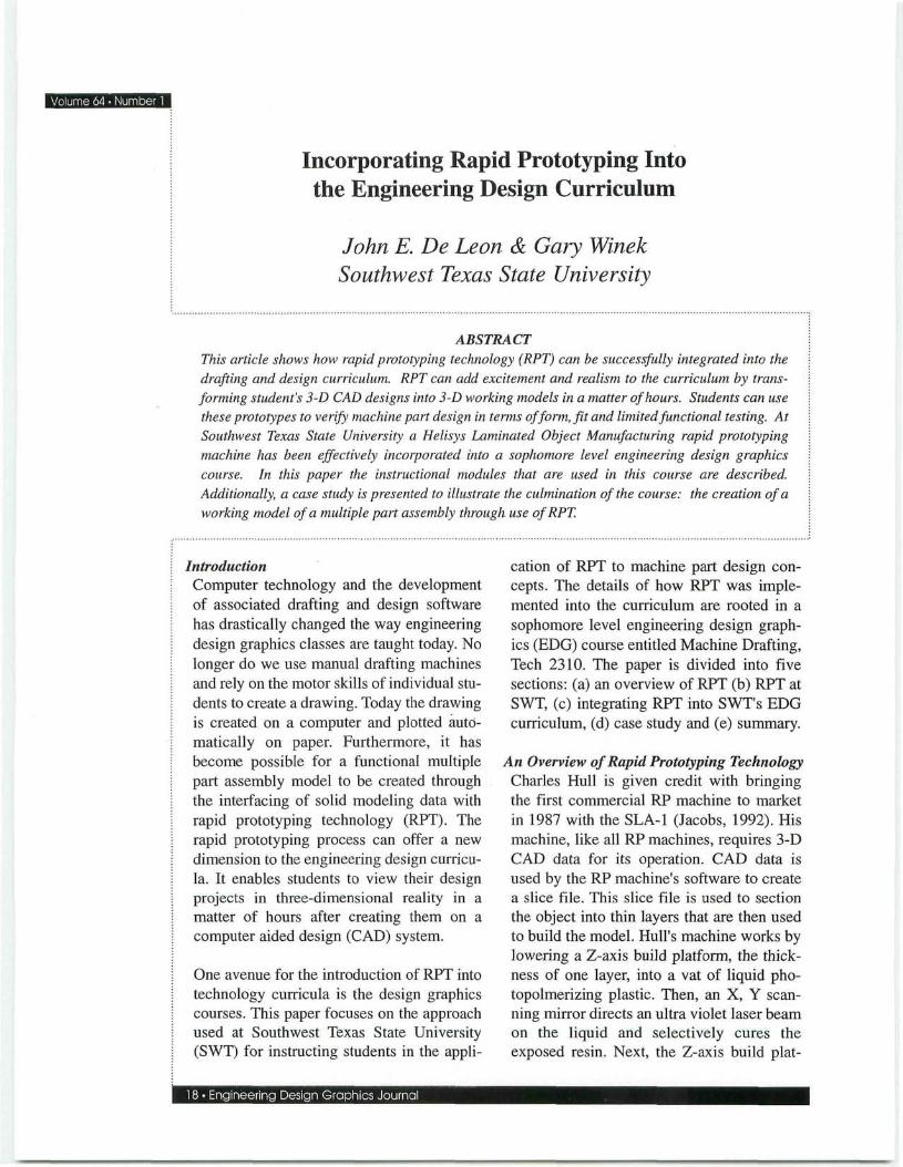
— the part is built (Figure 2). Generally, it takes between 4-8 hours to build a vertical inch of the model depending on the part's geometry. In addition, 10-15% of the build time is needed to decube and finish the part. The LOM Slice software has a time calculator feature that allows the operator to estimate the build time. Also, manual calculations can be used to determine if there is enough paper on the roll to complete the build. After the part is built, it is removed from the build platform, decubed (the excessive cubed material generated during construction is separated from the part), finished and coated with a lacquer or paint for protection. The finished part has plywood like qualities and the paper used in the process is relatively inexpensive, typically costing about $220 per roll. A typical roll is 14" wide x 2,500' long with a paper thickness of .0042". The machine is relatively quiet and is ran while classes are in session.
Laminating roller
Integrating Rapid Prototyping Technology Into Southwest Texas' Engineering Design Curriculum At SWT a sophomore level class, Tech 2310, has been designed to teach engineering design principles using CAD techniques. This course helps prepare manufacturing students for subsequent process engineering and tool design classes. Tech 2310 comprises five modules; each module is accompanied by at least one CAD project.
The first module embraces lecture material on AutoCAD commands and system parameter configuration; materials designation and machine processes; threads and fasteners; English and metric systems of dimensioning; surface texture and surface finishing; working drawings; and title block elements. Students are asked to replicate a three-page working drawing with an orthographic assembly for their CAD assignment.
In the second module, students receive instruction on three-dimensional pictorial representation and on tolerancing for assembly. Specifically, instruction is provided on the methods of calculating types of fit through use of ANSI B4.1 (English) and ANSI B4.2 (metric) standards. The CAD project for this module challenges the student to develop a working drawing along with an exploded isometric assembly drawing of a multiple part pictorial that displays dimensions in basic size and types of fit values.
Sheet material
Figure 2 - Pictorial illustration of the LOM process. The laser cuts the cross-sectional outline in the top layer of the paper and then crosshatches the excess material for later removal. A new layer is bonded to the previously cut layer and a new cross section is created and cut as before.
Geometric dimensioning and tolerancing (GD&T) is the crux of the third module. Symbology, rules of application and interpretation according to ASME Y14.5M-1994 are explored in this module. To reiterate the principles and concepts discussed during lectures, two projects are assigned. In the first, the students are given a
20 • Engineering Design Graphics Journal

blueprint that is dimensioned according to conventional tolerancing practices. A sheet that contains information relating to specific features that are to be controlled with geometric tolerances accompanies this print. Students are to register datum features; affix feature control frames and calculate bonus tolerances where applicable. The second project is a CAD exercise. A blueprint, dimensioned according to ANSI Y14.5M-1982 and containing inadequate applications of dimensioning and detailing practices, is given to the student. The student is required to redraw the print according to ASME Y14.5M-1994 tolerancing and to remedy any detailing discrepancies.
machine operations, construction of models, and use of a prototype to critique the current design from manufacture and assembly standpoints. The following case study shows the RPT project for this module.
Case Study Typically, the enrollment for Tech 2310 averages 20 students. Five different pictorials of a multiple part assembly are passed out. Students with similar assignments work in teams to interpret dimensions, generate solid models and set RP system parameters. The multiple part step bearing assembly, represented in Figure 3, epitomizes the RPT project students complete.
The fourth module focuses on solid modeling and the different types of graphical computer modeling available. Aspects investigated include differences and applications of wireframe modeling, surface modeling and solid modeling. Further instruction is presented on the types of CAD solid modelers available; specifically, Boolean and parametric-feature based modelers are examined. To enhance their understanding of the differences between Boolean and feature-parametric modelers, students are given two solid modeling projects to complete. The same multiple part pictorial CAD project used in module three is reproduced in solid modeling in AutoCAD Release 13. This change in graphic construction methodology shows students the differences between pictorials and solid models. AutoCAD Designer, Release 1.2, a parametric-feature-based modeler, is utilized to construct the second project. This project comprises a different multiple parts assembly than the previous one.
An integral part of the Tech 2310 curriculum is to establish the design/manufacturing interface. This is accomplished in the fifth and final module of the course. RPT material includes introducing the student to both layer additive and layer subtractive processes; "hands-on" exercises including set-up
FIT SPECIFICATIONS
BEARING & BUSHINS Hll/cll FIT
BUSHING &. HANGER H7/u6 FIT
3 ) BEARIN6-FAO 1020 STEEL
FILLETS 3. ROUNDS R3
BUSHING BRASS-FAO
R26 R5 -
O HANGER ASTM M32IOCI (SYMMETRICAL ABOUT 2 AXES)
STEP BEARING
Figure 3 - Pictorial representation of the step bearing. Note. From GRAPHICS FOR ENGINEERING AutoCAD Release 13, 4th Edition, by James H. Earle; Copyright © 1996 by Addison-Wesley Publishing Company, Inc. Reprinted by permission.
For each part, a 3-D database was generated using the AutoCAD Release 13 solid modeling package. The 3-D database CAD files (.dwg) were converted to StereoLithography
De Leon • 21

Volume 64 • Number
(.stl) files. The hanger was modeled in halves because as a whole it would have extended beyond the constructional limits of the RP machine. Subsequently, two separate STL files, one for each half, were generated.
The STL files associated with each part in the assembly were loaded into LOM Slice a proprietary control software developed by Helisys for RP machines. The software is used to construct a "slice file" out of the STL file. As previously mentioned, it is the slice file that is used by the laser to cut each layer of paper. LOM Slice was also used to set process parameters such as cutting speed, laser power, heater speed and platform speed. Loading files and setting system parameters averaged 20-30 minutes per part.
Figure 4 shows the parts as they appeared upon removing them from the RP platform. Figure 5 represents the decubing stage of the process. Each build consisted of excessive material in cubed form and a 1/4-inch wall structure. This wall surrounds and holds the part and excessive material in place during the build. Figures 6 and 7 show the parts as unfinished and finished entities, respectively. Parts were sanded and lacquered to give them a realistic appearance. Combined build time for the parts was approximately 28 hours, decubing required one hour, and the finishing process 2 hours. A lab assistant not enrolled in the course performed approximately 90% of the decubing, and all of the finishing duties. However, students were allowed some time during class to decube for the purpose of exposure to this aspect of the project.
Summary Computer technology has changed the way we teach engineering design graphics and will continue to do so in the future. It is now possible to build a three-dimensional part from a student's solid model CAD drawing using RPT. This ability has opened new curriculum possibilities for instructors that teach CAD related courses. SWT has taken
Figure 4 - Photograph depicting detachment of laminated stack from the machine's elevator plate using .032" steel braided wire. The part and excess material (in cubed form) are held intact by the 1/4" thick wall
Figure 5 - Photograph showing the decubing of the laminated stack. The surrounding wall was removed to allow exposure of the excess material.
22 • Engineering Design Graphics Journal
Winter • 2000
advantage of such an opportunity by incorporating RPT into its Tech 2310 curriculum. Through the advancement of CAD skills and engineering design principles, students are able to physically realize the premise for instruction presented to them via the course modules. This realization is manifested in their ability to interpret a multiple part assembly pictorial for the generation of a 3-D database that is ultimately utilized for the construction of prototypes. Undoubtedly, students who have an understanding of the
relationship between CAD and engineering design principles will be much more attune to the realities of RPT. At SWT, we have taken the initiative to guarantee that students are afforded that chance.
References Jacobs, J. F. (1992). Rapid prototyping and manufacturing: Fundamentals of stereolitho-graphy. Dearborn, ML Society of Manufacturing.
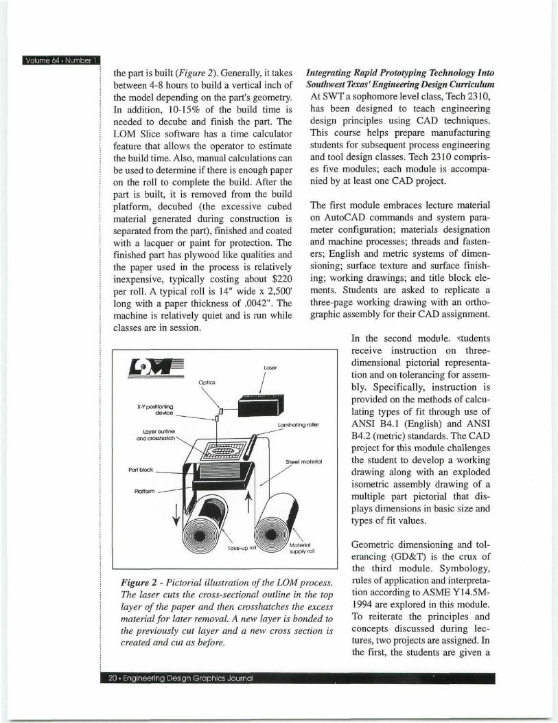
Figure 6 - Photograph of the hanger, one of three parts built on the RP machine. The part is depicted as it looked after decubing the laminated stack.
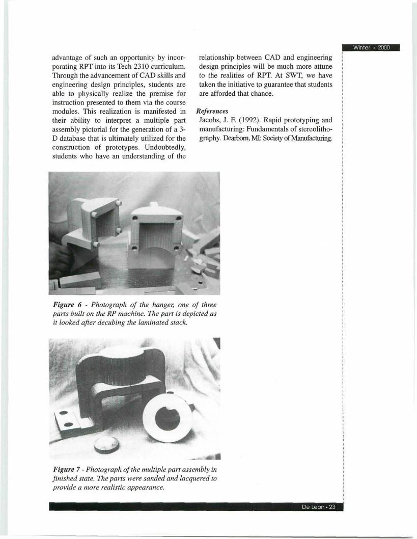
Figure 7 - Photograph of the multiple part assembly in finished state. The parts were sanded and lacquered to provide a more realistic appearance.
De Leon • 23