incorporating main west models manufacturers, wholesalers
TRANSCRIPT

® Australian Railway Kits ABN: 27 416 246 418
Incorporating Main West Models
Manufacturers, Wholesalers and Retailers of Quality Australian Model Railways
PO Box 252 Warwick, Queensland, 4370 Australia
Phone/Fax: 617 4667 1351 Website: www.arkits.com Email: [email protected]
NSWGR C36 4-6-0 BELPAIRE BOILER
LOCOMOTIVE AND TENDER KIT E141 Manufactured Exclusively for AR Kits by DJH Engineering from Patterns owned by AR Kits
PLEASE READ INSTRUCTIONS THOROUGHLY BEFORE COMMENCING ASSEMBLY
CONSTRUCTION
It is important to ensure that all parts are clean, free of "flash" (excess metal on castings) and fit properly. The "flash line" is easily
removed from most areas by scraping gently with a sharp hobby knife - a round blade is more effective than a straight pointed
type. Pull the blade along the "flash line" - several light strokes are better than a single one. Some areas are better cleaned up with
6" jewellers' files. Take care not to flatten round parts by filing too heavily. All locating holes for detail fittings should be pre-
drilled to the size specified in the instructions. Sometimes it is necessary to clean out these holes with a "rat tail" file; take care not
to snap off the tip of the file. Gently wash the castings in warm soapy water to remove mould release residue.
Etched brass items are best removed from the fret by placing the fret on a scrap piece of hard timber (eg Pyneboard) and cutting
the tabs with a large Stanley knife - cut the tab at the point furthest away from the part, then trim the tab off close to the part with
a small pair of quality sidecutters. Hold small parts with a pair of flat nosed (not serrated jaws) pliers while cleaning up with
jewellers' files. Be careful not to distort the etchings; they are difficult to straighten if bent or twisted. Drill all required holes
before assembly, noting the sizes shown on the drawing, because some holes will be difficult to drill after parts are assembled.
A detailed history of the C36 Belpaire locomotives is covered in John Thompson's book "C36" and an excellent Data Sheet is also
available.
Modellers are advised to check photographs of the particular locomotive they have chosen to model, also keeping in mind the era
they are modelling. For assistance in general detailing, modellers are referred to the C36 book and the Data Sheet's plan. The
many photos which appear in Australian railway books and journals are also an excellent source of information.
These kits are designed to give many years of operating pleasure. A little extra time taken during construction will ensure that
your kit will do this. It cannot be emphasised too strongly that the basis of a smoothly operating model is care when constructing
the chassis and valve gear, ie you must double check every step. Check that the axles turn freely in their bearings, check again
with the coupling rods on, then again with the connecting rods on, etc, etc.
Assembly methods
The two main construction methods are:
(a) Low melt solder - Low melt solder is an excellent medium for use with white metal kits. It is quick and easy providing a
stronger joint than can be achieved with glue. It has the added advantage of easily repairing minor casting flaws, and because of
the relatively low temperature, many parts can be held in the fingers while soldering. Brass to white metal joints can also be made
by "tinning" the brass first with normal solder. Low melt soldering requires the correct type of soldering iron (eg Dick Smith
T2200). These irons have temperature control, as low melt solder only requires around 200 degrees centigrade. You should use
special low melting point solder available from AR Kits.
Page 1
IT IS ADVISABLE NOT TO ATTEMPT TO SOLDER ANY CASTINGS WITH A STANDARD SOLDERING IRON
(b) Glue - Superglue and Plastibond are two types of glues suitable for use with this kit. Some modellers prefer to superglue major
joints first then "fillet" the joint with Pastibond. Small detail parts are best glued with Superglue. Glue is not recommended for
those parts needing good electrical contact, such as the tender bogies.
It does not matter which method you choose but dry fitting parts will ensure a good fit.
Electrical pickup.
The electrical system used on these kits is called "half live". Looking from the top facing forward the locomotive chassis collects
current from the live wheels on the right-hand side, shown as LS (live side) on the drawings. The tender is insulated from the
locomotive chassis by a plastic bush and current is collected from the wheels on the left-hand side of the tender.
Cleaning up/Painting
On completion, any areas which were soldered should be washed using a soft brush and methylated spirits to remove all traces of
flux, if this is not done the paint will not adhere properly to these areas. Alternatively an excellent pressure pack flux remover is
also available from Dick smith stores. Then wash thoroughly in warm soapy water. Rinse with clean water and allow to dry
thoroughly before applying a suitable self-etch primer.
Spare Parts
Spare parts are available on a replacement basis. Should any part be missing or damaged contact AR Kits for a replacement.
Should you have any problems with the Mashima motor please do not attempt to repair it yourself - return the motor to us.
Mashima will not replace motors which have been tampered with.
Should you have any queries or problems with construction please drop us a note and we will do our best to advise. Likewise we
would be pleased to hear any suggestions you may have for improving the kits or instructions.
General
The following drill sizes are required: 0.5mm, 0.6mm, 0.7mm, 0.8mm, 0.9mm, 1.0mm, 1.2mm, 1.5mm,
1.6mm,1.9mm,Z.Omm,2.lmm, 3.7mm.
During construction refer to the drawings at all times. A number of parts are quite similar, so double check if in doubt. Note that
attached to the instructions is a photocopy of the lost wax brass castings with each part numbered for easy identification. In the
general instructions the part numbers are shown in brackets.
The instructions sometimes refer to the right-hand and left-hand side. This is taken as viewing the model from above and looking
forward.
To minimise the risk of losing parts, do not remove them from the etched fret or the plastic packing until you are ready to use
them. We recommend that you start construction with the tender.
Safety First
These models are not toys and are not suitable for young children. White metal castings contain lead and
modellers are advised to wash their hands after working with unpainted white metal castings. When using
superglue, solder or when spray painting, ensure your work area is well ventilated
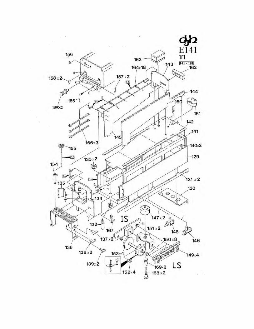
Tender Drawing T1 (Parts 141 - 181)
Bend up the tender body (141) as shown and solder the sides to the end making sure it is square. Glue in tender deck side supports
(152x2), and tender deck back support (153), ensuring that they are correctly seated. Bend buffer beam (142) as shown and fix to
the body. Fix the tender mainframes (143x2) to the tender body and buffer beam keeping everything square. Fit the drawbar pin
(144) using the two M2 nuts (145x2). Fit the turret front (146) keeping everything square. Next fit the turret doors (147) noting
that this component does not need soldering as the tabs can be folded back flat to secure in place. Fit tender steps/floor (148) to
the turret front (146) and fit flat step treads (149x2). Fold ends of steps (150x2 & 151x2) before fixing in place. Bend the tender
deck (154) as shown to form the coal bunker floor and test to make sure it fits correctly in the tender. Fit the turret sides (156) and
(157) to the tender deck/bunker floor, soldering or gluing the tabs at the back only at this stage. Solder in tender body lamp iron
(168).
Page 2

Fit the assembly to the tender as shown, gluing the deck sides to the white metal supports and soldering or gluing the front tabs
of the turret sides to the tender floor/coal bunker floor (154) bending as shown so that the bent floor of this part is level and fits
the turret front correctly. Fit the turret back (155).
Short one wheel of each of the tender axles (165x4) using 1.Omm wire - note that one wheel on each axle has been predrilled to
facilitate this. Bend up the bogie cross-members (163x2) as shown. Fit the axle bearings (162x8) to the bogie side frames
(161x4), using low melt solder if necessary. Now assemble the bogies as shown using the shouldered screws (152x4), making
sure that the shorted wheels are both on the same side of each bogie. Fit the bogie bearings (159x2) to the tender floor. These
have been pre-tapped to accept the bogie fixing screws (180x2).
Now fit the bogies to the tender using the bogie fixing screws and springs (181x2), making sure that the shorted wheels are all on
the left side of the tender.
Fit tender air tank (158) and tender brake cylinder (160) under tender. Complete detailing of tender by fitting brake handle
standard (166), brake hand wheel (167), footplate lamp irons (169x2), marker lights (170x2), buffers (171x2), air vent (172),
water filler (173) tool box A (174), tool box B (175), brake pipe (177), fire irons (178x3) and tablet/staff exchanger (179). Slip
six handrail knobs (176) onto a length of.4mm wire and fold as per the drawing. Fit remaining hand rail knobs to the tender
before placing tender handrail (with previously fitted knobs) in place.
Chassis Drawing 1(Parts 1 - 32)
Remove any tabs from the frames (1 and 2). Carefully clean out the axle holes with a 3.7mm drill bit and push fit the axle bushes
(3x6). The bushes should be a firm fit in the frames - any loose bushes should be soldered in place.
Bend the motor mounting plate (10) as shown.
Assemble the chassis using the chassis spacers (5x2), spacers (6 and 7), motor mounting plate, and screws (4x6).
Solder power clips (12 and 15) to the motor leads as shown. Mount the motor (11) to the motor mounting bracket using screws
(13x2) (supplied with the motor), at the same time fixing the positive motor lead.
Cut M2 screw (14) to 10mm and fit to chassis using insulated bush (16), insulated washer (17) and M2 nut (18). Trim spring (19)
to 6mm and fit as shown followed by loco tender connection (20), spring plate (21) and M2 nut (22). M2 screw (31) and M2
screw cut to 9mm (32) are used later to mount the body.
Remove the axle nuts (24x6) from the axles (9x3) and fit the live (uninsulated) wheels (26x3) in place with three of the axle nuts.
Place a spacer washer (25) onto the front driving axle positioning the axle into the right hand front axle bush, locating the gearbox
axle gear (8) onto the axle. Push the axle through the opposite axle bush, fit another spacer washer and then fit an insulated wheel
(23), quartered so that the crankpin on the right hand wheel leads that of the left hand wheel by 90 degrees when the axle rotates
forward, and fix with an axle nut.
Move the gear to one side of the axle, place a small spot of superglue or Loctite 601 on the centre of the axle and push the gear
into the centre of the axle. Make sure that the gear is square with the axle. Be careful not to get any glue or Loctite in the axle
bushes. Fit the other axles and wheels as per the drawing. Make sure that all axles rotate freely in the axle bushes.
Now fit the crankpins (27x6) to the wheels using Romford axle nut screw driver, a spot of superglue or Loctite 601 on the thread.
Glue the counterweights (29x4) and (30x2) to the wheels. Note that not all of the C36 class locomotives had the extra
counterweight parts on the centre drivers, and for those that did, the position varied in relation to that of the main counterweight.
Check photographs of the locomotive you are modelling. Glue axle covers (28x6) to the axle nuts.
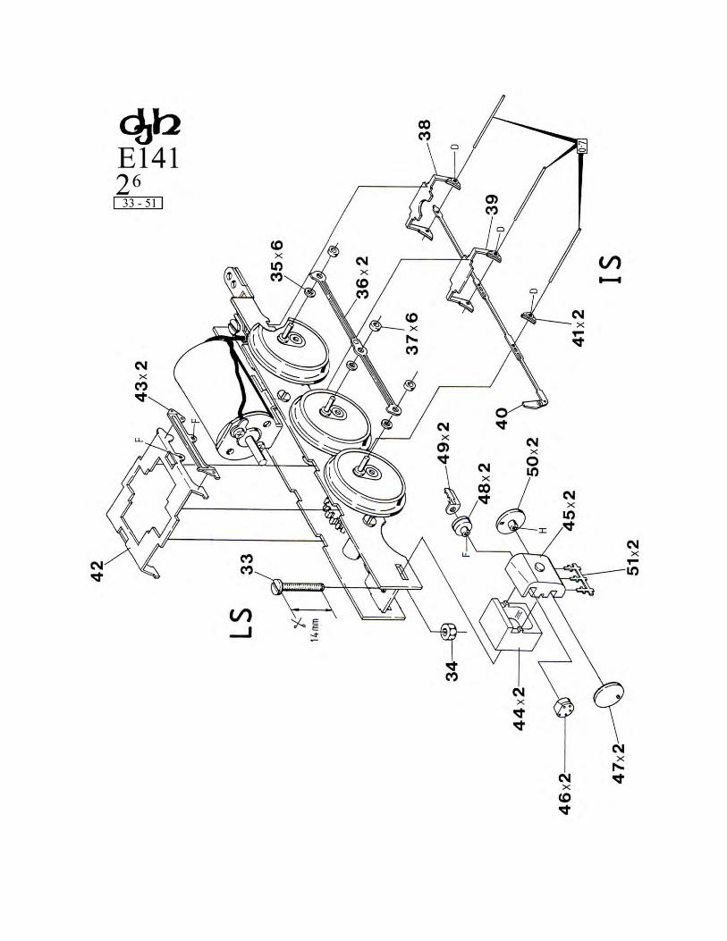
Chassis Drawing 2 (Parts 33 - 51)
Cut M2 cheese head screw (33) to length and then fix to the chassis spacer with nut (34). Fit a crankpin spacer washer (35x6) to
each crankpin and fit the coupling rods (36x2). Place a piece of paper on the crankpins and then washers (37x6). The paper will
prevent glue or solder from reaching the coupling rods when soldering the crankpin washers in place. Note: For easy removal of
the coupling rods during testing, painting etc, strip a short length of insulation from some fine (approx lmm dia.) electrical wire.
Push this "tubing" onto the crankpins as a temporary retainer. Complete both sides, cutting the crankpins flush on the front and
rear drivers; leave the centre driver crankpins at this stage. File the front crankpin washers down to about half their thickness to
help clear the motion gear. Remove the paper and oil all moving parts. Again make sure the moving parts move freely.
Page 3
Fold rear brakes (38) and centre brakes (39) and fix to chassis. Locate pull rod (40) between frames and to the right hand side,
then pass through the.7mm wire as shown. Again using.7mm wire fix leading brake shoes (41x2) in place. Trim .7mm wire flush
with outside face of brakeshoes.
Assemble the cylinders as shown, using cylinder blocks (44x2), cylinder bodies (45x2), front valve covers (46x2), front cylinder
covers (47x2), rear valve covers (48x2), valve crosshead guides (49x2) and rear cylinder covers (50x2). Then fit cylinder drain
cocks (Slx2).
Fit the cylinders to the chassis making sure that the centreline of the cylinders lines up with the centreline of the centre axle.
Fold the motion bracket (42) as shown and glue or solder the motion bracket detail plates (43x2) (left and right hand) onto the
motion bracket. Fix the motion bracket to the chassis.
Chassis Drawing 3 (Parts 52 - 72)
Trim the piston rod (54x2) as shown and fit to the slidebar (57x2) and then fold the slidebar as shown. Fit the slidebars to the
cylinders, fitting the piston rods into the cylinders.
Fit the partly assembled valve gear (55x2) to the cylinder and then, together with partly assembled valve gear (58x2), to the
motion bracket using short 14BA screw (59x2) and nut (60), making sure that (58) is outside (55) and both are inside the motion
bracket frame.
Fit the small end of the connecting rod (52x2) and the valve gear (55) to the crosshead using the long 14 BA screw (53x2) and nut
(56x2).
Making sure that the spacer washer (37) is still in place, fit the big end of the connecting rod to the crankpin of the centre driver,
then washer (61x2) followed by the return crank of the valve gear (58). Set the return crank as per the inset drawing and glue or
solder in place.
Throughout the assembly of the valve gear make sure that all components move freely.
Short one wheel on each of the locomotive bogie axles (67x2) using 1.0mm wire. Fit the wheel inserts (69x4) to the wheels and
assemble the bogie (66) using keeper plates (68x2) making sure that both shorted wheels are on the same side.
Fit the bogie to the screw on the front spacer of the chassis using the washer (70), spring (71) cut to length as shown, and M2 nut
(72), making sure that the shorted wheels are on the right hand side of the chassis.
Assemble the gearbox (62) as per the accompanying instructions trimming the worm shaft as shown. Do not force the worm onto
the shaft. Carefully ream the worm bore using a 2.0 mm drill or hand reamer so that the worm fits the shaft without undue force.
Use a spot of superglue or Loctite 601 to permanently fix in place. Clean the shaft of excess glue or Loctite thoroughly.
Trim the rubber sleeving (63) to length as shown and fit to the wormshaft of the gearbox - check that the ends of the wormshaft
and motor shaft are free of sharp edges which could damage the tubing. Fit the sleeving to the motor and fit the gearbox onto the
axle gear. Fit the gearbox keeper plate (64) to the gearbox using screws (65x2).
Locomotive Cab Drawing 4 (Parts 73 - 91) Before folding the cab (73) and fit step (76).
Solder M2 nut (77) to the cab floor (74) and then fix to the cab (73). Fit the cab deck plate (79) to the cab back plate (78) and then
fix the assembly to the cab. Fit the handrail cowlings (80x2) to the inside of the cab sides behind the openings. Fit the cab to the
cab valance plate (75).
Fold the cab steps and drawbar (84) as shown and fix the other steps (85x2) (A) and (86x2) (X). (A and X are etched on the back
of the steps). Fix the left and right hand injectors (87) and (88) to the back of the steps and then fix the unit to the underside of the
cab valance plate.
Page 4

Glue the plasticard (90) to the fall plate (89) and trim the plasticard to 0.5mm larger than the fall plate on the sides and rear (away
from the tabs). Bend the tabs on the fall plate and fix to the cab floor using 0.7 mm wire as shown. Fix the cab seats (81), followed
by the boiler backhead (82).
Fix handrails to the front of the cab as shown using short handrail knobs (91x7) and the handrails (0.4 mm wire) to the sides of the
cab
.
Fix the cab roof (83) in place.
Locomotive Drawing 5 (Parts 92 - 120)
Clean up the footplate (92) removing flash and feed sprue remnants and make sure it is flat and square. Glue or solder an M2 nut
(93) to the footplate as shown. Test fit the footplate to the cab and adjust the locating lug if necessary.
Drill all holes in the footplate, boiler (95), firebox (94) at this stage (noting the spigot sizes of the fittings) because some holes
would be difficult to drill later on.
Place the boiler and firebox on a flat surface (hang the smokebox end over the end of the flat surface) and glue or solder together.
Glue or solder the cab to the footplate. Fit the boiler/firebox assembly to the footplate and fix in position with the back of the
firebox flush with the end of the footplate and butted to the cab
.
Noting the drill sizes shown on the drawing, fit detailing parts (96) through (125). Also note that there are optional sandbox fillers
(118x2) or (119x2) and reversing gear (122) and (123) OR (124) and (125). These alternative parts are marked *. There were six
locomotives fitted with power reversing equipment late in their lives - 3638, 3642, 3644, 3651, 3652 and 3654. However, only
3638 had the power reverse mechanism without modifications to the cab sides to accommodate sanding gear for the rear drivers,
and then only fitted for a short time. The other locomotives had the sanding gear fitted at the same time as the power reverse and
3638 had sanding gear fitted also. Check photographs of the locomotive you are modelling. Locomotive 3616 was fitted with a
geisl ejector in 1957. This modification included a new chimney, and this part (101) is included as an option.
Locomotive Drawing 6 (Parts 126 - 140)
Fold guard irons (129x2) and buffer beam step (134) as shown before fitting. Finish detailing the locomotive body using steam
generator (126), dome regulator pivot valve (127), smoke box regulator pivot valve (128), whistle (130), dome safety valve (131),
pump (133) and brake pipe (135). Noting wire sizes shown on drawing fashion handrails and fit using hand rail knobs (136x14),
handrail poles long (137x4), handrail poles medium (138x2), handrail poles short (139x2) and pipe valves (140x3).
Consult photographs if unsure of the positioning of pipes and handrails or the drawing seems unclear. Test fit to the chassis using
cheesehead screws (31) and (32) (trimmed as per drawing 1).
Lightly oil the mechanism and test run, checking for electrical "shorts" on sharp curves etc. Also check that the motor does not
overheat due to chassis binding.
24 Feb 2009
Page 5