incorporate mpact into consortium for advanced simulation of lwrs tiamat … · 2017-09-18 ·...
TRANSCRIPT

Consortium for Advanced Simulation of LWRs
CASL-U-2015-0022-000
Incorporate MPACT into TIAMAT and
Demonstrate Pellet-Clad Interaction (PCI)
Calculations
Kevin Clarno Oak Ridge National Laboratory Roger Pawlowski Sandia National Laboratory December 16, 2014
CASL-U-2015-0022-000

K. Clarno and R. Pawlowski
ABSTRACT
CASL (the Consortium for Advanced Simulation of LWRs) is investing in the development of themulti-dimensional Bison fuel performance code for both transient and nominal peformance analysis.The MPACT whole-core neutronics capability has been integrated with the Cobra-TF sub-channel solverto provide a neutron-transport based core-simulator with substantially improved fidelity over traditionaldiffusion-based core simulators. The Tiamat code is being developed to provide an integrated tool forpredicting pellet-clad interaction and improving the high-fidelity core simulator.
This manuscript documents the completion of the “L3:PHI.CMD.P10.01” CASL milestone to“Incorporate MPACT into Tiamat and demonstrate PCI calculations”. [?] The MPACT code has replacedInsilico as the primary neutronics component of Tiamat and is currently under nightly testing. Thealgorithm for incorporating (single-cycle) depletion has been documented and discussed with the leadMPACT developers. Tiamat has been compared with MPACT+CTF for a suite of single-pin analyses andresults agree very well. Several large calculations have beeen executed on EOS to model the full 17x17PWR assembly and a 5x5 cross of PWR assemblies. With the completion of this milestone, Tiamat withInsilico is being placed on idle and continued develoment on Tiamat will focus on the MPACT version.
Key Words: Bison, Peregrine, MPACT, Cobra-TF, Tiamat
1 INTRODUCTION
Pellet-Cladding interaction (PCI) is a local effects cladding failure mechanism that can occurin various fuel rod locations in the reactor core, depending on the core operating strategy, thepower maneuvering approach, and the fuel rod design characteristics. The related variables thatinfluence the potential for cladding failure include the rod-average and local burnup, the rod-averagepower and the power axial distribution both prior to, and during, a power maneuver. An importantcapability for the assessment of PCI failure is the ability to calculate a key figure of merit as afunction of position within the reactor core that identifies a subset of rods that require more detailed3-D thermo-mechanical simulations of PCI.
The single-rod fuel performance code Bison (previously called Peregrine) can calculate thecladding hoop stress as a function of operating conditions using an 2-D axi-symmetric fuel rodgeometric representation. Previous studies have demonstrated that maximum cladding hoop stresscan serve as a figure of merit for the potential for PCI failure. Tiamat is being created to couple theBison fuel performance calculation with a full core representation of the fission density and coolantconditions for each fuel rod within the core. This coupling provides a full core calculation of themaximum cladding hoop stress that can then be used to identify the fuel rods and assemblies ofinterest for further detailed PCI calculations.
VERA is a suite of simulation capabilities, as shown in Figure 1, which are being developed inorder to address the CASL Challenge Problems. VERA-CS (Core Simulator) is an integrated suiteof VERA that will provide all of the functionality of a traditional core simulator, but with muchhigher fidelity. The current version of VERA-CS is integrated within the main MPACT driver andintegrates the Cobra-TF (CTF) sub-channel thermal-hydraulics and fuel heat transfer models withthe full functionality of the MPACT neutronics capability. Tiamat has been developed for analysis of
Page 2 of 22CASL-U-2015-0022-000

Incorporate MPACT into Tiamat and Demonstrate PCI Calculations
PCI and currently integrates a portion of the Bison fuel performance code with the CTF sub-channelthermal-hydraulics and a subset of the MPACT neutronics capability. This report documents thealgorithm that will be used by Tiamat to incorporate more of the functionality of MPACT.
Figure 1. The VERA code suite.
This report documents the completion of CASL Milestone L3:PHI.CMD.P10.01, “IncorporateMPACT into Tiamat and Demonstrate PCI Calculations.” [?] The goal of this report is to documentthe incorporation of MPACT into Tiamat as a replacement for Insilico and define the path forwardwith respect to the addition of depletion. The report documents also provides a discussion abouthow multi-cycle depletion could be handled in Tiamat. Section 2 describes the overall design ofTiamat, including the sub-components. Section 3 describes the conversion from Insilico to MPACT.Section 4 describes the unit testing and single pin parametric study of Tiamat with MPACT. Section5 describes the larger problems executed to demonstrate the capabilty for full assembly problems.Section 6 describes the algorithms that could be used for various depletion scenarios. Section 7describes the unit tests that will be required to test the ability of each of the physics codes to providethe functionality required by Tiamat. Section 8 summarizes the report.
2 DESIGN OF TIAMAT
This section describes the overall design of Tiamat and the individual applications used inthe coupling. Tiamat is named for a multi-headed dragon tracing back to Babylonian mythos toreflect that this coupled driver allows for simple extension to additional physics and couplings.A previous version of Tiamat leveraged the Insilico neutronics code, but that is in the process ofbeing deprecated because MPACT is the driver for VERA-CS. Section 2.2 describes the MPACTneutronics code. Section 2.4 describes the Bison nuclear fuel performance code. Section 2.5
Page 3 of 22CASL-U-2015-0022-000

K. Clarno and R. Pawlowski
describes the data transfers that couple each of the codes. Section 2.6 describes the PIKE numericalanalysis kernels that provide the coupled physics solvers, and Section 2.7 describes the Tiamatdriver that integrates all of the other pieces.
2.1 COBRA-TF (CTF)
COBRA-TF (CTF) is a thermal-hydraulic simulation code designed for Light Water Reactor(LWR) analysis [3]. CTF has a long lineage that goes back to the original COBRA developed in 1980by Pacific Northwest Laboratory under sponsorship of the U.S. Nuclear Regulatory Commission(NRC). The original COBRA began as a thermal-hydraulic rod-bundle analysis code, but subsequentversions of the code have been continually updated and expanded over the past several decades tocover almost all of the steady-state and transient analysis of a both PWRs and BWRs. CTF is beingdeveloped and maintained by the Reactor Dynamics and Fuel Management Group (RDFMG) atthe Pennsylvania State University (PSU). CTF includes a wide range of thermal-hydraulic modelsimportant to LWR safety analysis including flow regime dependent two-phase wall heat transfer,inter-phase heat transfer and drag, droplet breakup, and quench-front tracking. CTF also includesseveral internal models to help facilitate the simulation of actual fuel assemblies. These modelsinclude spacer grid models, a pin conduction model, and built-in material properties. CTF uses atwo-fluid, three-field representation of the two-phase flow. The equations and fields solved are:
• Continuous vapor (mass, momentum and energy)
• Continuous liquid (mass, momentum and energy)
• Entrained liquid drops (mass and momentum)
• Non-condensable gas mixture (mass)
Some of the reasons for selecting CTF as the primary T/H solver in the VERA core simulatoris the modest run-time, as compared to CFD (Computational Fluid Dynamics), the fact that it isbeing actively developed and supported by PSU, and for the ability to support future applicationssuch as transient safety analysis and BWR (Boiling Water Reactor) and SMR (Small ModularReactor) applications. CTF is a time-dependent, control volume code that enforces conservationbetween volumes and is being used within Tiamat in a steady-state mode. Internally CTF uses apseudo-transient solver to converge towards a steady-state convergence for a particular flow/powerstate.
2.2 MPACT
The reactor core simulator MPACT has been developed collaboratively by researchers at theUniversity of Michigan (UM) and Oak Ridge National Laboratory (ORNL) to provide an advancedpin-resolved transport capability within VERA. The key characteristics of the MPACT code include
Page 4 of 22CASL-U-2015-0022-000

Incorporate MPACT into Tiamat and Demonstrate PCI Calculations
the subgroup method and the embedded self-shielding method (ESSM) for resonance treatment,depletion capability based on the ORIGEN exponential matrix method, and a whole core solver witha 2-D/1-D synthesis method on the frame of 3-D coarse mesh finite difference (CMFD) method forwhich axial and radial correction factors are obtained from 2-D method of characteristics (MOC)and 1-D nodal expansion method (NEM) or Simplified PN, respectively. Reference [1] contains adetailed description of the methods used in MPACT as a part of the VERA Core Simulator.
In addition, MPACT contains other ”Feedback Solvers” to execute code that will effect the crosssections during a multi-cycle core depletion. One of the primary effects is due to changes in the fueltemperature and moderator density. MPACT contains both an internal simplified thermal-hydraulicmodel and a direct connection to CTF.
2.2.1 MPACTs Internal TH
The thermal-hydraulic model that is internal to MPACT is based on a one-dimensional fuelconduction at a series of axial nodes coupled to a one-dimensional, single-phase flow model thatneglects cross flow between the channels. The fuel thermal conductivity models are not dependentupon the burnup, temperature, or porosity of the fuel. The gap heat transfer coefficient is fixed anddoes not change during a multi-cycle depletion calculation. The clad thermal conductivity modelsdoes not depend on the porosity of the fuel either. Because the mechanical changes to the fuel andcladding or not modeled it is incapable of modeling PCI, but can provide an estimate of the fueltemperature and clad coolant density.
2.2.2 MPACTs direct coupling with Cobra-TF
The direct coupling of MPACT to CTF allows VERA-CS to leverage a higher fidelity fuel heattransfer model (2D in R-Θ) and account for both cross-flow and boiling. However, the fuel thermalconductivity models are not dependent upon the burnup, temperature, or porosity of the fuel. Thegap heat transfer coefficient is fixed and does not change during a multi-cycle depletion calculation.The clad thermal conductivity models does not depend on the porosity of the fuel either. Becausethe mechanical changes to the fuel and cladding or not modeled it is incapable of modeling PCI, butalso can provide an estimate of the fuel temperature and clad coolant density.
2.3 Predictor-Corrector Solution Algorithm
The MPACT solution algorithm for single-cycle depletion problems with feedback is as follows:
1. Solve the coupled problem at the first state with the initial isotopics
2. Loop over all state-points in the problem
(a) Loop over depletion steps of this state point
Page 5 of 22CASL-U-2015-0022-000

K. Clarno and R. Pawlowski
i. Isotopic Predictor: Given the coupled solution at the beginning of the step, solvefor the isotopics at the end.
ii. Prediction Solve: Given the predicted isotopics at the end of the step, solve thecoupled problem at the end.
iii. Isotopic Corrector: Given the average coupled solution, solve for the isotopics atthe end.
iv. Coupled Solve: Given the corrected isotopics at the end of the step, solve thecoupled problem at the end.
2.4 Bison
The Bison fuel performance code is being developed to provide a single-rod, fuel performancemodeling capability to assess safety margins, and the impact of plant operation and fuel rod designon the thermo-mechanical behavior, including Pellet-Cladding Interaction (PCI) failures in PWRs[11,12]. PCI is controlled by the complex interplay of the mechanical, thermal and chemical behaviorof a fuel rod during operation, and therefore modeling PCI requires an integral fuel performancecode to simulate the fundamental processes of this behavior. Bison is built upon INL’s MOOSE/Foxpackages, which are also common to the Bison code [8]. This code architecture uses the finiteelement method for geometric representation and MOOSE uses a Jacobian-free, Newton-Krylov(JFNK) scheme to solve systems of partial differential equations [9]. While the MOOSE frameworkcan solve either steady state or transient problems, the Bison application is a transient code becausethe material models are strongly influenced by the time history. The focus of Bison is to establish amodern computational framework based on the finite element method to represent the geometricdomains of a single nuclear fuel rod composed of UO2 ceramic pellets contained within a Zircaloytube. The Bison framework consists of a numerical representation of the heat conduction and theequilibrium mechanics equations, which are coupled via the temperature and displacement variables.A material property and constitutive model library has been incorporated into the framework thatallows for thermal, mechanical, and chemical property models and irradiation effects models, suchas fission product-induced swelling or irradiation creep, to be utilized and modified easily. Finally,the framework allows for versatile time-marching algorithms to capture the different temporalregimes associated with fuel performance, such as burnup accumulation over several years followedby a rapid power ramp over several minutes. For this milestone, the fuel rod geometric representationin Bison was a 2D R-Z axially-symmetric, smeared-pellet model. The base mesh is shown in Figure2, where the red region is fuel and the blue region is cladding; the radial dimension is scaled by afactor of 100.
Because Tiamat simulates thousands of fuel rods in parallel, Bison is accessed using theMOOSE MultiApp capability. A separate instance of Bison is built for each fuel rod and theapplications are aggregated and solved via the MOOSE MultiApp object interface and coupled tothe other physics application components: CTF and Insilico via the Data Transfer Kit (DTK). Bisoncomputes the thermal expansion and elastic deformation of the cladding and pellet in response tothe energy generation (heat) and mechanical forces. The interaction of the temperature solution and
Page 6 of 22CASL-U-2015-0022-000

Incorporate MPACT into Tiamat and Demonstrate PCI Calculations
Figure 2. 2-D Axisymmetric Finite Element Mesh (FEM) Representation of a Fuel Rod.
the mechanical solution is non-linear due to the complex dependency of the material properties ontemperature, stress, and strain. As a result, Bison must model the heating of a fuel rod from zeropower to full power to appropriately account for these non-linearities. While a core-simulator istraditionally uses a quasi-static model, with a series of steady-state calculations, the material modelswithin Bison are inherently time-dependent. Therefore, Bison was used in a way to approximatesteady-state conditions, as discussed in the following section of this report. Advancements in thisapproximation were a significant part of this milestone.
2.5 DATA TRANSFERS
To couple the codes, data must be passed between each code. There are five data transferobjects implemented in Tiamat for this capability. All data transfers have to account for patternsfor parallel communication, unit conversions, pin axis orientation, and active fuel offset height.DTK was used for determining the parallel MPI communication mappings and for moving alldata between codes. As part of this procedure, DTK performs an intersection search for targetcoordinate points in source geometry representations. A very valuable benefit was that if a targetpoint was not found in the source geometry, it was recorded and reported. This was critical intracking down misaligned meshes and coordinate transformation issues between codes. At runtime,if a user makes a mistake in specifying the geometry/mesh information, DTK will help to catchthis. All three codes use different unit systems that are to be converted during data transfers:CTF uses English units, Insilico uses a mix of CGS and MKS units, and Bison used MKS units.Pin-axis alignment deals with the direction that the fuel rod axes are oriented. CTF and Insilicoalign the pin axis in the ‘z’ direction in three-dimensional (3D) Cartesian coordinates, but Bisonuses a two-dimensional (2D), axially-symmetric ‘R-Z’ model with the pin axis aligned on thesecond coordinate index. In the MOOSE MultiApp DTK interface, an internal translation from2D cylindrical to 3D Cartesian coordinates is provided, but it keeps the pin aligned in the secondcoordinate direction (‘y’ direction in Cartesian). Therefore, when implementing data transfersinvolving Bison, the ‘y’ and ‘z’ coordinates of the target coordinate point had to be swapped before
Page 7 of 22CASL-U-2015-0022-000

K. Clarno and R. Pawlowski
passing to the DTK detection algorithm. In addition, each code models different spatial componentsof the reactor above and below the active fuel region; Insilico models the upper and lower coolantplenums, Bison models the full fuel pin, and CTF was restricted to coolant adjacent to the activefuel. This results in different origins in the axial dimension for each code. Therefore, each transfermust adjust the coordinates to a common specification when communicating with DTK so that theactive fuel regions are aligned between codes during the source/target intersection search.
2.6 SOLVERS
The PIKE (Physics Integration KErnels) solver package, a replacement for LIME 1.0, wasrecently given DOE copyright approval for release in the Trilinos framework. PIKE contains both aGauss-Seidel and a Gauss-Jacobi solver for multi-physics applications, along with a time-dependentcomponent that will be utilized for the transition to depletion. PIKE includes simplified modelinterfaces, explicit separation of global and local convergence criteria, a user defined convergencetest hierarchy, local application convergence checks, flexible unified user control via observer designpattern, user extensible factories to allow for solvers to enforce the open-closed principle, andsimplified structured parameter and response interfaces.
2.7 TIAMAT
Tiamat couples these physics components using DTK to transfer the data and PIKE to solvethe math.
3 CONVERSION FROM INSILICO TO MPACT
To convert the Tiamat code from using Insilico to using MPACT, there were several modifi-cations required. The Insilico-based, LIME-coupling of neutronics with Cobra-TF was designed,developed, tested, and stable before the MPACT interface was required. Therefore, the developmentof the LIME ModelEvaluator and DTK interface for MPACT leveraged all of the experience fromInsilico and was able to replciate the design and many of the unit tests.
The original Tiamat development created a new PIKE-based ModelEvaluator that had a directconnection to the Insilico drivers and by-passed the LIME ModelEvaluator. During FY14, asignificant refactoring of the Insilico interfaces was performed to allow for a LIME-free driver,with an extension for both PIKE and LIME, but this refactoring was not done for MPACT. Aftersignificant discussion and debate about the future of Insilico and cost of maintaining Tiamat’sbackwards compatability with it while advancing the MPACT version forward with the additionof depletion, three priorities became clear: (1) keep the Insilico version around and under test, (2)don’t let that version impede progress with MPACT, and (3) minimize the cost of incorporatingfixes needed for the MPACT version into to Insilico version.
To complete this milestone, there were several modifications required to Tiamat and MPACT:
Page 8 of 22CASL-U-2015-0022-000

Incorporate MPACT into Tiamat and Demonstrate PCI Calculations
• Generalization of Insilico to Neutronics
• Creation of a LIME-free MPACT ModelEvaluator
• Separation of Insilico and LIME versions of Tiamat
• Generalization of PETSc Initialize in Cobra-TF
To ensure that the Insilico version is maintained and tested, we have created a separate packagesfor the MPACT version. To minimize the cost of incorporating fixes into Insilico, we chose togeneralize the Insilico version to “Neutronics” before breaking off a copy for the MPACT version.Therefore, all references in Tiamat to Insilico were replaced with Neutronics and the connection ofthe NeutronicsModelEvaluator (no longer InsilicoModelEvaluator) to Insilico was generalized touse a non-code-specific API. With this change, there are only a few differences in Tiamat betweenthe current versions of MPACT and Insilico that could be eliminated, but don’t make sense tobecause that would likely impede progress with MPACT; the rest of the lines of code in each sourcedirectory are identical.
• Trilinos, not Nemesis, initializes and finalizes MPI.
• Insilico requires an explicit call to print the final output.
• Different headers are included in the NeutronicsModelEvaluator.
Because the MPACT model evaluator was hard-wired to work with LIME, we needed to createa general MPACT driver, which had a DTK adapter, and Tiamat could extend with a PIKE-basedModelEvaluator. In Insilico, this involved modifying the LIME-based ModelEvaluator to be asimple extension of both the general driver and the LIME ModelEvaluator. For MPACT we simplymade a copy because we don’t envision retaining the LIME-based coupling much longer since CTFcan be executed within MPACT.
With the creation of two separate TriBITS subpackages for Tiamat-with-Insilico and Tiamat-with-MPACT, we were able to create a suite of tests specific to Tiamat with MPACT. The Insilico-based Tiamat retained all of the original tests and several were ported to the MPACT version.Additionally, the CTF+MPACT tests based on the LIME coupling were ported to work with Tiamatand are tested nightly as well. The specific tests, with a description, are provided in Section 7.
Historically, there have been many challenges when integrating a new component into a VERApackage. Examples include: integrated CTF and Insilico took over 1.5 years; integrating CTF andMPACT was over 6 months later than projected; creating Tiamat with MOOSE embedded lead to amassive overhaul of TriBITS to support external codes needing to work with Trilinos, among otherthings. When we decided to integrate MPACT, there was only a single hurdle - a conflict associatedwith PETSc initialize.
Page 9 of 22CASL-U-2015-0022-000

K. Clarno and R. Pawlowski
PETSc has a single global variable to define the PETSC_COMM_WORLD. This is definedby the first call to PETSc initialize; subsequent codes that need to use PETSc should check ifPETSc is initialized before trying because a second call to the function will cause PETSc to crash.MPACT and MOOSE were correctly handling the PETSc initialize, but CTF was redefining thePETSC_COMM_WORLD to be the communicator given to COBRA when run in parallel. In LIME,this communicator was MPI_COMM_WORLD, but in Tiamat it was just the communicator usedby CTF. The fix was relatively easy (initialize PETSc in Tiamat and replciate MPACTs approach inCTF), but identifying the problem was more difficult because it showed up far from the source ofthe error with a poor error message. In the end, the conversion took less than one week of effort andwas completed in two weeks of real-time.
4 TESTING OF TIAMAT WITH MPACT
This section contains a discussion of the unit tests that are executed nightly to provide regulartesting of the Tiamat with MPACT capability as well as a parametric study of single-pin calculationsthat compare Tiamat with the independently coupled MPACT+CobraTF driver.
4.1 Unit Testing of Tiamat
The unit tests in the tiamat_w_mpact directory include the following suite:
• Tests developed for Tiamat with Insilico and migrated to work with MPACT:
– Ser_1x1_asy_1x1_pin_full: single processor test for a single pin in a single assembly.
– Par_1x1_asy_1x1_pin_full: parallel MPACT for a single pin in a single assembly.
– Par_3x3_asy_3x3_pin_full: parallel CobraTF and MPACT for a 3x3 array of pins in a3x3 array of assemblies.
• Tests developed for MPACT+CobraTF and migrated to work with Tiamat:
– base: “base case” for single pin results in this document and the L1-milestone reportfor Tiamat with Insilico.
– transfers: unit testing of data transfers between physics components.
– unit_tests: unit testing of the internal Tiamat componets.
– small_mpact_3x3: unit testing for a single assembly with a 3x3 array of pins.
– t_factory_moose: unit testing of interface to MOOSE applications.
4.2 Single Pin Parametric Study
The base problem is described in Reference [1], with details on the Bison, Cobra-TF, andcoupled discretizations and iteration schemes.
Page 10 of 22CASL-U-2015-0022-000

Incorporate MPACT into Tiamat and Demonstrate PCI Calculations
Table I. Study of MPACT Maximum Outer Iteration ParameterMax Outer Iterations 100 8 4 2 1Coupled Iterations to Converge 8 8 8 8 10Time to Solution 193.2 185.8 170.1 160.8 194.5 sec
Value Error
Eigenvalue 1.15604 0 0 -0.0600 -0.7900 pcmPeak Coolant Temperature 327.799 0 0 -0.0002 -0.0005 CPeak Clad Temperature 341.704 0 -0.0001 -0.0014 -0.0038 CPeak Fuel Temperatures 1081.196 0 0.0009 0.0033 -0.1284 C
The MPACT mesh for the base (single pin) problem has 59 axial planes, 8 azimuthal zones,and 6 radial regions (3 fuel, gap, clad, and coolant). The 56-group ORNL cross section library, with4 sub-groups, was used with the LTCP0 approximation and a 2x2 Chebyshev-Gauss quadratureset with a 0.1 cm ray spacing. In all cases the neutronics solution was converged to 1e-5 forboth the flux and eigenvalue using 3 inner iterations per group and 2 upscatter iterations per outeriteration. Unless otherwise noted, a maximum of 100 outers per coupled iteration solve was used tofully-converge the eigenvalue problem for each coupled iteration. The standard “mgnode” CMFDacceleration was used with a maximum of 20 iterations per outer and a shift of 1.5. Because MPACTwith both the internal TH and internal coupled to Cobra-TF have been benchmarked against theexternally coupled MPACT+CTF solver, we will continue the trend of direct comparison with theLIME-coupled MPACT+CTF.
4.2.1 MPACT Outer Iterations
Table I displays the effect of the maximum number of MPACT outer iterations per coupled-physics solve on a variety of paramters. The number of coupled iterations required to converge thesolution does not change until there is but one mpact outer iteration per coupled solve. Becauseit increases from 8 to 10 copuled iterations, the runtime increases for this option. Similarly, thetime to solution is consistently reduced by reducing this parameter until it equals one. In addition,reducing the number of iterations per coupled solve doesn’t effect the solution because even a 0.8pcm change in the eigenvalue and 0.1 C change in the tmperature is insignificant with respect toother uncertainties in the problem.
4.2.2 Gauss-Jacobi Iteration Scheme
Tiamat utilizes two primary solvers for single-statepoint coupled physics solves: Gauss-Seidel(GS) and Gauss-Jacobi (GJ). The GS solver iterates serially through each physics code and providesthe downstream codes with the latest estimate of the coupled soluiton. The GJ solver allows eachphysics code to estimate the solution based on the information from the previous coupled solve.Therefore, the GJ solver makes better use of all three processors, but the algorithm does not convergeas quickly as GS.
Page 11 of 22CASL-U-2015-0022-000

K. Clarno and R. Pawlowski
Table II. Study of Gauss-Jacobi Iteration SchemeSolver Type GS GJ GS GJ GS GJMax Outer Iterations 1 1 2 2 1000 1000Coupled Iterations to Converge 10 25 8 19 8 19Time to Solution (sec) 727.3 794.9 564.6 708.7 687.6 1041.0
Table III. Study of MPACT Parallel Efficiency within TiamatTotal Procs 3 4 6 10 18MPACT Procs 1 2 4 8 16Total Solve (sec) 567.4 537.1 470.2 432.2 339.1MPACT Solve (sec) 261.6 152.7 85.4 46.0 21.8MPACT Ratio 0.46 0.28 0.18 0.11 0.06MPACT Efficiency 0.86 0.77 0.71 0.75
Because the optimal maximum number of outer MPACT iterations was shown to be low, thisstudy varies that parameter to determine the effect on each solver. Each of the cases converged toidentical (within 1 pcm and 0.1 C) solutions, but Table II shows that the GJ scheme consistentlyrequires more coupled iteration and more execution time than the correspoding GS solver. Therefore,we again recommend the use of the GS solver and place a high priority on allowing Tiamat toexecute on a single processor by allowing for the overlap of communication domains.
4.2.3 MPACT Parallel Efficiency
In the original parametric study of Tiamat, using Insilico instead of MPACT, it was clear thatthere was no benefit to evaluating the parallel performance on this problem. Insilico is based ona spatial domain decomposition in the x-y plane and the XSProc cross section processing is notcurrently parallelized over the axial domain. Therefore, for this particular problem, Insilico withSPn was effectively a serial component of Tiamat. However, MPACT is naturally decomposed overthe axial domain because of the 2D-1D spatial discretizatoin. Therefore, a parametric study wasdone on the “base” case with increasing processors available to MPACT. Note that this study wasperformed with the “Max Outer Iterations” of MPACT set to 2, rather than 100.
The MPACT processor count was consistently doubled, while the CobraTF and Bison portionseach used a single processor, and the effects on the execution time were compared. In Table III,both the total solve time and the MPACT portion of the solve time were consistently reduced byincreasing the processors for neutronics. As the MPACT solution time was reduced, there wasa significant reduction in the MPACT portion of the run-time, from 46% with one processor to6% with 16. MPACT had a significant drop in efficiency from one to two (85%)and two to fourprocessors (71%), but it leveled off as additional cores were made available. As the MPACT solutiontime was decreased the overall execution time was comparably reduced.
Page 12 of 22CASL-U-2015-0022-000

Incorporate MPACT into Tiamat and Demonstrate PCI Calculations
Table IV. Study of Bison Parallel Efficiency within TiamatTotal Procs 3 4 6 10 18Bison Procs 1 2 4 8 16Total Solve (sec) 690.5 702.7 609.0 563.3 517.6Bison Solve (sec) 299.8 251.3 152.9 106.3 77.2Bison Ratio 0.43 0.36 0.25 0.19 0.15Bison Efficiency 0.60 0.49 0.35 0.24
Table V. Benchmarking Tiamat with Boron VariationTiamat Tiamat CTF+MPACT CTF+MPACT
Boron (ppm) Eigenvalue pcm/ppm Eigenvalue pcm/ppm
0 1.2909 -10.4 1.2908 -10.4650 1.2193 -9.7 1.2192 -9.7
1300 1.1560 1.15601950 1.0998 -8.7 1.1039 -8.0
4.2.4 Bison Parallel Efficiency
The Bison, formerly Peregine, parallel efficiency study was performed in Reference [1].However, that was compared with respect to Insilico with the 8-group cross section library that isonly for testing purposes. Because there have been several updates to MOOSE/Bison since thatmilestone, this study was performed once again.
Table IV displays the parallel efficiency of Bison for this small problem. There is a significantdrop in the parallel efficiecy with every additional processor; adding 16 processors reduces theBison execution time by only a factor of four. For multi-pin problems, it is still highly-likely that thebest use of additonal processors is spent on allowing each Bison pin to have a single core. However,additional processors beyond one per Bison pin would be better spent on MPACT when available.
Note that the Bison scaling study was performed on the “base” problem with the maximumnumber of MPACT outer iteration set to 100.
4.2.5 Boron and Power Parametric Study
In Reference [1], it was demonstrated that Tiamat with Insilico matched CTF+Insilico for avariety of powers and boron concentrations; we repeat that study here with MPACT.
The sensitivity to the boron concentration is somewhat different for the 56-group MPACTlibrary from the 8-group Insilico library, but the conclusions are the same. As shown in Table V,Tiamat is accurately reproducing the CTF+MPACT sensitivity to boron for a wide range of boronconcentrations.
Page 13 of 22CASL-U-2015-0022-000

K. Clarno and R. Pawlowski
Table VI. Benchmarking Tiamat with Power VariationPower Tiamat K-eff MPACT k-eff pcm Tiamat Iters CTF+MPACT Iters
0 1.1744 1.1744 -1 1 11 1.1742 1.1742 3 5 2
10 1.1724 1.1727 32 8 525 1.1695 1.1701 62 9 750 1.1649 1.1656 72 9 775 1.1605 1.1609 49 9 8100 1.1560 1.1560 -5 10 7125 1.1517 1.1508 -86 10 7140 1.1491 1.1476 -149 10 7150 1.1466 DNC
Similar to the study with Insilico, the consistency between Tiamat and CTF+MPACT is notperfect as the power in increased from 0 to 150% of the rated hot-full power. While this has notbeen investigated, it is likely due to differences in the physics; perhaps the axial variation of the gapheat transfer coefficient due to axially-varying thermal expansion.
4.3 Convergence Rate of Damping Factor
As noted in Reference [1], the rate of convergence between Tiamat and LIME-coupled neutron-ics and CTF differ. In the preceeding subsection (Section 4.2.5), it was shown that CTF+MPACT hada difficult time converging at high power with the default damping factor and that the eigenvaluesdiffered by 149 pcm at 140% of the rated power.
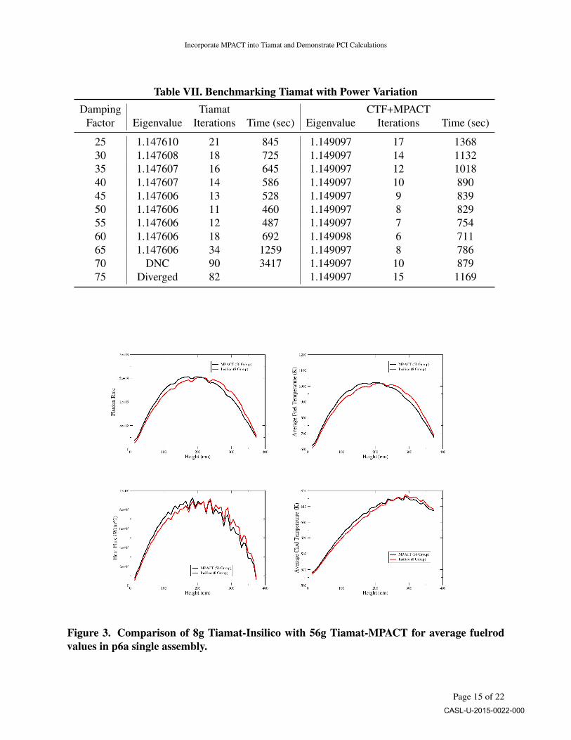
Table VII demonstrates that the damping factor does not significantly effect the eigenvalue butwill alter the convergence rate of the code. Tiamat converges for a wider range of damping factorsand in fewer iterations than CTF+MPACT. However, the execution times for CTF+MPACT, when itconverges, are consistently less than Tiamat.
5 DEMONSTRATION TIAMAT WITH MPACT
Large single- and multi-assembly calculations are in the queue on EOS and will be incorporatedinto a later revision of this report.
The AMA benchmark progression problem P6a was used to simulate a single assembly forTiamat-MPACT. This was compared to simulations from the L1 milestone performed with Tiamat-Insilico in Figure 3.
6 DEPLETION ALGORITHM SPECIFICATION
A challenging aspect of this problem is that the different physics associated with these codesare strongly coupled and nonlinear. By strongly-coupled we mean that the quantities calculated in
Page 14 of 22CASL-U-2015-0022-000
Incorporate MPACT into Tiamat and Demonstrate PCI Calculations
Table VII. Benchmarking Tiamat with Power VariationDamping Tiamat CTF+MPACT
Factor Eigenvalue Iterations Time (sec) Eigenvalue Iterations Time (sec)
25 1.147610 21 845 1.149097 17 136830 1.147608 18 725 1.149097 14 113235 1.147607 16 645 1.149097 12 101840 1.147607 14 586 1.149097 10 89045 1.147606 13 528 1.149097 9 83950 1.147606 11 460 1.149097 8 82955 1.147606 12 487 1.149097 7 75460 1.147606 18 692 1.149098 6 71165 1.147606 34 1259 1.149097 8 78670 DNC 90 3417 1.149097 10 87975 Diverged 82 1.149097 15 1169
Figure 3. Comparison of 8g Tiamat-Insilico with 56g Tiamat-MPACT for average fuelrodvalues in p6a single assembly.
Page 15 of 22CASL-U-2015-0022-000

K. Clarno and R. Pawlowski
each physics component and passed to the other have a significant impact on the physical quantitiescomputed in other physics components. To solve the coupled system, block Jacobi and blockGauss-Seidel fixed-point (FP) iteration strategies are provided through PIKE.
In traditional PCI analyses, the power distributions, ramping rates, and coolant (or clad)boundary conditions are defined in the input to the fuel-performance code. For ?nominal operation?PCI analyses (as with FRAPCON), the boundary conditions are based on independently executedmulti-cycle, quasi-static, core simulator results. For ?transient? PCI analyses, the fuel performancecode boundary conditions are based on results from a transient core simulator analysis, whichused an initial state that was based on the results from a quasi-static core-simulator solution. Thissection is not intended to define, or even propose, the approach that CASL will take in determiningthe methodology used for nominal or transient PCI analyses, but simply to begin a discussion ofpotential use-cases for Tiamat. We first review the algorithm that was used for the initial ramp tofull power (Section 6.1) and then propose an algorithm (Section 6.2) for nominal operation PCIanalysis of a first cycle core. In Section 6.3, we discuss the challenges and potential of extendingthis to multi-cycle analyses using either Tiamat alone or in conjunction with the core simulator.
6.1 SINGLE-RAMP
The overall execution is to perform an initialization phase to bring all codes to hot full power(HFP) conditions and then perform the fixed-point coupled iterations between the codes at HFP untilconvergence for one or more time steps. In order to apply a linear power ramping to BisonCASL,an estimate of HFP conditions are needed. There are currently three choices to obtain this estimate.The first is to perform several iterations of CTF+MPACT (not coupled to BisonCASL) at HFPconditions. The second choice is to restart from a converged run using restart data saved on thecoupling mesh. The third choice is to use a combination of the first two choices ? restart closeto the solution and perform a few iterations of CTF+MPACT. The following describes the startupprocedure.
1. Model transition from cold, zero-power (CZP) to hot, zero-power (HZP) in Bison-CASL.
• BisonCASL transient for 100 seconds
• Linear ramp of clad surface temperature from 20 to 293 C
• Power in every pin is zero.
2. Estimate the final (HFP) state clad surface temperature and power.
• Read restart file and/or perform several iterations of CTF+MPACT to estimate HFPconditions.
• Estimate of clad surface temperature for each pin at each axial node
• Estimate of power distribution for each pin and axial node.
Page 16 of 22CASL-U-2015-0022-000

Incorporate MPACT into Tiamat and Demonstrate PCI Calculations
3. Model the thermo-mechanical changes in the fuel from HZP to the estimated HFP
• BisonCASL transient for 48 hours.
• Linear ramp of clad surface temperature from 293 C to estimated HFP value (Step 1).
• Linear ramp of power distribution from zero to estimated HFP value (Step 1).
4. Model the final (HFP) state with CTF+MPACT+BisonCASL
• Subcycle all three codes using a fixed-point iteration scheme for each time step.
• Converge MPACT with pin temperatures from BisonCASL and coolant conditions fromCTF
• Converge CTF to steady-state with a BisonCASL heat flux using a series of time-steps
• Model a single time-step in BisonCASL at each coupled iteration using power fromMPACT and clad surface temperature from CTF
The numerical coupling of all three codes for the HFP conditions leverage the algorithms withinPIKE and include parallel, block Jacobi and parallel, block Seidel iterations schemes. The algorithmsare discussed in [6]. There are nuances within this general approach that were enhanced as part ofthis milestone and are discussed in more detail in Section 3.
6.2 FIRST-CYCLE, QUASI-STATIC
For freshly-fueled core, such as Cycle 1 of Watts Bar 1, the as-manufactured initial state ofthe fuel can be well-defined with a VERA input file. For nominal operation of a single cyclewith no rapid transients, the core simulator, with the CTF fuel model, can provide an estimatedrepresentation of the smooth temporal variations in the power and clad surface temperature usinglarge, quasi-static time steps. Using the traditional approach, this could provide the input toBisonCASL to model the spatial and temporal variation of the power, coolant pressure, and coolant(or clad surface) temperature to estimate PCI. However, differences in the fuel modeling betweenCTF and BisonCASL will account in some loss of accuracy. If Tiamat were capable of modelingthe first cycle, the error in the traditional approach could be estimated and minimized.
In stand-alone BisonCASL, there are generally many small, logarithmicly-increasing, time-steps are used to accurately model the transition due to changes in the power or coolant condi-tions. Similarly, MPACT models isotopic depletion between quasi-static states with many small,logarithmicly-increasing, time steps. As noted in Section 2.2, Tiamat could solve the coupledproblem for each of the small time steps that are required by BisonCASL and isotopic depletion.However, experience with core-simulators has shown that this is generally not required for theaccuracy needed from a core simulator. Therefore, as a first step, we propose an algorithm thatis consistent with the traditional core-simulator algorithm (coupled physics solutions at a set ofpre-defined, large, time steps) that preserves the accuracy required by both depletion and fuelperformance using many, logarithmicly-increasing, time steps. The single ramp to HFP described in
Page 17 of 22CASL-U-2015-0022-000
K. Clarno and R. Pawlowski
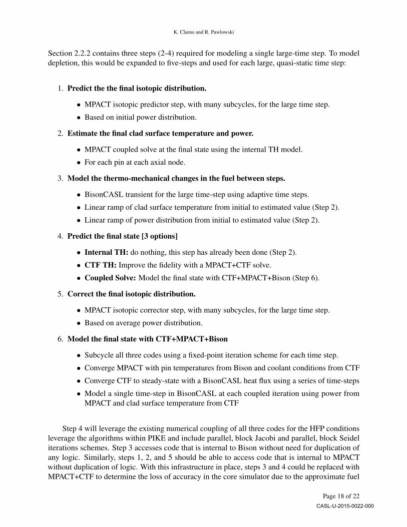
Section 2.2.2 contains three steps (2-4) required for modeling a single large-time step. To modeldepletion, this would be expanded to five-steps and used for each large, quasi-static time step:
1. Predict the the final isotopic distribution.
• MPACT isotopic predictor step, with many subcycles, for the large time step.
• Based on initial power distribution.
2. Estimate the final clad surface temperature and power.
• MPACT coupled solve at the final state using the internal TH model.
• For each pin at each axial node.
3. Model the thermo-mechanical changes in the fuel between steps.
• BisonCASL transient for the large time-step using adaptive time steps.
• Linear ramp of clad surface temperature from initial to estimated value (Step 2).
• Linear ramp of power distribution from initial to estimated value (Step 2).
4. Predict the final state [3 options]
• Internal TH: do nothing, this step has already been done (Step 2).
• CTF TH: Improve the fidelity with a MPACT+CTF solve.
• Coupled Solve: Model the final state with CTF+MPACT+Bison (Step 6).
5. Correct the final isotopic distribution.
• MPACT isotopic corrector step, with many subcycles, for the large time step.
• Based on average power distribution.
6. Model the final state with CTF+MPACT+Bison
• Subcycle all three codes using a fixed-point iteration scheme for each time step.
• Converge MPACT with pin temperatures from Bison and coolant conditions from CTF
• Converge CTF to steady-state with a BisonCASL heat flux using a series of time-steps
• Model a single time-step in BisonCASL at each coupled iteration using power fromMPACT and clad surface temperature from CTF
Step 4 will leverage the existing numerical coupling of all three codes for the HFP conditionsleverage the algorithms within PIKE and include parallel, block Jacobi and parallel, block Seideliterations schemes. Step 3 accesses code that is internal to Bison without need for duplication ofany logic. Similarly, steps 1, 2, and 5 should be able to access code that is internal to MPACTwithout duplication of logic. With this infrastructure in place, steps 3 and 4 could be replaced withMPACT+CTF to determine the loss of accuracy in the core simulator due to the approximate fuel
Page 18 of 22CASL-U-2015-0022-000

Incorporate MPACT into Tiamat and Demonstrate PCI Calculations
model. In the initial implementation, Bison and MPACT will have some inconsistent data becausethey both perform isotopic depletion internally. MPACT computes the power and Tiamat convertsthat to a fission rate, which is used by Bison for limited isotopic depletion and fission gas generation.In the future, DTK can be used to transfer isotopic data between Bison and MPACT. However,substantial clarification will be required because of nuances such as the mesh resolution needs ofBison and expectations on MPACT to consistently accounting for fission gas released from the fuel.
6.3 MULTI-CYCLE, QUASI-STATIC
For multi-cycle analyses with Tiamat, there are several approaches that could be considered.At this point, we document these for discussion purposes alone. The traditional approach would beto model the multiple cycles using VERA-CS to provide boundary conditions for the full lifetime ofthe single fuel pin of interest, which would be modeled with a stand-alone Bison calculation. Notethat the fuel pin of interest would have a PCI during a particular cycle of interest; the fuel pin ofinterest is part of a fuel assembly of interest that was first introduced to the reactor in the first cycleof the assembly of interest.
The challenge for multi-cycle modeling with BisonCASL is associated with the book-keepingrelated to the history of the fuel rods. Modeling fuel shuffling is relatively straight forward whenusing the CTF or internal TH models of MPACT if the assemblies are all identical because thefuel material models in both codes are independent of the prior operating history. Therefore, whenassemblies are shuffled the entire infrastructure remains and no changes are required to track whichpin moved to which location. However, BisonCASL has many components that are tightly correlatedwith the previous operation of the fuel; of particular importance are the structural mechanics andfission gas release history. Therefore, the driving code (either MPACT or Tiamat) would need tokeep track of the location of each pin and each assembly. Because Tiamat leverages DTK for thecoupling, this changes is very easy based on a simple adjustment of the centerline of each pin.Within MPACT, this may require substantial work, but it hasn’t been investigated significantly.
More integrated approaches that may be considered include:
• Model the entire reactor for the entire history, including the cycle of interest, with Tiamat.(prohibitively expensive)
• Model the entire reactor for all cycles up to the first cycle of the assembly of interest withMPACT; model the entire reactor for all remaining cycles with Tiamat. For every pin in thefirst cycle of the assembly of interest, model the full history of all fuel pins using stand-aloneBisonCASL to define the initial conditions for Tiamat. (very expensive with challengingBisonCASL restart file management)
• Model the entire reactor for all cycles up to the cycle of interest with MPACT; model theentire reactor for the cycle of interest using Tiamat. For every pin in the cycle of interest,model the full history of all fuel pins using stand-alone Bison to define the initial conditionsfor Tiamat. (less expensive, but still very challenging bookkeeping)
Page 19 of 22CASL-U-2015-0022-000

K. Clarno and R. Pawlowski
• Model only the fuel pin of interest with a standard BisonCASL input and model the rest ofthe pins using a simplified fuel model. The simplified model could be BisonCASL with onlylinear heat transfer enabled, the CTF fuel model, or the MPACT internal TH model.
The final bullet is likely the long-term solution to managing multi-cycle PCI analysis of nominaloperating conditions for CASL.
For Phase 2 of CASL, Tiamat will not be modeling transients. The PCI aspects of transientswill be modeled with BisonCASL with input from VERA-CS.
7 TESTING REQUIRED FOR THE DEPLETION SPECIFICATION
During PoR-10, we will begin to implement the first-cycle depletion capability. At this point,we recognize that additional interfaces in MPACT will be required to interface with it in this format.
MPACT currently has no multi-state, depletion, or shuffling tests using the VERA input.
The existing accessors/functions include:
initialize - initialize
setup - create data structures
finalize - clean data structures
shield - sub-group cross section shielding
computeXS - recompute cross sections
solve - solve the eigenvalue problem with fixed cross sections
init - initialize the data structures for coupling
clear - clear the data structures for coupling
setTH - set TH data for use in cross sections
We would need the following additional functions for execution:
runPredictorStep - isotopic depletion predictor step
runCoupledSolve - single solve with all internal feedbacks
runCorrectorStep - isotopic depletion corrector step
Page 20 of 22CASL-U-2015-0022-000
Incorporate MPACT into Tiamat and Demonstrate PCI Calculations
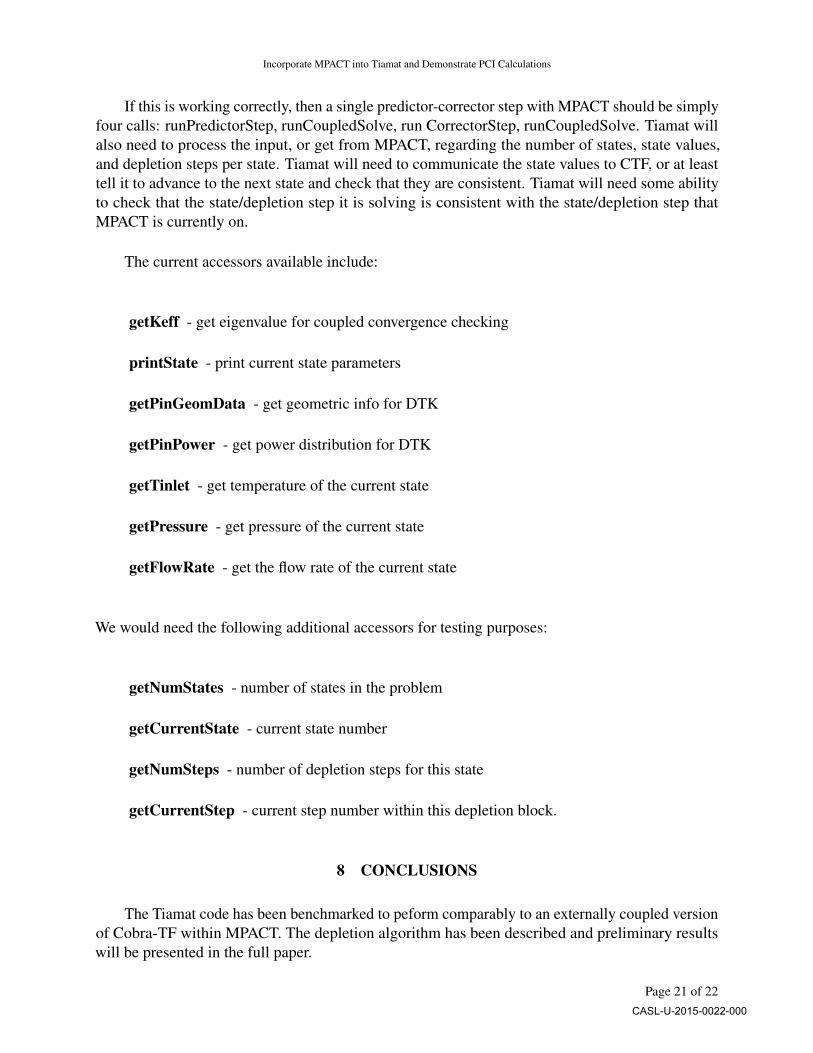
If this is working correctly, then a single predictor-corrector step with MPACT should be simplyfour calls: runPredictorStep, runCoupledSolve, run CorrectorStep, runCoupledSolve. Tiamat willalso need to process the input, or get from MPACT, regarding the number of states, state values,and depletion steps per state. Tiamat will need to communicate the state values to CTF, or at leasttell it to advance to the next state and check that they are consistent. Tiamat will need some abilityto check that the state/depletion step it is solving is consistent with the state/depletion step thatMPACT is currently on.
The current accessors available include:
getKeff - get eigenvalue for coupled convergence checking
printState - print current state parameters
getPinGeomData - get geometric info for DTK
getPinPower - get power distribution for DTK
getTinlet - get temperature of the current state
getPressure - get pressure of the current state
getFlowRate - get the flow rate of the current state
We would need the following additional accessors for testing purposes:
getNumStates - number of states in the problem
getCurrentState - current state number
getNumSteps - number of depletion steps for this state
getCurrentStep - current step number within this depletion block.
8 CONCLUSIONS
The Tiamat code has been benchmarked to peform comparably to an externally coupled versionof Cobra-TF within MPACT. The depletion algorithm has been described and preliminary resultswill be presented in the full paper.
Page 21 of 22CASL-U-2015-0022-000

K. Clarno and R. Pawlowski
9 ACKNOWLEDGMENTS
This manuscript has been authored by the Oak Ridge National Laboratory, managed by UT-Battelle LLC under Contract No. DE-AC05-00OR22725 with the US Department of Energy. TheUS Government retains and the publisher, by accepting the article for publication, acknowledgesthat the US Government retains a nonexclusive, paid-up, irrevocable, worldwide license to publishor reproduce the published form of this manuscript, or allow others to do so, for US Governmentpurposes. Sandia National Laboratories is a multi-program laboratory managed and operatedby Sandia Corporation, a wholly owned subsidiary of Lockheed Martin Corporation, for theU.S. Department of Energy’s National Nuclear Security Administration under contract DE-AC04-94AL85000. This research was supported by the Consortium for Advanced Simulation of LightWater Reactors (www.casl.gov), an Energy Innovation Hub (http://www.energy.gov/hubs) forModeling and Simulation of Nuclear Reactors under U.S. Department of Energy Contract No.DE-AC05-00OR22725. This research used resources of the Oak Ridge Leadership ComputingFacility at the Oak Ridge National Laboratory, which is supported by the Office of Science of theU.S. Department of Energy under Contract No. DE-AC05-00OR22725.
10 REFERENCES
[1] R. P. Pawlowski, K. T. Clarno, and R. O. Montgomery, “Demonstrate Integrated VERA-CS forthe PCI Challenge Problem,” CASL-I-2014-0153-000, Oak Ridge National Laboratory (2014).
Page 22 of 22CASL-U-2015-0022-000