inch-pound .))))))))))))- mil-hdbk-1003/3 15 november 1995
TRANSCRIPT

+)))))))))))), * INCH-POUND * .))))))))))))- MIL-HDBK-1003/3 15 NOVEMBER 1995
MILITARY HANDBOOK
HEATING, VENTILATING, AIR CONDITIONING,
AND DEHUMIDIFYING SYSTEMS
AMSC N/A AREA FACR
DISTRIBUTION STATEMENT A. APPROVED FOR PUBLIC RELEASE: DISTRIBUTION IS UNLIMITED.

MIL-HDBK-1003/3
ABSTRACT
This handbook is for the use of design and construction of NavalFacilities heating, ventilating, air conditioning, anddehumidifying systems.
ii
FOREWORD
This handbook is one of a series developed for instruction on thepreparation of Navy facilities engineering and design criteriadocuments. This handbook uses, to the maximum extent feasible,national and institute standards in accordance with NavalFacilities Engineering Command (NAVFACENGCOM) policy. Do notdeviate from this handbook for NAVFACENGCOM criteria withoutprior approval of NAVFACENGCOM Criteria Office, Code 15.
Recommendations for improvement are encouraged from within theNavy, other Government agencies, and the private sector andshould be furnished on the DD Form 1426 provided inside the backcover to Commander, Naval Facilities Engineering Command,Mr. Tom Harris, Code 15, 1510 Gilbert Street, Norfolk, VA23511-2699; phone commercial (804) 322-4206, facsimile machine(804) 322-4416.
THIS HANDBOOK SHALL NOT BE USED AS A REFERENCE DOCUMENT FORPROCUREMENT OF FACILITIES CONSTRUCTION. IT IS TO BE USED IN THEPURCHASE OF FACILITIES ENGINEERING STUDIES AND DESIGN (FINALPLANS, SPECIFICATIONS, AND COST ESTIMATES). DO NOT REFERENCE ITIN MILITARY OR FEDERAL SPECIFICATIONS OR OTHER PROCUREMENTDOCUMENTS.
iii

MIL-HDBK-1003/3
MECHANICAL ENGINEERING CRITERIA MANUALS
Criteria Manual Title PA
MIL-HDBK-1003/1 Plumbing (Proposed) WESTDIV
MIL-HDBK-1003/2 Incinerators WESTDIV
DM-3.04 Refrigeration Systems for ColdStorage WESTDIV
MIL-HDBK-1003/5 Compressed Air and Vacuum Systems(Proposed) WESTDIV
MIL-HDBK-1003/6 Central Heating Plants NFESC
MIL-HDBK-1003/7 Fossil Fuel Power Plants (Proposed) NFESC
MIL-HDBK-1003/8A Exterior Distribution of Utility Steam, High Temperature Water (HTW), Chilled Water (CHW), Fuel Gas and Compressed Air NORTHDIV
DM-3.09 Elevators, Escalators, Dumbwaiters, Access Lifts, and Pneumatic Tube Systems WESTDIV
DM-3.10 Noise and Vibration Control forMechanical Equipment ARMY
MIL-HDBK-1003/11 Diesel Electric Generating Plants NAVFAC
MIL-HDBK-1003/12 Boiler Controls NAVFAC
MIL-HDBK-1003/13 Solar Heating of Buildings and Domestic Hot Water NFESC
DM-3.14 Power Plant Acoustics ARMY
DM-3.15 Air Pollution Control Systems for Boilers and Incinerators NFESC
MIL-HDBK-1003/17B Industrial Ventilating Systems NAVFAC
MIL-HDBK-1003/19 Design Procedures for Passive Solar Buildings NFESC
MIL-HDBK-1008B Fire Protection for FacilitiesEngineering Design and Construction NAVFAC
iv

MIL-HDBK-1003/3
HEATING, VENTILATING, AIR CONDITIONING, AND DEHUMIDIFYING SYSTEMS
CONTENTS
PageSection 1 INTRODUCTION 1.1 Scope...................................... 1 1.2 Cancellation............................... 1 1.3 Purpose.................................... 1 1.4 Policy..................................... 1 1.5 Referenced Criteria........................ 2 1.6 Safety..................................... 2
Section 2 GENERAL 2.1 Load and Energy Calculations............... 4 2.1.1 Load Calculation Procedures................ 4 2.1.1.1 Load Calculation Form...................... 4 2.1.1.2 Design Conditions.......................... 4 2.1.1.3 Variable Air Volume (VAV) Systems.......... 4 2.1.1.4 Outdoor Air Load........................... 4 2.1.2 Energy Analysis............................ 4 2.1.2.1 Building Orientation....................... 4 2.1.2.2 Architectural Features..................... 4 2.1.2.3 Mechanical System Selection................ 5 2.1.2.4 Electrical Lighting System Selection (Daylighting) 5 2.1.2.5 Special Energy Conservation Features....... 5 2.2 Equipment Selection........................ 6 2.2.1 General.................................... 6 2.2.2 Heating Equipment.......................... 6 2.2.2.1 Boiler Sizing.............................. 6 2.2.2.2 Boiler Fuel................................ 7 2.2.2.3 Auxiliary Equipment........................ 7 2.2.2.4 Terminal Equipment......................... 7 2.2.3 Cooling Equipment.......................... 7 2.2.3.1 General......................... .......... 8 2.2.3.2 Packaged DX Equipment...................... 8 2.2.3.3 Central Chilled Water Equipment............ 8 2.2.3.4 Auxiliary Equipment - Cooling.............. 8 2.2.4 Ventilation Equipment...................... 9 2.2.4.1 General.................................... 10 2.2.4.2 Humid Climates............................. 10 2.2.4.3 Engineered Smoke Control System............ 10 2.2.5 Humidification Equipment................... 10 2.2.5.1 General.................................... 10 2.2.5.2 Steam Humidifiers.......................... 10 2.2.5.3 Atomizing Humidifiers...................... 10 2.2.6 Temperature Controls....................... 10 2.2.6.1 General.................................... 10
v

MIL-HDBK-1003/3
Page 2.2.6.2 Direct Digital Controls (DDC).............. 11 2.2.6.3 Temperature Control Drawings and
Specifications............................. 11 2.2.6.4 Automatic Control Valves................... 11 2.2.7 Energy Monitoring and Control System (EMCS) 11 2.2.8 Instrumentation............................ 11 2.2.8.1 Indicating Instruments..................... 11 2.2.8.2 Recording Instruments...................... 11 2.2.8.3 Combination Instrument and Controls........ 13 2.2.8.4 Multi-Point Remote Indicators.............. 13 2.2.8.5 Control Board.............................. 13 2.2.8.6 Desired Instrumentation Characteristics.... 13 2.2.9 Metering................................... 14 2.2.10 Piping Systems............................. 14 2.2.10.1 Sizing..................................... 14 2.2.10.2 Pipe Expansion............................. 14 2.2.11 Duct System Design ........................ 14 2.2.11.1 HVAC Systems............................... 14 2.2.11.2 Restriction on Use of Ductwork............. 15 2.2.12 Industrial Ventilation and Exhaust Systems. 15 2.3 Noise and Vibration Control................ 16 2.4 System and Equipment Performance........... 16 2.4.1 Cooling Systems............................ 16 2.4.1.1 Central Air Conditioning Systems........... 16 2.4.1.2 Unitary Air Conditioning Systems........... 16 2.4.1.3 Room Air Conditioning Units................ 17 2.4.1.4 Built-up Systems........................... 17 2.4.2 Heating Systems............................ 17 2.4.2.1 Individual Heating Plants.................. 17 2.4.2.2 Central Heating Plants..................... 18 2.4.2.3 Snow Melting Systems....................... 18 2.4.3 All-Air Systems............................ 18 2.4.3.1 Constant-Volume Systems.................... 18 2.4.3.2 Variable Air Volume (VAV) Systems.......... 19 2.4.3.3 Economizer Cycle........................... 19 2.4.4 Duct, Pipe, and Equipment Insulation....... 19 2.4.5 Computer Programs for Load Calculation..... 19 2.5 Mechanical Room Ventilation................ 20 2.5.1 Self-Contained Breathing Apparatus (SCBA)....20 2.6 Radon Mitigation Systems................... 21
Section 3 APPLICATIONS 3.1 General.................................... 23 3.2 All Building Types......................... 23 3.3 Air Force Projects......................... 23 3.4 Tropical Engineering....................... 23 3.5 Electronic Facilities...................... 23 3.6 Air Cargo Terminal......................... 29
vi

MIL-HDBK-1003/3
Page 3.7 Aircraft Line Operations Building.......... 29 3.8 Photographic Building...................... 29 3.9 Naval Air Station Control Tower............ 30 3.10 Liquid Oxygen and Nitrogen Facilities...... 30 3.11 Maintenance Facilities for Ammunition,
Explosives, and Toxics..................... 30 3.12 General Maintenance Facilities............. 30 3.13 Hospital, Dental, and Medical Facilities... 31 3.14 Family Housing............................. 31 3.15 Bachelor Enlisted Quarters................. 31 3.16 Bachelor Officer Quarters.................. 32 3.17 Industrial Ventilation..................... 32 3.18 Kitchen Ventilation........................ 32 3.18.1 Kitchen Equipment Exhaust Hoods............ 32 3.18.2 Exhaust Systems............................ 32 3.18.3 Fire Protection............................ 33 3.18.4 Calculation of Exhaust Hood Air Volume Rate 33 3.18.5 Exhaust Hood Heat Recovery................. 35 3.18.6 Air Curtains............................... 36 3.19 Laundries.................................. 36
Section 4 INFORMATION REQUIRED ON DRAWINGS 4.1 General................................... 38 4.1.1 Identification of Drawings................ 38 4.1.2 Equipment Schedules....................... 38 4.1.3 Duct Pressure Classifications............. 38 4.1.4 Riser Diagrams............................ 38 4.1.5 Controls.................................. 38 4.1.6 Maintainability........................... 39 4.1.7 Symbols and Abbreviations................. 40 4.1.7.1 General................................... 40 4.1.7.2 Specifics................................. 40 4.1.8 Building Column Lines and Room Names...... 40
Section 5 LOAD CALCULATIONS 5.1 General................................... 41 5.2 Heating Load.............................. 41 5.2.1 Transmission.............................. 41 5.2.2 Infiltration and Ventilation.............. 41 5.2.3 Total Heating Load........................ 42 5.3 Cooling Load.............................. 42 5.3.1 Transmission.............................. 42 5.3.1.1 Walls and Roof............................ 42 5.3.1.2 Glass..................................... 42 5.3.2 Infiltration and Ventilation.............. 43 5.3.3 Internal Loads............................ 44 5.3.3.1 People Loads.............................. 44 5.3.3.2 Lights and Equipment...................... 44
vii

MIL-HDBK-1003/3
PageSection 6 AIR DISTRIBUTION 6.1 Duct Design for HVAC Systems............... 46 6.1.1 Sizing General............................. 46 6.1.2 Equal Friction Method Sizing............... 46 6.1.3 Ductwork General........................... 46 6.1.3.1 Round Ducts................................ 46 6.1.3.2 Rectangular Ducts.......................... 46 6.1.3.3 Access Doors............................... 48 6.1.3.4 Flexible Ducts............................. 48 6.1.3.5 Rooftop Ductwork........................... 48 6.1.3.6 Glass Fiber Ductwork....................... 48 6.1.3.7 Balancing Dampers for HVAC................. 48 6.1.3.8 Fire Dampers and Smoke Dampers............. 50 6.1.3.9 Fan Systems Effect Factors................. 51 6.1.4 Ductwork Details........................... 51 6.1.4.1 Branches................................... 51 6.1.4.2 Elbows..................................... 51 6.1.4.3 Offsets and Transmissions.................. 51 6.1.5 Testing and Balancing...................... 51 6.2 Fans for HVAC Systems...................... 51 6.2.1 Fan Selection.............................. 51 6.2.1.1 Major Types of HVAC Fans................... 51 6.2.1.2 Size....................................... 51 6.2.1.3 Sound Rating............................... 52 6.2.1.4 Static Pressure Requirement................ 52 6.2.1.5 VAV Fan Selection.......................... 59 6.3 Economizer Cycle........................... 59 6.4 Terminal Equipment......................... 59 6.5 Louvers.................................... 60 6.6 Filters for VAV Systems.................... 60 6.7 Access for Inspection and Maintenance...... 61 6.8 VAV System Design.......................... 62 6.9 Ductwork Pressure-Velocity Classification.. 62
Section 7 PIPING SYSTEMS 7.1 General.................................... 65 7.1.1 Piping Design Factors...................... 65 7.1.2 Pipe Friction Loss......................... 65 7.1.3 System Pressure Loss....................... 65 7.1.4 Piping Layouts............................. 65 7.1.5 Expansion.................................. 65 7.1.6 Expansion Loop............................. 66 7.1.7 Packing-Type Expansion and Ball Joints..... 66 7.1.8 Bellows Expansion Joints................... 66 7.1.9 Supports and Anchors....................... 66 7.1.10 Flexible Hose.............................. 68 7.2 Water Systems.............................. 69 7.2.1 General.................................... 69
viii

MIL-HDBK-1003/3
Page 7.2.1.1 Exterior Water Piping Design............... 69 7.2.1.2 Water Velocity............................. 69 7.2.1.3 Water Treatment............................ 69 7.2.1.4 Pipe Sizing................................ 70 7.2.1.5 Valve and Fitting Pressure Drops........... 70 7.2.1.6 Return Arrangements........................ 70 7.2.1.7 Air Vents.................................. 70 7.2.2 Hot Water Heating Systems.................. 70 7.2.2.1 Hot Water Piping........................... 70 7.2.2.2 Hot Water Coils............................ 70 7.2.2.3 Expansion Tanks and Air Separator.......... 73 7.2.2.4 Domestic Hot Water Generator............... 74 7.2.2.5 Heat Exchangers............................ 74 7.2.2.6 Pumps...................................... 79 7.2.3 Chilled Water.............................. 80 7.2.3.1 Pipe Size.................................. 80 7.2.3.2 Coils...................................... 80 7.2.3.3 Expansion Tanks............................ 80 7.2.3.4 Pumps...................................... 80 7.3 Steam...................................... 81 7.3.1 General.................................... 81 7.3.2 Low Pressure Steam Systems................. 81 7.3.2.1 Pipe Sizing................................ 81 7.3.3 High Pressure Steam Systems................ 81 7.3.3.1 Pipe Sizing................................ 81 7.3.3.2 Boiler..................................... 89 7.3.3.3 Heat Exchanger............................. 89 7.3.3.4 Steam Pressure Regulating Valves........... 89 7.3.3.5 Condensate Pumps and Flash Tank.............92 7.3.3.6 Steam Coils - General...................... 92 7.3.3.7 Steam Traps................................ 92 7.3.4 Boilers.................................... 92 7.3.5 Freezing of Steam Coils - General.......... 97 7.3.5.1 Freezing Due to Air Stratification......... 97 7.3.5.2 Freezing Due to Build-up of Condensate in
the Coil................................... 98 7.3.6 Refrigerant Piping.........................101 7.3.6.1 General....................................101 7.3.6.2 Sizing.....................................101 7.3.6.3 Arrangement................................101
Section 8 CONTROLS AND INSTRUMENTATION 8.1 General Requirements.......................104 8.1.1 Choice of Controls.........................104 8.1.1.1 A Guide to Choose Control Systems..........104 8.1.1.2 Factors to Select Control Systems..........104 8.1.2 Designing DDC Systems......................105
ix

MIL-HDBK-1003/3
Page 8.2 Standard Sequences of Operations...........107 8.2.1 General Requirements.......................107 8.2.2 Operation of HVAC System...................107 8.2.3 Operation of Outside Air, Return Air, and Exhaust (Relief) Air Dampers...............107 8.2.4 Operation of Filtration System.............107 8.2.5 Operation of Freeze Protection.............108 8.2.6 Operation of Smoke Detectors...............108 8.2.7 Operation of Chilled Water Coil Discharg8
Control....................................108 8.2.8 Operation of Preheat Coil Control..........108 8.2.9 Operation of Heating Coil Control..........108 8.2.10 Operation of Space Control (Single Zone
Unit)......................................108 8.2.11 Operation of Space Control (Multizone
Unit)......................................109 8.2.12 Operation of Space Control (VAV Terminal
Unit - Pressure Dependent).................109 8.2.13 Operation of Supply Duct Pressure Control..109 8.3 Single Zone Unit Sequence of Operation.....109 8.4 Multizone Unit Sequence of Operation.......110 8.5 Variable Air Volume (VAV) Unit Sequence of
Operation..................................119 8.6 Commissioning Procedures...................124 8.6.1 Functional Performance Test................124 8.6.2 Preparation for Acceptance Testing.........125 8.6.3 System Static Checkout.....................125 8.6.3.1 Observation................................125 8.6.3.2 Calibration................................125 8.6.3.3 Operation..................................126 8.6.4 System Dynamic Checkout....................126 8.6.4.1 Controller Manual-Tuning Procedure.........126 8.6.5 Procedures for Single Zone Control System..128 8.6.6 Procedures for Multizone Control System....130 8.6.7 Variable Air Volume (VAV) Control System...132
Section 9 EQUIPMENT LOCATION 9.1 General....................................135 9.2 Specific Considerations....................135 9.2.1 Noise......................................135 9.2.2 Access for Operations and Maintenance......135 9.2.3 Blocked Access.............................136 9.2.4 Emission of Odors..........................136 9.2.5 Cooling Tower Vibration....................136
Section 10 FUNDAMENTAL DRAWING DETAILS 10.1 General....................................137 10.2 Specifics..................................137
x

MIL-HDBK-1003/3
Page 10.2.1 System Diagrams and Schematics.............137 10.2.2 Equipment Schedules........................137 10.2.3 Riser Diagrams.............................137 10.2.4 Duct Pressure Classifications..............137 10.2.5 Symbols and Abbreviations..................137
Section 11 RULES OF THUMB GUIDANCE 11.1 General....................................144 11.2 Air Conditioning Capacity..................144 11.3 Heating Capacity...........................144 11.4 Moisture Loads.............................144 11.5 Chilled Water Circulation..................144 11.6 Hot Water..................................144 11.7 Condenser Water............................144 11.8 Steam......................................144 11.9 Condensate.................................144
Section 12 FIRE PROTECTION AND SMOKE CONTROL 12.1 General....................................146 12.2 System Design..............................146 12.3 Engineered Smoke Control System............147
APPENDICES
APPENDIX A Energy Conservation Methods................148APPENDIX B Engineered Smoke Control Systems...........172APPENDIX C Design Do's and Don'ts VAV Systems.........173APPENDIX D Variable Speed Drives (VFD’s)..............186
FIGURES
Figure 1 Floor Penetration for Sub-Slab Depressurization System.................... 22
2 Duct Sizing................................ 47 3 Damper Installation........................ 49 4 Fan System Effect Factors.................. 53 5 Duct Branches.............................. 54 6 Duct Branches.............................. 55 7 Duct Elbows................................ 56 8 Duct Offsets and Transitions............... 57 9 Hooked Louver Blade........................ 62 10 Duct Pressure Class Designation............ 64 11 Friction Loss for Water in Commercial
Steel Pipe (Schedule 40)................... 71 12 Friction Loss for Water in Copper Tubing (Types K, L, M)............................ 71 13 Friction Loss for Water in Plastic Pipe (Schedule 80).............................. 72
xi

MIL-HDBK-1003/3
Page 14 Closed Expansion Tank....................... 75 15 Diaphragm Expansion Tank.................... 76 16 Connections to Converter for Hot Water
Heating System.............................. 77 17 Domestic Hot Water Generator and Heating
Hot Water Boiler Piping Connection.......... 78 18 Chart for Flow Rate and Velocity of Steam
in Schedule 40 Pipe Based on Saturation Pressure of 30 psig......................... 85
19 Chart for Flow Rate and Velocity of Steam in Schedule 40 Pipe Based on Saturation Pressure of 50 psig......................... 86
20 Chart for Flow Rate and Velocity of Steam in Schedule 40 Pipe Based on Saturation Pressure of 100 psig........................ 87
21 Chart for Flow Rate and Velocity of Steam in Schedule 40 Pipe Based on Saturation Pressure of 150 psig........................ 88
22 PRV--Low Pressure........................... 90 23 Two Stage PRV............................... 91 24 Flash Tank and Duplex Condensate Pump Unit.. 93 25 Steam Coils................................. 94 26 Steam Tempering Coils....................... 95 27 Low Pressure Drip........................... 96 28 Boiler Connections.......................... 97 29 Air Stratification to Coil During Freeze-up
Conditions.................................. 99 30 Nonfreeze Coil Piping.......................100 31 Refrigerant Coil............................102 32 Compressor Piping...........................103 33 Control System Schematic for Single Zone
HVAC System XX..............................111 34 Control System Schematic for Multizone HVAC
System XX...................................115 35 Control System Schematic for VAV HVAC
System XX...................................121 36 Schematic Hot Water and Chilled Water
Balancing Diagram..........................138 37 Schematic Airflow Balancing Diagram.........139 38 Hot Water Riser Diagram.....................141 39 Notes on Drawing Riser Diagram..............142 40 Designating Duct Pressure Classes...........143 A1 Occupied/Unoccupied Hot Water Reset
Schedule....................................149 A2 Thermostat Setpoints Diagram................151 A3 Exhaust Air Heat Recovery With Rotary Air
Wheel.......................................154
xii

MIL-HDBK-1003/3
Page A4 Exhaust Air Heat Recovery With Counterflow
Pattern Static Heat Exchanger...............155 A5 Exhaust Air Heat Recovery with Crossflow
Pattern Static Heat Exchanger...............156 A6 Exhaust Air Heat Recovery Method With Heat
Pipe........................................157 A7 Exhaust Air Heat Recovery Method With
Runaround (Closed Loop) System..............158 A8 Exhaust Air Heat Recovery Method With
Runaround (Open Loop) System................160 A9 Heat of Light Recovery Method With Light
Troffer.....................................162 A10 Heat of Light Recovery Method With Induced
Air.........................................163 A11 Refrigeration Method Heat Recovery With
Conventional Refrigeration Machine Using Hot Water Coil..............................165
A12 Refrigeration Method Heat Recovery With Conventional Refrigeration Machine Using Refrigerant Coil............................166
A13 Refrigeration Method Heat Recovery With Internal Source Heat Pump...................167
A14 Refrigeration Method Heat Recovery With Single Bundle Condenser Water Circuit Method and Open Cooling Tower...............168
A15 Refrigeration Method Heat Recovery With Double Bundle Condenser Water Circuit Method......................................169
TABLES
Table 1 Recommended Air Conditioning Systems for Various Buildings........................... 3
2 Typical Instrument Applications............. 12 3 Applicable Criteria by Building Type........ 24 4 Thermal Currents Charts..................... 34 5 Safety Factor Chart......................... 35 6 Duty Group Chart............................ 35 7 Major Types of HVAC Fans.................... 58 8 Piping Materials............................ 67 9 Water Velocities............................ 69 10 Flow Rate in lb/h of Steam Schedule 40 Pipe. 82 11 Return Main and Riser Capacities for
Low-Pressure System, lb/h................... 83 12 Comparative Capacity of Steam Lines at
Various Pitches for Steam and Condensate Flowing in Opposite Directions.............. 83
xiii

MIL-HDBK-1003/3
Page 13 Steam Pipe Capacities for Low-Pressure
Systems..................................... 84 14 Common Types of Steam Traps................. 96 15 Equipment for Single Zone HVAC Control
System XX...................................113 16 Equipment for Multizone HVAC Control System
XX..........................................116 17 Equipment for VAV HVAC Control System XX....123 18 Typical Utility Fan Schedule................140 19 Sound Data Schedule.........................140 20 Cooling Coil Schedule.......................140 21 Air Conditioning Load Estimating Factors....145 22 Typical Load Breakdown of Dehumidified
Warehouse...................................145
REFERENCES ..............................................205
GLOSSARY ..............................................210
xiv

MIL-HDBK-1003/3
Section 1: INTRODUCTION
1.1 Scope. This handbook provides the Naval FacilitiesEngineering Command's policy and criteria for selection anddesign of heating, ventilating, air conditioning (HVAC), anddehumidifying systems as applied to Naval shore facilities.
1.2 Cancellation. This handbook cancels and supersedesNAVFAC design manual DM-3.03, Heating, Ventilation, AirConditioning and Dehumidifying Systems dated January 1987.
1.3 Purpose. Policy and criteria included in this handbookare provided to ensure quality and consistency in design of HVACand dehumidifying systems with minimum life cycle costs whichsatisfy functional and operational requirements of Navalfacilities and which provide a healthy and safe environment forfacility occupants.
1.4 Policy. Design of HVAC and dehumidifying systems shallbe in accordance with guidelines included in this handbook. Thematerial included in Sections 5 through 12 of this handbook isprovided for information and should be applied only as requiredto supplement the experience of the designer or design reviewer. NAVFAC policy is to select simple, easy to maintain and operate,HVAC systems designed based upon well established principles andconstructed of proven materials that satisfy space temperature,humidity, and indoor air quality (IAQ) requirements within energybudgets prescribed in MIL-HDBK-1190, Facility Planning and DesignGuide. Use the following procedures for selection and design ofHVAC systems:
a) Ensure that passive building design features, e.g.,building orientation, shading, building envelope, and insulationare optimized to reduce heating and cooling loads. Such passivetechniques reduce the requirement to use complex, maintenanceintensive, HVAC systems and equipment to meet the facility energybudget.
b) Place special emphasis on keeping HVAC systems,including controls, simple and easy to operate and maintain. Table 1, par. 2.4, and subparagraphs provide recommendations ontypes of air conditioning systems that should be considered forthe most common applications. The least complex of therecommended types should be selected based on functionalrequirements, ease of maintenance, and the design energy budget. For example, a system requiring extensive use of complexcontrolled devices and associated controls (e.g., complex heatrecovery systems) should only be considered when there are nopractical alternatives to obtain design energy budgets prescribed
1

MIL-HDBK-1003/3
in MIL-HDBK-1190. Otherwise, less complex, constant volumeunitary or air handler systems with zone control should be used.
c) Consider the level and responsiveness of maintenanceavailable at the customer's activity when selecting the HVACsystem. Success of the HVAC system is dependent upon acceptanceof the system by the local staff responsible for routinemaintenance. The staff should be able to understand theoperating principles and control logic. Maintenance of thesystem should not require skills and knowledge beyond theircapability. Ensure adequate space is provided for equipmentmaintenance and removal.
d) Consider the types of systems currently installedat an activity when making system selection for new facilities. Seek to provide consistency in system types unless a simpler,less maintenance intensive system can be used in the newfacility.
e) Specify training of activity personnel comparableto the degree of system and controls complexity provided andconsidering level of existing knowledge. In addition, providecustomer guidance relative to maintenance personnel (includinglevel of knowledge) or contract maintenance support required forthe HVAC system.
1.5 Referenced Criteria. The principal criteria referencesused in this handbook in order of priority are:
a) MIL-HDBK-1190.
b) NAVFAC design manuals and military handbooks. (Whenever a design manual is revised, the design manual isconverted to a military handbook.)
c) American Society of Heating, Refrigerating and Air-Conditioning Engineers, Inc. (ASHRAE) handbooks and standards. If a particular subject is not specifically addressed in thishandbook, ASHRAE criteria apply. For criteria that is notavailable in ASHRAE criteria, use the best available informationapplicable to the design requirement, including State and localcodes as applicable.
1.6 Safety. Design systems to meet requirements ofNational Fire Protection Association (NFPA) 90A, Standard for theInstallation of Air Conditioning and Ventilating Systems and NFPA90B, Standard for the Installation of Warm Air Heating and AirConditioning Systems and Department of Labor, 29 CFR Part 1910,Occupational Safety and Health Standards.
2

SYSTEMS (1)Building A B C D E F G H I
(2) (3) (3)Administration X X X X X X X X XApt. Houses - - X - - X X X -Auditoriums X X X X - X - X XBachelor Quarters X X X X X X X X XBakeries X X X X - - - X XChapels X X X X - X X X XCommunications X X X X - X X X XFamily Housing X - X - - X X X XGymnasiums X - - - - - - - XHangar (w/Lean-To) - - - - - X X - XHospitals X X X X - X X X XLaundries X X X X - - - X XSchools X X X X - X X X XShops X X X X - X - - XTheaters X X X X - X - - XTransmitters X X X X - X - - XWarehouses X - X - - - - - X
NOTES:
(1) System Types:
A - Single Duct System F - Fan Coil System B - Dual Duct System G - Induction System C - Multizone System H - Heat Pump System D - Variable Volume System I - Evap. Cooling System E - Perimeter Zone Air System
(2) Depends on building configuration.
(3) Depends on local weather conditions. Refer to MIL-HDBK-1190.
MIL-HDBK-1003/3
Table 1Recommended Air Conditioning Systems
for Various Buildings
3

MIL-HDBK-1003/3
Section 2: GENERAL
2.1 Load and Energy Calculations
2.1.1 Load Calculation Procedures. Refer to the ASHRAEHandbook, Fundamentals, for the acceptable method of performingload and energy calculations.
2.1.1.1 Load Calculation Form. Except for small buildings andminor renovation, less than 8000 square feet, loads should becalculated using a computer program which applies one of the methods in the ASHRAE Handbook, Fundamentals, Chapters 25 and 26. Simplified load calculation equations are reproduced in Section 5of this handbook. These simplified equations may be used onsmaller buildings with hand calculations.
2.1.1.2 Design Conditions. Select indoor and outdoor summerand winter design conditions in accordance with MIL-HDBK-1190. If a known micro-climate condition exists at the site, or ifbuilding site location is not shown in NAVFAC Publication P-89,Engineering Weather Data; consult the Navy design manager orproject leader (DM or PL) for instructions.
2.1.1.3 Variable Air Volume (VAV) Systems. For VAV systems,refer to Appendix C and ASHRAE Handbook, Fundamentals, for theacceptable method.
2.1.1.4 Outdoor Air Load
a) Infiltration. Use infiltration rates and themethod of calculation prescribed in ASHRAE Handbook,Fundamentals.
b) Ventilation. Use ventilation rates for IAQprescribed in ASHRAE Standard 62, Ventilation for AcceptableIndoor Air Quality and the method of calculation included inASHRAE Handbook, Fundamentals.
2.1.2 Energy Analysis
2.1.2.1 Building Orientation. Building orientation,fenestration, lighting, and geometry can have a profound effecton the building energy consumption, system selection, and zoning. Therefore, the HVAC designer should consult with the architectduring the early concept stage to optimize the overall design.
2.1.2.2 Architectural Features. The building mass, tightnessof construction, window treatment, occupancy zoning, and othercharacteristics can also impact the HVAC design. These features
4

MIL-HDBK-1003/3
need early consideration by the design disciplines to achieve thebest overall design concept. Consider using ENVSTD 24, aDepartment of Energy (DOE) envelope system performance compliancecalculation program to assist the architect and mechanicalengineer to evaluate the proposed facilities’ compliance withASHRAE Standard 90.1, Energy Efficient Design of New BuildingsExcept Low-Rise Residential Buildings, 10 CFR 435, and MIL-HDBK-1190 design energy targets. ENVSTD 24 is available onthe Construction Criteria Base (CCB) CD-ROM, or from ASHRAE orDOE.
2.1.2.3 Mechanical System Selection. Life cycle cost analysisof candidate systems should be used to determine the best systemselection within the parameters cited in par. 1.4. Includeelectrical demand charges as well as energy charges in theanalysis. Include rebates offered by the utility for use ofparticular forms of energy or types of equipment, such as icestorage or gas-fired adsorption chillers. Refer to MIL-HDBK-1190for guidance on the application of this procedure.
2.1.2.4 Electrical Lighting System Selection (Daylighting). The HVAC design engineer should assist in the evaluation ofdaylighting to ensure that electrical energy savings are notoffset by increased energy required by the HVAC system due toincreased heating and cooling loads. Consider using LTGSTD 24, aDOE lighting prescriptive and system performance compliancecalculation program to assist the architect and electrical andmechanical engineer to evaluate the proposed facilitiescompliance with ASHRAE Standard 90.1, 10 CFR Part 435, EnergyConservation Voluntary Performance Standards for Commercial andMulti-Family High Rise Residential Buildings, Mandatory for NewFederal Buildings and MIL-HDBK-1190 design energy targets. LTGSTD 24 is available on the CCB CD-ROM or from ASHRAE or DOE.
2.1.2.5 Special Energy Conservation Features. There remains acontinuing need to achieve energy conservation on Navy buildingsby optimization of new building designs, accurate controlsystems, retrofit of older buildings, and incorporation ofspecial energy conservation features wherever appropriate (asjustified by life cycle cost).
a) Solar. Include active and passive solar systemsfor space heating, for heating pools, and for domestic hot wateronly if economically feasible. A new economic analysis need notbe performed if a previous study on a similar facility withsimilar weather conditions is available.
b) Heat Recovery Techniques. Refer to Appendix A foran exposition of some of the various techniques of heat recovery.
5

MIL-HDBK-1003/3
Application of these techniques should only be considered whenrequired to meet the design energy budget and when operation andmaintenance are judged to be within the capability of localmaintenance personnel.
c) Thermal Storage. Due to the added complexity insystem operation and controls, only use thermal storage systemswhen required to meet the building energy budget and when provencost effective on a life cycle cost basis.
(1) Savings. Include demand charges, energycharges (energy cost may be lower when thermal storage is chargedoff peak), and savings in refrigeration equipment size reductionin the life cycle cost analysis. An electric rate structure witha high demand charge or with time-of-day metering rates providesthe best opportunity for savings on investment. Ensure that theanalysis includes the appropriate energy cost, e.g., billing forelectrical energy at a master meter vice the individual buildingmeter. If the station is master metered for consumers, additionof a single building may have no significant impact on the demandcharge, and additional energy used may be at the lowest availablerate. Other opportunities for savings include reduced cost forelectric service, increased efficiency of equipment operating atnight, and reduced cost for fire protection if water storage canbe integrated with thermal storage requirements.
(2) Equipment Selection. Packaged thermal storagesystems complete with controls are preferred over fieldfabricated systems.
2.2 Equipment Selection
2.2.1 General. Determine the type of heating and coolingsystem to be used by the computer energy and life cycle costanalysis as described in MIL-HDBK-1190, Chapter 8. ApplicableNavy design manuals and guide specifications provide guidance onthe recommended classes of equipment to be evaluated for theparticular application and size range.
2.2.2 Heating Equipment
2.2.2.1 Boiler Sizing. Refer to MIL-HDBK-1003/6, CentralHeating Plants and ASHRAE Handbook, Fundamentals for sizingboilers. Boiler sizing should consider:
a) Connected load, which includes the heating load,plus (where applicable) pipe loss and pickup, domestic hot water,process loads, and boiler plant auxiliaries.
6
MIL-HDBK-1003/3
b) Boiler plant's turndown ratio.
c) Provisions for future loads and standby foressential loads where applicable.
2.2.2.2 Boiler Fuel. Refer to MIL-HDBK-1003/6 for informationon how to select boiler fuel. Consider Navy criteria, fuel andlife-cycle costs, and Federal and local emission standards.
2.2.2.3 Auxiliary Equipment. Refer to MIL-HDBK-1003/6 and Navyguide specifications for information on types and sizing ofauxiliary equipment. Some notes on plant equipment are asfollows:
a) Centrifugal Pumps. Check the system net positivesuction head (NPSH) as well as the pump NPSH in the design. Inthe past, engineers frequently specified non-overloading typepumps. Today, pumping energy costs sometimes dictate other waysto arrange pump operating points. Do not oversize pumps. Referto the ASHRAE Handbook, Fundamentals and the Hydraulic Institutestandards for guidance on design of centrifugal pumping systems.
b) Non-Hermetic Motors. Refer to ASHRAE Handbook,Fundamentals; NFPA 70, National Electrical Code; and NationalElectrical Manufacturers Association (NEMA) standards forguidance on selecting motors and motor protective devices.
c) Hermetic Motors. Hermetic motors are used inrefrigeration compressors, selected by the equipmentmanufacturer, and protected as required by NFPA 70.
d) Engine and Turbine Drives. Consult ASHRAEHandbook, Fundamentals and applicable NFPA standards for designguidance on the application of engines and turbines used to drivecompressors, fire pumps, power generators, and co-generationequipment.
2.2.2.4 Terminal Equipment. Select and size terminal equipmentin accordance with ASHRAE Handbook, Fundamentals. Economic aswell as engineering considerations shall set the flow,temperature, temperature drop, pressure, and pressure drop forcentral plant equipment; distribution piping and fittings; andterminal equipment parameters. If new terminal equipment isadded to an existing plant, ensure that the new system piping andvalves will not disturb the proper operation of existingdistribution system.
2.2.3 Cooling Equipment
7

MIL-HDBK-1003/3
2.2.3.1 General. Select air cooled equipment on the basis ofentering air at 5 degrees F above the design temperature as givenin NAVFAC P-89 for roof mounted equipment and for equipment incorrosive environments.
2.2.3.2 Packaged DX Equipment. Multiple packaged DX equipmentshould only be used when it is shown to be life cycle costeffective for the application.
2.2.3.3 Central Chilled Water Equipment
a) Use only one chiller for comfort coolingapplications unless it becomes economical to split capacity. Mission requirements may dictate the use of multiple units withcapacities determined by critical loads. Obtain approval for theuse of multiple units from the engineering field division (EFD)or engineering field activity (EFA).
b) Size units on the basis of acceptable refrigerantsspecified in NAVFAC guide specification (NFGS)-15652, CentralRefrigeration Equipment for Air Conditioning. Do not userefrigerants with an ozone depletion potential (ODP) greater than0.05 or a global warming potential (GWP) greater than 0.34.
c) Use centrifugal or rotary screw compressor chillersfor capacities greater than 120 tons.
d) Though air cooled chillers are less efficient thanwater cooled chillers, air cooled chillers require lessmaintenance; this should be a consideration in the selection.
e) Water treatment of cooling towers and evaporativecondensers should be carefully considered. Continuous bleedingor dumping of water treated with chemicals to the sanitary orstorm sewer may be prohibited. Check with the localenvironmental program manager for use of wastewater and sanitarysewer systems.
2.2.3.4 Auxiliary Equipment - Cooling
a) Condenser Heat Rejection. Heat can be rejectedfrom a condensing refrigerant to atmosphere with an evaporativecondenser, with a water-cooled condenser and a cooling tower,with an air-cooled condenser, or with closed ground-loop waterrejection. Do not use potable water for condenser heatrejection. Provide a three-way diverter valve to controlcondenser cooling water supply temperature. Cooling with pond,stream, or lake water should only be considered after evaluatingenvironmental impact of returning heated water and additional
8

MIL-HDBK-1003/3
associated maintenance costs. Condenser heat can also berecovered for space heating including reheat and domestic waterheating.
b) Evaporative Condenser. An evaporative condenseryields high efficiency because of its low condensing temperature,and is smaller than an air-cooled condenser or cooling tower. Although the evaporative condenser is often mounted on the roof,it may be mounted inside the building and ducted to the outside. It requires less maintenance than a cooling tower because thewater treatment is easier. Provide capacity control by cyclingthe fan, using a two speed fan and modulating dampers. Use a drysump piped to an inside reservoir in freezing climates.
c) Cooling Tower. A cooling tower also yields highefficiency with its low condensing temperature. It can bedesigned to give "free" cooling (e.g., cooling when therefrigeration compressor motor is not running) with specialpiping or using a special refrigeration compressor. Continuousbleed off is required to prevent excessive concentration ofsolids. Chemical treatment is used to inhibit microorganisms,control corrosion and scale, and to keep silt in suspension. Locate cooling towers to prevent short circuit of moist air; andso that drift from the tower will not water spot parked cars,large windowed areas, or sensitive architectural surfaces. Locate the condenser water pump below or alongside the towerbasin to ensure an adequate NPSH. Heat the basin or use a drysump and remote reservoir in freezing climates. Provide capacitycontrol by cycling the fan.
d) Air Cooled Condenser. Because an air cooledcondenser is governed by the outdoor air dry bulb temperature, ithas higher condensing temperature and a lower energy efficiencythan an evaporative condenser or cooling tower installation. Maintenance costs and labor requirements are much lower with aircooled condensers than with cooling towers or evaporativecondensers.
e) Ground-Loop (Geothermal) Heat Rejection. Use wherejustified by life cycle cost evaluation and ecologicalconsiderations and where space permits. Improved methods ofwelding plastic pipe provide long-lasting systems (25 years) withminimum maintenance requirements.
2.2.4 Ventilation Equipment
9

MIL-HDBK-1003/3
2.2.4.1 General. Combine ventilation equipment for the heatingsystem with ventilation equipment for the cooling system whereverfeasible. Use positive methods to ensure adequate ventilationair for IAQ at occupied operating modes.
2.2.4.2 Humid Climates. Independent ventilation systems arerequired in humid climates for humidity control. Refer toMIL-HDBK-1011/1, Tropical Engineering.
2.2.4.3 Engineered Smoke Control System. Use of smoke controlsystems should be limited to high rise structures such ashospitals. For detailed information on engineered smoke controlsystems, refer to ASHRAE Publication, Design of Smoke ControlSystems for Buildings, and ASHRAE Handbook, HVAC Systems andApplications, and NFPA 92A, Smoke Control Systems. Refer toAppendix B for notes on design of smoke control systems.
2.2.5 Humidification Equipment
2.2.5.1 General. Provide humidification systems when outdoordesign conditions would result in an interior space relativehumidity less than 20 percent. Combine humidification equipmentwith HVAC systems when central station air handling equipment isused. Ensure that the building can contain the added moisturewithout damage. Refer to MIL-HDBK-1191, Medical and DentalTreatment Facilities Design and Construction for medicalfacilities requirements.
2.2.5.2 Steam Humidifiers. Use of direct steam containingamines is prohibited. Provide moisture eliminators if heated panhumidifiers are used with high pressure steam as a heatingsource. Makeup water for pan humidifiers should be from a softwater source if available to minimize scaling. Automaticblowdown should be provided on heated pan humidifiers to reducescaling.
2.2.5.3 Atomizing Humidifiers. Do not use atomizinghumidifiers as an alternative to direct steam or heated pan typesince these have the potential of injecting the legionnairebacillus as well as other pathogenic microorganisms into the airdistribution system.
2.2.6 Temperature Controls
2.2.6.1 General. Design control systems as simple as possible,reducing complexity to only that required to meet designconditions and to provide safe operation. Integrate limit andsafety controls as part of the system. Section 8 providesadditional general information on control systems.
10

MIL-HDBK-1003/3
2.2.6.2 Direct Digital Controls (DDC). Use direct digitalcontrols where justified by life cycle cost for new and majorreplacement HVAC systems. Verify that activity operating andmaintenance personnel will use DDC by contacting theEFD or EFA design manager or project leader.
2.2.6.3 Temperature Control Drawings and Specifications. Comply with NFGS-15972, Direct Digital Control Systems orNFGS-15971, Space Temperature Control Systems. Refer to par.4.1.5 for information required on drawings.
2.2.6.4 Automatic Control Valves. Use three-way mixing anddiverting valves only for two-position switching of water flowand three-way diverting valves for modulating control of coolingtower water. Use two-way modulating valves and variable flowpumping for other automatic control of water flow to achieveenergy efficient systems. Three-way valves provide inaccuratecontrol and at mid position tend to pass greater than designflow.
2.2.7 Energy Monitoring and Control System (EMCS). EMCS,which is also called Utility Monitoring and Control System(UMCS), is not a unique system but is a special application of aDDC system. New buildings will provide energy managementfunctions by adding these programs to the DDC system. If anexisting EMCS is to be expanded, do so only when the EMCS isproven functional and then comply with Army Technical Manual (TM)5-815-2, Energy Monitoring and Control Systems (EMCS), otherwisedesign a DDC system with energy monitoring functions. Do notprovide terminal cabinets for a proposed EMCS.
2.2.8 Instrumentation. Where instruments are required foradjustments only and are not essential for normal operation,provide an arrangement to temporarily connect instruments withoutstopping or draining the system. Comply with Table 2.
2.2.8.1 Indicating Instruments. Specify ranges of operationwhich give an indication of variation in operating conditions. Measuring instruments shall be provided near automatic controldevices, such as thermostats, humidistats, and pressure switches,to facilitate adjustments and testing of the control device. Useindicating types only, unless a permanent operational record isdesired.
2.2.8.2 Recording Instruments. Provide recording instrumentsonly where a permanent record is required to analyze operatingcosts or effects on process applications. If a DDC system isused, this function can be accomplished through softwareprograms.
11

INSTRUMENT GENERAL SPECIFIC LOCATIONLOCATION
Thermometer Pipeline *Water chiller inlet and outlet.*Refrigerant condenser water inlet and outlet.*Chilled and hot-water supply and return from branch mains.*Pipes from coils and heat exchangers.
Ductwork *Outdoor air duct.*Return air duct.*After preheat coil, cooling coil, and heating coil.
Thermometer Pipeline *Individual cooling and heating coilwell only returns.
*Direct expansion coil refrigerant suction connection.*Refrigerant suction connection to water chiller.
Equipment *Bearings of large compressors and motors.
Pressure Pipeline *Before and after pressure reducingindicator valves.
*Suction and discharge of pumps and compressors.
Equipment *Pressure lubrication system of compressors.
Pressure Equipment *Water entering and leaving sides oftapping with cooling and heating coils, watergage cocks chillers, and refrigerant
condensers.
Draft gages Equipment *At static pressure regulators.(not required *Before and after large air filterwhere DDC banks with a capacity above 4,000sensors are cubic feet per minute.connected)
MIL-HDBK-1003/3
Table 2Typical Instrument Applications
12

INSTRUMENT GENERAL SPECIFIC LOCATIONLOCATION
Tappings for Equipment *Suction and discharge of fans.draft gages *Induction unit risers.
*Inlet side of mixing boxes.
Flow indicators Pipeline *Pump return for hot and chilled water systems.*Each zone of multizone hot and chilled water systems.
MIL-HDBK-1003/3
Table 2 (Continued)Typical Instrument Applications
2.2.8.3 Combination Instrument and Controls. Recording andindicating instruments shall be combined with control devices tomeasure conditions at the point of control.
2.2.8.4 Multi-Point Remote Indicators. Use multi-point remoteindicators to check temperature, pressure, humidity, and otherequipment operating conditions for areas remotely located fromthe central control point. With large installation, it can beadvantageous and economical to provide multi-point remoteindicators at a central supervisory location instead of havingseveral indicating type instruments installed at differentspaces.
2.2.8.5 Control Board. Instruments and controls in one spaceshall be combined on a single control board and arranged forrapid readout. Locate control boards for walk-up access.
2.2.8.6 Desired Instrumentation Characteristics
a) Range. The instrumentation range shall be suchthat under normal operating conditions, the indicating pointerwill remain vertical. Variations in operating conditions shalloccur within the middle one-third of the range.
b) Compensation. Specify self-compensatinginstruments which are not affected by external changes intemperature or pressure. Provide surge protection for pressuregages.
13

MIL-HDBK-1003/3
c) Over-Temperature Alarms. Include over-temperaturealarm signal system in electronic equipment facilities not havingcontinuous occupancy during operation. This system shall consistof at least one cooling-type thermostat in the electronicequipment room, and an audio alarm in the occupied controlcenter. For normal operations, set the thermostat to activatethe alarm when the facility temperature reaches 90 degrees F. Alarm circuit activation at lower temperatures can be used ifdictated by electronic equipment requirements.
d) Thermometers. Thermometer wells can be used inlieu of fixed permanent thermometers. Table 2 provides typicallocations for thermometers in piping systems.
e) Pressure Gages. Pressure gage tappings with cockscan be used in lieu of fixed, permanent pressure gages. Providepressure gages as indicated in Table 2.
2.2.9 Metering. Comply with NAVFAC Maintenance and OperationManual (MO)-209, Maintenance of Steam, Hot Water, and CompressedAir Distribution Systems, MO-220, Maintenance and Operation ofGas Systems, and MO-230, Maintenance Manual Petroleum FuelFacilities. For Air Force projects, comply with Air ForceEngineering Technical Letter (ETL) 94-2, Utility Meters in Newand Renovated Facilities. Meter new buildings to monitor energyconsumption, verify proper system operation, and validate resultsof energy analysis and savings.
2.2.10 Piping Systems
2.2.10.1 Sizing. Pipe sizing and maximum pipe velocities shallbe in conformance with ASHRAE Handbook, Fundamentals. Refer toSection 7 for additional information on design of piping systems.
2.2.10.2 Pipe Expansion. Preferred methods of accommodatingthermal expansion is by pipe geometry, e.g., offsets and changesin direction, and by pipe loops. Use expansion joints only whenspace does not permit proper geometry or installation of pipeloops.
2.2.11 Duct System Design
2.2.11.1 HVAC Systems
a) Duct Sizing. ASHRAE Handbook, HVAC Systems andApplications offers three methods of sizing duct system; theequal friction method; the static regain method; and theT-method. The designer shall choose the method that he thinks ismost appropriate for the particular system, and then design
14

MIL-HDBK-1003/3
according to ASHRAE Handbook, HVAC Systems and Applications. Thestatic regain method should be used for sizing supply ducts in aVAV system (refer to Section 6 and Appendix C for additionalinformation). Minimum rectangular duct size is 6 inches by 6inches and minimum round duct size is 4 inches diameter. Roundduct is preferred because of reduced noise, pressure loss, andleakage. In general, try to size low velocity ducts in a rangeof .05 to .08 inch static pressure drop per 100 linear feet ofductwork. For large duct systems, the designer should iteratethe design by doing optimization to ensure lowest life cyclecost. Additional information on duct design is given in Section6. For industrial ventilation duct design, refer toMIL-HDBK-1003/17, Industrial Ventilation Systems.
b) HVAC Duct Construction. Duct construction shallfollow Sheet Metal and Air Conditioning Contractors' NationalAssociation (SMACNA) standards. On drawings, note the SMACNApressure, seal, and leak classifications required. Inspecifications, note the duct tests required. See Figure 10 forpreferred method.
2.2.11.2 Restriction on Use of Ductwork. Do not use undergroundductwork because of health risks associated withsoil-incorporated termiticides such as chlordane and with soilscontaining radon gas. In addition, the following ductworkconstruction is prohibited:
a) Sub-slab or intra-slab HVAC system ducts.
b) Plenum type sub-floor HVAC systems, as defined inthe Federal Housing Administration (FHA) minimum acceptableconstruction criteria guidance.
c) HVAC ducts in contact with the ground within anenclosed crawl space.
d) Other HVAC systems where any part of the ducting isin contact with the ground.
2.2.12 Industrial Ventilation and Exhaust Systems. For designof industrial ventilation and exhaust systems, use the followingas appropriate: American Conference of Governmental IndustrialHygienists (ACGIH) Handbook, Industrial Ventilation - Manual ofRecommended Practice; and MIL-HDBK-1003/17, IndustrialVentilation Systems. If the system conveys vapors, gases, orsmoke; use the equal friction or static regain method for design. If the system transports particulates, then velocities shall besufficient to transport the particles.
15

MIL-HDBK-1003/3
2.3 Noise and Vibration Control. For noise and vibrationcontrol, refer to Army TM 5-805-4, Noise and Vibration Controlfor Mechanical Equipment, Chief of Naval Operations Instruction(OPNAVINST) 5100.23, Navy Occupational Safety and Health (NAVOSH)Program Manual, and ASHRAE Systems Handbook. Limit HVAC andancillary equipment noise levels below those requiring a hearingconservation program as defined in Department of DefenseInstruction (DODINST) 6055.12, DOD Hearing Conservation Program.
2.4 System and Equipment Performance. Refer toMIL-HDBK-1190, Facility Planning and Design Guide. For size andselection criteria of systems and equipment, refer to ASHRAEEquipment Handbook. HVAC systems shall be able to dehumidifysupply air under loading conditions, provide reliable operations,and tolerate reasonable variations in chilled-water temperatures. Air conditioning systems generally operate at part loadconditions most of the time. This is particularly true ofcomfort air conditioning systems which often operate at less than50 percent of their design load capacity for more than 50 percentof the time. Since high part load efficiencies are desirable toconserve energy, the selection of equipment and step starting andsequencing controls shall be made with an emphasis on reducinglife-cycle costs at part load conditions. Verify and documentthe equipment operation in accordance with ASHRAE Guideline 1,Commissioning of HVAC Systems.
2.4.1 Cooling Systems
2.4.1.1 Central Air Conditioning Systems. Use these systemsfor applications where several spaces with uniform loads will beserved by a single apparatus and where precision control of theenvironment is required. Cooling coils can be direct expansionor chilled water. Select air cooled or evaporative condensers,cooling towers, and ground-loop systems based on life cycleeconomics considering operating efficiencies and maintenancecosts associated with outdoor design conditions and environment,e.g., high ambient temperatures and dusty conditions couldadversely impact the operation of air cooled condensers. Consider temperature rise of chilled water supply when selectingchilled water coils, especially for applications requiringprecision humidity control.
2.4.1.2 Unitary Air Conditioning Systems. These systems shouldgenerally be limited to loads less than 100 tons. Unitarysystems are packaged in self-contained or split configurations. Self-contained units incorporate components for cooling orcooling and heating in one apparatus. Thermostatic expansionvalves are preferred over capillary tubes and orifices forrefrigerant control when available as a manufacturer's option
16

MIL-HDBK-1003/3
since expansion valves provide better superheat control over awide range of operating conditions. Split systems may includethe following configurations:
a) Direct expansion coil and supply fan combined witha remote compressor and condensing coil; or
b) Direct expansion coil, supply fan, and compressorcombined with a remote condenser, cooling tower, or ground-loopsystem.
These systems generally have lower first cost thancentral systems but may have higher life cycle costs. If partload operation is anticipated for a majority of equipmentoperating life, consider multiple unitary equipment for superioroperating efficiencies and added reliability. Refer to ASHRAEHandbook, Equipment for size and selection criteria.
2.4.1.3 Room Air Conditioning Units. These units areself-contained units serving only one space. These units aretypically referred to as window or through-the-wall type airconditioners. Rooms served by these units should have a separateHVAC unit to provide ventilation air for a group of rooms. Usethem when they are life cycle cost effective, and in accordancewith MIL-HDBK-1190. Refer to ASHRAE Equipment Handbook.
2.4.1.4 Built-up Systems. These systems consist of individualcomponents assembled at the building site. Generally, use themwhen a large volume of air is handled. These systems may be usedas remote air handling systems with a central cooling plant. They are generally more efficient and better constructed thanunitary air handling units. Determine the number of air handlingunits by an economic division of the load, considering: (a) thevalue of space occupied by equipment; (b) the extent of ductworkand piping; (c) the multiplicity of control, maintenance, andoperating points; and (d) energy conservation factors.
2.4.2 Heating Systems. Heating sources can be either steam,hot water, natural gas, oil, electricity, or a renewableresource. Select these sources based on life cycle cost. Heating systems may be combined with ventilating systems whenfeasible. Heating-dominated climates require perimeter radiationat windows in office spaces.
2.4.2.1 Individual Heating Plants. Locate individual heatingplants in the building they serve or in a separate, adjoiningbuilding.
17

MIL-HDBK-1003/3
2.4.2.2 Central Heating Plants. Refer to MIL-HDBK-1003/6. Base the total heating system capacity on normal demand ratherthan total connected load.
2.4.2.3 Snow Melting Systems. Provide snow melting systems tomaintain an access area free of snow and ice for such areas ashospital entrances and hangar doors.
2.4.3 All-Air Systems. Refer to ASHRAE Systems Handbook. Inhumid climates, provide all-air systems for air conditioning. These systems are central systems which provide complete sensibleand latent heating and cooling of the air supply. These systemsare either single path or dual path. Single-path systems haveheating and cooling elements in a series configuration. Dual-path system elements are arranged in parallel. Consolidation ofsystem components at a central location provides increasedopportunity for energy conservation.
2.4.3.1 Constant-Volume Systems. Use where room conditions areto be maintained by supplying a constant volume of air to thespace and varying supply air temperature in response to demandsfor net space heating or cooling.
a) Applications. In addition to multi-zone systems,this includes single-zone or single-space applications inauditoriums, meeting rooms, cafeterias, restaurants, and smallretail stores.
b) Multi-zone Systems. Use these systems to provideindividual temperature control of a small number of zones,maximum 10 zones, from a central air handler. For normal comfortcooling applications, place cooling and heating coils in the airhandler. For applications where humidity control is critical,place coils in series so that air is conditioned by the coolingcoil prior to passing to the hot deck. Provide cooling bydirect-expansion or chilled-water coils. Provide heating bysteam coils, hot water coils, or electric coils.
c) Terminal Reheat Systems. These systems overcomezoning limitations by adding individual heating coils in eachzone's branch duct to compensate for areas of unequal heatingload. Heat, whether in the form of hot water, steam, orelectrical resistance heaters, is applied to eitherpreconditioned primary air or recirculated room air.
(1) These systems waste energy because supply airis cooled to a low enough temperature to serve the zone needingthe coolest air, but then supply air must be reheated for otherzones to avoid overcooling. Where constant volume is maintained,
18

MIL-HDBK-1003/3
the waste of energy can be even more significant. Reset colddeck temperature to meet cooling requirements of the room withthe largest load or to satisfy humidity requirements. This colddeck temperature control reduces energy consumption.
(2) Due to high energy consumption, limit thesesystems to applications requiring close control of temperatureand humidity, such as hospital intensive care areas andlaboratories. When economically feasible, use heat recoveredfrom the refrigeration cycle in heating coils.
2.4.3.2 Variable Air Volume (VAV) Systems. Use VAV systems forbuildings with sufficient zones (11 or more zones) and loadvariation to permit reduction of fan capacity for significantperiods during the day. Do not use bypass VAV systems. Thecomplexity of systems should be consistent with minimumrequirements to adequately maintain space conditions. For moreinformation, refer to Section 6 and Appendix C.
2.4.3.3 Economizer Cycle. Obtain approval of the EFD or EFAfor use of the economizer cycle. The economizer cycle should notbe used in humid climates and for spaces where humidity controlis critical, such as computer rooms. Problems have beenexperienced with linkage corrosion, excessive damper leakage,jammed linkage on large dampers, and inadequate maintenance. Outdoor air dampers should be located away from the intake louverand after duct transition to minimize exposure to weather andsize of dampers. Provide outdoor air dry bulb changeover ratherthan enthalpy or outdoor air/return air comparator changeover. Pars. 6.3, 8.2, 8.3, 8.4, and 8.5 provide additional informationon the economizer cycle.
With VAV systems, return or relief fans shall not beused. An economizer should only be used when it can be designedwith gravity relief through the building envelope. Size gravityrelief dampers to prevent building over pressurization. Refer toSection 6 and Appendix C for additional information.
2.4.4 Duct, Pipe, and Equipment Insulation
a) Refer to NFGS-15250, Mechanical Insulation forguidance on design and selection of insulation systems.
b) Refer to MIL-HDBK-1011/1 for special requirementsin humid climates.
2.4.5 Computer Programs for Load Calculation. For inputcharacteristics of computer programs, refer to MIL-HDBK-1190. Use ASHRAE procedures, hourly weather data or bin method, and
19
MIL-HDBK-1003/3
part load equipment performance data. Demonstrate full and partload equipment and system performance in the load calculation. The following computer programs may be helpful in loadcalculation:
a) Building Loads Analysis and System Thermodynamics(BLAST). The BLAST computer program is used to predict energyconsumption, energy system performance, and energy cost inbuildings. This program computes hourly space loads, mechanicaland electrical power consumption, power plant fuel consumption,and life-cycle costs. This program may be obtained by contactingBLAST Support Office, Department of Mechanical Engineering,University of Illinois, 1206 West Green Street, Urbana, IL 61801;telephone 1-800-UI-BLAST. This program is funded by the U.S.Army Corps of Engineers. If used by Federal agencies, thisprogram is free of charge.
b) Commercial Programs. Computer programs for HVACand dehumidifying systems are commonly available from computersoftware companies or air conditioning manufacturers.
2.5 Mechanical Room Ventilation. Provide ventilationsystems for mechanical equipment rooms to limit temperature risedue to heat release from piping and equipment. Size fans basedon a 10 degree temperature rise above the outdoor dry bulbtemperature design condition; provide thermostat control of fans. Design ventilation systems for equipment rooms containingrefrigeration equipment in accordance with ASHRAE Standard 15,Safety Code for Mechanical Refrigeration including refrigerant oroxygen deprivation sensors (based on the classification ofrefrigerant) and alarms, to ensure safe refrigerant concentrationlevels. Pipe refrigerant discharges from pressure reliefdevices, rupture members, fusible plugs, and purge units directlyto the exterior of the building.
2.5.1 Self-Contained Breathing Apparatus (SCBA). Do notprovide SCBA for mechanical refrigeration rooms, unless therewill be a full time standing watch in the room. Provide, andmaintain current, SCBA training for watchstanders, where there isa full time standing watch.
a) The fire department or hazardous material spillresponse team answering an alarm call will have SCBA available. If they need assistance in securing any equipment, they will beable to outfit the refrigeration mechanic with SCBA and providetrained escorts to accompany the refrigeration mechanic into thehazardous atmosphere.
20

MIL-HDBK-1003/3
b) It is too dangerous to allow untrained personnel todon SCBA equipment and venture into a known hazardous atmosphere. For that reason, the Navy has elected not to provide the SCBA,since there would be no control over who might don the SCBA andattempt to enter the room.
2.6 Radon Mitigation Systems. The following components ofa sub-slab depressurization system should be included in thedesign for buildings which will be constructed on sites known orsuspected of being a source of radon gas and which will beoccupied more than 4 hours a day:
a) Piping. Provide one 3-inch diameter polyvinylchloride (PVC) pipe (Schedule 20) through the floor slab forevery 1,000 square feet of slab area located as close to thecenter of the area as possible. See Figure 1 for floorpenetration detail. Pipe should extend through the buildingroof, concealed in partitions, closets, store rooms, etc. Anadequate length of straight vertical piping should be provided inthe ceiling space below the roof for future installation of thedepressurization fan if post construction testing indicatesexcessive radon levels. Locating the fan near the roof orceiling establishes a negative pressure in the piping systemthereby minimizing potential of leaks in occupied spaces. Crackbetween pipe and slab should be sealed with polyurethane caulk. Evaluate the economic feasibility of combining several PVC pipesto reduce the number of risers and the number of roofpenetrations, especially for multi-story buildings.
b) Electrical Requirements. Provide a 110 volt, 15ampere electrical power supply terminating at convenientlocations near the location for the future depressurization fansin PVC pipe. Ensure convenient access to locations selected forfuture installation of depressurization fans.
21

MIL-HDBK-1003/3
22

MIL-HDBK-1003/3
Section 3: APPLICATIONS
3.1 General. Criteria applicable to specific buildingtypes are listed in Table 3. These criteria apply when specificrequirements are not addressed in this handbook.
3.2 Building Types. MIL-HDBK-1190 is the highest rankingNavy design criteria, followed by NAVFAC design manuals andNAVFAC military handbooks. Refer to the EFD or EFA A-E Guide for(local) submission requirements. Refer to ASHRAE handbooks fordesign guidance not shown in Navy criteria.
3.3 Air Force Projects. Air Force criteria shall governwhen different from Navy criteria.
3.4 Tropical Engineering. Refer to MIL-HDBK-1011/1 foradditional design guidance. Some of the problems encounteredwith HVAC systems in the tropics are:
a) Corrosion of equipment.
b) Damage by windblown debris and windblown rain.
c) Humidity control. Comfort cooling systems requirecooling of outside air the year around to control humidity.
d) Special pipe insulation and vapor barriers.
e) Damper mechanisms tend to jamb due to corrosion.
3.5 Electronic Facilities. Building types include:
a) Receiver buildings
b) Telephone and switchgear rooms
c) Radio direction-finder facilities
d) Uninterrupted power supply (UPS) rooms
e) Transmitter buildings
f) Computer rooms
g) Control towers
h) Transportable/tactical facilities
I) Transportable/relocatable facilities
23

Building Category Navy Other Guides/ SpecialType Codes Criteria Standards Considerations
(All) (Varies) MILHDBK-1190, ASHRAE Hdbk See 3.2 NAVFAC P-89, Series & MILHDBKs
A-E Guide NFPA Codes
OSHA 1910
A-E Contract Local & PED (DD-1391) Regional Bldg Codes
Local Station Smoking Regs
USAF (Varies) Current USAF/ (Varies) See 3.3Projects LEEE, ETLs, AFMs, USAF Regional Civil Engineer General Design & Construction Guidance MILCON Program
Plus Navy Criteria
Tropical (Varies) MILHDBK-1011/1 See 3.4Engineering
Clean (Varies) MILHDBK-1028/5 See NavyRooms Criteria
MIL-HDBK-1003/3
j) Permanent facilities
k) Transportable, non-relocatable facilities
Table 3Applicable Criteria by Building Type
24

Building Category Navy Other Guides/ SpecialType Codes Criteria Standards Considerations
High (Varies) MILHDBK-423 See NavyAltitude CriteriaElectro-MagneticPulseProtectionfor Ground-BasedFacilities
Electronic (Varies) MILHDBK-1012/1 See 3.5
Computer (Varies) MILHDBK-1012/1 See NavyRooms Criteriain ElectronicFacilities
Satellite 131 MILHDBK-1012/1 See NavyCommunication CriteriaGround Station MIL-STD-210(this is anelectronic NAVELEX 0101,facility) 105
Navigation 133 NAVAIR 51- See Navy& Traffic 137 50AAA-2 CriteriaAids
Airfield 136 MILHDBK-1023/1 See NavyLighting Criteria
USMC 141 NAVFAC P-272 See NavyCryogenics CriteriaFacility
Air 141-11 NAVFAC P-272 See NavyPassenger CriteriaTerminal
MIL-HDBK-1003/3
Table 3 (Continued)Applicable Criteria by Building Type
25

Building Category Navy Other Guides/ SpecialType Codes Criteria Standards Considerations
Air Cargo 141-12 NAVFAC P-272 See 3.6Terminal
Courier 141-13 TM 5-844 See NavyStation NAVFAC P-360 Criteria
Aircraft 141-20 MILHDBK-1008B See NavyFire & MILHDBK-1028/1 CriteriaRescue MILHDBK-1028/6Station &Structural/AircraftFire &RescueStation
Aircraft 141-30 NAVFAC P-272 See 3.7Line OperationsBldg
Aircraft 141-40 NAVFAC P-272 See NavyOperations CriteriaBldg
Photo- 141-60 NAVFAC P-272 See 3.8graphicBldg
Fleet 141-65 NAVFAC P-272 See NavyReconnais- Criteriasance Photo-graphic Lab
NAS 141-70 MILHDBK-1012/1 See 3.9Control Twr(this is an NAVELEX 0101,electronic 107facility)
NAVFAC P-272
MIL-HDBK-1003/3
Table 3 (Continued)Applicable Criteria by Building Type
26

Building Category Navy Other Guides/ SpecialType Codes Criteria Standards Considerations
Liquid 141-87 NAVFAC P-272 See 3.10Oxygen/NitrogenFacilities MILHDBK-1024/3
Helium 142-10 MILHDBK-1024/2 See NavyPlant & 142-19 CriteriaStorage 29 CFR 1910.94
Armory for 143-45 NAVFAC P-272 See NavyFleet Marine CriteriaForce (FMF)Air GroupSquadron
Explosive 148-20 NAVFAC P-272 See NavyOrdnance CriteriaDisposal(EOD) TeamFacilities
Aircraft 149 MILHDBK-1028/6 See NavyFixed Point CriteriaUtilitySystems
Mainte- 200 MILHDBK-1028/3 See 3.11nance Faci-lities for NAVSEA OP 3368Ammunition & NAVSEA OP 5Explosives& Toxics
General 210 DM-28.4 ACGIH Indus- See 3.12Maintenance trial Venti-Facilities lation - Manual of Recommended Practice
NFPA 33
MIL-HDBK-1003/3
Table 3 (Continued)Applicable Criteria by Building Type
27

Building Category Navy Other Guides/ SpecialType Codes Criteria Standards Considerations
Aircraft 211 MILHDBK-1028/1 See NavyMaintenance CriteriaFacilities
Shipyard 213 MILHDBK-1028/5 ACGIH Indus- See NavyMaintenance trial Venti- CriteriaFacilities DM-28.4 lation - Manual of Recommended OSHA Practice
Hospital 500-550 MILHDBK-1191 NFPA codes See 3.13Dental & includingMedical NFPA 101Facilities
JCAH Stds
ASHRAE Hdbks
Admin 610 MILHDBK-1034 See NavyFacilities Criteria
Family 710 MILHDBK-1035 See 3.14Housing FHA Minimum Property Std
Bachelor 721 MILHDBK-1036 See 3.15EnlistedQuarters
Bachelor 724 MILHDBK-1036 See 3.16OfficerQuarters
Swimming 740-53 DM-37.1 See NavyPool Criteria
MIL-HDBK-1003/3
Table 3 (Continued)Applicable Criteria by Building Type
28

Building Category Navy Other Guides/ SpecialType Codes Criteria Standards Considerations
Industrial (None) MILHDBK-1003/17 See 3.17Ventilation
Energy (None) MILHDBK-1190 See Navy Conservation Criteria
Kitchen See 3.18Ventilation
Laundry See 3.19
MIL-HDBK-1003/3
Table 3 (Continued)Applicable Criteria by Building Type
l) UPS and microwave equipment battery rooms
m) Emergency generator rooms
n) Satellite communication ground stations
o) Shielded enclosures
p) Automated data processing (ADP) centers
q) Oceanographic facilities
3.6 Air Cargo Terminal. Provide climate control in officesand computer room. Provide for chilled water cooling ofequipment as required.
3.7 Aircraft Line Operations Building. When heating isrequired for movable structures, provide small oil-fired roomheaters bearing the label of Underwriters' Laboratories, Inc.(UL) where required. Electric heat may be considered as a moreeconomical alternative.
3.8 Photographic Building. Ensure that ventilationprovided in the color film processing room is adequate to removeheat and fumes from equipment. Fresh air intake and interiorreturn vents shall be filtered and ventilation shall produceminimum air movement (approximately 15 feet per minute) toprevent agitation of settled dust. Design exhaust ventilation
29

MIL-HDBK-1003/3
system for chemical mixing room to maintain air in the breathingzone free of chemicals. (Refer to Section 2 of MIL-HDBK-1003/17for recommended design procedures.) The exhaust fan and ventingof automatic processing equipment shall not re-introduce exhaustfumes into the fresh air intake.
3.9 Naval Air Station Control Tower. Remote transmittersand receivers associated with towers usually require airconditioning. If remote buildings are associated with towers,provide a central alarm system for out-of-service conditions suchas high temperature. Forced ventilation or air conditioningshall be provided for the control cab for personnel comfort andfor electronic equipment rooms to meet temperature and humidityrequirements of electronic equipment. Conduct a thoroughanalysis of the solar heat gain to ensure proper sizing of thecooling equipment. Provide for manual adjustment of thermostatsto control air conditioning by control cab occupants. Providefor emergency ventilation for the control cab utilizing the airconditioning supply duct.
3.10 Liquid Oxygen and Nitrogen Facilities. Designventilation systems to provide personnel comfort and adequateremoval of fugitive gas emissions.
3.11 Maintenance Facilities for Ammunition, Explosives, andToxics. These facilities include:
a) General ammunition maintenance shops
b) Bomb-type ammunition maintenance shops
c) Propellant powder maintenance shops
d) Air and underwater weapons shops
e) Quality evaluation laboratory
3.12 General Maintenance Facilities. Building typesinclude:
a) Motorized vehicle maintenance
b) Transportation refueled repair
c) Construction and weight handling equipment
d) Railroad equipment
e) Marine Corps motor vehicle maintenance
30

MIL-HDBK-1003/3
f) Weapons maintenance
g) Electronic and communication maintenance
h) Container repair and test
I) NFESC Drum reconditioning j) Mechanical equipment calibration
k) Aircraft ground support equipment
l) Ground support equipment holding
m) Battery shop
n) Public works maintenance
Refer to 29 CFR 1910.94, .106, .107, and .108 for ventilationrequirements related to specific operations, e.g., abrasiveblasting, painting, buffing and grinding, dip tanks, and chemicalstorage.
3.13 Hospital, Dental, and Medical Facilities. MilitaryStandard (MIL-STD)-1691, Construction and Material Schedule forMilitary Medical and Dental Facilities provides utilityrequirements for medical equipment to assist in determining heatgains, ventilation requirements (e.g., fume hood exhaust), andsteam connections (e.g., sterilizers).
3.14 Family Housing. Provide access for maintenance ofmechanical equipment and devices. For safety, protect mechanicalspaces and equipment with strong door catches or shielding frommoving parts and controls. Provide ducted exhaust fans withbackdraft dampers for kitchens and interior bathrooms. Sizebathroom fans for 10 air changes per hour minimum; kitchenexhaust fans for 15 air changes per hour minimum or 50 cubic feetper minute per linear foot of range hood. Refer toMIL-HDBK-1035, Family Housing for requirements on attic exhaustfans, evaporative cooling, and air conditioning.
3.15 Bachelor Enlisted Quarters. Refer to MIL-HDBK-1036,Bachelor Quarters for procedures to calculate heating and coolingloads, equipment sizing, and design recommendations; except thatventilation requirements shall be in accordance with ASHRAEStandard 62.
31
MIL-HDBK-1003/3
3.16 Bachelor Officer Quarters. Refer to MIL-HDBK-1036 forprocedures to calculate heating and cooling loads, equipmentsizing, and design recommendations; except that ventilationrequirements shall be in accordance with ASHRAE Standard 62.
3.17 Industrial Ventilation. The scope of this handbook islimited to HVAC systems. Refer to MIL-HDBK 1003/17 and ACGIHIndustrial Ventilation - Manual of Recommended Practice. Designfor sufficient makeup air for buildings with industrialventilation exhaust systems to limit building negative pressureto 0.05-inch water gage. Introduce air into spaces with exhausthoods at low velocities to prevent interference with hoodperformance. Treat air exhausted outdoors to conform with localand Federal emission standards.
3.18 Kitchen Ventilation. Outdoor air supplied to thedining area shall be used as kitchen makeup air. If kitchenexhaust air volume exceeds dining area outdoor air requirements,additional air shall be supplied directly into the kitchen. Outdoor air supplied directly to the kitchen shall be filteredand heated, and introduced horizontally at or near the ceiling toprovide mixing without directly causing drafts at cooking levelsor on kitchen personnel. The minimum ventilation rate fornon-air conditioned kitchens is 30 air changes per hour intemperate zones. The minimum in the tropics or semi-tropics is60 air changes per hour. Air exhausted through range and kettlehoods is considered part of the kitchen ventilation system.
Refer to MIL-HDBK-1190 for guidance in the applicationof air conditioning. Air volume supplied during the heatingseason to air conditioned kitchens shall be limited to volumerequired by various hoods. In air conditioned kitchens, designthe supply system so that hoods exhaust primarily unconditionedair and recirculation of kitchen odors is minimized. Also,evaluate the feasibility of evaporative cooling in lieu of airconditioning. In non-air conditioned kitchens, design the supplysystem for cross ventilation.
3.18.1 Kitchen Equipment Exhaust Hoods. Provide grilles,ovens, ranges, kettles, and dishwashers with exhaust hoods, and ameans for precipitating and disposing of grease where applicable. Hoods shall be capable of extracting grease using centrifugalforce. Exhaust systems shall conform to NFPA 96, VentilationControl and Fire Protection of Commercial Cooking Operations.
3.18.2 Exhaust Systems. Fan motors for exhaust systems inkitchen, dining, and related areas shall be located out of theair stream. Do not locate volume dampers or splitters betweenthe hood and fan. Duct velocity shall range between 1500 and
32

MIL-HDBK-1003/3
1700 feet per minute to maintain particulate matter insuspension. Provide accesses for cleaning ducts withoutdismantling.
3.18.3 Fire Protection. Refer to MIL-HDBK-1008B, FireProtection for Facilities Engineering, Design, and Construction. Ranges, ovens, broilers, deep-fat fryers and other appliancesthat present fire hazards shall have exhaust hoods, ducts, andfans. Install high-limit thermostats in exhaust ducts as near aspossible to the hood to protect the hood exhaust system fromgrease fires. For more information, refer to ASHRAE Handbook. Exhaust fans for hoods with dry chemical extinguishing systemsshall remain on when the extinguishing system is activated. Similarly, exhaust hood and ductwork dampers shall remain openwhen the extinguishing system is activated. For other types ofextinguishing systems, the fan shall be turned off.
An easily accessible, independent and well identifiedmanual switch shall be provided for the fire extinguishing systemof each hood. Do not install volume control dampers in range andkitchen hood exhaust ductwork, but provide a fire damper in theoutlet, except in ductwork with extinguishing systems. Inaddition, provide an automatic hood cleaning system.
3.18.4 Calculation of Exhaust Hood Air Volume Rate. Tocalculate actual exhaust rate required for kitchen equipmentexhaust hoods, apply the following procedure:
a) Determine, for each item of kitchen equipment, theequipment type, fuel type, and ventilator type; and determine theequipment width, depth, and surface area, including work tablesfrom the kitchen equipment plan requirements.
b) Select the appropriate thermal current velocityfrom Table 4 for each piece of equipment.
c) Select the appropriate safety factor from Table 5for each item of equipment.
d) Calculate the duty group cfm per foot of width foreach item of equipment by multiplying the equipment area timesthe thermal current velocity times the safety factor, and dividethe result by the equipment width.
e) Classify each item of equipment into its duty groupin accordance with Table 6, and assign the appropriate standardair volume rate for each item of equipment.
33

Equipment Approximate Thermal Current Velocity Surface (Feet Per Minute) Temperature (Degrees F)
ELECTRICITY GAS
Dishwashers, Ovens,Steamers, and Kettles 210 20 25
Braising and Pans 150 30 50
Chicken Broaster 350 35 55
Fryers 375 35 60
Griddles and Ranges 375 35 40
Hot Top Ranges 800 85 100
Salamanders, High 350 60 70Broilers
Grooved Griddles 500-600 65 75
Charbroilers 600-750 75 175
Broilers (Live Charcoal) 1500 -- 200
Work Tops, Spreaders, -- 5 5etc.
MIL-HDBK-1003/3
f) Calculate the total kitchen exhaust airflow foreach item or equipment by multiplying each assigned standard airvolume rate times the width of its respective item of equipment.
g) Add the total exhaust airflow for each item ofequipment located beneath an individual kitchen hood, todetermine the hood required airflow quantity.
Provide a table of calculations for the kitchen equipment exhausthoods in the design calculations; include the data andcalculations from the above subparagraphs a) through g).
Table 4Thermal Currents Charts
34

Ventilator Type Multipliers
Backshelf 1.05
Passover 1.15
General All-Purpose Wall Mount: End Closed 1.05 End Open 1.20
Island Style: Single 1.50 Double 1.30
Group Range Standard Air Volume (cfm/ft) (cfm/ft)
Light Duty 0 to 150 150
Standard Duty 151 to 250 250
Heavy Duty 251 to 300 300
Extra Heavy Duty 301 to 400 400
MIL-HDBK-1003/3
Table 5Safety Factor Chart
Table 6Duty Group Chart
3.18.5 Exhaust Hood Heat Recovery. Heat recovery for kitchenexhaust hoods should only be considered for commercial sizekitchen when life cycle cost effective and when building designcannot meet the energy budget. Manufactured heat recoverymodules for commercial size kitchen hoods are available. Thesemodules typically use a heat pipe method of heat recovery, butseveral configurations are available. Also, heat exchangerequipment should be located at ground level for easy access toinspect, maintain, and remove for shop cleaning. The keyvariable for heat recovery feasibility is hours of operation. Anintermittently used exhaust may not have sufficient operatinghours for heat recovery to be cost effective.
35

MIL-HDBK-1003/3
3.18.6 Air Curtains. Air curtains designed as fly screensshall be provided on exterior entrances to food preparationareas, but they shall not be required if the entrance is to beused only as an emergency exit. When air curtains are mounted inlocations significantly above normal door heights, curtain airvelocities and noise levels shall be verified by the designer. Evaluate the feasibility of using air curtains for conditionedarea openings to loading docks or similar service areas. Formore information, refer to ASHRAE Handbook series.
3.19 Laundries
a) Due to high heat releases from processingequipment, laundries generally do not require space heatingsystems where minimum ambient winter temperature is above 50degrees F. For lower ambient temperatures, provide unit heatersto maintain space temperatures above 40 degrees F duringunoccupied periods. Unit heaters can be direct fuel fired(vented) type or steam or hot water coil type.
b) Ventilation cooling is generally required yeararound during occupied periods. Provide 30 air changes per hourfor temperate zones and 60 air changes per hour in tropic andsemi-tropic zones. For winter design temperatures below 50degrees F, ventilation air should be tempered. If life cyclecost effective, heat recovery from exhaust air is the preferredmethod of tempering makeup air using one of the systemsillustrated in Figures A-4 through A-8. Other acceptable methodsof tempering include direct fired duct heaters and steam or hotwater coils with full flow through the coils and face and bypassdampers for temperature control. Provide a low limit thermostatin the discharge from the coil to stop the fan for freezeprotection.
c) Spot cooling can be provided for fixed stationssuch as ironers, presses, and mangles. Evaporative cooling canbe an effective means of cooling air in most geographic areas. Consider supplying air at the operator's feet with airdistribution below a raised platform; provide individual operatorcontrol of air supply.
36

MIL-HDBK-1003/3
d) Provide clothes dryer vents independent of otherexhaust systems. Include a makeup system for systems exhaustingmore than 200 cubic feet per minute. If the exhaust duct exceedsthe manufacturer's recommended length, provide a fan sized formaximum cubic feet per minute of dryer(s). Specify galvanizedsteel or aluminum exhaust ducts without fasteners that could traplint. Limit duct velocity to 2000 feet per minute. Calculatefan static pressure from the point of the most distant ventconnection to the exhaust duct to the exhaust air discharge. Provide access in the duct for cleanout every 10 feet and at thebottom of vertical risers. Provide a backdraft damper withoutbird or insect screen at the exhaust air discharge. Locate thefan out of the exhaust air stream. Interlock the exhaust fan(and makeup air system if provided) to operate when any dryeroperates.
37

MIL-HDBK-1003/3
Section 4: INFORMATION REQUIRED ON DRAWINGS
4.1 General. Drawings shall provide a clear presentationof system design, and shall include items noted in projectspecifications by such terms as "where indicated," "as shown,"etc. Refer to the local A/E Guide for additional requirements. Provide complete details of equipment, systems, and controls onproject drawings as follows:
4.1.1 Identification of Drawings. Ensure that the drawingslist, sheet numbers, and sheet titles on mechanical sheets matchexactly as shown on the cover sheet and in specifications.
4.1.2 Equipment Schedules. Provide schedules of mechanicalequipment.
4.1.3 Duct Pressure Classifications. Include duct pressureclassifications on drawings to ensure ducts meet SMACNAconstruction standards. Evaluate the effect of closed firedampers on duct pressure when determining pressureclassification; include pressure relief devices as required tolimit pressure buildup. See Figure 10 for examples or followSMACNA.
4.1.4 Riser Diagrams. Riser diagrams drawn to vertical scaleshould be provided for mechanical systems in multi-storybuildings. These shall indicate size changes in vertical pipingruns. See Figures 38 and 39 for examples.
4.1.5 Controls. Include schematics (control loops) andladder diagrams (see Figures 33, 34, and 35 for examples),sequences of operation, and equipment schedules (see Tables 15,16, and 17 for examples). Include the following information tothe maximum extent possible without being proprietary:
a) The schematic should show control loop devices andpermanent indicating instrumentation, including spare thermometerwells.
b) Schematic and ladder diagrams should show interfacepoints between field installed HVAC control systems, factoryinstalled HVAC control systems (e.g., chiller and boilercontrols), fire alarm systems, smoke detection systems, etc.
c) The ladder diagram should show the relationship ofdevices within HVAC equipment (e.g., magnetic starters) and othercontrol panels.
38

MIL-HDBK-1003/3
d) The equipment schedule should show information thatthe vendor needs to provide instrumentation with properlycalibrated ranges; to select proper control valves and associatedactuators; to adjust control system devices for sequencingoperations; to configure controller parameters, such as setpointsand schedules; and to set the control system time clocks. Indicate control valve flow coefficient (Cv) and pressure dropfor every control valve.
e) Locations of devices and instrumentation should beindicated. Provide space, access, lighting, and appropriatemounting heights to read the instrumentation and set controldevices.
f) Provide electrical surge protection on HVAC controldevices as required to protect the DDC and EMCS.
g) Each control system shall have a sequence ofoperation. The sequence of operation should be shown on drawingsadjacent to the schematic. After a standard has been adopted byindustry, provide graphical schematics for sequence of operationof DDC systems on drawings.
h) Provide an input and output schedule for DDCsystems. Schedule shall include a description of the device,type of point, and any special requirements.
i) A commissioning procedure for temperature controlsshould be specified and should detail how the vendor will inspectcalibrate, adjust, commission, and fine tune each HVAC controlsystem. Refer to par. 8.6.
j) Project specifications should specify thecoordination of HVAC system balancing with the temperaturecontrol system tuning. Specifications should require thatbalancing be completed, the minimum damper positions be set, andthe balancing report be issued before the control systems aretuned.
k) Project specifications should list submittalrequirements for the vendor.
4.1.6 Maintainability. Lack of maintenance contributes topoor performance of most systems throughout the Navy's shorefacilities. This is due primarily to poor working conditionsbrought about by lack of design detail on drawings to ensure aninstallation with adequate accessibility for ease of operationand maintenance. Equally important are drawings that clearlyrepresent the intended system arrangement and describe system
39

MIL-HDBK-1003/3
operation. To preclude this in the future include the followingon drawings:
a) Identification of floor area required to removeequipment components such as filters, coils, heat exchangertubes, bearings, etc. In equipment rooms, require that floorspace be identified by striping with yellow paint.
b) Equipment elevations and room sections to clearlyidentify equipment arrangement which provides sufficient accessfor equipment operation and maintenance.
c) Location of permanent ladders, catwalks, andplatforms required to access and maintain overhead equipment. Minimize the use of elevated equipment wherever possible.
d) Use two dimensional pipe drawings (with dimensionsindicated as necessary) for congested spaces to ensure thatequipment and piping will be installed as intended with adequatepersonnel space available for operation and maintenance.
4.1.7 Symbols and Abbreviations
4.1.7.1 General. Provide a list of symbols and abbreviationson the title sheet of the project. Use symbols and abbreviationsthat are common to the trade as contained in ASHRAE handbooks. For larger projects, each discipline may have their correspondinglists on the first sheet of their group of drawings.
4.1.7.2 Specifics. Limit symbols and abbreviations to itemsthat are actually in the project. Limit abbreviations to itemsthat occur more than once in the project.
4.1.8 Building Column Lines and Room Names. Ensure thatbuilding column lines and room names are identical to those shownon architectural drawings.
40

MIL-HDBK-1003/3
Section 5: LOAD CALCULATIONS
5.1 General. Refer to par. 2.1.1.2 for the selection ofoutdoor and indoor design conditions. Manual procedures providedbelow for determining heating and cooling loads are generallyonly applicable to small systems (e.g., heating systems less than200,000 Btu per hour and cooling systems less than 10 tons). Computer programs are available that will provide more preciseload determinations and the time of day with the highest coolingload. The highest heating load is assumed to occur just beforedawn; therefore, this should be considered in the design heatingload.
5.2 Heating Load
5.2.1 Transmission
EQUATION: Q = U * A * (T - T ) (1)i o
where: Q = Btu/hr heat loss by transmission,
U = heat transfer coefficient (look this up in ahandbook for your particular wall, floor, roof, etc.),
A = area of the surface (wall, window, roof, etc.),
T = inside design temperature, andi
T = outside design temperature.o
Use this formula to compute heat transmission lossesfrom each element of the building skin (e.g., walls, windows,roof, etc.). Note that attic and crawl space and groundtemperature are different from outdoor temperatures.
5.2.2 Infiltration and Ventilation. To determine the heatingload use the larger of the infiltration and ventilation loads. Outdoor air provided for ventilation should exceed the airexhausted by 10 to 15 percent to minimize infiltration. Thedesigner must use judgment on the amount of excess supply air toinclude based on number and type of windows and doors.
EQUATION: Q = 1.10 * CFM * (T - T ) (2)i o
where: CFM = cubic feet per minute of outdoor air, and
Q = the sensible heat loss, Btu/hr.
41
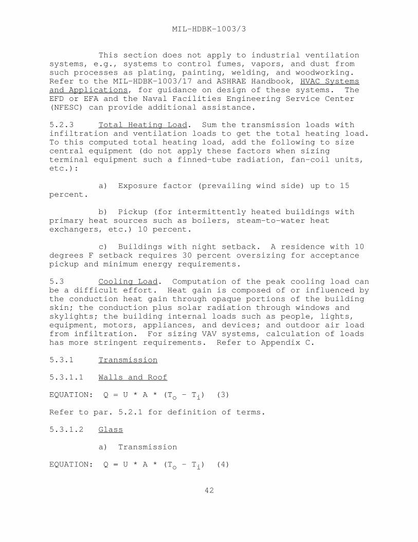
MIL-HDBK-1003/3
This section does not apply to industrial ventilationsystems, e.g., systems to control fumes, vapors, and dust fromsuch processes as plating, painting, welding, and woodworking. Refer to the MIL-HDBK-1003/17 and ASHRAE Handbook, HVAC Systemsand Applications, for guidance on design of these systems. TheEFD or EFA and the Naval Facilities Engineering Service Center(NFESC) can provide additional assistance.
5.2.3 Total Heating Load. Sum the transmission loads withinfiltration and ventilation loads to get the total heating load. To this computed total heating load, add the following to sizecentral equipment (do not apply these factors when sizingterminal equipment such a finned-tube radiation, fan-coil units,etc.):
a) Exposure factor (prevailing wind side) up to 15percent.
b) Pickup (for intermittently heated buildings withprimary heat sources such as boilers, steam-to-water heatexchangers, etc.) 10 percent.
c) Buildings with night setback. A residence with 10degrees F setback requires 30 percent oversizing for acceptancepickup and minimum energy requirements.
5.3 Cooling Load. Computation of the peak cooling load canbe a difficult effort. Heat gain is composed of or influenced bythe conduction heat gain through opaque portions of the buildingskin; the conduction plus solar radiation through windows andskylights; the building internal loads such as people, lights,equipment, motors, appliances, and devices; and outdoor air loadfrom infiltration. For sizing VAV systems, calculation of loadshas more stringent requirements. Refer to Appendix C.
5.3.1 Transmission
5.3.1.1 Walls and Roof
EQUATION: Q = U * A * (T - T ) (3)o i
Refer to par. 5.2.1 for definition of terms.
5.3.1.2 Glass
a) Transmission
EQUATION: Q = U * A * (T - T ) (4)o i
42

MIL-HDBK-1003/3
b) Solar Heat Gain
EQUATION: Q = A * (SC * SHGF)
where: SC = shading coefficient, and
SHGF = solar heat gain factor (look up the SHGF in ahandbook (e.g., ASHRAE Handbook, Fundamentals) for each exposureand type of glass).
5.3.2 Infiltration and Ventilation
a) Sensible
EQUATION: Q = 1.10 * CFM * (T - T ) (5)s o i
b) Latent
EQUATION: Q = 4840 * CFM * W (6)L
where: W = change in humidity ratio (lb water/lb air).
c) Ventilation Rates. Refer to ASHRAE Standard 62 orcontact the EFD or EFA for ventilation requirements for spacesnot listed below:
Auditoriums, theaters 15 cfm/personBarracks (sleeping rooms) 15 cfm/personBedroom 30 cfm/roomClassroom 15 cfm/personCommunication centers 20 cfm/personConference rooms 20 cfm/personCorridors 0.1 cfm/sq ftDining 20 cfm/personKitchens (commercial) (refer to Section 3)Lobbies 15 cfm/personLocker, dressing rooms 0.5 cfm/sq ftLounges, bars 30 cfm/personOffices (with moderate smoking) 20 cfm/personSmoking lounge 60 cfm/personToilet, bath (private) 35 cfm/roomToilet (public) 50 cfm/water closet or urinal
The total corrected outdoor air requirement for centralsystems supplying spaces with different ratios ofoutdoor-air-to-supply-air is determined from the following:
EQUATION: CFM = Y * CFM (7)ot st
43

MIL-HDBK-1003/3
where: CFM = corrected total outdoor air quantity,ot
CFM = total system airflow (i.e., sum of air suppliedstto all spaces), and
Y = corrected fraction of outdoor air, or
EQUATION: Y = X/(1 + X - Z) (8)
where: X = CFM /CFM ,oa st
Z = CFM /CFM ,oc sc
CFM = uncorrected sum of outdoor airflow rates foroaspaces on the system,
CFM = outdoor air required for critical space, andoc
CFM = supply air to the critical space. The criticalscspace is that space with the greatest required fraction ofoutdoor air in the supply to that space.
d) VAV system ventilation issues. Refer to Appendix C.
5.3.3 Internal Loads
5.3.3.1 People Loads. Adjusted (normal male/female/child).
Sensible Latent
Office (seated light work, typing) 255 Btu/hr 255 Btu/hrFactory (light bench work) 345 Btu/hr 435 Btu/hrFactory (light machine work) 345 Btu/hr 695 Btu/hrGymnasium athletics 635 Btu/hr 1165 Btu/hr
5.3.3.2 Lights and Equipment
a) Lights
EQUATION: Q = 3.41 * W * F * F (9)ul sa
where: W = total light wattage,
F = use factor, andul
F = special allowance factor for fluorescent fixturessaor for fixtures that release only part of their heat to theconditioned space.
44

MIL-HDBK-1003/3
b) Equipment
(1) Motors within conditioned space or withinairstream.
EQUATION: Q = 2545 * HP * F * F (10)lm um Em
where: HP = motor horsepower,
E = motor efficiency,m
F = motor load factor, andlm
F = motor use factor.um
(2) Appliances and equipment, such as businessmachines and computers. Refer to ASHRAE Handbook, Fundamentalsor contact the EFD or EFA for assistance in determining sensibleand latent heat gains from kitchen equipment.
EQUATION: Q = 3.41 * W * F (11)s ue
where: Q = sensible load,s
W = appliance wattage, and
F = equipment use factor.ue
c) Heat Gain From Miscellaneous Sources
(1) HVAC Fan Motors (Outside the Airstream). Thirty-five percent of the input to an HVAC fan motor isconverted to heat in the airstream because of fan inefficiency. Refer to par. 5.3.3.2 b)(1).
(2) HVAC Fan Motors (Within the Airstream). Themotor load is converted to heat. Refer to par. 5.3.3.2 b)(1).
(3) Duct Leakage. Loss of supply air due to ductleakage shall be compensated by system capacity as follows:
(a) Well designed and constructed system: increase fan capacity by 3 percent.
(b) Poorly designed and constructed system: increase fan capacity by 10 percent.
45

MIL-HDBK-1003/3
Section 6: AIR DISTRIBUTION
6.1 Duct Design for HVAC Systems
6.1.1 Sizing General. See Figure 2 for duct sizing. ASHRAEHandbook, Fundamentals recognizes three methods of sizingductwork: the equal friction method, the static regain method,and the T-method. For design of small simple systems, the equalfriction method will suffice. Use the static regain method forVAV design (refer to Appendix C).
6.1.2 Equal Friction Method Sizing. Select a constantpressure loss in inches of water per 100 foot length of duct fromthe preferred part of Figure 2. The preferred part of Figure 2is between 0.08 and 0.6 inches of water per 100 feet frictionloss for air quantities up to 18,000 cfm, and between 1800 fpmand 4000 fpm for air quantities greater than 18,000 cfm. Use lowvelocities and a low friction drop for small projects, or whereductwork is cheap and energy is expensive. For systems of 18,000cubic feet per minute and over, use a friction loss of 0.08 andvelocities of 1800 to 3000 feet per minute. After sizing theentire system at the selected unit pressure drop, go back andadjust velocities and pressure drops in the shorter branches toequalize the pressure drops at each duct branch junction. Thedesigner must observe the recommended permissible room soundpressure levels for various applications discussed in NFGS-15895,Ductwork and Ductwork Accessories.
6.1.3 Ductwork General
6.1.3.1 Round Ducts. Use round ducts wherever possible. Undernormal applications, the minimum duct size shall be 4 inches indiameter. Use smooth curved elbows as much as possible. Ifthese are not available, use three-piece elbows for velocitiesbelow 1600 feet per minute and five-piece elbows for velocitiesabove 1600 feet per minute. The throat radius shall not be lessthan 0.75 times the duct diameter.
6.1.3.2 Rectangular Ducts. Use a minimum duct size of 6 inchesby 6 inches. Where possible, keep one dimension constant intransitions and do not make transitions in elbows. Maketransitions in sides and bottom of the duct keeping top level tomaintain maximum clearance above ceiling. The transition slopeshall be 30 degrees on the downstream. Where ductwork isconnected to equipment fittings such as coils, furnaces, orfilters, the transition shall be as smooth as possible. Drawingsshall indicate ductwork pitch, low spots, and means of disposingof the condensate. Elbows shall be smooth, with an inside radiusof 1.0 times the width of the duct. Where space constraints
46

MIL-HDBK-1003/3
Reprinted by permission of American Society of Heating, Refrigerating, &Air-Conditioning Engineers, Inc., Atlanta, GA from ASHRAE Handbook,Fundamentals.
47

MIL-HDBK-1003/3
dictate use of mitered elbows, such elbows shall have singlethickness turning vanes. Using double thickness turning vanesinstead of single thickness vanes increases the pressure loss ofelbows by as much as 300 percent. Use the circular equivalentstable in ASHRAE Handbook, Fundamentals instead of matching areaswhen you change aspect ratios. The aspect ratio is the ratio oflarger to smaller rectangular duct dimension. Try to use anaspect ratio of 3 to 1 with a maximum aspect ratio of 6 to 1 orless.
6.1.3.3 Access Doors. Show access doors or panels in ductworkfor apparatus and devices for maintenance, inspection, andservicing.
6.1.3.4 Flexible Ducts. To save construction expense, flexibleduct may be used to connect ceiling outlets. Limit the length offlexible ducts to straight runs of 5 feet. Seek self-balancingby having equal lengths of flexible ducts instead of long andshort lengths on the same branch. Do not use flexible ducts forelbows, including connection to diffusers; provide elbows atceiling diffusers. Do not use flexible ducts in industrialventilation systems.
6.1.3.5 Rooftop Ductwork. Rooftop ducts exposed to the weathercan leak rain water. Exterior insulation tends to have a shortlife. One way to avoid such problems is to put insulation insidethe duct, and then use galvanized steel ductwork with solderedjoints and seams. Exterior insulation shall have weatherizedcoating and wrapping throughout, where it must be used; such ason kitchen exhaust hoods containing grease.
6.1.3.6 Glass Fiber Ductwork. Investigate the bidding climatein your local area before deciding that ductwork made from glassfiber panels will always be less expensive than galvanized steelductwork. Fiberglass ductwork should be coated inside to avoidbacteria growth. In some parts of the country the sheet metalsubcontractor can make or buy metal ducts made on an automaticmachine at competitive prices.
6.1.3.7 Balancing Dampers for HVAC. Provide balancing damperson duct branches and show dampers on drawings. See Figure 3 fordamper installation. Use extractors or volume dampers instead ofsplitter dampers at branch connections. Do not use splitterdampers since they make ductwork more difficult to balance than ajob with volume dampers. Provide access in the ceiling andclamping quadrants for dampers or use a type with a remotecontrol that extends through the ceiling. Outdoor air dampersshould be located away from the intake louver and after the ducttransition to minimize exposure to weather and oversizing of
48

MIL-HDBK-1003/3
49

MIL-HDBK-1003/3
dampers. Avoid using balancing dampers for industrialventilation (IV) systems. Design IV ductwork so that the systemwill function properly without balancing dampers. Do not usebalancing dampers when designing a VAV system. A VAV system withductwork designed using the static regain method and properlysized VAV terminal units is inherently self-balancing. Refer toAppendix C for additional information.
6.1.3.8 Fire Dampers and Smoke Dampers
a) Fire Dampers. The term "fire damper" usually meansa curtain type damper which is released by a fusible link andcloses by gravity or a mechanical spring. Fire dampers aremounted in walls of fire rated construction to ensure integrityof the space. Fire dampers should be installed where the passageof flame through a fire rated assembly is prohibited. Refer topar. 4.1.3 for duct pressure classification requirements.
b) Combination Fire and Smoke Dampers. The term"combination fire and smoke damper" usually means a fire damperwhich is automatically controlled by an external source (such asa fire alarm control panel or energy management system) to stoppassage of both fire and smoke. Combination fire and smokedampers should be installed where passage of fire or smoke isprohibited. Activation of combination fire and smoke dampers canbe by several methods including pneumatic damper operators,electric damper operators, and electro-thermal links. Electro-thermal links include explosive squibs which are notrestorable and McCabe type links which are restorable. Pneumatically operated dampers are the preferred method of damperactivation, and should be configured in the fail-safe mode suchthat loss of pneumatic pressure will result in dampers closure.
In electronic data processing rooms, combination fireand smoke dampers should be installed in walls with a fireresistance rating of 1 hour or greater. In other type spaces,either fire dampers or combination fire and smoke dampers shouldbe installed in walls with a fire resistance rating of 2 hours orgreater. Where a smoke damper is required to stop passage ofsmoke through a barrier (e.g., hospitals), the installation of acombination fire and smoke damper is required.
c) Mounting Details. Fire dampers and combinationfire and smoke dampers must remain in the wall during a fire. Though ductwork may collapse, the damper should remain in thefire rated assembly, therefore, indicate on drawings the detailsfor attaching dampers to the wall. Use UL listed firestoppingmaterials between the damper collar and the wall, floor, orceiling assembly where penetrated.
50

6.1.3.9 Fan System Effect Factors. Fans are tested and ratedbased upon a certain standard ductwork arrangement. If installedductwork creates adverse flow conditions at the fan inlet or fanoutlet, loss of fan performance is defined as a system effectfactor. The system effect factor can be caused by obstructionsor configurations near the fan inlet and outlet. For example,failure to recognize the affect on performance of swirl at thefan inlet will have an adverse effect on system performance. SeeFigure 4 for methods to minimize fan system effect factors. Refer to Air Movement and Control Association (AMCA) 201, Fansand Systems for additional information on fans and systemeffects.
6.1.4 Ductwork Details
6.1.4.1 Branches. See Figure 5 and Figure 6.
6.1.4.2 Elbows. See Figure 7.
6.1.4.3 Offsets and Transitions. See Figure 8.
6.1.5 Testing and Balancing. Ensure duct design includesadequate provision for testing and balancing, including straightsections of duct with ports for velocity measurement. Airstraighteners may be required if sufficient lengths of straightduct are not available.
6.2 Fans for HVAC Systems
6.2.1 Fan Selection
6.2.1.1 Major Types of HVAC Fans. See Table 7.
6.2.1.2 Size. In most applications, the fan capacity requiredis a function of heating and cooling loads, except where there isa minimum prescribed air movement, such as an operating suite ina hospital.
For the total room sensible heat load, calculate theminimum supply air quantity to satisfy the sensible heat load asfollows:
EQUATION: CFM = Q /(T - T ) * 1.10 (12)s r s
where: CFM = supply air quantity (cubic feet per minute),
T = room design temperature (degrees F dry bulb), andr
T = supply air temperature (degrees F dry bulb)s
51

MIL-HDBK-1003/3
The quantity of supply air shall also be calculatedusing the cooling load calculation from equation (5) ofpar. 5.3.2.
Add the extra dehumidification load of ventilation air(due to lower room humidity) to the grand total heat load.
6.2.1.3 Sound Rating. In large central systems, one shouldstart with the noise limit that may be tolerated in the selectedroom criteria and than work backwards through the system to thefan. ASHRAE Handbook, HVAC Systems and Applications containsnoise guidance, and Army TM 5-805-4 gives noise criteria forvarious room types. See Table 2-1 of Army TM 5-805-4 for indoornoise criteria.
By isolating the fan on vibration pads, selecting a fanin the efficient range, and utilizing the attenuation ofductwork; the fan and air noise can be controlled. Refer to thefan manufacturer's data sheet for fan noise values.
6.2.1.4 Static Pressure Requirement. To select a fan from thefan manufacturer's fan curves, it becomes necessary to establishthe system static pressure requirement as well as the volume ofair delivery. With some types of packaged equipment, this ratingis called "external static pressure" and static pressure dropsrequired by coils, filters, etc., inside the equipment havealready been allowed. With central system fans, however, thestatic pressure requirement in the entire system must beestablished to select the total fan static pressure. Verify howindividual manufacturers rate their equipment and check theircurves and tables for system effects. Select fans so that theywill remain stable and not overload at any operating condition.
a) Pressure Drop of Air Handling Systems. Pressuredrop calculations of air handling systems shall include:
(1) Outdoor air intake louvers,
(2) Dampers,
(3) Air filters (average between clean and dirty),
(4) Heating coils,
(5) Cooling coils (wet, dry, or sprayedcondition),
(6) Moisture eliminators,
52

MIL-HDBK-1003/3
Reprinted by permission of American Society of Heating, Refrigerating, &Air-Conditioning Engineers, Inc., Atlanta, GA from ASHRAE Handbook Fundamentals.
53

MIL-HDBK-1003/3
54

MIL-HDBK-1003/3
55

MIL-HDBK-1003/3
56

MIL-HDBK-1003/3
57

Type HVAC Application
Centrifugal with backward Large HVAC systems where faninclined airfoil blades energy efficiency becomes
significant
Backward inclined centrifugal General HVAC
Forward inclined centrifugal Low pressure HVAC, mainly infurnaces and package equipment
Vane axial General HVAC where compact sizeand straight flow is wanted
Propeller Equipment room ventilation andgeneral ventilation for comfortcooling
MIL-HDBK-1003/3
Table 7Major Types of HVAC Fans
(7) Fan entrance (including vortex dampers),
(8) Fan discharge (based on dischargeconfiguration), and
(9) Velocity pressure loss (if fan outlet velocityis lower than duct velocity).
b) Pressure Drop of Duct Systems. Pressure dropcalculations of duct systems shall include:
(1) Straight unlined or lined ductwork,
(2) Static pressure regain or loss due totransitions,
(3) Fittings,
(4) Branch takeoffs,
58

MIL-HDBK-1003/3
(5) Obstructions,
(6) Fire and smoke control dampers,
(7) Regulating dampers,
(8) Takeoff neck for air terminal devices,
(9) Air terminal devices, and
(10) Sound traps.
6.2.1.5 VAV Fan Selection. When selecting a fan for a VAVsystem, check fan operating characteristics throughout the rangefrom minimum to maximum flow conditions operating conditions. Fans should not be selected that will become unstable oroverloaded for any operating condition. Fan manufacturer shallbe AMCA certified. Refer to Appendix C for additionalinformation.
6.3 Economizer Cycle. The economizer cycle providescooling without refrigeration using outdoor air when outdoor airdry bulb temperature is below a predetermined temperature wherethe total heat of outdoor air is likely to be lower than that ofthe return air. Economics of the economizer cycle isparticularly attractive for facilities that have interior zonesrequiring year around cooling or for facilities with internalheat gains higher than heat losses through the envelope of thebuilding. The economizer cycle should only be used with approvalof the EFD or EFA. Refer to pars. 8.2, 8.3, 8.4, and 8.5 for therecommended control sequence.
6.4 Terminal Equipment. Conditioned air is delivered tothe room through terminal equipment such as grills, registers,ceiling diffusers, etc. To achieve appropriate air diffusionwithin the room, the terminal equipment should provide:
a) Mixing of conditioned air with room air, and
b) Counteraction of natural convection and radiationeffects within the room.
The scheme used to deliver conditioned air to the roomdepends upon room size, geometry, exposures, and use patterns. Outlet types include grills and diffusers mounted in or near theceiling and floor or low sidewall outlets. Outlet types shouldbe selected to adequately throw supply air across the room; toprovide good mixing to prevent drafts; to counter the buoyancyeffect of temperature differences; and to avoid obstructions such
59

MIL-HDBK-1003/3
as beams and light fixtures that could divert supply air directlyon the occupants. Linear slot diffusers are important in VAVsystems (refer to Appendix C).
6.5 Louvers
a) Louvers are used to admit supply air, dischargeexhaust air, or admit return air to the ductwork system. Oftenthese are detailed on architectural drawings and installed underarchitectural sheet metal because the architectural designerwants to control the esthetics of the building exterior. Consider the following in placement of intake louvers so theyare:
(1) Not exposed to blowing dust, driving rain,high winds, auto exhaust fumes (loading docks), embanked snow, orfalling leaves.
(2) Away from known odors, airborne contaminants,cooling towers, and industrial exhaust stacks (25 foot minimum).
(3) Away from building entrances where radiatednoise from the fan equipment could be annoying.
(4) Away from building exhaust air, buildingplumbing vents, and odors from kitchen hood exhausts, andlaboratory exhausts.
b) In the design of louver blades, a proper compromisemust be made between maximum net free area and trapping ofwindblown rain. See Figure 9 for a typical rain resistantlouver.
c) Keep air velocities low through louver intakes toavoid noise and excessive pressure drops. Compute pressure dropbased on the percent of free flow area for the louver and thepressure drop through insect and bird screens.
d) For industrial ventilation systems with fume hoods,makeup air should be introduced through a perforated ceiling,ceiling panels, or perforated ducts to distribute the airuniformly throughout the room.
6.6 Filters for HVAC Systems. Use high efficiency filtersonly if the mission requires clean air since they cost more toinstall and maintain, take more space, and use more energy. Highefficiency filters should be preceded by pre-filters to extend
60

MIL-HDBK-1003/3
their life. Use the least efficient filter that will satisfymission requirements. Some available filter types and theirapplications include the following:
Filter Type Applications
Flat throwaway Window air conditioners, warm air furnaces, packaged unitary equipment, central air handlers (when high efficiency is not required)
Flat permanent Same as for flat throwaway but require cleaning
Roughing or pre-filters For removing larger particles ahead of high efficiency filters to extend filter life
High efficiency air Operating rooms, clean rooms,(HEPA) filters protective shelters
Renewable media Large outdoor air systems with high(auto-cleaning) dust loads to reduce frequency of filter changes; roughing or pre-filters
Electrostatic For high efficiency with low pressure drop (precede with pre-filter to reduce cleaning requirements)
Consider also the ambient dust level of the air.
A classic illustration of poor design is a building ata desert station with low air intakes located adjacent to anunlandscaped helipad. Each time a helicopter lands or takes off,huge quantities of dust are drawn into the HVAC filters. Whenselecting a filter bank for an installation, consider the type offan and the fan curve. A packaged cabinet fan unit with forwardcurved blades may not have sufficient static pressure to maintainrequired airflow with dirty HEPA filters.
6.7 Access for Inspection and Maintenance. Airdistribution systems of an HVAC plant require access forinspection and maintenance. During design consider how filters,motors, and fan belts will be replaced and cleaned. Designsystems to avoid the following:
a) Using a step ladder in the middle of an office toremove a ceiling tile and rig portable lighting to maintainequipment.
61

MIL-HDBK-1003/3
b) Need to crawl on hands and knees under ductwork carrying filters, tools, etc.
c) Need to climb over a rooftop screening fence to get to roofmounted HVAC equipment.
d) Use of a vertical ladder to open a roof hatch while carryingfilters, tools, etc.
e) Need to rig a portable walkway in a ceiling assembly to approacha remote fan coil unit or other equipment.
6.8 VAV System Design. Unless VAV systems are well designed andexpertly installed, problems can develop. Refer to Appendix C for designconsiderations.
6.9 Ductwork Pressure-Velocity Classification. It is essential thatductwork pressure-velocity classification be specified clearly in drawings foreach duct system. Note the following:
a) Ductwork pressure-velocity classification may be different fordifferent ductwork systems.
62

MIL-HDBK-1003/3
b) Ductwork pressure-velocity classification may bedifferent at different parts of any single duct system.
c) SMACNA HVAC duct construction standards should beused for pressure-velocity classification.
d) SMACNA classifications are based on maximum staticpressure as follows:
STATIC PRESSURE
Pressure Class Operating Pressure
1/2" WG Up to 1/2" WG1" WG Over 1/2" WG to 1" WG2" WG Over 1" WG to 2" WG3" WG Over 2" WG to 3" WG4" WG Over 3" WG to 4" WG6" WG Over 4" WG to 6" WG10" WG Over 6" WG to 10" WG
See Figure 10 for an example of how to delineate ductpressure class designation.
63

MIL-HDBK-1003/3
64

MIL-HDBK-1003/3
Section 7: PIPING SYSTEMS
7.1 General
7.1.1 Piping Design Factors. Consider the choice betweensteel and copper piping based on estimated initial cost and lifecycle cost of each installation. For a safe pressure of pipingand fittings corresponding to working pressure and temperature,refer to ASME B31.1, Power Piping. See Table 8.
Copper piping cannot be corroded by fluorinatedhydrocarbon refrigerants, even when this liquid is mixed withmoisture. Copper is entirely free of scaling effects. However,steel pipe and fittings are less expensive than copper piping fornon-refrigerant systems with larger pipe sizes.
7.1.2 Pipe Friction Loss. For pipe friction loss, seeFigures 11 through 13 for water flow and Figures 18 through 21for steam flow.
7.1.3 System Pressure Loss. Piping system pressure losscalculations shall include the following considerations:
a) Pipe friction based on 10-year-old pipe;
b) Pressure loss of valves, fittings, and otherassociated equipment;
c) Equipment pressure loss;
d) Static lift in open systems.
7.1.4 Piping Layouts. Piping layouts shall provide for flowcontrol, subsystem isolation, pipe expansion, elimination ofwater hammer, air removal, drainage, and cathodic protection. Isolation valves are required in piping systems. To controlcorrosion, provide cathodic protection as required due topresence of dissimilar metals, stray currents, or soilcomposition (if using direct burial pipe), as described inMIL-HDBK-1004/10, Electrical Engineering Cathodic Protection.
7.1.5 Expansion. Preferred methods of accommodating thermalexpansion are by pipe geometry, e.g., offsets and changes indirection, and pipe loops. Offsets that would cause torsionshould be avoided with screwed fittings to prevent the potentialfor leaking joints. Use expansion joints only when space doesnot permit proper geometry or installation of pipe loops. Forexpansion as a function of temperature for steel and copper pipe,and general expansion criteria, see Table 12 of MIL-HDBK-1003/8A,
65

MIL-HDBK-1003/3
Exterior Distribution of Utility Steam, High Temperature Water(HTW), Chilled Water, Natural Gas and Compressed Air. Forinformation on piping flexibility design, refer to Crocker,Piping Handbook, Kellogg, Design of Piping Systems, or similarreferences.
7.1.6 Expansion Loop. On straight pipes, always useexpansion loops if space conditions permit.
7.1.7 Packing-Type Expansion and Ball Joints. Providepacking-type expansion and ball joints only if they can belocated in accessible areas. These expansion joints shall not beused for refrigerant piping. Packing-type expansion joints canbe used, however, for chilled water, hot water, or steam linesunder limited conditions. Packing-type joints fail slowly,giving a warning by leakage.
7.1.8 Bellows Expansion Joints. Use bellows-type expansionjoints where piping is not easily accessible. Bellows-typejoints can fail suddenly without warning and should not be usedwhere personnel would be endangered by a rupture.
7.1.9 Supports and Anchors. Expansion joints should beprovided with guides to prevent undue bending movement. Pipingbetween expansion joints should have supports designed to carrythe weight of the pipe and fluid together with axial frictionloads and the thrust of the expansion joint. Risers and mainsshould be anchored to prevent excessive strain on branches. Consider whether the building structure will withstand the thrustof piping on the anchor. In light steel or wood framestructures, consider allowing the piping system to float withexpansion loops but without anchors.
a) Supports. Provide shields between the insulationand the supports of insulated piping. Provide roller-type guidedsupports where horizontal pipe is subject to thermal expansion. Provide vertical pipes and main risers with base elbows designedto take the weight of the pipe from the elbow up to the firstanchor.
b) Hangers. Provide hangers with vibration isolators,as required. Hangers shall be massive enough to limit thevibration amplitude. Pipe supports shall be wide enough to avoidany swivel action. Use spring hangers when required toaccommodate expansion in vertical piping. Provide seismicsupport in the lateral direction where this is appropriate.
66

SERVICE PIPE FITTINGS
Suction line Hard copper tubing Wrought copper, wrought(Refrigerant) Type L(1) Brass, or tinned cast
Steel pipe, standard brass, 150 lb welded or wall lap welded or threaded malleable iron
seamless for sizeslarger than 2 in. IPS
Liquid line Hard copper tubing Wrought copper, wrought(Refrigerant) Type L(1) or tinned cast brass,
Steel pipe: extra 300 lb welded orstrong wall for sizes threaded malleable iron1-1/2 in. IPS andsmaller. Standard wallfor sizes larger than1-1/2 in. IPS, lapwelded or seamless forsizes larger than 2 in.IPS
Hot Gas Line Hard copper tubing Wrought copper, wrought(Refrigerant) Type L(1) brass or tinned cast
Steel pipe, standard brass, 300 lb welded orwall lap welded or threaded malleable ironseamless for sizeslarger than 2 in. IPS
Chilled Water Black or galvanized Welded, galvanized,steel pipe(2) cast, malleable, orHard copper tubing(2) black iron (3)
Cast brass, wrought copper, or wrought brass
Condenser or Galvanized steel Welded, galvanized cast,Makeup Water pipe(2) malleable iron(3)
Cast brass, wrought copper, or wrought brass
MIL-HDBK-1003/3
Table 8Piping Materials
67

SERVICE PIPE FITTINGS
Drain or Galvanized steel Galvanized, drainage,Condensate pipe(2) cast, or malleableLines iron(3)
Hard copper Cast brass, wrought tubing (2) copper, or wrought brass
Steam or Black steel pipe(2),(4) Welded or cast iron(3)Condensate Hard copper tubing(2), Cast brass, wrought
(4) copper, or wrought brass
Hot Water Cast steel pipe Welded or cast iron(3) Hard copper tubing(2) Cast brass, wrought
copper, or wrought brass
(1) Soft copper Type L can be used for sizes 7/8 in. OD and smaller, except for sizes 1/4 in. and 3/8 in. OD (Type K must be used for 1/4 in. and 3/8 in. OD sizes).
(2) Normally standard wall steel pipe or Type L hard copper tubing is satisfactory for air conditioning applications, however, the piping material selected shall be checked for design temperature-pressure ratings.
(3) Normally 125 lb cast iron and 150 lb malleable iron fittings are satisfactory for air conditioning applications, however, the fitting material selected shall be checked for temperature-pressure ratings.
(4) For steam condensate return lines use Schedule 80 black steel or Schedule 80 wrought iron pipe. Where hard copper tubing is used, check for compatibility with condensate.
MIL-HDBK-1003/3
Table 8 (Continued)Piping Materials
7.1.10 Flexible Hose. Flexible connections can be installedbetween moving components and piping. Consider the dual use offlexible hoses as a union point. Pipe shall be anchored at theend, away from moving components.
68

Type of Service Recommended Velocity (fps)
General Service 4 to 7
City Water 3 to 7
Boiler Feed 6 to 15
Pump Suction and Drain Lines 4 to 7
MIL-HDBK-1003/3
7.2 Water Systems
7.2.1 General. The following applies to both hot and chilledwater systems.
7.2.1.1 Exterior Water Piping Design. For exterior pipingdesign criteria, refer to MIL-HDBK-1003/8A.
7.2.1.2 Water Velocity. Noise, erosion, and pumping costs canbe excessive if the water velocity selected is too high. Installation costs become excessive if the selected watervelocity is too low. Table 9 gives recommendations:
Table 9Water Velocities
7.2.1.3 Water Treatment. Selection of a water treatment systemis based on analysis of makeup water and its anticipatedcontribution to internal corrosion and scale formation indistribution piping and heat transfer equipment, both of whichwill affect system efficiency and capacity. Obtain services of awater treatment specialist to perform a water analysis, if notavailable at the site, and to make specific recommendations ontype and quantity of chemicals used. Coordinate the decision ontype of chemicals specified with the local environmental programmanager to ensure chemicals can be properly handled and disposedof and that pollution control regulations are properly addressed.
69

MIL-HDBK-1003/3
7.2.1.4 Pipe Sizing. Refer to ASHRAE Handbook, Fundamentals orFigures 11, 12, and 13 for pipe sizing. Guidance parameters forsizing are as follows:
a) Charts are based on use of 60 degree F water. Theyare conservative (e.g., overestimate the pressure drop) for 200degree F water; and are not conservative for chilled water.
b) A mean pressure drop selection might be 2.5feet/100 feet. Pressure drops of over 4 feet/100 feet can beused for pipes over 2 inches in diameter.
c) Keep the minimum velocity above 2 feet per second,and increase this velocity in down-feed return mains. Lowervelocities cause separation of entrained air in the mains.
7.2.1.5 Valve and Fitting Pressure Drops. Add the equivalentvalve and fitting piping length to the system when performinghydronic computations.
7.2.1.6 Return Arrangements. The two-pipe reverse returnsystem has two mains, one supplying and one returning water fromheating units. The return piping is longer than that of a directreturn system and is arranged so that the equivalent lengths ofsupply and return piping to any heating unit are about equal. Use reverse return piping arrangements on closed systems, if allunits or parallel circuits have nearly equal resistance. Do notuse reverse return piping on open or once-through systems. Provide a reverse return in an up-feed system, and provide areverse supply in a down-feed system. Isolation and drain valvesare required in piping systems.
7.2.1.7 Air Vents. Water flow, especially through heattransfer equipment, shall be directed to permit natural airventing. Install air vents at system high points.
7.2.2 Hot Water Heating Systems
7.2.2.1 Hot Water Piping. Refer to pars. 7.1 and 7.2.1 forpiping and pipe sizing.
7.2.2.2 Hot Water Coils. Hot water coils are used in ducts ofan HVAC system to heat the air. Their extended surface isprovided by fins that are bonded to the coil tube. The mostcommon design is attaching aluminum fins to copper tubing with amechanical bond. Headers are usually provided between the tubes,with supply water entering the coil low and return high so thecoil will be self-venting of any entrained air that enters thecoil.
70

MIL-HDBK-1003/3
Reprinted by permission of ASHRAE, from ASHRAE Handbook, Fundamentals.
71

MIL-HDBK-1003/3
Reprinted by permission of ASHRAE, from ASHRAE Handbook, Fundamentals.
a) Hot Water Piping to Coil. Water coils will not perform if thereis air in the piping. Ensure that the piping from the main, to the coil, andto the return main is appropriately sloped up and vented to eliminateentrained air that can air lock the flow.
b) Hot Water Coil Selection. Consult the manufacturer's catalogdata to decide the best selection, number of rows, parallel or counter flow,turbulators or serpentines, and other selection information. Using theappropriate type, make the coil selection:
(1) Capacity required
(2) Water temperature in and out
(3) Air temperature in and out
(4) Airflow
(5) Water flow
(6) Air pressure drop
72

MIL-HDBK-1003/3
(7) Water pressure drop
(8) Coil face velocity
(9) Any special requirements
After the coil selection has been made and documentedin the design analysis, be sure to provide the above data in thecoil schedule on drawings. This will ensure a good biddingclimate, with equipment manufacturers knowing what to bid, andwhat to submit in the shop drawings phase.
7.2.2.3 Expansion Tanks and Air Separator
a) Expansion Tanks General. When water in a hot waterheating system is heated, water expands and occupies more volume. System pressure control is needed to:
(1) Limit pressure in all parts of the system tothe allowable working pressure.
(2) Maintain minimum pressure in the system toprevent pump cavitation and to prevent boiling of system water.
(3) Minimize addition of makeup water.
b) Expansion Tank With Air Separator. An expansiontank with an air separator performs these system pressure controlfunctions. Since this section does not address mediumtemperature hot water system (250 to 350 degrees F) or hightemperature hot water system (above 350 degrees F); discussionwill be limited to the following types of tanks:
(1) Closed expansion tanks with an air cushion. See Figure 14.
(2) Diaphragm (or bladder) type closed expansiontanks. See Figure 15.
Open expansion tanks located at the system high pointwill also work on low temperature hot water systems, but are notgenerally used on Navy building projects.
c) Expansion Tanks. Some specifics regardingexpansion tanks are as follows:
(1) Expansion tanks are required on chilled waterand hot water systems.
73

MIL-HDBK-1003/3
(2) Locate the tank on the suction side of thesystem pump so that system pressure is always positive withrespect to atmospheric pressure.
(3) Do not install a shutoff valve between theheat source and the expansion tank.
(4) Refer to ASHRAE Handbook, HVAC Systems andApplication or manufacturer's literature for tank sizing.
(5) See Figure 14 for closed expansion tankplacement.
(6) See Figure 15 for diaphragm expansion tankplacement.
(7) Do not use a gage glass on the expansion tank. A gage glass on a steam boiler is permitted since the wet steamvapor keeps the upper glass packing tight. With an expansiontank, the air will dry out the upper gage glass packing and causeair leaks.
7.2.2.4 Domestic Hot Water Generator. An interface occursbetween the heating system and the plumbing system when boilersteam or boiler hot water is used to heat water for plumbingfixtures. Some points to consider in heating domestic hot waterare as follows:
a) Domestic water can be heated by the boiler (steamor hot water) or a separate hot water generator, if the heatingsource is available during the summer. If heated by the spaceheating boiler, evaluate boiler efficiency for summer operation.
b) If the space heating boiler provides hot water,evaluate if it should be an instantaneous heater, a semi-instantaneous heater, or a storage type hot water generator. Theselection will affect the boiler capacity specified. Refer toNAVFAC DM-3.01, Plumbing Systems for domestic hot water systemdesign.
With these decisions made, select the hot water systemand equipment. See Figure 16 and Figure 17.
7.2.2.5 Heat Exchangers. Heat exchangers are used for steam toheat water. One medium flows through the shell, and the othermedium flows through the tubes in the tube bundle. Include thefollowing in the equipment schedule:
a) Water flow
74

MIL-HDBK-1003/3
75

MIL-HDBK-1003/3
76

MIL-HDBK-1003/3
77
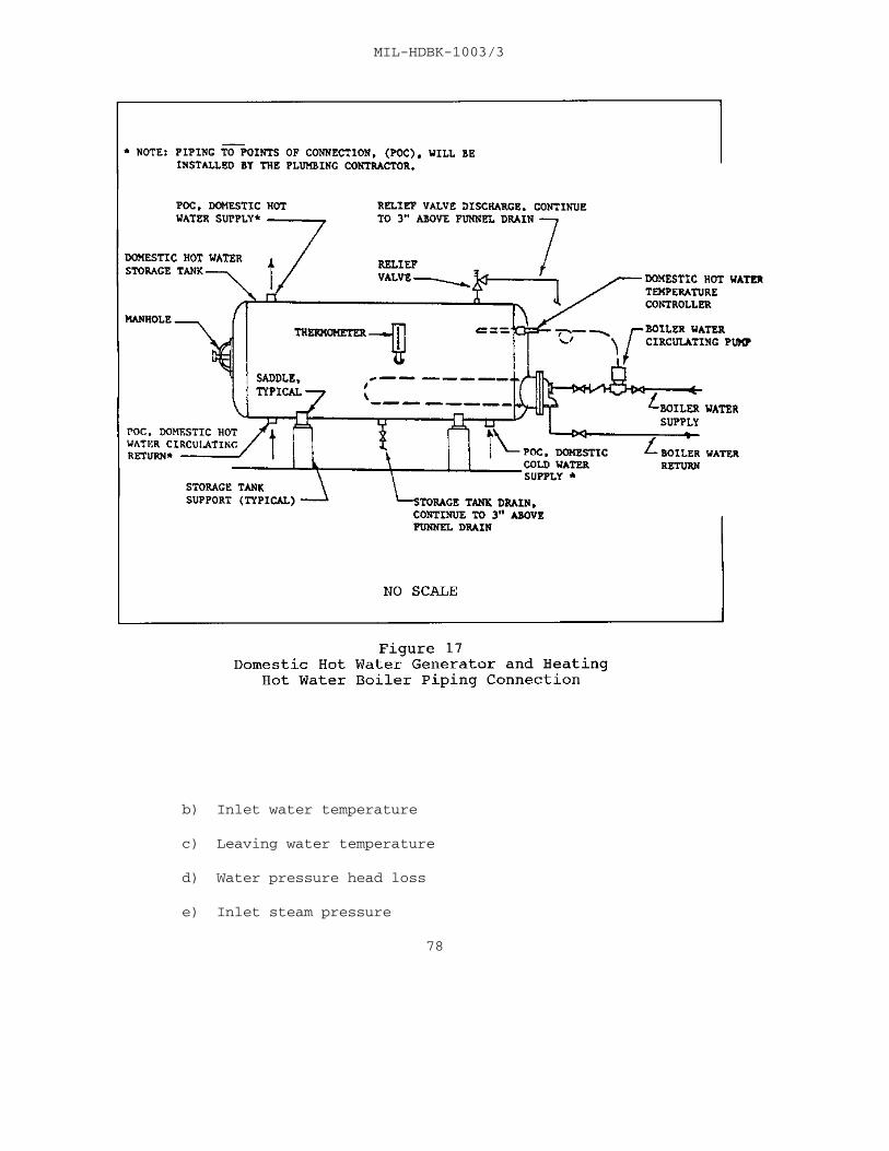
MIL-HDBK-1003/3
b) Inlet water temperature
c) Leaving water temperature
d) Water pressure head loss
e) Inlet steam pressure
78

MIL-HDBK-1003/3
f) Steam flow
g) Trap size and rating
h) Shell pressure rating
i) Tube bundle pressure rating
j) Control Valve Cv
k) Temperature control scheme (e.g., resetting thewater temperature from the outdoor temperature)
Converters shall be ASME rated and stamped. Detail thesupports for the converter and the expansion tank. See Figures16 and 17.
7.2.2.6 Pumps. In hydronic systems that are larger thanresidential size, a two pipe system with a circulating pump isrequired to make the heating system responsive to load changes. Note the following:
a) Provide a pressure gage on each side of the pump,or a differential gage connected between pump suction anddischarge to facilitate system balancing.
b) Provide flow gages in the branches of multizonesystems to facilitate balancing.
c) Provide gate valves and unions or flanges on inletand outlet piping to equipment to expedite future removal andrepairs.
d) Provide strainers on the suction side of the pump.
e) Do not overestimate the pumping head on the pump. A conservative overestimation of the head can result in the pumpdelivering more than the required gpm and thereby requiring morehorsepower than estimated. There are three solutions to this:
(1) Specify a pump that is non-overloading,
(2) Show a throttling valve in the pump dischargeto increase the head if needed, and
(3) Remove the impeller and machine it to reducecapacity.
79

MIL-HDBK-1003/3
f) Low temperature hot water heating systems are oftendesigned for a 20 degree F temperature drop. This makes it easyto size the pump--divide the Btu's by 10,000 to obtain the pumpgpm.
g) Pumping systems that are open, such as coolingtowers, or systems with hot liquids, such as a deaerator feedpump, require special attention to ensure proper NSPH. Keep thepump low enough and close enough to maintain proper NPSH.
h) Calculate pipe and fitting friction drop, the headloss through the coils, control valves, heat exchanger, etc. Tothis add any static head, if the system is not a closed system. Also add nozzle loss for spray equipment, such as evaporativecondensers, cooling towers with nozzles, or air washers.
I) Arrange pumps in parallel, i.e., one pump for eachboiler, chiller, cooling tower, etc.
7.2.3 Chilled Water
7.2.3.1 Pipe Size. Refer to pars. 7.1 and 7.2.1. For dualtemperature systems, note that the required temperaturedifference and the required flow may be different for heating andfor cooling operation.
7.2.3.2 Coils. Refer to par. 7.2.2.2. Note the following:
a) Multiple rows may be needed for humidity control. With cooling coils it is important to specify the entering andleaving wet bulb temperature and add the latent load ofdehumidification.
b) Dehumidifying coils will need drip pans and drains.
7.2.3.3 Expansion Tanks. Refer to par. 7.2.2.3. Expansiontanks are required to provide for change in water volume due tochanges in temperature.
7.2.3.4 Pumps. Refer to par. 7.2.2.6. It is common with largechilled water systems to check the economics of pumping systems. Is it lower cost to pump more or less flow on the chilled waterand cooling water circuits? Should colder chilled water, smalleror larger pipes, a bigger chiller, warmer condenser water, orsmaller cooling towers be used? Evaluate the life cycleeconomics on several alternatives to select the most costeffective solution.
80

MIL-HDBK-1003/3
7.3 Steam
7.3.1 General. Low pressure steam in HVAC systems is definedas 15 psi or less. High pressure steam in HVAC systems isdefined as being 16 psi to 150 psi. There is a trend away fromusing direct steam in HVAC systems. If one gets heat fromdistrict steam or a steam boiler, the designer will often convertthe steam to hot water through a heat exchanger to supply theHVAC system. The reasons for using hot water HVAC systemsinclude the following:
a) Eliminates maintenance of many steam traps.
b) More flexible when planning temperature controls.
7.3.2 Low Pressure Steam Systems
7.3.2.1 Pipe Sizing. Pipe sizing for low pressure steam andreturn mains is found in ASHRAE Handbook, Fundamentals. SeeTables 10 through 13. Note the following:
a) Slope steam mains in the direction of the flow(½ inch in 10 feet is recommended).
b) Slope return mains similarly.
c) Avoid lifts on low pressure returns, or make themsmall.
d) Pumped returns are preferred to gravity returns.
e) Provide a step-up and drip at the base of steamrisers.
f) Drip the low point if steam flow is against thecondensate flow and upsize piping to the next larger size toallow condensate to run back in the bottom of the steam pipe.
7.3.3 High Pressure Steam Systems
7.3.3.1 Pipe Sizing. Refer to par. 7.3.2.1. Note thefollowing:
a) See Figures 18 through 21 for steam pipe sizing.
81

MIL-HDBK-1003/3
Reprinted by permission of ASHRAE, from ASHRAE Handbook, Fundamentals.
82
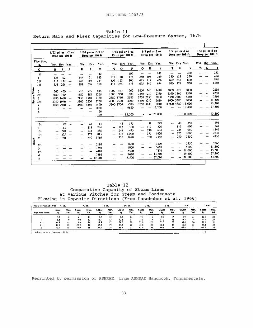
MIL-HDBK-1003/3
Reprinted by permission of ASHRAE, from ASHRAE Handbook, Fundamentals.
83

MIL-HDBK-1003/3
Reprinted by permission of ASHRAE, from ASHRAE Handbook, Fundamentals.
84

MIL-HDBK-1003/3
Reprinted by permission of ASHRAE, from ASHRAE Handbook, Fundamentals.
85
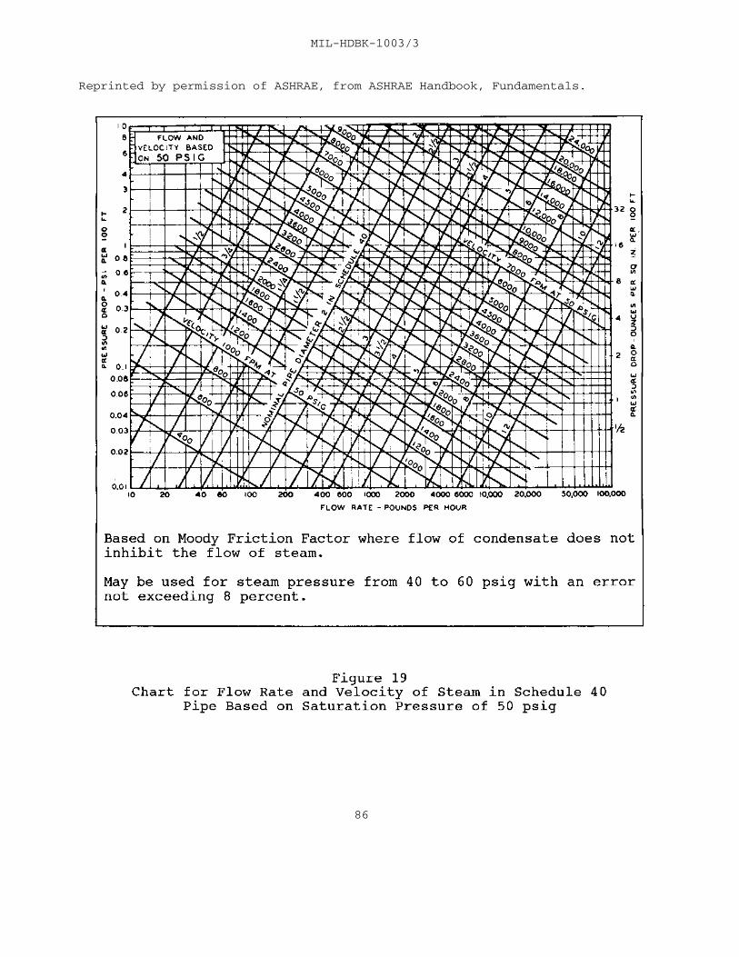
MIL-HDBK-1003/3
Reprinted by permission of ASHRAE, from ASHRAE Handbook, Fundamentals.
86

MIL-HDBK-1003/3
Reprinted by permission of ASHRAE, from ASHRAE Handbook, Fundamentals.
87

MIL-HDBK-1003/3
Reprinted by permission of ASHRAE, from ASHRAE Handbook, Fundamentals.
88
MIL-HDBK-1003/3
b) Do not use vacuum condensate returns. Since high pressure steamis hotter than low pressure steam, provide adequate cooling legs ofuninsulated steam pipe or a length of finned radiation between the last steammain takeoff and the drip assembly. Failure to do this will cause the hotcondensate to flash back into steam at the trap. Use vented flash tank as asolution. Refer to par. 7.3.3.5 for condensate pumps and flash tank.
7.3.3.2 Boiler. Refer to MIL-HDBK-1003/6.
7.3.3.3 Heat Exchanger. Refer to par. 7.2.2.5.
7.3.3.4 Steam Pressure Regulating Valves. See Figures 22 and 23 for pipingof steam pressure regulating assemblies, and note the following:
a) Sizing Pressure Regulating Valves
(1) Analyze flow required for maximum and minimum demand.
(2) Size the pressure regulating valve to handle peak flow. This will generally result in a valve body that is smaller than inlet supplyline size.
(3) If there is a big turndown ratio between minimum andmaximum flow, consider using two regulator valves in parallel, perhaps sizedfor 30 percent and 70 percent of the flow. Consider to flip the settings sothat the small regulator pilot maintains optimum downstream pressure in thesummer and the big regulator pilot is the lead controller in the winter.
(4) Look at the manufacturer's tables to see whether a twostage assembly should be used with two regulators in series. Sometimes thisis done anyway for redundancy in low pressure installations; with thedownstream regulator controlling to 5 psi, and a upstream regulator set at 7psi in case the downstream regulator cannot handle a flow surge.
b) Piping Pressure Regulating Valves
(1) Provide a bypass around the regulator with a globe valvethat has a tight shutoff seat. Size bypass to flow less than wide openfailure flow of the regulator, but not less than regulator design flow.
89

MIL-HDBK-1003/3
90

MIL-HDBK-1003/3
91

MIL-HDBK-1003/3
(2) Put a pressure gage immediately downstream ofthe regulator pilot tap. The pressure gage range should includethe upstream inlet pressure.
(3) Provide a relief valve on the downstream sidethat will handle 150 percent of the wide open failure flow ratingof the regulator. Set the relief valve higher than thedownstream operating pressure, and pipe the relief valvedischarge to a safe place.
(4) Provide shutoff valves on each side of theregulator assembly; with the low side shutoff valve downstream ofthe pilot tap.
(5) Locate the entire regulator assembly in anaccessible place.
7.3.3.5 Condensate Pumps and Flash Tank. Higher pressure steamcondensate is hotter than low pressure steam condensate. If thesystem is over 40 psi steam, always run the condensate through aflash tank before entering the receiver of the condensate pumpset. This prevents the condensate flashing to steam in thepumps. See Figure 24.
7.3.3.6 Steam Coils - General. Refer to par. 7.2.2.2 and themanufacturer's capacity tables for selection. See Figures 25 and26 for piping steam coils. Always provide steam traps for eachcoil section. Steam distributing coils feature a perforateddistributing header inside the main coil construction.
7.3.3.7 Steam Traps. In a steam system, steam traps should beprovided to remove condensate and gas from the steam supply assoon as it forms. Unless this is done:
a) A slug of condensate can harm the system.
b) Accumulation of CO gas can cause corrosion.2
See Table 14 for common types of steam traps and Figure 27 forpiping of a low pressure drip.
7.3.4 Boilers. Size the steam boiler in accordance with theASHRAE Equipment Handbook, and include building heating, processsteam, domestic water heating, and pickup loads. See Figure 28for piping a low pressure steam boiler.
92

MIL-HDBK-1003/3
93

MIL-HDBK-1003/3
94

MIL-HDBK-1003/3
95

MIL-HDBK-1003/3
Table 14 Common Types of Steam Traps
TYPE APPLICATION
Bellows Steady light loads in low pressure steam. Radiators, converters, etc.
Bimetallic High pressure steam where some condensate Thermostat backup is tolerable; Steam tracing, jacketed piping, heat transfer equipment, etc.
Float and Low pressure steam on temperature regulated Thermostatic coils; drips on steam mains; other large loads that vary where you cannot tolerate condensate backup.
Inverted High and low pressure steam. HVAC and drips Bucket on steam mains.
96

MIL-HDBK-1003/3
7.3.5 Freezing of Steam Coils - General. Care should be taken in bothdesign and construction of systems with steam heating coils to prevent coilfreeze-up. Two primary causes of coil freeze-up are: (1) stratification ofthe air entering the coil due to poor mixing of outside air and return air,and (2) buildup of condensate in the coil. While it is virtually impossibleto design a system with freeze-proof coils, careful consideration in thefollowing areas could air in minimizing coil freezing problems.
7.3.5.1 Freezing Due to Air Stratification. See Figure 29. In general,outside air and return air are mixed in proportions that will provide anaverage mixed air temperature above freezing. However, if the outside air andreturn air streams are not thoroughly mixed, stratification of air can occuracross the coil. This condition results in localized cold spots wheresub-freezing air contacts the coil and can cause freezing. Care should betaken when locating the steam coil and designing the
97

MIL-HDBK-1003/3
mixing chamber to ensure proper mixing of outside air and returnair. Figure 29 contains a sketch of a mixing plenum which is poorly designed for mixing of outside and return air and oneproperly designed to promote mixing of outside and return air.
7.3.5.2 Freezing Due to Buildup of Condensate in the Coil. SeeFigure 30 for coil piping to prevent freezing. There are anumber of oversights in design and installation that can lead tobuildup of condensate in a steam coil. These oversightsprimarily fall into the following categories:
a) Inappropriate Coil Selection. Many coil designspromote steam short circuiting - a phenomenon where steam takesthe path of least resistance through coil tubes that have theleast condensate flow. This increases the coil return headerpressure to the point where the condensate in other coil tubescannot drain properly. Coil designs have been developed to helpminimize problems like this. The single row distribution tubeand multi-row series flow coils minimize the potential forshort-circuiting and trapping condensate inside the coil. Thesecoil designs should be considered when designing a system wherethere is substantial risk of coil freezing.
b) Improper Installation. Even though the proper coilis selected, where the coil is not installed properly, freezingcan still occur. Many coils are installed in such a way thatgravity drainage is not possible. Though initially installedproperly, coils can move into an undesirable position throughbuilding settling or weakening of supports. Closely inspectingcoil installations with these problems in mind can help avoidproblems in this area.
c) Improper Venting, Vacuum Elimination, and SteamTrapping Practices. If a coil is not designed for proper ventingof noncondensables, vacuum elimination, and condensate removal, awell selected and installed coil can still experience problemswith condensate buildup. Consider carefully proper steam pipingpractices in these areas and consult available Navy and industryguidance.
d) Modulating Valves. Avoid using modulating valvesfor control of preheat coils.
e) Traps. Trap each coil separately. Coils seldomhave equal pressure drops.
98

MIL-HDBK-1003/3
99

MIL-HDBK-1003/3
100

MIL-HDBK-1003/3
7.3.6 Refrigerant Piping
7.3.6.1 General. This military handbook covers only directexpansion systems for HVAC systems. There is an entire ASHRAEHandbook devoted to food and industrial refrigeration. Refrigerant piping is slightly different from other pipingbecause refrigerant gas is difficult to contain, so that specialfittings (wrought copper or forged brass) and high melting pointsolder (1,000 degrees F) are needed to achieve a tight system,and provision must be made to ensure oil return to thecompressor.
7.3.6.2 Sizing. See the ASHRAE Handbook, Refrigeration forflow rate charts on sizing the liquid, suction, and hot gas lineswith various refrigerants.
7.3.6.3 Arrangement. See Figures 31 and 32 for refrigerantpiping arrangement.
101

MIL-HDBK-1003/3
102

MIL-HDBK-1003/3
103

MIL-HDBK-1003/3
Section 8: CONTROLS AND INSTRUMENTATION
8.1 General Requirements. See pars. 2.2.6 and 2.2.8 for anoverview of temperature controls and instrumentation. Anothersource of assistance that the designer may use is NFESC, CodeESC23 at Port Hueneme, California. NFESC is a Navy organizationthat has expertise in direct digital control (DDC) applications.
8.1.1 Choice of Controls. DDC is the control system ofchoice for HVAC systems. Consider the advantages of DDC for newand major renovation projects. Older conventional controlsystems may be specified for small buildings where DDC is notcost effective or where the customer refuses to accept DDC. Useof pneumatic controllers is discouraged because of the highmaintenance required to keep them functional. Existing pneumaticoperators may be reused, if in good operating condition, as partof a hybrid system with DDC sensors and controllers and thepneumatic operators.
8.1.1.1 A Guide to Choose Control Systems. Consider thefollowing when selecting the type of control system (digital,electric, analog electronic, or pneumatic):
a) Life cycle cost. In most cases, DDC will be thelowest cost on a life cycle cost basis. The first cost of DDC andconventional control systems may be comparable but DDC operatingand maintenance costs are significantly lower.
b) Customer preference of control type. The customermay feel that his personnel are better qualified to operate andmaintain a particular type control system. Repair parts may bean important consideration.
8.1.1.2 Factors to Select Control Systems. Control selectionmay be determined by several factors as follows:
a) DDC systems use stand-alone digital controllers,distributed throughout the building to provide control of HVACfunctions. The digital controller replaces conventional receivercontrollers, thermostats, switches, relays, and auxiliarydevices. Sensors are wired directly to the digital controller,which performs the control logic in software, and outputs acontrol signal directly to the actuator or relay. Terminalcontrol units control individual terminal HVAC equipment, such asVAV boxes, fan coil units, and heat pumps. Distributed controlrefers to locating the digital controllers near the equipmentbeing controlled.
104

MIL-HDBK-1003/3
b) DDC systems require less maintenance thanconventional control systems. With a personal controller (PC)interface workstation, HVAC mechanics can quickly troubleshootHVAC problems. DDC systems efficiently operate building HVACsystems by providing accurate sensing, maintaining setpoints, andoperating in the designed sequence.
c) One disadvantage of DDC is that DDC systems fromdifferent manufacturers have different operating systems whichare proprietary and will not communicate with each other. Insome cases, this makes competitive bids for additions difficult.
d) Consider specifying DDC in the followingsituations:
(1) In most new construction,
(2) In a major retrofit of HVAC systems,
(3) When complex or numerous HVAC systems areincluded in the design,
(4) In buildings over 20,000 square feet,
(5) When remote or local workstation monitoringand troubleshooting of HVAC equipment is desired, and
(6) When the customer desires DDC.
e) Acceptance of DDC by the user's operation andmaintenance personnel is extremely important. If not soaccepted, DDC should not be specified. The project managershould directly contact station personnel to make thisdetermination of acceptance.
f) Consider conventional electric, analog electronic,or pneumatic control systems when the following apply:
(1) Small buildings where DDC is not costeffective,
(2) When package air handling units are specified,and
(3) When the customer or maintenance will notsupport DDC.
8.1.2 Designing DDC Systems. Design DDC systems using thefollowing guidance:
105

MIL-HDBK-1003/3
a) Keep the input and output points to the minimumnumber required for HVAC control and efficient buildingoperation. Follow the recommended point guidance provided inpar. 8.2. Follow the principle to "Keep it Simple."
b) Use standard control sequences for similar HVACcontrol system applications.
c) Show the following on control drawings as aminimum:
(1) Flow diagram schematic of each mechanicalsystem showing sensors, equipment, and operators.
(2) Individual point list description for eachmechanical system.
(3) Electrical ladder diagram for each electricalcircuit controlled.
(4) Operating parameters - controller setpointsand time schedules.
(5) Detailed sequence of operation.
d) Use direct connection of temperature sensors whenpossible. Use only precision thermistors (10,000 ohms) for roomsensing and 1000 ohm platinum RTDs for HVAC unit sensing.
e) Use room zone temperature sensors with pushbuttonoverride and setpoint adjustment integral to the sensor.
f) Do not modify the chiller microprocessor systemsupplied with the equipment. Control and safety functions shouldbe the chiller manufacturer's responsibility. The DDC systemshould only enable or disable the chiller, chilled water pump,condenser water pump, and in some cases chilled water andcondenser water reset. For chillers 150 tons and larger, providean RS-485 communication between the chiller microprocessor andthe DDC system.
g) Do not modify the boiler microprocessor systemsupplied with the equipment. Control and safety functions shouldbe the boiler manufacturer's responsibility. Design hot watersystems to maintain the boiler manufacturer's minimum temperature when in operation but vary the hot water supply temperature asrequired to meet the building's requirements.
106

MIL-HDBK-1003/3
h) Connect steam, high temperature hot water, gas, andelectric meters to the DDC for remote monitoring of energy use ofthe building.
8.2 Standard Sequences of Operations
8.2.1 General Requirements. These requirements shall applyto primary HVAC systems unless modified herein. The sequencesdescribe actions of the control system in one direction of changein the HVAC process analog variable, such as temperature,humidity, or pressure. The reverse sequence shall occur whendirection of change is reversed unless specifically modified.
8.2.2 Operation of HVAC System. Equipment shall be operatedin the optimized start, occupied, or unoccupied modes.
a) The optimized start mode energizes the equipment atmaximum capacity at the latest time required for heating up (orcooling down) the space to normal occupied temperatureconditions.
b) The occupied mode maintains the occupied conditionsunder all load variations while providing required ventilation. Supply fan operates continuously.
c) The unoccupied mode cycles the equipment tomaintain a minimum heating temperature (or a maximum coolingtemperature) in the space while providing no ventilation.
8.2.3 Operation of Outside Air, Return Air, and Exhaust(Relief) Air Dampers
a) Optimized Start Mode: Outside air and exhaust airdampers are closed and return air dampers are opened.
b) Occupied Mode: Outside air dampers are opened tothe minimum ventilation air position. If an economizer outsideair cycle is provided, the outside air, return air, and exhaustair dampers are automatically controlled. An outdoor air drybulb sensor disables the economizer cycle and maintains minimumventilation air when the outside air dry bulb temperature exceedsthe changeover point.
c) Unoccupied Mode: Outside air and exhaust airdampers are closed and return air dampers are opened.
8.2.4 Operation of Filtration System. Differential pressuresensor measuring static pressure drop across the filter shallinitiate alarm when pressure drop exceeds recommended value.
107
MIL-HDBK-1003/3
8.2.5 Operation of Freeze Protection. A freezestat with an extended surface sensing element, located ahead of the chilledwater coil, shall stop the supply fan, return system componentsto their fail-safe position, and initiate a low-temperature alarm if the temperature at any point of the sensing element fallsbelow the setpoint. Normal operation will occur only after thefreezing condition is corrected and the freezestat is manuallyreset.
8.2.6 Operation of Smoke Detectors. Duct type smokedetectors located in the supply fan discharge air duct and in thereturn air duct (as required by NFPA) shall stop the supply fan,return system components to their fail-safe position, and shallactivate the smoke alarm if either detector senses the presenceof smoke. Normal operation will occur only after the smoke iscleared and the detector(s) is manually reset.
8.2.7 Operation of Chilled Water Coil Discharge Control. Adry bulb temperature sensor located in the chilled water coildischarge air shall, on a rise in temperature, first, graduallyclose the preheat coil valve, next, gradually open the outsideair damper from its minimum ventilation air position whilesimultaneously gradually close the return air damper (ensurethorough mixing) and gradually opening the exhaust air damper,and then gradually open the chilled water coil valve. An outdoorair dry bulb sensor disables the economizer cycle and maintainsminimum ventilation air when outside air dry bulb temperatureexceeds the changeover point.
8.2.8 Operation of Preheat Coil Control. (Where required byoutdoor design temperatures and ventilation air requirements.) A dry bulb temperature low limit sensor located in the mixed air(ensure thorough mixing) shall, on a fall in temperature, gradually open the preheat coil valve. Primary control shall be sequenced by the chilled water coil discharge sensor or supplyair sensor.
8.2.9 Operation of Heating Coil Control. A dry bulbtemperature sensor located in the heating coil discharge airshall, on a rise in dry bulb air temperature, gradually close theheating coil valve.
8.2.10 Operation of Space Control (Single Zone Unit). A roomtype dry bulb temperature sensor located in the most criticalspot shall, on a rise in dry bulb temperature in the space, firstgradually close the heating coil valve, next gradually close thepreheat coil valve, then gradually open the outside air damperfrom its minimum ventilation air position while simultaneouslygradually close the return air damper (ensure thorough mixing)
108

MIL-HDBK-1003/3
and gradually opening the exhaust air damper, and finallygradually open the chilled water coil valve. A dry bulbtemperature low limit sensor located in the mixed air (ensurethorough mixing) shall, on a fall in temperature, gradually openthe preheat coil valve. An outdoor air dry bulb sensor disablesthe economizer cycle and maintains minimum ventilation air when outside air dry bulb temperature exceeds the changeover point.
8.2.11 Operation of Space Control (Multizone Unit). A roomtype dry bulb temperature sensor located in the most criticalspot shall, on a rise in dry bulb temperature in the space,gradually open the cold deck damper while simultaneouslygradually close the hot deck damper.
8.2.12 Operation of Space Control (VAV Terminal Unit -Pressure Dependent). A room type dry bulb temperature sensorlocated in the most critical spot shall, on a rise in dry bulbtemperature in the space, gradually open the VAV terminal boxcold air valve.
8.2.13 Operation of Supply Duct Pressure Control. A supplyduct static pressure sensor located two-thirds the distance fromthe fan of the length of the longest supply duct run shall, on arise in static pressure, gradually reduce the speed of theelectric motor variable speed drive and close the fan vortexdamper. A high-limit duct static pressure sensor located at thefan discharge shall override the supply duct static pressuresensor to limit pressures to design values.
8.3 Single Zone Unit Sequence of Operations (Sample). SeeFigure 33 and Table 15.
a) General: Sequences describe actions of the controlsystem in one direction of change in the HVAC process analogvariable, such as temperature, humidity, or pressure. Reversesequence shall occur when direction of change is reversed unlessspecifically modified.
b) Optimized Start Mode: Energize equipment atmaximum capacity at the latest time required for heating up (orcooling down) the space to normal occupied temperatureconditions. Outside air and exhaust air dampers are closed andreturn air dampers are opened.
c) Occupied Mode: Maintain occupied conditions underload variations while providing required ventilation. Supply fanoperates continuously. Outside air dampers are opened to theminimum ventilation air position. If an economizer outside aircycle is provided, the outside air, return air, and exhaust air
109

MIL-HDBK-1003/3
dampers are automatically controlled. An outdoor air dry bulbsensor disables the economizer cycle and maintains minimumventilation air when outside air dry bulb temperature exceeds thechangeover point.
d) Unoccupied Mode: Cycle the equipment to maintain minimum heating temperature (or maximum cooling temperature) inthe space while providing no ventilation. Outside air andexhaust air dampers are closed and return air dampers are opened.
e) Maintenance and Safety Mode: A differentialpressure sensor measuring static pressure drop across the filtershall initiate an alarm when the pressure drop exceeds therecommended value.
A freezestat with extended surface sensing elementlocated ahead of the chilled water coil shall stop the supplyfan, return system components to their fail-safe position, andinitiate a low-temperature alarm if the temperature at any pointof the sensing element falls below the setpoint. Normaloperation shall occur only after the freezing condition iscorrected and the freezestat is manually reset.
f) Room Control Mode: A room type dry bulbtemperature sensor located in the most critical spot shall, on arise in dry bulb temperature in the space, first gradually closethe heating coil valve, next gradually close the preheat coilvalve, then gradually open the outside air damper from itsminimum ventilation air position while simultaneously graduallyclose the return air damper (ensure thorough mixing) andgradually opening the exhaust air damper, and finally graduallyopen the chilled water coil valve. A dry bulb temperature lowlimit sensor located in the mixed air (ensure thorough mixing)shall, on a fall in temperature, gradually open the preheat coilvalve. A dry bulb temperature low limit sensor located in thesupply air shall, on a fall in temperature, gradually open theheating coil valve. An outdoor air dry bulb sensor disables theeconomizer cycle and maintains minimum ventilation air whenoutside air dry bulb temperature exceeds the changeover point.
8.4 Multizone Unit Sequence of Operation (Sample). SeeFigure 34 and Table 16.
a) General: Sequences describe actions of the controlsystem in one direction of change in the HVAC process analogvariable, such as temperature, humidity, or pressure. Reversesequence shall occur when direction of change is reversed unlessspecifically modified.
110

MIL-HDBK-1003/3
111

MIL-HDBK-1003/3
112

LOOP CONTROL DEVICE DEVICE ADDITIONALFUNCTION NUMBER FUNCTION SETPOINT RANGE PARAMETERSROOM ZONE DA-XX01, DAMPER -- 4-20 ma MIN.O.A.TEMPERATURE 02, 03 ACTUATOR XXXX CFM -- OUTDOOR AIR 65 F -- SOFTWAREO
DB HI LIMIT POINT TS-XX01 MIXED AIR 55 F 30-130 F --O o
LOW LIMIT TEMPERATURE SENSOR VLV-XX01 PREHEAT COIL -- 4-20 ma CV-10 VALVE CLOSE AGAINST 16 PSIG TS-XX02 SUPPLY AIR 55 F 40-140 F --O o
VLV-XX02 HEATING COIL -- 4-20 ma CV-12 VALVE CLOSE AGAINST 16 PSIG VLV-XX03 COOLING COIL -- 4-20 ma CV-20 VALVE CLOSE AGAINST 20 PSIG TS-XX03 ROOM ZONE H-70 F 50-100 F WITHO o
TEMPERATURE C-76 F SETPOINTo
SENSOR N-55 F ADJUST-o
MENT & OVERRIDE SWITCH
SAFETY & TSL-XX01 LOW 35 F -- --o
MAINTENANCE TEMPERATURE PROTECTION THERMOSTAT SD-XX01 SUPPLY AIR -- -- -- SMOKE DETECTOR SD-XX02 RETURN AIR -- -- -- SMOKE DETECTOR DP-XX01 FILTER STATUS 0.5 IN. 0-2 IN. -- DIFFERENTIAL W.G. W.G. PRESSURE
MIL-HDBK-1003/3
Table 15Equipment for Single Zone HVAC Control System XX
113

LOOP CONTROL DEVICE DEVICE ADDITIONALFUNCTION NUMBER FUNCTION SETPOINT RANGE PARAMETERS
SAFETY & TS-XX04 RETURN AIR -- 50-100 F --O
MAINTENANCE TEMPERATURE(CONT’D) SENSORSUPPLY FAN R-XX01 SUPPLY FAN -- -- -- START RELAY CS-XX01 SUPPLY FAN -- -- -- CURRENT SENSOR
MIL-HDBK-1003/3
Table 15 (Continued)Equipment for Single Zone HVAC Control System XX
114

MIL-HDBK-1003/3
115

MIL-HDBK-1003/3
Table 16 Equipment for Multizone HVAC Control System XX
LOOP CONTROL DEVICE DEVICE ADDITIONAL FUNCTION NUMBER FUNCTION SETPOINT RANGE PARAMETERS
COLD DECK DA-XX01, DAMPER -- 4-20 ma MIN.O.A. TEMPERATURE 02, 03 ACTUATOR XXXX CFM -- OUTDOOR AIR 65 deg F -- SOFTWARE DB HI LIMIT POINT TS-XX01 MIXED AIR 55 deg F 30-130 deg F -- LOW LIMIT TEMPERATURE SENSOR 116

LOOP CONTROL DEVICE DEVICE ADDITIONALFUNCTION NUMBER FUNCTION SETPOINT RANGE PARAMETERS
COLD DECK VLV-XX01 PREHEAT COIL -- 4-20 ma CV-10TEMPERATURE VALVE CLOSE(CONT’D) AGAINST 16 PSIG TS-XX02 COLD DECK 55 F 40-140 F --O o
TEMPERATURE SENSOR VLV-XX02 COOLING COIL -- 4-20 ma CV-20 VALVE CLOSE AGAINST 20 PSIGHOT DECK TS-XX03 HOT DECK 180 F 40-240 F o o
TEMPERATURE TEMPERATURE SENSOR VLV-XX03 HEATING COIL -- 4-20 ma CV-12 VALVE CLOSE AGAINST 16 PSIGROOM SENSORS TS-XX04 ROOM H-70 F 50-100 F WITHO o
(MULTIPLE) TEMPERATURE C-76 F SETPOINTo
SENSORS N-55 F ADJUST-o
MENT & OVERRIDE SWITCH DA-XX04 ZONE DAMPER -- 4-20 ma ONE PER ACTUATORS ZONESAFETY & TSL-XX01 LOW 35 F -- --o
MAINTENANCE TEMPERATURE PROTECTION THERMOSTAT SD-XX01 SUPPLY AIR -- -- -- SMOKE DETECTOR SD-XX02 RETURN AIR -- -- -- SMOKE DETECTOR DP-XX01 FILTER STATUS 0.5 IN. 0-2 IN. -- DIFFERENTIAL W.G. W.G. PRESSURE TS-XX04 RETURN AIR -- 50-100 F --O
TEMPERATURE SENSOR
MIL-HDBK-1003/3
Table 16 (Continued)Equipment for Multizone HVAC Control System XX
117

LOOP CONTROL DEVICE DEVICE ADDITIONALFUNCTION NUMBER FUNCTION SETPOINT RANGE PARAMETERS
SAFETY & TS-XX04 RETURN AIR -- 50-100 F --o
MAINTENANCE TEMPERATURE(CONT’D) SENSORSUPPLY FAN R-XX01 SUPPLY FAN -- -- -- START RELAY CS-XX01 SUPPLY FAN -- -- -- CURRENT SENSOR
MIL-HDBK-1003/3
Table 16 (Continued)Equipment for Multizone HVAC Control System XX
b) Optimized Start Mode: Energize equipment atmaximum capacity at the latest time required for heating up (orcooling down) the space to normal occupied temperatureconditions. Outside air and exhaust air dampers are closed andreturn air dampers are opened.
c) Occupied Mode: Maintain occupied conditions underall load variations while providing required ventilation. Supplyfan operates continuously. Outside air dampers are opened to theminimum ventilation air position. If an economizer outside aircycle is provided, the outside air, return air, and exhaust airdampers are automatically controlled. An outdoor air dry bulbsensor disables the economizer cycle and maintains minimumventilation air when outside air dry bulb temperature exceeds thechangeover point.
d) Unoccupied Mode: Cycle the equipment to maintain minimum heating temperature (or maximum cooling temperature) inthe space while providing no ventilation. Outside air andexhaust air dampers are closed and return air dampers are opened.
e) Maintenance and Safety Mode: A differentialpressure sensor measuring static pressure drop across the filter,shall initiate an alarm when the pressure drop exceeds therecommended value.
A freezestat with extended surface sensing elementlocated ahead of the chilled water coil shall stop the supplyfan, return system components to their fail-safe position, andinitiate a low-temperature alarm if the temperature at any point
118

MIL-HDBK-1003/3
of the sensing element falls below the setpoint. Normaloperation will occur only after the freezing condition iscorrected and the freezestat is manually reset.
f) Chilled Water Coil Discharge Air Mode: A dry bulbtemperature sensor located in the chilled water coil dischargeair shall, on a rise in temperature, first gradually close thepreheat coil valve, next gradually open the outside air damperfrom its minimum ventilation air position while simultaneouslygradually close the return air damper (ensure thorough mixing)and gradually open the exhaust air damper, and then graduallyopen the chilled water coil valve. A dry bulb temperature lowlimit sensor located in the mixed air (ensure thorough mixing)shall, on a fall in temperature, gradually open the preheat coilvalve. An outdoor air dry bulb sensor disables the economizercycle and maintains minimum ventilation air when outside air drybulb temperature exceeds the changeover point.
g) Heating Coil Discharge Air Mode: A dry bulbtemperature sensor located in the heating coil discharge airshall, on a rise in dry bulb air temperature, gradually close theheating coil valve.
h) Room Control Mode: A room type dry bulbtemperature sensor located in the most critical spot shall, on arise in dry bulb temperature in the space, gradually open thecold deck damper while simultaneously gradually close the hotdeck damper.
8.5 Variable Air Volume (VAV) Unit Sequence of Operation (Sample). See Figure 35 and Table 17.
a) General: Sequences describe actions of the controlsystem in one direction of change in the HVAC process analogvariable, such as temperature, humidity, or pressure. Reversesequence shall occur when direction of change is reversed unlessspecifically modified.
b) Optimized Start Mode: Energize equipment atmaximum capacity at the latest time required for heating up (orcooling down) the space to normal occupied temperatureconditions. Outside air and exhaust air dampers are closed andreturn air dampers are opened. Fans of series type VAV terminalunits shall start.
c) Occupied Mode: Maintain occupied conditions underall load variations while providing required ventilation. Supplyfan operates continuously. Outside air dampers are opened to theminimum ventilation airflow by the air monitoring unit for all
119

MIL-HDBK-1003/3
values of supply fan flow. If an economizer outside air cycle isprovided, the outside air, return air, and exhaust air dampersare automatically controlled. An outdoor air dry bulb sensordisables the economizer cycle and maintains minimum ventilationair when the outside air dry bulb temperature exceeds thechangeover point. Fans of series type VAV terminal units shallrun continuously.
d) Unoccupied Mode: Cycle the VAV terminal units atmaximum heating capacity to maintain minimum heating temperaturein the space while providing no ventilation. Outside air andexhaust air dampers are closed and return air dampers are opened.
e) Maintenance and Safety Mode: A differentialpressure sensor measuring static pressure drop across the filtershall initiate an alarm when the pressure drop exceeds therecommended value.
A freezestat with extended surface sensing elementlocated ahead of the chilled water coil shall stop the supplyfan, return system components to their fail-safe position, andinitiate a low-temperature alarm if the temperature at any pointof the sensing element falls below the setpoint. Normaloperation will occur only after the freezing condition iscorrected and the freezestat is manually reset.
f) Supply Fan Discharge Air Mode: A dry bulbtemperature sensor located in the supply air fan discharge airshall, on a rise in temperature, first gradually close thepreheat coil valve, next gradually open the outside air damperfrom its minimum ventilation air position while simultaneouslygradually close the return air damper (ensure thorough mixing)and gradually open the exhaust air damper, and then graduallyopen the chilled water coil valve. A dry bulb temperature lowlimit sensor located in the mixed air (ensure thorough mixing)shall, on a fall in temperature, gradually open the preheat coilvalve. An outdoor air dry bulb sensor disables the economizercycle and maintains minimum ventilation air when the outside airdry bulb temperature exceeds the changeover point.
g) Supply Duct Static Pressure Mode: A supply ductstatic pressure sensor located two-thirds the distance from thefan of the length of the longest supply duct run shall, on a risein static pressure, gradually reduce the speed of the electricmotor variable speed drive and close the fan vortex damper. Ahigh-limit duct static pressure sensor located at the fandischarge shall override the supply duct static pressure sensorto limit pressures to design values.
120

MIL-HDBK-1003/3
121

MIL-HDBK-1003/3
122

LOOP CONTROL DEVICE DEVICE ADDITIONALFUNCTION NUMBER FUNCTION SETPOINT RANGE PARAMETERS
SUPPLY AIR DA-XX01, DAMPER -- 4-20 ma --TEMPERATURE 02, 03 ACTUATOR AMU-XX01 AIR MONI- -- -- MIN. O.A. TORING UNIT XXXX CFM -- OUTDOOR AIR 65 F -- SOFTWAREO
DB HI LIMIT POINT TS-XX01 MIXED AIR 55 F 30-130 F --O o
LOW LIMIT TEMPERATURE SENSOR VLV-XX01 PREHEAT COIL -- 4-20 ma CV-10 VALVE CLOSE AGAINST 16 PSIG TS-XX02 SUPPLY AIR 55 F 40-140 F --O o
FAN DISCHARGE TEMPERATURE SENSOR VLV-XX02 COOLING COIL -- 4-20 ma CV-20 VALVE CLOSE AGAINST 20 PSIGSUPPLY DUCT PS-XX01 SUPPLY DUCT 1.5 IN. 0-5 IN. --
STATIC STATIC W.G. W.G.PRESSURE PRESSURE SENSOR PS-XX02 FAN DISCHARGE 3.5 IN. 0-5 IN. -- HIGH LIMIT W.G. W.G. STATIC PRESSURE SENSOR SFC-XX01 SUPPLY FAN -- 4-20 ma VARIABLE SPEED CONTROLLERSAFETY & TSL-XX01 LOW 35 F -- --o
MAINTENANCE TEMPERATURE PROTECTION THERMOSTAT
MIL-HDBK-1003/3
Table 17Equipment for VAV HVAC Control System XX
123

LOOP CONTROL DEVICE DEVICE ADDITIONALFUNCTION NUMBER FUNCTION SETPOINT RANGE PARAMETERS
SAFETY & SD-XX01 SUPPLY AIR -- -- --MAINTENANCE SMOKE DETECTOR(CONT’D) SD-XX02 RETURN AIR -- -- -- SMOKE DETECTOR DP-XX01 FILTER STATUS 0.5 IN. 0-2 IN. -- DIFFERENTIAL W.G. W.G. PRESSURE TS-XX04 RETURN AIR -- 50-100 F --O
TEMPERATURE SENSORSUPPLY FAN R-XX01 SUPPLY FAN -- -- -- START RELAY CS-XX01 SUPPLY FAN -- -- -- CURRENT SENSORROOM SENSORS TS-XX04 ROOM H-70 F 50-100 F WITHO o
(MULTIPLE) TEMPERATURE C-76 F SETPOINTo
SENSORS N-55 F ADJUST-o
MENT & OVERRIDE SWITCH DA-XX04 VAV TERMINAL -- 4-20 ma ONE PER BOX COLD AIR ZONE VALVE VLV-XX03 VAV HEATING -- 4-20 ma CV VARIES COIL VALVE CLOSE AGAINST 16 PSIG R-XX02 VAV TERMINAL -- -- -- BOX FAN START RELAY
MIL-HDBK-1003/3
Table 17 (Continued)Equipment for VAV HVAC Control System XX
h) Room Control Mode: A room type dry bulbtemperature sensor located in the most critical spot shall, on arise in dry bulb temperature in the space, gradually open the VAVterminal box cold air valve.
8.6 Commissioning Procedures
8.6.1 Functional Performance Test. Participate in thefunctional performance test as described in ASHRAE Guideline 1.
124

MIL-HDBK-1003/3
Verify and document the performance of the control system asrequired by the Commissioning Plan prepared by the CommissioningAuthority. Final positions of manual balancing dampers andvalves shall be marked on the device. Permanently record, onsystem equipment schedule, the final setting of controllerproportional, integral, and derivative constant settings in unitsand terminology specific to the controller. This will becomepart of the O&M manual.
8.6.2 Preparation for Acceptance Testing. Execute a detailedstatic and functional checkout procedure to ensure that systemsare ready for functional performance testing.
8.6.3 System Static Checkout
8.6.3.1 Observation. Provide a detailed inspection to assurethat all equipment is properly mounted, sensors are properlyinstalled and connected, control devices are properly installed,and controllers and control devices are properly connected.
8.6.3.2 Calibration. Check, verify, and calibrate all sensorsincluding those sensors that are "factory calibrated." Perform atwo-point accuracy check of the calibration of each HVAC controlsystem sensing element by comparing the HVAC controller readoutto the actual value of the variable measured at the sensingelement or airflow measurement station location. Use digitalindicating test instruments, such as digital thermometers,motor-driven psychrometers, and tachometers. Test instrumentsshall be at least twice as accurate as the specified sensingelement-to-controller readout accuracy. Calibration of testinstruments shall be traceable to National Institute of Standardsand Technology (NIST) standards. In the shutdown condition,calibration checks shall verify that the sensing element-to-controller readout accuracies at two points are within thespecified product accuracy tolerances. If not, re-calibrate orreplace the inaccurate device and repeat the calibration check.
a) Check insertion temperature and immersiontemperature sensing element and transmitter-to-controller readoutcalibration accuracy at one physical location along the axis ofthe sensing element.
b) Check averaging temperature sensing element andtransmitter-to-controller readout calibration accuracy every 2feet along the axis of the sensing element in the proximity ofthe sensing element, for a maximum of 10 readings. Then averagethese readings.
125

MIL-HDBK-1003/3
c) Verify space type sensors by placing the testinstrument as close as possible to the sensor to measureidentical conditions. Maintain the test for a sufficient lengthto ensure achieving stable conditions.
8.6.3.3 Operation
a) Each controller shall be configured for itsspecified service. Verify each sequence of operation for eachHVAC system and subsystem. Verify that each controlled deviceresponds to the proper controller, in the proper manner, and atthe proper time. Verify the fail-safe position for eachcomponent of the system.
b) Set the time schedule of controllers in accordancewith the sequence of operation and the established time schedule.
8.6.4 System Dynamic Checkout. Perform weather-dependenttest procedures that cannot be performed by simulation in theappropriate climatic season. When simulation is used, verify theactual results in the appropriate season.
a) Use the controllers' manual-automatic switches asthe means of manipulating control devices such as dampers andvalves to check operation and to effect stable conditions, priorto making measurement checks.
b) Perform a controller tuning procedure, which shallconsist of setting the initial proportional, integral, andderivative (PID) mode constants, controller setpoints, andlogging the settings. Tuning shall be self-tuning operation bythe controller unless manual tuning is necessary.
8.6.4.1 Controller Manual-Tuning Procedure. A controllermanual tuning procedure is described in three steps using aconstant temperature setpoint controller as an example.
a) Step 1. This step shall consist of the following:
(1) Index the controller manual-automatic switchto the automatic position, and set the integral and derivativemode constants to zero.
(2) Set the proportional mode constant to aninitial setting of 8 percent. This corresponds to a 2.0 ma perdegree F or a 1.5 psig per degree F proportional controlleroutput change for a 100-degree F span. This causes thecontroller output signal to vary from zero output to full outputfor an input signal change representing an 8-degree F change.
126

MIL-HDBK-1003/3
(3) Controllers for other variables, such asrelative humidity and static pressure, shall have theirproportional mode constants set initially in a similar manner foran achievable output range proportional to the transmitter span.
b) Step 2. This step shall consist of the following:
(1) Set the controller temperature setpoint at anyachievable temperature. Observe the controller output andtransmitter input.
(2) If the transmitter input continuouslyoscillates above and below the setpoint without settling at afixed value, or if such oscillation increases, the proportionalmode constant is too small.
(3) If the proportional mode constant is toosmall, increase it in steps until the transmitter input indicatesstable control at any temperature, if the controller output isnot at either extreme of the output range.
(4) If the temperature control point slowly driftstoward or away from the controller setpoint, the proportionalmode constant is too large. Decrease its setting in steps untiloscillations occur as described in the preceding paragraphs, andthen increase the setting until stable control occurs.
(5) Introduce a step change in controllersetpoint. This should cause the controller to overshoot thesetpoint slightly, with each subsequent overshoot peak valuedecreasing by a factor of two-thirds until stable control isachieved at, above, or below the setpoint.
(6) Increase the integral mode constant setting insmall steps, and introduce setpoint changes until control pointand controller setpoint coincide at stable control. This shouldhappen consistently after a setpoint change within a short time,such as 5 to 10 minutes.
c) Step 3. This step shall consist of the following:
(1) Unless the HVAC process variable changesrapidly, the derivative mode constant setting can remain at zero. This is usually the case for most HVAC applications.
(2) If derivative control is needed, graduallyincrease the derivative mode constant.
127

MIL-HDBK-1003/3
(3) Introduce step changes in controller setpoint,and adjust the derivative mode constant setting until stablecontrol is achieved.
d) Step 4. After the controller manual tuningprocedure is complete, set the controller at the predeterminedsetpoint in the design drawings.
8.6.5 Procedures for Single Zone Control System (Sample)
a) System Inspection. Observe the HVAC system in itsshutdown condition. Check to see that power (and main air) is(are) available for the HVAC system control devices. Check tosee that the outside air damper, relief air damper, heating coilvalve, and cooling coil valve are closed, and that the return airdamper is open. Check to see that the preheat coil valve isbeing controlled by the mixed air low limit controller.
b) Calibration Accuracy Check. Check with HVAC systemin the shutdown condition. Take readings with a digitalthermometer at each temperature sensing element location. Readeach controller display, and log the thermometer and controllerdisplay readings. Check the calibration accuracy of the sensingelement to controller readouts for outside air, return air, mixedair, and supply air temperatures.
c) Actuator Range Adjustments. Apply a signal to eachactuator, by placing the controller manual-automatic switch inthe manual position. Verify visually the proper operation of theactuators for dampers and valves. Vary the signal from 4 ma (or3 psig) to 20 ma (or 15 psig), and verify that the actuatorstravel from zero stroke to full stroke within the signal range. Observe that sequenced and parallel operated actuators move fromzero stroke to full stroke in the proper direction, and move theconnected device in the proper direction from one extremeposition to the other. Example: Normally closed actuators areclosed at 4 ma (or 3 psig) and are open at 20 ma (or 15 psig). Log the signal levels that move the controlled device to itsextreme positions.
d) Control System Startup
(1) With the fan ready to start, apply theoptimized start mode command, and observe that the designatedsupply fan starts. Observe that the outside air and relief airdampers are closed, the return air damper is open, and theheating coil valve and preheat coil valve (cooling coil valve)are in the warm up (cool down) position. Change the command tooccupied mode and observe that the outside air damper, return air
128

MIL-HDBK-1003/3
damper, relief air damper, heating coil valve, preheat coilvalve, and chilled water valve are in control, by changing thecontroller output.
(2) Apply the minimum outside air mode signal. Observe that the outside air damper opens to the minimumposition.
(3) Index the mixed air low limit temperaturecontroller manual-automatic switch to the manual position. Perform the two-point calibration accuracy check of sensingelement-to-controller readout. Index the mixed air low limittemperature controller manual-automatic switch to the automaticposition. Change the controller output to open the preheat coilvalve slightly. Perform the controller tuning procedure. Setthe controller at the predetermined temperature setpoint. Applythe economizer mode input signal, and observe that the outsideair, return air, and relief air dampers are under control. Indexthe supply air low limit temperature controller manual-automaticswitch to the manual position. Perform the two-point calibrationaccuracy check of sensing element-to-controller readout. Indexthe supply air low limit temperature controller manual-automaticswitch to the automatic position. Change the controller outputto open the heating coil valve slightly. Perform the controllertuning procedure. Set the controller at the predeterminedtemperature setpoint. Index the room temperature controllermanual-automatic switch to the manual position, and perform thetwo-point calibration accuracy check of sensing element-to-controller readout. Index the controller manual-automatic switchto the automatic position, and perform the controller tuningprocedure. Set the controller at the temperature setpoint asshown.
(4) Apply an unoccupied mode signal, and observethat the HVAC system shuts down, and the control system assumesthe specified shutdown conditions. Raise the night thermostattemperature setting and observe that the HVAC system starts. Lower the setting and observe that the HVAC system stops. Setthe night thermostat at the predetermined setting.
(5) With the HVAC system running, simulate afilter differential pressure switch input signal at the device. Observe that the filter alarm is activated. Set the differentialpressure switch at the predetermined setpoint.
(6) With the HVAC system running, simulate a lowtemperature condition at the freezestat. Observe HVAC systemshutdown and that the low temperature alarm is activated. Set
129

MIL-HDBK-1003/3
the thermostat at the predetermined setpoint. Restart the HVACsystem by manual reset, and observe that the alarm isdeactivated.
(7) With the HVAC system running, simulate a smokedetector trip input signal at each detector, and observe andverify operation as described in the sequence of operation. Perform simulation without false-alarming any life safetysystems. Observe that the HVAC system shuts down and the alarmis activated. Reset the detectors. Restart the HVAC system bymanual reset, and observe that the alarm is deactivated.
8.6.6 Procedures for Multizone Control System (Sample)
a) System Inspection. Observe the HVAC system in itsshutdown condition. Check to see that power (and main air) is(are) available for the HVAC system control devices. Check tosee that the outside air damper, relief air damper, heating coilvalve, and cooling coil valve are closed, and that the return airdamper is open. Check to see that the preheat coil valve isbeing controlled by the mixed air low limit controller.
b) Calibration Accuracy Check. Check with the HVACsystem in the shutdown condition: take readings with a digitalthermometer at each temperature sensing element location; readeach controller display, and log the thermometer and controllerdisplay readings; and check the calibration accuracy of thesensing element to controller readouts for outside air, returnair, mixed air, cold deck air, and hot deck air temperatures.
c) Actuator Range Adjustments. Apply a signal to eachactuator by placing the controller manual-automatic switch in themanual position. Verify visually the proper operation of theactuators for dampers and valves. Vary the signal from 4 ma (or3 psig) to 20 ma (or 15 psig), and verify that the actuatorstravel from zero stroke to full stroke within the signal range. Observe that sequenced and parallel operated actuators move fromzero stroke to full stroke in the proper direction, and move theconnected device in the proper direction from one extremeposition to the other. Example: Normally closed actuators areclosed at 4 ma (or 3 psig) and are open at 20 ma (or 15 psig). Log the signal levels that move the controlled device to itsextreme positions.
d) Control System Startup
(1) With the fan ready to start, apply theoptimized start mode command, and observe that the designatedsupply fan starts. Observe that outside air and relief air
130

MIL-HDBK-1003/3
dampers are closed, the return air damper is open, and theheating coil valve and preheat coil valve (cooling coil valve)are in the warm-up (cool down) position. Change the command tooccupied mode and observe that the outside air damper, return airdamper, relief air damper, heating coil valve, preheat coilvalve, and chilled water valve are in control, by changing thecontroller output.
(2) Apply the minimum outside air mode signal. Observe that the outside air damper opens to the minimumposition.
(3) Index the cold deck coil temperaturecontroller manual-automatic switch to the manual position, andperform the two-point calibration accuracy check of sensingelement-to-controller readout. Index the controllermanual-automatic switch to the automatic position, and performthe controller tuning procedure. Set the controller at thetemperature setpoint as shown. Index the mixed air low limittemperature controller manual-automatic switch to the manualposition. Change the controller output to open the preheat coilvalve slightly. Perform the two-point calibration accuracy checkof sensing element-to-controller readout for outside air, returnair, and mixed air temperatures. Index the mixed air low limittemperature controller manual-automatic switch to the automaticposition. Apply the economizer mode input signal, and observethat the outside air, return air, and relief air dampers areunder control. Perform the controller tuning procedure. Set thecontroller at the predetermined temperature setpoint.
(4) Apply an unoccupied mode signal, and observethat the HVAC system shuts down, and the control system assumesthe specified shutdown conditions. Raise the night thermostattemperature setting and observe that the HVAC system starts. Lower the setting and observe that the HVAC system stops. Setthe night thermostat at the predetermined setting.
(5) With the HVAC system running, simulate afilter differential pressure switch input signal at the device. Observe that the filter alarm is activated. Set the differentialpressure switch at the predetermined setpoint.
(6) With the HVAC system running, simulate a lowtemperature condition at the freezestat. Observe HVAC systemshutdown and that the low temperature alarm is activated. Setthe thermostat at the predetermined setpoint. Restart the HVACsystem by manual reset, and observe that the alarm isdeactivated.
131

MIL-HDBK-1003/3
(7) With the HVAC system running, simulate a smokedetector trip input signal at each detector, and observe and verify operation as described in the sequence of operation. Perform simulation without false-alarming any life safetysystems. Observe that the HVAC system shuts down and the alarmis activated. Reset the detectors. Restart the HVAC system bymanual reset, and observe that the alarm is deactivated.
(8) Raise the temperature setpoint of each roomthermostat and observe that the zone damper closes to the colddeck and opens to the hot deck. Calibrate the room thermostat ofeach zone. Set each room thermostat at its predeterminedsetpoint.
8.6.7 Variable Air Volume Control System (Sample)
a) System Inspection. Observe the HVAC system in itsshutdown condition. Check to see that power (and main air) is(are) available for the HVAC system control devices. Check tosee that the outside air, relief air dampers, heating coil valve,and cooling coil valve are closed, and the return air damper isopen. Check to see that the preheat coil valve is beingcontrolled by the mixed air low limit controller.
b) Calibration Accuracy Check With HVAC System inShutdown Condition. Take readings with a digital thermometer ateach temperature sensing element location. Read each controllerdisplay, and log the thermometer and controller display readings. Check the calibration accuracy of the sensing element-to-controller readout for outside air, return air, mixed air, andcooling coil discharge air temperatures.
c) Actuator Range Adjustments. Apply a signal to eachactuator by placing the controller manual-automatic switch in themanual position. Verify visually the proper operation of theactuators for dampers and valves. Vary the signal from 4 ma (or3 psig) to 20 ma (or 15 psig), and verify that the actuatorstravel from zero stroke to full stroke within the signal range. Observe that sequenced and parallel operated actuators move fromzero stroke to full stroke in the proper direction, and move theconnected device in the proper direction from one extremeposition to the other. Example: Normally closed actuators areclosed at 4 ma (or 3 psig) and are open at 20 ma (or 15 psig). Log the signal levels that move the controlled device to itsextreme positions.
d) Control System Startup
132

MIL-HDBK-1003/3
(1) With the fan ready to start, apply theoptimized start mode command, and observe that the designatedsupply fan starts. Observe that the outside air damper andrelief air damper are closed, the return air damper is open, andthe heating coil valve and preheat coil valve (cooling coilvalve) are in the warm-up (cool down) position. Change thecommand to occupied mode and observe that the outside air damper,return air damper, relief air damper, heating coil valve, preheatcoil valve, and chilled water valve are in control, by changingthe controller output.
(2) Apply the minimum outside air mode signal. Observe that the outside air damper opens to its minimumposition.
(3) With the supply fan running, simulate a highstatic pressure input signal at the device by pressure input tothe sensing device. Observe HVAC system shutdown and that thehigh pressure alarm is activated. Restart the HVAC system bymanual reset, and observe that the high static pressure alarm isdeactivated.
(4) Index the supply fan static pressurecontroller manual-automatic switch to the manual position andperform a two-point accuracy check of sensing element-to-controller readout. Place the controller in the local setpointmode. Index the controller manual-automatic switch to theautomatic position, and perform the controller tuning procedure. Set the controller at the specified static pressure setpoint, andlog the mode constant setpoints.
(5) Index the supply air temperature controllermanual-automatic switch to the manual position, and perform thetwo-point calibration accuracy check of sensing element-to-controller readout. Index the controller manual-automatic switchto the automatic position, and perform the controller tuningprocedure. Set the controller at the temperature setpoint asshown. Index the mixed air low limit temperature controllermanual-automatic switch to the manual position. Change thecontroller output to open the preheat coil valve slightly. Perform the two-point calibration accuracy check of sensingelement-to-controller readout for outside air, return air, andmixed air temperatures. Index the mixed air low limittemperature controller manual-automatic switch to the automaticposition. Apply the economizer mode input signal, and observethat the outside air, return air, and relief air dampers areunder control. Perform the controller tuning procedure. Set thecontroller at the predetermined temperature setpoint.
133

MIL-HDBK-1003/3
(6) Apply an unoccupied mode signal, and observethat the HVAC system and fan powered VAV terminal units shutdown, and the control system assumes the specified shutdownconditions. Raise the night thermostat temperature setting andobserve that the VAV terminal units start with the terminal unitheating valve open. Lower the setting and observe that the VAVterminal units stop. Set the night thermostat(s) at thepredetermined setting.
(7) With the HVAC system running, simulate afilter differential pressure switch input signal at the device. Observe that the filter alarm is activated. Set the differentialpressure switch at the predetermined setpoint.
(8) With the HVAC system running, simulate a lowtemperature condition at the freezestat. Observe HVAC systemshutdown and that the low temperature alarm is activated. Setthe thermostat at the predetermined setpoint. Restart the HVACsystem by manual reset, and observe that the alarm isdeactivated.
(9) With the HVAC system running, simulate asmoke detector trip input signal at each detector, and observeand verify operation as described in the sequence of operation. Perform simulation without false-alarming any life safetysystems. Observe that the HVAC system shuts down and the alarmis activated. Reset the detectors. Restart the HVAC system bymanual reset, and observe that the alarm is deactivated.
(10) Set each pressure dependent VAV terminal unitto its minimum design airflow with a mechanical stop for the coldair damper. Set heating and cooling room temperature setpoints. Observe and verify the actions of the controller, the operationof the damper, and the operation of heating coil valves. Verifythat space temperature is maintained.
134
MIL-HDBK-1003/3
Section 9: EQUIPMENT LOCATION
9.1 General. Sometimes a building designer will seekclever ways to hide mechanical equipment rather than integratingit into the building in a way that will best serve the Navy overthe life of the building. Although information and suggestionson equipment locations are found throughout this handbook, it wasdeemed appropriate to repeat some of this pertinent data withinthis section.
9.2 Specific Considerations
9.2.1 Noise. Will the noise from the equipment affect theuse and occupancy of the building? Consider the following:
a) Certain types of HVAC equipment will emit a lot ofnoise. Centrifugal chillers are one type of noise emittingequipment. Install chillers in a sub-room and enclose this roomwith masonry walls so that there is enough mass to attenuate theradiated noise. The reason for a separate room is so that theoperators will not have to wear earmuffs all day to meet OSHA andNavy noise exposure criteria. They can stay out of the chillerroom most of the time.
b) Will objectionable levels of noise leak out andbother other occupants of the building or neighborhood? Aclassic example of this is a noisy cooling tower that runs allnight long and keeps the nearby housing residents awake. A timeclock on the mechanical system can sometimes help this problem. Another example would be a noisy air handler located above a hungceiling that radiates sound downward into an occupied space(perhaps the base commander's office).
9.2.2 Access for Operations and Maintenance
a) Is it a major building demolition effort to repairor replace HVAC equipment?
b) Is it a major effort for the rigger to moveequipment out to the street for repair?
c) Design systems for ease of maintenance. Is it easyfor the HVAC mechanic to get to the equipment? Must the HVACmechanic crawl, set up ladders, use a flashlight, remove alouver, remove access panels, walk on an unprotected roof, or usea rope to pull up his tools? Can the mechanic thread inreplacement piping, pull the filters, punch the tubes, acid clean
135

MIL-HDBK-1003/3
the heat exchangers, and replace the fan bearings? Considerproviding space for access, and lighting for maintenance, accessdoors, walkways, and catwalks.
9.2.3 Blocked Access. Is a critical access blocked, or is anannoying delay created when doing needed work on HVAC? Does theoil delivery truck block the main entrance? Can the fire pumpertruck get to the Siamese connection? Must salt bags for thewater softener be trucked through the lobby or a main corridor?Design for ease of maintenance.
9.2.4 Emission of Odors. A common source of odor is akitchen range hood from a side wall outlet. Consider the geometryof the site and adjacent buildings, both existing and proposed,for planning intakes and exhaust points. Review 10 year base map plan for future building locations. Sometimes the kitchenexhaust can be run up a shaft and exhausted above the roof. Another helpful way to minimize the problem is to use a washdownkitchen hood to reduce the odor.
Another source of odor is the pathological wasteincinerator at a hospital. Even the newer types of incineratorswith after burners create problems when burning tissue. Onesolution is to transport the pathological waste to a remoteincinerator site for burning.
Use this philosophy when planning laboratory exhaustand outside air building intakes. Try point source containmentor neutralization of noxious exhausts at the hoods or exhaustpoints or put stacks on the exhaust ducts.
9.2.5 Cooling Tower Vibration. Use care when locatingcooling towers on roofs of light steel frame buildings to avoidharmonic vibration of equipment. Vibration isolators are notalways a solution to this problem. Analytical tools areavailable to help solve vibration problems. A vibration engineercan be retained to study vibration problems and providesolutions. This kind of equipment could be installed on thebasement floor slab or located elsewhere. Another possiblesolution is to change the equipment vibration frequency byproviding a concrete pad under the machine to eliminate itsharmonics.
136

MIL-HDBK-1003/3
Section 10: FUNDAMENTAL DRAWING DETAILS
10.1 General. Refer to Section 4 and the A-E Handbookissued by the local NAVFACENGCOM EFD or EFA for an overview ofthe information required on the drawings.
10.2 Specifics
10.2.1 System Diagrams and Schematics. See Figures 36 and 37for examples of system diagrams and schematics.
10.2.2 Equipment Schedules. See Tables 18 through 20 forexamples of equipment schedules.
10.2.3 Riser Diagrams. See Figures 38 and 39 for examples ofriser diagrams.
10.2.4 Duct Pressure Classifications. See Figure 40 for anexample showing duct pressure classifications.
10.2.5 Symbols and Abbreviations. Consider the following whenusing symbols and abbreviations:
a) Use symbols and abbreviations found in ASHRAEHandbook, Fundamentals.
b) List only those symbols and abbreviations that areused in the design.
c) Coordinate the various abbreviation lists to ensurethat the abbreviations are not duplicated.
137

MIL-HDBK-1003/3
138

MIL-HDBK-1003/3
139

UTILITY FANNO. ON FAN SP MOTORDWGS TYPE DRIVE CFM RPM IN. HP PH V REMARKS
UFY SISW BELT 2920 1750 3.30 5 3 240 NON-SPARKING
MAXIMUM SOUND POWER LEVEL (dB)OCTAVE BAND LEVEL CENTER FREQUENCY (Hz)
EQUIPMENT 63 125 250 500 1000 2000 4000 8000AIR COMPRESSOR 90 89 92 93 92 92 90 81FAN 55 50 48 47 48 46 42 37BOILER 75 72 72 75 76 63 55 50FAN COILS 68 66 62 58 52 47 43 37PUMPS 85 80 82 82 80 77 74 72
AIR ENTER- LEAVING WATER SIZE PRESSURE ING AIR AIR PRESS. WATERNO. ON IN. DROP IN. DEG. F DEG. F DROP TEMP.DWGS CFM W H WATER DB WB DB WB GPM FT IN OUT
CC-1 7200 42 33 0.36 90 70 75 65 35 1.30 55 61.7
MIL-HDBK-1003/3
Table 18Typical Utility Fan Schedule
Table 19Sound Data Schedule
Table 20Cooling Coil Schedule
140

MIL-HDBK-1003/3
141

MIL-HDBK-1003/3
142

MIL-HDBK-1003/3
143

MIL-HDBK-1003/3
Section 11: RULES OF THUMB GUIDANCE
11.1 General. The following information provides guidancethat could be used in planning to estimate utility requirementsand to assess the adequacy of equipment sizing during designreviews. Note that it is preferable to do a quick block loadcalculation instead of using these rules of thumb.
11.2 Air Conditioning Capacity. See Table 21.
11.3 Heating Capacity. 35 to 40 Btu per square foot formild climate region (less than 4,000 degree days), no fresh airload.
11.4 Moisture Loads. See Table 22.
11.5 Chilled Water Circulation. 2.5 to 3.0 gallons perminute per ton.
11.6 Hot Water
Gallon per minute = Btu/h (20 degree drop) 10,000
Gallon per minute = Btu/h 500 x TD (temperature drop)
11.7 Condenser Water. Required thermal capacity of coolingwater = 15,000 Btu/h per ton, or = 3 gpm per ton
11.8 Steam. 1 pound of steam per 1,000 Btu.
11.9 Condensate. 120 gallons per 1,000 pounds steam.
144

APPLICATIONS AIR CONDITIONING FLOOR AREA SQ. FT./TON (EXCEPT WHERE NOTED)
ADMINISTRATION BUILDING 450-600AUDITORIUMS, THEATERS 0.004 TO 0.08 TONS/SEATBOWLING ALLEYS 0.8 TO 1.4 TONS/ALLEYCOMPUTER ROOMS 50 TO 150DINING ROOMS 175 TO 450DISPENSARIES 450 TO 550ENLISTED MEN'S AND 275 TO 375 OFFICER’S CLUBSHOSPITAL PATIENT ROOMS 450 TO 550MULTIPLE FAMILY HOUSING 900 TO 1275 UNITSRECREATION ROOMS 375 TO 450RELIGIOUS FACILITIES 0.02 TO 0.03 TONS/SEATSHOPS (PRECISION 450 TO 550 EQUIPMENT)TRAINING FACILITIES 400 TO 500BACHELOR QUARTERS 725 TO 900
MOISTURE MOISTURE LOAD PERCENT OF TOTAL MOISTURESOURCE LB. WATER/DAY LOAD (FLOOR W/MEMBRANE)
FLOOR (WITHOUT 180 TO 420 ----A MEMBRANE)FLOOR (WITH A 120 TO 240 19MEMBRANE)WALL TRANSMISSION 50 TO 100 8ROOF TRANSMISSION 20 TO 60 3 TO 5BREATHING 40 TO 55 3 TO 4WALL INFILTRATION 150 TO 300 24OPEN DOOR 200 TO 400 32STORES (5% ANNUAL 50 TO 130 8 TO 11TURNOVER)
MIL-HDBK-1003/3
Table 21Air Conditioning Load Estimating Factors
Table 22Typical Load Breakdown of Dehumidified Warehouse
145
MIL-HDBK-1003/3
Section 12: FIRE PROTECTION AND SMOKE CONTROL
12.1 General. Comply with MIL-HDBK-1008B. This is onephase of the HVAC design effort when the designer should consultearly and often with the architectural designer to obtainlocations and ratings of firewalls, ceiling assemblies, exitpathways, smoke barrier partitions, shafts, stairwells, etc. Itis also the time to establish which codes and which provisions ofthese codes will apply.
12.2 System Design. Comply with NFPA 90A and NFGS-15971 orNFGS-15972. Some general references that should be followed areas follows:
a) Ceiling plenums of the HVAC system shall conform toNFPA 90A.
b) Follow applicable NFPA codes for exit corridors. Do not use the corridor for air movement for an HVAC system.
c) Put fire dampers in firewall and rated ceilingopenings, and smoke dampers at smoke barriers.
d) Put vertical ducts in rated shafts.
e) Systems 15,000 cfm and over shall have automaticfan shutdown activated by smoke detectors in the supply ductdownstream of the filter and in the return duct system at eachfloor.
f) Systems of 15,000 cfm and over shall also havesupply air and return air smoke dampers to isolate air handlingequipment from the occupied space.
g) Fire dampers and smoke detectors need access doorsin the ducts.
h) Smoke detectors are required in the supply air ofHVAC systems from 2,000 to 15,000 cfm for child care centers,schools, brigs, hospitals, and others buildings where peoplecongregate. Do not use firestats.
I) Note that the above requirements will change if thedesigner provides an engineered smoke control system.
j) For engineered smoke control systems, refer toAppendix B.
146
MIL-HDBK-1003/3
12.3 Engineered Smoke Control System. If the designerelects to consider an engineered smoke control system in lieu offollowing the basic provisions of NFPA 90A, then note thefollowing:
a) It may not always serve the best interest of theNavy to install engineered smoke control systems in Navybuildings.
b) For information on engineered smoke controlsystems, refer to Appendix B.
147

MIL-HDBK-1003/3
APPENDIX AENERGY CONSERVATION METHODS
A-1.00 Energy Conservation by Optimization of Controls
A-1.01 Intermittent Occupancy Controls. Classrooms,conference rooms, cafeterias, and other areas with intermittentoccupancy shall have occupied/unoccupied switches. Theseswitches shall function to eliminate conditioning of spaces whenthe room is not being used.
A-1.02 Space Temperature Requirements for Interior Zones. Refer to MIL-HDBK-1190.
A-1.03 Perimeter Radiation Heating Systems Control. Perimeterheating system controls shall have daytime, and a lowernighttime, reset schedule. During occupied periods, excessiveinternal heat gains are produced by internal loads (for examplepeople, lighting, and equipment). Perimeter radiation systemsshall be designed for the absence of these loads whilemaintaining night setback temperature. When used with VAVsystems without reheat coils, provide radiation capacity to heatventilation air to room setpoint during occupied cycle. Do notoversize but do add a 10 percent allowance for morning warm-upafter night setback.
A-1.04 Energy Efficient Control System
A-1.04.1 Night Setback. A night setback allows the heatingsystem to cycle automatically at the minimum allowable spacetemperature. These systems are generally provided with timeclocks. Use electronic programmable time clocks or DDC programsfor night, weekend, and holiday temperature setback (or cutoff)in the winter and set up (or cutoff) in the summer to reduceheating and cooling loads respectively. Normally, whenunoccupied, air conditioning for personnel comfort will be cutoff and heating will be reduced by approximately 15 degrees F.
A.1.04.2 Occupied/Unoccupied Hot Water Reset Schedule. Anoccupied/unoccupied hot water reset schedule is a dual settingsystem which allows for use of internal heat from equipment,lights, and people as part of the heat supply during occupiedhours. See Figure A-1. During occupied hours, the setting islower than during unoccupied hours, when there is not as muchinternal heat gain.
A-1.04.3 Direct Digital Control (DDC). DDC control systemsprovide the functions of a typical building automatic controlsystem. Systems can also provide an effective operator interface
148

MIL-HDBK-1003/3
APPENDIX A (Continued)
to allow diagnostics of HVAC system operation from a remotelocation. Use care to provide and locate accurate sensorsrequired by NFGS-15972.
There are many advantages of using DDC systems thatmake them preferred over conventional pneumatic, electric, orelectronic systems. These include lower first cost, systems withfewer components, lower failure rate, greater accuracy ofcontrol, higher reliability, and lower maintenance cost. DDCsystems may also incorporate remote monitoring and self-tuning tosimplify operation and maintenance.
Figure A-lOccupied/Unoccupied Hot Water Reset Schedule
149

MIL-HDBK-1003/3
APPENDIX A (Continued)
NFGS-15972 was prepared to take advantage of the manydesirable features of a DDC system while minimizing anticipatedproblems by specifying appropriate hardware and software and byrequiring adequate training for activity personnel. DDC systemsshould be specified for new projects and major renovations whereoperators and maintenance personnel are DDC qualified or arewilling to accept DDC and receive proper training. Where theseconditions are not met, use NFGS-15971 and provide pneumatic,analog electronic, or electric control systems.
DDC systems may be selected for repair or renovation ofexisting control systems to save energy and take advantage of theother features of DDC systems. Where existing pneumatic orelectric valves and other actuators are proper and functional,they may work with the replacement DDC system with theappropriate interface.
EMCS is an outmoded concept and should be discouragedand avoided. EMCS added a computer based system to monitorexisting pneumatic and analog electronic control systems andprovided some energy saving strategies. Success of the EMCSdepended on proper operation of the existing control system. When the existing control system failed, EMCS failed. If energymonitoring features are desired, a DDC system should bespecified. If an operating EMCS is to be expanded and a DDCsystem will not be installed, refer to the Army Corps ofEngineers, Architectural and Engineering Instructions, DesignCriteria, Chapter 11, "Energy Conservation Criteria," and guidespecification CEGS-15950, Heating, Ventilating, and AirConditioning (HVAC) Control Systems for selection andapplication.
A-1.04.4 Thermostat Setpoints. Selective thermostat setpointsprovide a temperature range in which no mechanical heating or airconditioning takes place. See Figure A-2. Deadband thermostatsshould not be used. Rather thermostats with separate control andsetpoint for heating and cooling or DDC with separate controlloops should be used. Strategies should control heating andcooling within one degree F of the respective setpoints.
A-2.00 Energy Conservation with Systems
150

MIL-HDBK-1003/3
APPENDIX A (Continued)
NFGS-15972 was prepared to take advantage of the many desirablefeatures of a DDC system while minimizing anticipated problems by specifyingappropriate hardware and software and by requiring adequate training foractivity personnel. DDC systems should be specified for new projects andmajor renovations where operators and maintenance personnel are DDC qualifiedor are willing to accept DDC and receive proper training. Where theseconditions are not met, use NFGS-15971 and provide pneumatic, analogelectronic, or electric control systems.
DDC systems may be selected for repair or renovation of existingcontrol systems to save energy and take advantage of the other features of DDCsystems. Where existing pneumatic or electric valves and other actuators areproper and functional, they may work with the replacement DDC system with theappropriate interface.
EMCS is an outmoded concept and should be discouraged and avoided. EMCS added a computer based system to monitor existing pneumatic and analogelectronic control systems and provided some energy saving strategies. Success of the EMCS depended on proper operation of the existing controlsystem. When the existing control system failed, EMCS failed. If energymonitoring features are desired, a DDC system should be specified. If anoperating EMCS is to be expanded and a DDC system will not be installed, referto the Army Corps of Engineers, Architectural and Engineering Instructions,Design Criteria, Chapter 11, "Energy Conservation Criteria," and guidespecification CEGS-15950, Heating, Ventilating, and Air Conditioning (HVAC)Control Systems for selection and application.
A-1.04.4 Thermostat Setpoints. Selective thermostat setpoints provide atemperature range in which no mechanical heating or air conditioning takesplace. See Figure A-2. Deadband thermostats should not be used. Ratherthermostats with separate control and setpoint for heating and cooling or DDC with separate control loops should be used. Strategies should control heating and cooling within one degree F of the respective setpoints.
A-2.00 Energy Conservation with Systems
150

MIL-HDBK-1003/3
APPENDIX A (Continued)
A-2.01 Energy Efficient Systems. Design factors such as reliability canhave priority over energy efficiency. An energy saving feature that isunstable or not maintained may fail and actually consume more energy than asimpler stable HVAC system. Select the least complicated energy efficient system for the application. Energy efficient devices shall be specified when possible if they are life cycle cost effective.
A-2.02 Economizer Cycle Systems. Contact the individual NAVFACENGCOM EFDor EFA for exact guidance on the use of economizer cycles. In the absence ofimmediate guidance, systems larger than 10 tons shall be designed to usemaximum outside air for cooling whenever the outdoor dry bulb temperature islower than 60 degrees F more than 3000 hours per year. Operation shall belimited by an outdoor air dry bulb sensor. Do not use economizer cyclesystems in humid climates.
A-2.03 Multiple Parallel Equipment Systems. Multiple parallel equipmentsystems, such as boilers, chillers, cooling towers, heat exchangers, airhandlers, etc., provide superior operating efficiency, added reliability, andthe operating capacity required at design conditions. Use multiple equipmentsystems when energy savings will offset higher first costs.
151

MIL-HDBK-1003/3
APPENDIX A (Continued)
A-2.04 Direct Exhaust Systems. Direct exhaust systems mayreduce the cooling load in a space requiring high ventilationrates to remove high heat loads of a source. Evaluate the energyrequired for the extra makeup air.
A-2.05 Heat Recovery Systems (Cascading Energies). Considerthe following economic factors when evaluating heat recoverysystems:
a) Higher first costs,
b) Higher maintenance costs,
c) Additional building space requirements, and
d) Added complication to HVAC equipment.
A-3.00 Exhaust Air Heat Recovery. With the air exhaust heatrecovery system in the heating mode, heat from exhaust air isrecovered and used to preheat the outdoor air supply, domestichot water, boiler combustion air, and boiler makeup water. Inthe cooling mode, exhaust air is used to pre-cool outdoor air. In addition to the economic factors cited above, system pressureis increased. The five methods available for exhaust air heatrecovery air are as follows:
a) Rotary air wheel method,
b) Static heat exchanger method,
c) Heat pipe method,
d) Runaround system/closed loop method, and
e) Runaround system/open loop method.
The rotary air wheel, static heat exchanger, and heatpipe methods require supply and exhaust ducts to be adjacentducts. Therefore, duct design should ensure that the outside airand exhaust air louvers are adequately separated to prevent crosscontamination. Do not use rotary air wheel for industrialventilating systems because of contamination carryover. For moreinformation, refer to ASHRAE Equipment Handbook, the chapterentitled "Air-to-Air Energy Recovery Equipment."
152

MIL-HDBK-1003/3
APPENDIX A (Continued)
A-3.01 Rotary Air Wheel. With the rotary air wheel, heattransfer takes place as the finned wheel rotates between theexhaust and supply duct. See Figure A-3. There are two types ofrotary air wheels - one transfers only sensible heat, the othertransfers both sensible and latent heat. The wheel is 70 percenteffective for an equal supply and exhaust mass flow rates, but acertain amount of unavoidable leakage will reduce thiseffectiveness. Closely investigate cross contamination effectson the application, especially when the exhaust air is from aprocess source. Give this system full consideration in airconditioning and ventilating systems where exhaust air is 4,000cfm or greater.
A-3.02 Plate Heat Exchanger. With the plate heat exchangermethod heat transfers across alternate passages carrying exhaustand supply air in a counterflow or crossflow pattern. See FigureA-4 and Figure A-5.
Plate heat exchangers are 40 to 80 percent efficient inrecovering heat, depending on the specific system design,temperature differences, and flow rates. Crossflow methods areusually more convenient, but counterflow methods are moreefficient. With the plate exchanger method, only sensible heatis transferred. Plate heat exchanger is a static device havingno moving parts, allowing for only a minimal chance of crosscontamination. It is a relatively simple method of heatrecovery.
A-3.03 Heat Pipe Method. The heat pipe method involves aself-contained, closed system which transfers sensible heat. This method consists of bundles of finned copper tubes, similarto cooling coils, sealed at each and filled with a wick andworking fluid. The working fluid may be water, refrigerant, ormethanol.
For the most efficient system, the exhaust and supplyair shall be counterflow. Performance also is improved bysloping the heat pipe so the warm side is lower than the coolside. See Figure A-6. For more information refer to ASHRAEEquipment Handbook, the chapter entitled "Air-to-Air EnergyRecovery Equipment."
A-3.04 Runaround System (Closed Loop) Method. With the closedloop systems method, a hydronic system transfers sensible heatfrom the exhaust air to the outdoor air using water, glycol, orsome other sensible heat fluid. See Figure A-7.
153

MIL-HDBK-1003/3
APPENDIX A (Continued)
154

MIL-HDBK-1003/3
APPENDIX A (Continued)
155

MIL-HDBK-1003/3
APPENDIX A (Continued)
156

MIL-HDBK-1003/3
APPENDIX A (Continued)
157

MIL-HDBK-1003/3
APPENDIX A (Continued)
158

MIL-HDBK-1003/3
APPENDIX A (Continued)
The closed loop method consists of two coils (one inthe supply system and one in the exhaust system), a pump, and aclosed pipe loop. This method can be expected to increase theoutdoor air temperature by 60 to 65 percent of the outdoor airand exhaust air temperature difference. If the winter designtemperature is 32 degrees F or below, this system requires anantifreeze solution.
A-3.05 Runaround System (Open Loop) Method. The open loopmethod transfers sensible and latent heat. This is anair-to-liquid, liquid-to-air enthalpy recovery system whereworking fluid flows into each cell with the aid of a pump, in amanner similar to cooling tower flow. See Figure A-8. Sorbentliquid used with this system can be bacteriostatic, if necessary. The open loop method shall not be used for high temperatureapplications.
A-3.06 Ancillary Components. Ancillary components for exhaustair heat recovery methods include:
a) Energy recovery devices for supply/exhaust filters,
b) Preheat coils,
c) Backdraft dampers,
d) Exhaust dampers,
e) Recirculation dampers,
f) Face and bypass dampers, and
g) Drainage provisions.
Controls and ancillaries shall be shown on drawings andsupplemented by specifications, as necessary. Select the minimumacceptable energy transfer effectiveness and the maximumacceptable cross-contamination.
A-3.07 Condensate Cooler/Hot Water Heat Recovery Method. Thecondensate cooler/hot water heat recovery method uses a heatexchanger, which removes heat from condensate not returned to theboiler. This recovered heat can be used to preheat domestic hotwater, boiler makeup water, or low temperature water return toboiler or heat exchanger.
159

MIL-HDBK-1003/3
APPENDIX A (Continued)
160

MIL-HDBK-1003/3
APPENDIX A (Continued)
A-3.08 Heat-of-Light Heat Recovery Method. The sensible heatgiven off by the lighting fixtures is a large portion of thetotal cooling load. Recovery of this heat reduces energy usageboth by reducing the room cooling load and by recovering usableheat. In some instances, the efficient removal of heat-of-lightthat does not enter the room may reduce the air supply to theroom below that which is desirable. Verify that effective aircirculation is maintained. Recommended methods of heat-of-lightrecovery are the light troffer and induced air methods. Wherelife cycle cost effective, use heat-of-light recovery method inair conditioned spaces. Do not use for clean rooms, animallaboratories, and laboratories with toxic, explosive, orbacteriological exhaust requirements.
A-3.09 Light Troffer Method. The light troffer method removesspace air by pulling it through a light troffer or through alight fixture, and transfers it into the ceiling plenum where itis routed into the return air system. See Figure A-9. With thissystem, the room cooling load is reduced. Also, less air isrequired to cool the room, making it possible to use smaller ductand fan systems. Do not use for VAV systems.
With this method, the total cooling load issubstantially reduced for outdoor air supply systems, but not assignificantly for systems not capable of providing 100 percentoutdoor air. This technique also reduces the luminaire surfacetemperature and, therefore, increases ballast and lamp life.
A-3.10 Induced Air Method. The induced air method removes airfrom the space by pulling it through the light troffer or througha lighting fixture, and transfers it into the ceiling plenum, tobe recirculated or discharged outdoors. See Figure A-10.
A-3.11 Refrigeration Heat Recovery Method. The refrigerationheat recovery method uses heat rejected from the refrigerationmachine. This method uses four different techniques:
a) Conventional refrigeration machine method,
b) Heat pump method,
c) Single condenser water circuit method, and
d) Double condenser water circuit method,
161

MIL-HDBK-1003/3
APPENDIX A (Continued)
162

MIL-HDBK-1003/3
APPENDIX A (Continued)
163
MIL-HDBK-1003/3
APPENDIX A (Continued)
The refrigeration heat recovery method is suitable whena refrigeration-type compressor is used, and when simultaneousheating and cooling of one or more spaces is required.
A-3.12 Conventional Refrigeration Machine Method. Theconventional refrigeration machine method uses a direct expansioncooling coil in conjunction with either a hot water orrefrigerant coil. See Figure A-11 and Figure A-12.
A hot water heating system extracts heat from therefrigerant through a heat exchanger. For direct air heating, acondensing refrigerant coil is used instead of a heat exchangerand water pump. This method is used for lower capacity systemswith reciprocating compressors. An air-cooled condenser is usedto reject heat when space heating is not required.
A-3.13 Internal Source Heat Pump Method. See Figure A-13.
A-3.14 Single Bundle Condenser Water Circuit Method. Thesingle bundle condenser water circuit method uses a cooling coilin conjunction with a hot water system for heat recovery. Whenspace heating is not required, heat is rejected through anevaporative cooler, a heat exchanger, and an open cooling tower.
Application of this system is limited to a maximumwater temperature of 110 degrees F. This system can be used withany compressor type. See Figure A-14.
A-3.15 Double Bundle Condenser Water Circuit Method. Thedouble bundle condenser water circuit method incorporates twoseparate condenser water circuits - one for the heating systemand one for the cooling tower system. Water temperatures up to125 degrees F can be obtained by using higher compressor speeds,larger impellers, or more than one stage. See Figure A-15.
Selection of a heat recovery machine is criticalbecause relatively high condensing temperatures are required. Toprevent surging of the compressor under operating load andrequired condenser water conditions, lower the condensingtemperatures under partial load conditions. Units shall beselected to operate above 50 percent of full load at all times. Storage tanks may be incorporated into a double bundle condenserwater circuit system.
164

MIL-HDBK-1003/3
APPENDIX A (Continued)
Figure A-11Refrigeration Method Heat Recovery With Conventional
Refrigeration Machine Using Hot Water Coil
165

MIL-HDBK-1003/3
APPENDIX A (Continued)
166

MIL-HDBK-1003/3
APPENDIX A (Continued)
167
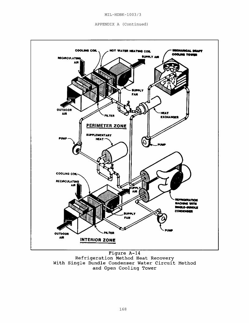
MIL-HDBK-1003/3
APPENDIX A (Continued)
168

MIL-HDBK-1003/3
APPENDIX A (Continued)
169

MIL-HDBK-1003/3
APPENDIX A (Continued)
Complete an economic evaluation for use of heatrecovery machines in large systems. If economically justified,the large system can be designed for multiple machineinstallations by using conventional machines in conjunction withheat recovery machines. The selection of a double tube bundlemachine is a design function where standby low-grade demandexists. Where this cannot be justified, use a single tube bundlemachine.
A-4.00 HVAC System Management. Cycling the boiler andrefrigeration chiller in a pattern responsive to the time of dayand prevailing weather conditions reduces energy consumption byreducing excess heating and cooling capacity during operatinghours. For large buildings, a computerized energy managementsystem may be justified. These systems can analyze weatherconditions, building and system characteristics, and HVACoperating conditions. Energy management systems then adjustvarious controls to provide optimum energy use.
170

MIL-HDBK-1003/3
APPENDIX BENGINEERED SMOKE CONTROL SYSTEMS
B1.00 Introduction. By the very nature of this type ofsystem; some of the requirements of NFPA 90A will need to bemodified or suspended. If air movement or pressures from theduct system are necessary to confine or control the flow ofsmoke, fans should not be shutdown or dampers closed.
B2.00 Specific Design Guidance
a) Suggested for use in large zones.
b) Smoke dampers should meet UL 555S, Standard forSafety Leakage Rated Dampers for Use in Smoke Control Systems. These are made in ratings of zero to four. Class 1 is a goodtight damper. Use Class 1 dampers where the return or exhaustair may meet the outside air to prevent contaminating the supplyair with smoke. Class 2 or Class 3 dampers (with more leakage)may otherwise be used for smoke zone dampers.
c) Return ducts used for smoke purging should be steelfabrication. Supply ducts should be insulated for protectionfrom fire outside the duct.
d) Fans used for smoke exhaust should be rated for 750degrees F continuous duty. Use an extended shaft and acommercially available propeller on the shaft to blow air ontothe motor. The air temperature in the fire room may reach 1,400degrees F, but this may be diluted with 70 degrees F air fromother rooms to permit use of an ordinary fan. Do not put themotor in the airstream and do not use an aluminum fan wheel. Donot stop the smoke exhaust fan during a fire.
e) Specify acceptance testing of the smoke controlsystems.
171

MIL-HDBK-1003/3
APPENDIX CDESIGN DO’s AND DON'Ts FOR VAV SYSTEMS
C-1.00 Introduction
C-1.01 Scope and Criteria. This appendix is intended for useby qualified engineers who are responsible for preparation andreview of plans and specifications for construction of VAV, HVAC,and dehumidifying systems. It complements the requirements ofNAVFACENGCOM and DOD manuals and instructions for theconstruction of HVAC systems. The designer is reminded thatnormal construction and maintenance problems encountered with alltypes of HVAC systems are not covered here, but should be fullyconsidered in the design.
C-1.02 Excellent Facilities. The objective of HVAC systemdesign is to provide excellent places to work and live for Navyand Marine Corps personnel. The goal is not only to minimize thelife cycle cost of the facilities, but also to maximize theperformance of the people who use the facilities. VAV systemsoffer enhanced comfort by allowing economical flexibility inzoning, better temperature control, better passive humiditycontrol at part load, and greater energy efficiency.
C-1.03 Importance of Design. Navy VAV systems often do notperform as the designer intends. An investigation of the causesof failure shows that considerable improvement in the success ofVAV can be achieved by special attention to good designpractices. This appendix is intended to provide feedback toalert the designer to recognize those areas where carefulattention can prevent deficiencies commonly found in Navy VAVsystems.
a) VAV systems incur problems for the same basicreasons that other types of air conditioning systems do. Theyare either improperly designed, constructed, or operated andmaintained.
b) Deficiencies in design often result from bothtechnical and practical aspects of the design. Improperpractical decisions often occur in the following areas: (1) lackof consideration of the constructability of the design,(2) failure to appreciate the importance of designing systemsthat can be operated and maintained, and (3) failure tocommunicate in sufficient detail the design intent and thusleaving too many decisions to the contractor.
c) Deficiencies in construction, inspection, andacceptance occur primarily in three areas: (1) the system may
172

MIL-HDBK-1003/3
APPENDIX C (Continued)
not be installed as designed, (2) the system is installed to meetrequirements of the design and submittals but quality ofworkmanship is such that the system will not function properly,and (3) although construction might be satisfactory in allrespects, acceptance testing is of poor quality and latentdefects in the systems go undetected.
d) Operation and maintenance deficiencies can occurfrom insufficient or improper training, the system receivinginadequate operating and maintenance attention, and the systemreceiving well meaning but misguided operation and maintenanceattention.
e) A failure in any of these areas can be fatal to thesuccessful operation of a VAV system.
C-1.04 System Simplicity. The most common fault of themajority of designs is that the systems are too complicated towork reliably. Some systems never work initially, others failbecause Naval operation and maintenance personnel do notunderstand them sufficiently to keep them working as designed. The chief area of concern is control systems. A designer isalways tempted to add features to improve performance andconserve energy but must weigh the potential benefits against theadditional cost and complexity. Feedback: On the average,systems have too many features and are too complex for the needsof the Navy. The designer should design systems that err towardsimplicity, at the expense of features, and require minimummaintenance.
C-1.05 Early Coordination. Having experienced numerousproblems on VAV systems, the Navy wishes to have a high level ofinteraction between the designer and the Engineer in Charge andwill often want to give the designer more direction than isnormal. To minimize design changes, it is important that therebe good communication. This is particularly true in the earlystages of the design. The designer shall communicate his designintent and the critical concepts of his proposed system,including simplicity in operation and maintenance, at the firstsubmittal opportunity. This will prevent the necessity ofchanging the concept of the design.
C-1.06 Dry Climates. Many Naval facilities are located inhumid climates and so there is a tendency to tailor designguidance for humid areas. There are also many Naval facilitieslocated in dry and cold climates. The practice associated withdesign in these facilities can be considerably different. The
173

MIL-HDBK-1003/3
APPENDIX C (Continued)
designer must be careful to fit his design to the area where heis working. Typical conditions in dry and cold climates arethat: the relative humidity is low; the daily dry bulb range ishigh; the outdoor air economizer is effective (at least for nightpurging); the sensible heat ratio is high and systems are oftendesigned primarily to handle the sensible load and to let theroom relative humidity float as it will. Naval facilitieslocated in dry and cold climates may require modifications to thecriteria listed below.
C-1.07 Selection of Type of Control System. Design controlsystems as simple as possible to provide adequate control andgive careful consideration to the following when selecting thetype of control system:
a) Pneumatic Controls. Pneumatic controls seldom workconsistently well in Naval facilities. Pneumatic controlsrequire frequent maintenance and calibration at a level that isnot usually performed by Naval personnel. Pneumatic systems areprone to fail from water or oil in the compressed air. Manypneumatic control systems are never set up properly by theinstalling contractor. Even hybrid control systems (e.g., DDCwith pneumatic actuators) can have similar problems because theelectric-to-pneumatic transducers have small passages that arevulnerable to moisture and oil in the compressed air. All otherthings being equal, pneumatic control is not a good choice forthe control system; but if operation and maintenance personnelare expert in pneumatic controls, have adequate funds formaintenance, and refuse to use state-of-art systems, pneumaticsystems may be justified.
b) Electric Control. For the sake of simplicity,electric VAV terminal unit controls may be used in conjunctionwith pressure dependent (PD) terminal units (refer topar. C-2.10). This type of zone temperature control requiresonly the simplest of control sequences and therefore, will beeasier for Naval operation and maintenance personnel tounderstand and maintain. Electric controls for the centralequipment (e.g., CHW valve and control, etc.) are in common useand are suitably rugged, however, may not be accurate enough forthe application.
c) Analog Electronic Control. If pressure independent(PI) terminal units are used, it will be necessary to haveelectronic controls. Analog electronics usually introduceadditional levels of complexity whose advantages can beoutweighed by the likelihood that they will not be understood by
174

MIL-HDBK-1003/3
APPENDIX C (Continued)
the operating and maintenance personnel. It is recommended thatelectronic controls be used with as simple a sequence aspossible.
d) DDC. DDC is the state-of-art of control systemsand is in common use throughout the industry. Navy DDC systemsare distributed (have controllers located near the equipmentbeing controlled) and usually include a means for the operator todiagnose HVAC operation from a remote location. A DDC system isthe system of choice for Naval projects if the facility operatingand maintenance personnel are qualified in DDC systems or, atleast, are willing to take the recommended training and make asincere effort to properly use DDC. The designer should notoverdesign the DDC system, should make it simple, and as userfriendly as possible. It is critical that quality DDC sensors beused which have long term (5 years) stability to minimizemaintenance and calibration while providing accurate conditions. DDC systems may incorporate energy management strategies inaddition to normal control functions with little or no additionalcost.
C-2.00 Do’s and Don'ts
C-2.01 Do not oversize the system. Do not add safety factorsin load calculations. The calculation methods already have anadequate safety factor included. Feedback: Many Navy VAVsystems are significantly oversized. This not only costs more,but it handicaps the system in performing the already difficulttask of providing comfort under difficult part load conditionscommonly seen in humid, coastal environments where many Navyinstallations are located. Because of the inherent diversityfactor in VAV systems, they are more "forgiving" of capacityshortages than are constant volume systems.
C-2.02 Use computerized load calculations based on the ASHRAEtransfer function method. The manual use of the total equivalenttemperature difference/time averaging (TETD/TA) method or thecooling load temperature difference/cooling load factor(CLTD/CLF) methods are not as accurate and require engineeringjudgment which typically leads to unnecessary conservatism.
C-2.03 Design for diversity. Select central air handlingequipment and heating/refrigeration systems for "block" loads. Spread diversity appropriately through the supply ducts, takingfull diversity at the air handling unit, and lessening diversity
175

MIL-HDBK-1003/3
APPENDIX C (Continued)
when moving away from the air handling unit toward the VAVterminal units, until no diversity is taken at the distant VAVterminal runouts.
C-2.04 Design and specify for both peak and part loadconditions. Submit design calculations verifying that carefulconsideration has been given to the following areas:
a) Consider the psychrometric performance of thecooling coil (taking into account the method of capacity control)during difficult off peak conditions when the room sensible heatratio can be significantly reduced. Select appropriatelydifficult off peak conditions for analysis. At a minimum, showhow the system will perform when sensible load due to solar islost while latent loads remain constant. This is not necessaryin dry climates. The VAV system may operate with 100 percentoutside air during warm-up or on maximum heating days.
b) When selecting a fan for a VAV system, submitdesign calculations verifying the system has been analyzed at thefollowing three points: (1) normal peak load (includingdiversity), (2) maximum cooling load (no diversity with VAV boxdampers open), and (3) minimum cooling load (with VAV boxes atthe minimum flow condition). The supply fan should bescheduled/specified (cfm and pressure) to satisfactorily meet allthree of these operating points. Submit design calculations anda typical fan performance curve showing all of these pointsplotted. A fan should never be selected which will becomeunstable or overload anywhere on its operating curve.
c) Consider limiting the size of VAV air handlingunits to 10,000 cfm for flexibility and ease of maintenance. Plan for units to serve zones with different exposures to achieveunit diversity.
d) VAV terminal boxes should be sized with bothmaximum and minimum flows in mind. Schedules should indicatecfm, neck velocity, pressure drop, and noise criteria at bothmaximum and minimum flow (refer to par. C-2.11).
e) For air distribution devices, the minimum allowable"throw" should be scheduled for both maximum and minimum flowconditions.
f) If an outside air injection fan is used to maintainminimum ventilation, select a fan with a "steep" fan curve whichwill maintain a relatively constant flow regardless of mixing box
176

MIL-HDBK-1003/3
APPENDIX C (Continued)
pressure. This analysis will be similar to that used forspecifying the supply fan. Knowing the range of total staticpressure expected in normal operation of the supply fan, estimatethe expected range of mixing box pressures. Select the fan todeliver design minimum ventilation at an average system operatingpoint (typically less than design peak). With this method ofselection, the fan will deliver slightly more than design underpeak flow conditions and slightly less than design under minimumflow conditions. The fan should be scheduled/specified tosatisfactorily meet flow requirements at each of these threeoperating points.
g) Submit detailed computerized design calculations(this is mandated by the static regain method for sizing) whichindicate the amount of diversity used for sizing ductwork andwhere the diversity was applied.
h) It is recommended that the system be designed for 8to 12 air changes per hour with a minimum supply airflow of 4 airchanges per hour.
C-2.05 Design supply ductwork using the static regain method. This will require computerized ductwork design analysis. Designreturn ductwork using the equal friction method. The staticregain method keeps the static pressure in the supply system morenearly constant throughout. This enhances the inherent controlstability of the system. It also greatly assists in naturallybalancing airflow through the system minimizing any advantage forusing PI terminal boxes. Using the static regain method requiresthat more attention be given to the design of the duct system butthis is effort well spent.
C-2.06 To control humidity and for simplicity, design for aconstant cooling supply air temperature. The leaving airtemperature should be controlled using a chilled water valvemodulated to maintain supply air temperature as sensed by aleaving air sensor. Resetting the supply air temperature upwardsincreases the sensible heat ratio of the coil and leads to highspace relative humidity and poor indoor air quality. Thepotential to save refrigeration energy by raising the coolingsupply air temperature is more than offset by the increased fanenergy needed to move more air. In addition, changes in supplyair temperature can lead to condensation on and around diffusers. Exception: There are cases where, to prevent overcooling atminimum flow or to minimize reheating, resetting the cooling
177

MIL-HDBK-1003/3
APPENDIX C (Continued)
supply air temperature might be appropriate. Also there arecases in dry climates where it would be permissible to varysupply air temperature.
C-2.07 Do not use a return air fan in a VAV system. Measuringand control requirements for tracking the return air fan with thesupply air fan are too demanding to work in a Naval VAV system. In most cases a return fan is unnecessary to return air to theHVAC unit. In cases where the pressure drop in the return ductexceeds the drop for outdoor air, the mixing box may be at alower suction pressure. Select outside air and return damperswith this in mind.
C-2.08 Economizers should be used when significant benefitscan be shown. (Clearly dry or cold climates are cases whereeconomizers can be effective.) Feedback: Economizers in NavyVAV systems fail in a majority of cases due to complexarrangements. Keep economizer systems simple and use onlyoutdoor air dry bulb sensors for changeover. The economizingfeature can save a lot of energy in many applications but thedesigner must confer with the appropriate NAVFACENGCOM EFD or EFAwhen using this design.
a) Economizers should have outdoor air dry bulb typechangeover instead of outdoor air versus return air comparatorsor enthalpy type changeovers.
b) Economizers should only be used when the system canbe designed with gravity relief. Return or relief fans shouldnot be used.
C-2.09 Maintaining Ventilation Air. In most systems there arecircumstances under which satisfying the cooling load will notadequately ventilate the space. Unless it can be shown that thisis not the case, the designer shall design a positive means ofmaintaining ventilation rates during minimum flow conditions, tomaintain IAQ. Select minimum positions of VAV terminal units tomeet this requirement. Note: It is impossible with a VAV systemto absolutely maintain a minimum ventilation airflow to anyspace. The best that can be done is to maintain a constantventilation airflow on a per air handling unit basis andrecognize that ventilation will be improved in any zone that isshorted by mixing between rooms (especially in zones wherefan-powered boxes are used) and shorted rooms tend to be thosewhere people and lights are not present, and thus the ventilationrequirements are lower anyway. Use ASHRAE Standard 62 tomaximize IAQ.
178
MIL-HDBK-1003/3
APPENDIX C (Continued)
To maintain a constant outside air quantity being drawnin and supplied by the AHU, a separate outside air injection fanor PI VAV box should be used. Use of an injection fan isencouraged rather than a PI VAV box because it is a more reliablemethod of providing constant ventilation from a simplicity andmaintainability viewpoint. The designer should be aware that PIunits rarely work properly in Navy installations because ofmaintenance problems with PI velocity sensing hardware/controls.Properly working PI units, however, would be a more accuratemeans of providing a constant flow throughout a given range ofmixing box pressures. A PI unit should be considered if therange of mixing box pressures expected is such that it would bedifficult to specify a fan which would deliver acceptable flowsthroughout the range of pressure.
C-2.10 Pressure Dependent (PD) Boxes. The use of PD VAV boxesrather than PI boxes is recommended. Feedback: PI velocityresetting controls are often a significant contributor to failureof Navy VAV systems. When determining the type of VAV terminalunits to use in a system, give careful consideration of thefollowing feedbacks:
a) The most important feature touted for PI units isthat they respond to fluctuations in system pressure and thusenhance control stability by reducing "hunting." However, whenthe supply duct system has been properly designed for staticregain, there is no clear evidence that the use of PI unitsresults in greater zone temperature control stability than whenusing PD units. The transfer functions and time constants in atypical VAV unit control are such that the potential benefits ofvelocity resetting are nullified by the disadvantages of theadditional and complicated control loop.
b) PI controls claim to render the whole systemvirtually self-balancing. However, in a system with PD controlsand a well designed static regain duct system, the VAV dampersrespond to changes in load sensed by the thermostat and respondto balance the air in a similar way.
c) Maximum and minimum airflow limiting is a featurethat is inherent with PI control units. However, there is somequestion as to how well the velocity sensors used for thispurpose actually measure flow (setpoints are at the extreme lowend of their range). Some manufacturers say the velocity loopreadily drifts out of calibration and must be auto-calibratedregularly by using a DDC system. The problem is worse at lowerairflow. A differential pressure flow ring or flow cross is
179

MIL-HDBK-1003/3
APPENDIX C (Continued)
accurate only down to about 400 fpm (which unfortunately might beas high as 33 to 50 percent of maximum flow in many cases). Since desired minimum flow will usually be less than this, thedifferential pressure PI is not accurate for controlling minimumflow. The other common method uses a hot wire anemometer orsimilar device for sensing. This is not very good because thesensor is a single point in the inlet duct rather than amulti-point device (as used by the flow ring described above). It would only be accurate for a box that had many diameters ofstraight duct upstream (not the usual case). In addition, theresponse time is too slow for good PI control.
d) Minimum flow can be set on PD units by installingmechanical stops, by setting the actuator stroke through linkageadjustments, or by other similar means. These arestraightforward testing and balancing procedures.
e) PI costs somewhat more than PD on the average, ismuch more complicated for maintenance personnel, and theadditional control components are more prone to failure.
f) If PI is used, however, the designer must becareful to specify that supply maximums and minimums are checkedafter the equipment is installed. Factory adjustments haveproven to not be an adequate guarantee that the installedequipment will function as needed.
C-2.11 Carefully consider the throttling characteristics whenselecting the type and size of VAV terminal units. The installedcharacteristic curve of a throttling damper expected to modulatesupply air to a space, is a function of the inherent characteristic curve of the device and the ratio of the systempressure drop to the drop across the damper at maximum flow. Asthe pressure drop of the damper at maximum flow is reduced (byselecting larger and larger dampers for a given flow rate--apractice promoted by the desire to save fan energy), theinstalled characteristic tends to move across the spectrum towardquick opening characteristics. The geometry of butterfly damperstends to exaggerate this shift. With dampers specially designedto retain linearity, this shift can be greatly reduced.
a) A shift toward quick opening increases the gain ofthe control component, i.e., a smaller part of its stroke isactually used for control. This is detrimental to the stabilityof the control system. The common tendency of selecting damperswith very low pressure drops can result in control that is nearly
180

MIL-HDBK-1003/3
APPENDIX C (Continued)
"two-position." It is better to pay some fan energy penalty andhave a system that provides more stable control. Properly sizedcontrol dampers will be smaller than fan casings and have greatermaximum flow pressure drops than those usually used.
b) If PI terminal units are used, sizing becomes evenmore critical. Oversizing the boxes to reduce maximum flowpressure drop results in low neck velocities, which in turncreate problems for PI flow measuring devices. To minimizeproblems with sensing minimum flows in PI VAV boxes, size the boxsuch that at minimum flow, the neck velocity will be at least 500fpm.
C-2.12 Give special attention to linkages (VAV terminal unitdamper, fan inlet guide vanes, and controllable pitch vanes). Feedback: Problems due to poorly designed/constructed linkagesare very common in Naval VAV systems. Either specificallydescribe linkage requirements (because manufacturers are sodifferent, this may be difficult for VAV terminal units) or atleast require detailed shop drawings of linkages and pay closeattention to them. Finally, linkages should be included in thespecifications as a specific item to be performance checkedduring the acceptance testing of the system.
C-2.13 Pay close attention to Contractor's responsibility ofcoordinating which of his subcontractors provides VAV terminalunits/controls/actuators. Feedback: Contractors' lack ofcoordination of the VAV terminal unit and controls often leads toproblems which go undetected. Even though DOD specificationpolicy recognizes only the Contractor as the single entity, andnot the subcontractors (thus not stating who does what), carefulattention to submittals in this area will avoid many problems. To help with this, the VAV boxes, thermostats, and associatedequipment should be specified as a system and the Contractor berequired to make his submittal for all items at the same time.
C-2.14 Whichever of the available methods of selecting supplyair outlets is used, consider the full range of flow ratesexpected. Recognize the effects of room geometry on satisfactoryperformance (e.g., the Coanda effect depends upon having a flatceiling, without interruptions, etc.).
a) It is recommended that VAV supply diffusers be ofthe linear slot type capable of supplying air horizontally alongthe ceiling utilizing the Coanda effect to provide good airdistribution. In cooling only applications, the diffusers shouldbe located centrally in the space and blow in all directions. In
181

MIL-HDBK-1003/3
APPENDIX C (Continued)
exterior spaces with fan-powered boxes, the location depends onthe magnitude of the heating load. If the heating load is lessthan 250 Btuh per linear foot of exterior wall (includinginfiltration), the diffuser should again be located centrally andblow in all directions. If the heating load is between 250 and400 Btuh per linear foot of exterior wall, the diffuser should belocated near and parallel to the exterior wall and blowhorizontally back into the room.
b) Diffusers which have operable internal dampers forvarying airflow should not be used in lieu of conventionalduct-mounted terminal units in a VAV system design.
C-2.15 Locate the static pressure sensor, for modulating fancapacity, out in the supply duct system, not at the fandischarge. Expect some field adjustment to be required to findthe best location. In many systems, the first location istwo-thirds the distance from the supply fan to the end of themain trunk duct. Sensors shall have proper static sensingelements.
Provide protection against overpressurization of thesupply duct. This should be accomplished by a high limit ductstatic pressure sensor located at the fan discharge. This sensorshould turn off the supply fan if the duct static pressure risesabove setpoint and require manual reset of the supply fan.
C-2.16 Balancing dampers should not be necessary for VAVsystems. If the supply ductwork is designed properly using thestatic regain method (refer to par. C-2.05) and VAV terminalunits are properly sized/selected (refer to par. C-2.11) and setup properly during commissioning, the system should besufficiently self-balancing.
C-2.17 Use round ducts wherever space availability permits. Round ducts are acoustically superior to rectangular ducts andnormally cost less. In high velocity systems, the additionalfriction losses of duct walls and balancing dampers ofrectangular ducts cause the system to be inherently less stable. Round ducts also produce less noise than rectangular ducts.
C-2.18 To save construction expense, it is now common to serveceiling outlets with short runs of flexible duct. Limit thelength of flexible duct and avoid bends to minimize duct frictiondrop. Figure these pressure drops, and do not show longer runs
182

MIL-HDBK-1003/3
APPENDIX C (Continued)
on the drawings than you allow in the specifications. Seekself-balancing by having equal lengths of flexible ducts insteadof long and short runs on the same system.
When designing VAV systems, do not use flex ductupstream of the terminal VAV box (i.e., between the air handlingunit and the VAV box). Use flex duct only to make terminal runsto diffuser boots and limit applications to straight runs of nomore than 5 feet. Hard duct 90 degree elbows should be used toconnect the flex duct to the diffuser boot. Do not use flex ductfor elbows.
C-2.19 Many zones in Navy buildings do not need heating. These include zones in a building in a cooling only climate or completely interior zones in any climate. In these situations, arecommended control sequence is as follows: the air handling unitsupplies a constant cold temperature (say 55 degrees F) air. Each VAV box modulates from maximum position (fully open) tominimum position (fully closed) through the control range of theroom thermostat. The justification for allowing full close-offin interior zones, in light of IAQ concerns, is that the peopleload plus lights in an interior zone are substantial, usuallyamounting to 50 percent of the zone load or more. This is truefor perimeter zones in a cooling only climate also, but to alesser extent. So, if people are present, and thus the lightsare on, the load will be above the minimum anyway. Therefore,the minimum is not needed. If the people are gone and the lightsare out, the load may fall below where a ventilation determinedlimit would come into play, but since the people are gone, noventilation is needed.
C-2.20 For zones that need heating, there are two recommendedsituations. For the very cold climate when the peak heating loadon the exterior wall is greater than 400 Btuh per linear foot ofwall (including infiltration), a separate skin heating system maybe used consisting of baseboard hot water convectors. Two-position electric spring-return control valves should beinstalled in each zone. Thus each perimeter zone will be servedby a VAV terminal unit for cooling and a corresponding section ofhot water convector for heating. The zone thermostat shouldcontrol both the VAV damper actuator and hot water valve actuatorin sequence at the cooling and heating setpoint. The VAV dampershould have a mechanical minimum position for ventilation airwhich would be field set during the testing and balancing phaseof installation.
183

MIL-HDBK-1003/3
APPENDIX C (Continued)
a) For a mild or moderate heating situation when thepeak heating load on the exterior wall is less than 400 Btuh perlinear foot of wall, the following arrangement is recommended. Each zone should be served by the series fan-powered VAV box witha hot water heating coil and overhead supply diffusers. Thethermostat should modulate the VAV damper closed to themechanically field set minimum position at the cooling setpoint. On the further drop in space temperature to the heating setpoint,the hot water valve should open (using a modulating electricspring-return actuator) to allow control of heating. Analternate arrangement uses a parallel fan-powered VAV box withheating coil. The VAV box fan motor should be started when theVAV damper closes to a supply rate of 4 air changes per hour.
b) Since the use of fan-powered boxes adds severalhundred dollars per zone of first cost, the zoned baseboard heatoption (described for very cold climates) may be considered, evenin mild climates.
c) In perimeter zones there will be a need to setbackthe temperature in many buildings when there is no occupancy. This is generally accomplished by a night setback thermostatwhich can bring the heating system back on line to maintain thesetback temperature.
C-2.21 In perimeter zones with a VAV cooling system and aseparate perimeter heating system, design controls so thatoccupants cannot adjust thermostats for simultaneous heating andcooling. This can be done by using a thermostat with cooling andheating setpoints integrated so that ranges of possibleadjustment do not overlap.
C-2.22 Systems that are to be shut down or setback duringunoccupied periods can present special problems. The greatestload will occur during start-up. The supply air or coil shall becapable of bringing the temperature back to design in areasonable time without ill effects. For instance, the designermust be careful that the temperature of supply air duringstart-up is not too far below the room dew point temperature toprevent condensation on diffusers.
Specify a method for building warm-up after setback. Many systems contain totally interior zones that have beendesigned without heat. The space, after setback over a weekend,can require an unacceptably long period of time to come up totemperature. This warm-up sequence could be accomplished byusing a microprocessor-based thermostat with a built-in automatic
184

MIL-HDBK-1003/3
APPENDIX C (Continued)
changeover. The warm-up cycle would be as follows: in themorning the air handling unit is turned on (typically by the samedevice that turned the unit off for setback). A central hotwater coil in the AHU is activated, and the thermostats aresignaled to warm-up action. During the warm-up the interior zonethermostats thus open up the air dampers to warm up the space tothe thermostat setpoint. After the warm-up period, thethermostats are signaled to return to normal action for coolingand the AHU hot water coil is deactivated.
C-2.23 The designer should be aware that pneumatic damperactuators provided are often inadequately sized and are notcapable of performing their specified duty. Paying specialattention to submittals in this area or specifying pilotpositioners could help avoid many problems.
C-2.24 Note that use of air troffer lighting return may reducedesign air volume to an undesirable low air distribution level(in non-fan-powered systems).
C-2.25 Modulate the capacity of the supply fan, givingattention to the method chosen. Be aware that all of theavailable methods, including variable speed, inlet guide vanes,controllable pitch vane axial, and even discharge dampers, haveproblems in Navy VAV systems. Feedback: Inlet guide vanes areoften found to be inoperable due to poor maintenance. They arenot the trouble-free devices that the designers think they are.It is recommended that supply air fans under 10 horsepower beforward curved fans with inlet guide vanes. Supply fans largerthan 10 horsepower should be equipped with a variable frequencydrive (VFD). When designing a system with a VFD, the followingguides may be of help.
C-3.00 Sequence of Operation. For suggested sequence ofoperations, refer to par. 8.5.
C-4.00 System Commissioning. For recommended commissioningprocedures, refer to pars. 8.6 and 8.6.7 which specificallyaddress VAV systems.
C-4.01 Operation and Maintenance Personnel Training. It issuggested that training sessions of operation and maintenance
185

MIL-HDBK-1003/3
APPENDIX DVARIABLE SPEED DRIVES (VFD)
D-1.00 Introduction
D-1.01 Scope and Criteria. This appendix is intended toprovide basic information on the principles of operation ofVFD’s, description of different types of VFD’s, guidance on theproper application of VFD’s, and installation guidelines toensure successful operation of VFD’s. Over the last few years,the VFD has become one of the most effective motor controllersavailable for varying the speed of squirrel-cage inductionmotors. VFD’s save energy, reduce electrical consumption,enhance equipment performance, are highly reliable, and havebecome affordable. Much of the material presented in thisAppendix was developed by Mr. Solomon S. Turkel, SeniorInstructor and Course Author for Advanced Technologies Marketingand Service (ATMS) Inc., Baltimore, MD.
D-1.02 Terminology. VFD’s drives are sometimes calledadjustable frequency controllers (AFC’s). It is incorrect tocall them inverters or even adjustable speed drives (ASD’s). Theterm "ASD" refers to many types of adjustable speed drives,including belt or gear drives, eddy-current clutches, variable-pitch sheave drives, and DC systems, as well as VFD’s. The VFDis the only type of motor drive that controls the speed of an ACinduction motor by changing the frequency and voltageappropriately. The VFD microprocessor-based motor controllerincorporates an electronic control section, an electromagneticand semiconductor power section, and typical components used withstandard motor controllers. Currently, available sizes rangefrom 1/3 horsepower (hp) to thousands of hp.
D-1.03 Operation. The principles of operation of VFD’s areclosely related to basic motor theory. During operation, thestator’s rotating magnetic field, which is created by the AC linepower to the motor, induces a voltage in the rotor. This inducedvoltage causes a current to flow in the rotor, which createsmagnetic fields with north and south poles. The synchronousspeed of an AC induction motor is dependent upon the number ofpoles in the stator and the frequency of the line power applied. The basic equation is as follows:
Speed = (120 times frequency) divided by number of poles
From this equation , a four-pole motor operating at 60Hz will have synchronous speed of 1800 rpm. When a VFD suppliespower to an AC motor, it has the capability to provide a voltage
186

MIL-HDBK-1003/3
APPENDIX D (Continued)
at a frequency from less than 1 Hz to about 120 Hz. This meansthat the motor may run extremely slow or very fast, depending onthe frequency supplied; and the amplitude of the voltage suppliedmust be proportional to the frequency to ensure the propervolts/hertz ratio for the specific motor. The output torque fora motor is determined by the ratio of voltage applied to themotor at a given frequency. Failure to maintain the propervolts-per-hertz ratio will affect motor torque, temperature,speed, noise, and current draw. Thus, for a motor to produce itsrated torque at variable speeds, it is also necessary to controlthe voltage as well as the frequency supplied to the motor. Forexample, a 460 volt motor operating at 60 Hz will have avolts/hertz ratio of 7.67 to 1. For a VFD to operate this motorat 30 Hz (half speed), the motor voltage must be reduced to 230volts to maintain the same torque characteristics for the motor. Motors are designed with specific torque characteristics and areclassified accordingly. While two motors may have the samehorsepower rating, their actual torque capability in the areas ofbreakaway torque, pull-up torque, peak torque, and full-loadtorque may be different, depending on their NEMA classifications. Typical designs are Type A, B, C, and D. Refer to NationalElectrical Manufacturers Association (NEMA) MG-1, Motors andGenerators, for a detailed explanation of these NEMA designs andof motor torque capabilities. Although the motor is sized byhorsepower, the required torque at all speeds is the key tosuccessful, efficient operation of the VFD and its motor.
D-1.04 Types of VFD’s. Although VFD’s control the speed of anAC induction motor by varying the motor’s supplied voltage andfrequency of power, they do not all use the same designs in doingso. The major VFD designs commonly used at the time ofpublication of this handbook are:
a) Pulse Width Modulated (PWM)
b) Current Source Inverter (CSI)
c) Voltage Source Inverter (VSI)
d) Flux Vector Drive
An understanding of these different designs, along with theiradvantages and disadvantages will be beneficial to correctlymatch the VFD with the motor in a specific application.
187

MIL-HDBK-1003/3
APPENDIX D (Continued)
D-1.04.1 PWM Design
a) The PWM drive has become the most commonly useddrive controller because it works well with motors ranging insize from about 1/2 hp to 500 hp. A significant reason for itspopularity is that it’s highly reliable, affordable, and reflectsthe least amount of harmonics back into its power source. Mostunits are rated either 230 volts or 460 volts, three-phase, andprovide output frequencies from about 2 Hz to 400 Hz. Nearly 100manufacturers market the PWM controller.
b) In the PWM drive, an AC line supply voltage isbrought into the input section. From here, the AC voltage passesinto a converter section that uses a diode bridge converter andlarge DC capacitors to create and maintain a stable, fixed DC busvoltage. The DC voltage passes into the inverter section usuallyfurnished with insulated gate bipolar transistors (IGBT’s), whichregulate both voltage and frequency to the motor to produce anear sine wave like output.
c) The term "pulse width modulation" explains how eachtransition of the alternating voltage output is actually a seriesof short pulses of varying widths. By varying the width of thepulses in each half cycle, the average power produced has a sine-like output. The number of transitions from positive to negativeper second determines the actual frequency to the motor.
d) Switching speeds of the IGBT’s in a PWM drive canrange from 2 kHz to 15 kHz. Today’s newer PWM designs use powerIGBT’s, which operate at these higher frequencies. By havingmore pulses in every half cycle, the motor whine associated withVFD applications is reduced because the motor windings are nowoscillating at a frequency beyond the spectrum of human hearing. Also, the current wave shape to the motor is smoothed out ascurrent spikes are removed.
e) PWM’s have the following advantages:
(1) Excellent input power factor due to fixedDC bus voltage.
(2) No motor cogging normally found withsix-step inverters.
(3) Highest efficiencies: 92 percent to96 percent.
188

APPENDIX D (Continued)
(4) Compatibility with multimotor applications.
(5) Ability to ride through a 3 to 5 Hz power loss.
(6) Lower initial cost.
f) The following disadvantages, however, should alsobe considered:
(1) Motor heating and insulation breakdown in someapplications due to high frequency switching of transistors.
(2) Non-regenerative operation.
(3) Line-side power harmonics (depending on theapplication and size of the drive).
D-1.04.2 CSI Design. In the CSI drive design, the incomingpower source is converted to DC voltage in an SCR convertersection, which regulates the incoming power and produces avariable DC bus voltage. This voltage is regulated by the firingof the SCR’s as needed to maintain the proper volt/hertz ratio. SCR’s are also used in the inverter section to produce thevariabe frequency output to the motor. CSI drives are inherentlycurrent regulating and require a large internal inductor tooperate, as well as a motor load.
a) CSI’s have the following advantages:
(1) Reliability due to inherent current limitingoperation.
(2) Regenerative power capability.
(3) Simple circuitry.
b) The following are disadvantages which should beconsidered in the use of CSI technology:
(1) Large power harmonic generation back into thepower source.
(2) Cogging below 6 Hz due to square wave output.
(3) Use of large and costly inductor.
189

MIL-HDBK-1003/3
APPENDIX D (Continued)
(4) High voltage spikes to motor windings.
(5) Load dependent; poor for multimotorapplications.
(6) Poor input power factor due to SCR convertersection.
D-1.04.3 VSI Design. The VSI drive is very similar to a CSIdrive in that it also uses an SCR converter section to regulateDC bus voltage. Its inverter section produces a six-step output,but is not a current regulator like the CSI drive. This drive isconsidered a voltage regulator and uses transistors, SCR’s, orgate turn off thyristors (GTO’s) to generate an adjustablefrequency output to the motor.
a) VSI’s have the following advantages:
(1) Basic simplicity in design.
(2) Applicable to multimotor operations.
(3) Operation not load dependent.
b) As with other types of drives, there aredisadvantages:
(1) Large power harmonic generation back into thepower source.
(2) Poor input power factor due to SCR convertersection.
(3) Cogging below 6 Hz due to square wave output.
(4) Non-regenerative operation.
D-1.04-4 Flux Vector PWM Drives
a) PWM drive technology is still considered new and iscontinuously being refined with new power switching devices andsmart 32-bit microprocessors. AC drives have always been limitedto normal torque applications while high torque, low rpmapplications have been the domain of DC drives. This has changedrecently with the introduction of a new breed of PWM drive, theflux vector drive.
190

MIL-HDBK-1003/3
APPENDIX D (Continued)
b) Flux vector drives use a method of controllingtorque similar to that of DC drive systems, including wide speedcontrol range with quick response. Flux vector drives have thesame power section as PWM drives, but use a sophisticated closedloop control from the motor to the drive’s microprocessor. Themotor’s rotor position and speed is monitored in real time via aresolver or digital encoder to determine and control the motor’sactual speed, torque, and power produced.
c) By controlling the inverter section in response toactual load conditions at the motor in a real time mode, superiortorque control can be obtained. The personality of the motormust be programmed into or learned by the drive in order for itto run the vector control algorithms. In most cases, specialmotors are required due to the torque demands expected of themotor.
d) The following are advantages of this new drivetechnology:
(1) Excellent control of motor speed, torque, andpower.
(2) Quick response to changes in load, speed, andtorque commands.
(3) Ability to provide 100 percent rated torque atzero speed.
(4) Lower maintenance cost as compared to DCmotors and drives.
e) The following are disadvantages:
(1) Higher initial cost as compared to standardPWM drives.
(2) Requires special motor in most cases.
(3) Drive setup parameters are complex.
While flux vector technology offers superior performance forcertain special applications, it would be considered "overkill"for most applications well served by standard PWM drives.
D-1.05 Application of VFD’s to Specific Loads. VFD’s are themost effective energy savers in pump and fan applications, and
191

MIL-HDBK-1003/3
APPENDIX D (Continued)
they enhance process operations, particularly where flow controlis involved. VFD’s soft start capabilities decrease electricalstresses and line voltage sags associated with full voltage motorstart-ups, especially when driving high-enertia loads. For themotor to produce the required torque for the load, the VFD musthave ample current capability to drive the motor. It isimportant to note that machine torque is independent of motorspeed and that load horsepower increases linearly with rpm. Individual load types are as follows:
a) Constant torque loads. Constant torque loadsrepresent 90 percent of general industrial machines (other thanpumps and fans). Examples of these load types include generalmachinery, hoists, conveyors, printing presses, positivedisplacement pumps, some mixers and extruders, reciprocatingcompressors, as well as rotary compressors.
b) Constant horsepower loads. Constant horsepowerloads are most often found in the machine tool industry andcenter driven winder applications. Examples of constanthorsepower loads include winders, core-driven reels, wheelgrinders, large driller machines, lathes, planers, boringmachines, and core extruders.
Traditionally, these loads were considered DC driveapplications only. With high performance flux vector VFD’s nowavailable, many DC drive applications of this type can be nowhandled by VFD’s.
c) Variable torque loads. Variable torque loads aremost often found in variable flow applications, such as fans andpumps. Examples of applications include fans, centrifugalblowers, centrifugal pumps, propeller pumps, turbine pumps,agitators, and axial compressors. VFD’s offer the greatestopportunity for energy savings when driving these loads becausehorsepower varies as the cube of speed and torque varies assquare of speed for these loads. For example, if the motor speedis reduced 20 percent, motor horsepower is reduced by a cubicrelationship (.8 x .8 x .8), or 51 percent. As such, utilitiesoften offer subsidies to customers investing in VFD technologyfor their applications. Many VFD manufacturers have freesoftware programs available for customers to calculate anddocument potential energy savings by using VFD’s.
D-1.06 Special Applications of VFD’s. If any of the followingoperations apply, use extra care in selecting a VFD and its setupparameters.
192

MIL-HDBK-1003/3
APPENDIX D (Continued)
a) VFD operating more than one motor. The total peakcurrents of motor loads under worst operating conditions must becalculated. The VFD must be sized based on this maximum currentrequirement. Additionally, individual motor protection must beprovided here for each motor.
b) Load is spinning or coasting when the VFD isstarted. This is very often the case with fan applications. When a VFD is first started, it begins to operate at a lowfrequency and voltage and gradually ramps up to a preset speed. If the load is already in motion, it will be out of sync with theVFD. The VFD will attempt to pull the motor down to the lowerfrequency, which may require high current levels, usually causingan overcurrent trip. Because of this, VFD manufacturers offerdrives with an option for synchronization with a spinning load;this VFD ramps at a different frequency.
c) Power supply source is switched while the VFD isrunning. This occurs in many buildings, such as hospitals, whereloads are switched to standby generators in the event of a poweroutage. Some drives will ride through a brief power outage whileothers may not. If your application is of this type, it must bereviewed with the drive manufacturer for a final determination ofdrive capability.
d) Hard to start load. These are the motors that dimthe lights in the building when you hit the start button.
Remember, the VFD is limited in the amount ofovercurrent it can produce for a given period of time. Theseapplications may require oversizing of the VFD for higher currentdemands.
e) Critical starting or stopping times. Someapplications may require quick starting or emergency stopping ofthe load. In either case, high currents will be required of thedrive. Again, oversizing of the VFD may be required.
f) External motor disconnects required between themotor and the VFD. Service disconnects at motor loads are veryoften used for maintenance purposes. Normally, removing a loadfrom a VFD while operating does not pose a problem for the VFD. On the other hand, introducing a load to a VFD by closing a motordisconnect while the VFD is operational can be fatal to the VFD. When a motor is started at full voltage, as would happen in thiscase, high currents are generated, usually about six times thefull load amperes of the motor current. The VFD would see these
193

MIL-HDBK-1003/3
APPENDIX D (Continued)
high currents as being well beyond its capabilities and would gointo a protective trip or fail altogether. A simple solution forthis condition is to interlock the VFD run permissive circuitwith the service disconnects via an auxiliary contact at theservice disconnect. When the disconnect is closed, a permissiverun signal restarts the VFD at low voltage and frequency.
g) Power factor correction capacitors being switchedor existing on the intended motor loads. Switching of powerfactor capacitors usually generates power disturbances in thedistribution system. Many VFD’s can and will be affected bythis. Isolation transformers or line reactors may be requiredfor these applications.
Power factor correction at VFD-powered motor loadsis not necessary as the VFD itself does this by using DCinternally and then inverting it into an AC output to the motor. VFD manufacturers warn against installing capacitors at the VFDoutput.
D-1.07 Sizing VFD’s for the Load. To properly size a VFD foran application, you must understand the requirements of the load. The torque ratings are as important as the horsepower ratings. Every load has distinct torque requirements that vary with theload’s operation; these torques must be supplied by the motor viathe VFD. You must have a clear understanding of these torques.
a) Breakaway torque: torque required to start a loadin motion (typically greater than the torque required to maintainmotion).
b) Accelerating torque: torque required to bring theload to operating speed within a given time.
c) Running torque: torque required to keep the loadmoving at all speeds.
d) Peak torque: occasional peak torque required bythe load, such as a load being dropped on a conveyor.
e) Holding torque: torque required by the motor whenoperating as a brake, such as down hill loads and high inertiamachines.
D-1.08 Guidelines for Matching VFD to Motor. The followingguidelines will help ensure a correct match of VFD and motor:
194

MIL-HDBK-1003/3
APPENDIX D (Continued)
a) Define the operating profile of the load to whichthe VFD is to be applied. Include any or all of the torqueslisted in par. D-1.07. Using a recording true rms ammeter torecord the motor’s current draw under all operating conditionswill help in doing this. Obtain the highest "peak" currentreadings under the worst conditions. Also, see if the motor hasbeen working in an overloaded condition by checking the motorfull-load amperes (FLA). An overloaded motor operating atreduced speeds may not survive the increased temperatures as aresult of the reduced cooling effects of the motor at these lowerspeeds.
b) Determine why the load operation needs to bechanged. Very often VFD’s have been applied to applicationswhere all that was required was a "soft start" reduced voltagecontroller. The need for the VFD should be based on the abilityto change the load’s speed as required. In those applicationswhere only one speed change is required, a VFD may not benecessary or practical.
c) Size the VFD to the motor based on the maximumcurrent requirements under peak torque demands. Do not size theVFD based on horsepower ratings. Many applications have failedbecause of this. Remember, the maximum demands placed on themotor by the load must also be met by the VFD.
d) Evaluate the possibility of required oversizing ofthe VFD. Be aware that motor performance (breakaway torque, forexample) is based upon the capability of the VFD used and theamount of current it can produce. Depending on the type of loadand duty cycle expected, oversizing of the VFD may be required.
D-1.09 Key VFD Specification Parameters. The most importantinformation to be included in a VFD specification are continuouscurrent rating, overload current rating, and line voltage ofoperation.
a) Continuous run current rating. This is the maximumrms current the VFD can safely handle under all operatingconditions at a fixed ambient temperature (usually 40 degrees C). Motor full load sine wave currents must be equal to or less thanthis rating.
b) Overload current rating. This is an inversetime/current rating that is the maximum current the VFD canproduce for a given time frame. Typical ratings are 110 percentto 150 percent overcurrent for 1 minute, depending on the
195
MIL-HDBK-1003/3
APPENDIX D (Continued)
manufacturer. Higher current ratings can be obtained byoversizing the VFD. This rating is very important when sizingthe VFD for the currents needed by the motor for breakawaytorque.
c) Line voltage. As with any motor controller, anoperating voltage must be specified. VFD’s are designed tooperate at some nominal voltage such as 240 volts AC or 480 voltsAC, with an allowable voltage variation of plus or minus 10percent. Most motor starters will operate beyond this 10 percentvariation, but VFD’s will not and will go into a protective trip. A recorded voltage reading of line power deviations is highlyrecommended for each application.
d) Additional considerations. The followinginformation is helpful when applying drives and should beincluded and verified prior to selection of a drive:
(1) Starting torque currents
(2) Running torque currents
(3) Peak loading currents
(4) Duty cycle
(5) Load type
(6) Speed precision required
(7) Performance (response)
(8) Line voltages (deviations)
(9) Altitude
(10) Ambient temperature
(11) Environment
(12) Motoring/regenerating load
(13) Stopping requirements
(14) Motor nameplate data
(15) Input signals required
196

MIL-HDBK-1003/3
APPENDIX D (Continued)
(16) Output signals required
D-1.10 VFD Installation and Start-Up. Over half of drivefailures are a result of improper installation and start-up. Careful planning of your VFD installation will help avoid manyproblems. Be sure the VFD specification requires furnishing ofthe drive’s operation and maintenance manual. Importantconsiderations include temperature and line power qualityrequirements, along with electrical connections, grounding, faultprotection, motor protection, and environmental parameters.
a) Temperature. Equipment should be located in areaswhich are well within manufacturer’s specified temperature limitsand are well ventilated to remove generated heat. Avoidinstalling units in mezzanines, direct sunlight, or near externalheat sources to avoid unpredictable temperature rises. Providesupplemental cooling if these areas cannot be avoided.
b) Supply Line Power Quality. The line voltage to thedrive input should vary no more than plus or minus 10 percent toavoid tripping the unit via a protective fault. Voltage dropcalculations must take this into account when running conductorslong distances from the power source.
c) Electrical Connections. Size VFD line and loadconductors to conform to NFPA 70.
d) Grounding. In addition to running a groundingconductor back to the electrical service entrance, bring agrounding conductor back from the motor to the VFD’s internalgrounding terminal. This direct motor ground to the VFD isrequired to minimize interference and for proper operation of theground-fault protection function.
e) Fault Protection. Many VFD’s have short-circuitprotection (usually in the form of fuses) already installed bythe manufacturer. This is usually the case on larger horsepowerunits. Smaller units (1/3 to 5 hp) normally require externalfuse protection. In either case, the selection and sizing ofthese fuses is critical for semiconductor protection in the eventof a fault. The manufacturer’s recommendations must be followedwhen installing or replacing fuses for the VFD. Be sure totorque-bolt fuses in place according to the manufacturer’sspecification to ensure fast operation of fuses in case of afault.
197

MIL-HDBK-1003/3
APPENDIX D (Continued)
f) Motor Protection. Motors require overloadprotection. The most common practice is the use of a motorovercurrent relay system that will protect all three phases andprotect against single-phasing. This type of protection willrespond to motor overcurrent conditions of an overloaded motor,but will not detect overtemperature conditions.
A motor operating at reduced speeds will havereduced cooling; as a result, it may fail due to thermalbreakdown of the motor windings insulation. Thus, the optimumprotection for a motor is thermal sensing of the motor windings. This sensing is then interlocked with the VFD’s control circuit. This is highly recommended for any motor that is to be operatedfor extended periods of time at low speeds.
g) Environment
(1) Humidity and Moisture. As is the case with allelectrical and electronic equipment, high humidity and corrosiveatmospheres are a concern. Drive units should be installed in anoncorrosive location whenever possible, with ambient humidityranging between 0 to 95 percent noncondensing. Avoid locationssubject to rain, dust, corrosive fumes, or vapors, and saltwater. In some cases, appropriate NEMA enclosures may bespecified where some of these locations cannot be avoided. Consult VFD manufacturers about the location and applicationbefore doing so.
(2) Vibration. Do not locate VFD’s near vibratingequipment unless appropriate vibration isolation methods areemployed.
(3) Line Transmitted Transients. The VFD is asolid-state electronic device, therefore, surge and transientprotection (from lightning strikes, circuit switching, largemotor starting, etc.) should be specified, either integral to theVFD or external, as appropriate.
D-1.11 Start-Up Procedures
a) Successful installation of VFD’s, as with nearlyall electrical equipment, is derived from an orderly, wellplanned start-up procedure. After reading the entire VFD manualand before energizing the VFD, make a physical inspection of theVFD and look for the following:
198

MIL-HDBK-1003/3
APPENDIX D (Continued)
(1) Any moisture or debris (metal shavings forexample) inside the equipment.
(2) Damage or dents to the enclosure, damaged orloose components and wires, and disconnected terminal conectors.
(3) Possible restrictions to airflow at thecooling fans or heat sink.
(4) Unremoved shipping blocks or tapes at powercontactors, relays, etc.
b) In addition to the VFD itself, you should also makea visual inspection of the entire system, including motors,disconnect switches, circuit breakers, controls, load components,control devices (limit, float, pressure switches, etc.).
c) Finally, you should make an intense and thoroughcheck of the following items:
(1) Connections (line, load, and ground).
(2) Motor (horsepower, full-load amperes, voltage,and rotation).
(3) VFD (input/output voltages, maximum outputcurrent).
(4) Protective devices (circuit breaker, fuses,overloads, thermal devices).
(5) Disconnects (are they in place and sizedcorrectly?).
(6) Incoming line power voltage measurements tothe VFD (A-B phase, B-C phase, C-A phase).
d) It is recommended that you use a VFD start-up guidesheet/report in your start-up procedure. Make the report part ofthe project’s contractual requirements within the specificationsection covering the VFD. The benefits of using such a reportincludes verifying key parameters prior to start-up, documentingthe installation for warranty claims, and aiding introubleshooting for future problems. The following instrumentsshould be available at the VFD location for start-up:
199

MIL-HDBK-1003/3
APPENDIX D (Continued)
(1) True rms multimeter capable of reading AC/DCvoltages up to 750 volts.
(2) True rms clamp-on ammeter capable of readingthe VFD’s maximum current output.
(3) Photo tachometer to verify shaft output speedat load.
(4) Current/voltage signal generator to generate areference analog signal to VFD (4 to 20 milliamperes or 0 to 5volts). (This is extremely useful on HVAC applications where thebuilding automation system designed to control the VFD is notready at time of start-up.)
(5) Oscilloscope to check wave shapes of VFDoutput to motor. These wave shapes can be compared to thoseprovided in the start-up manual, or recorded (via Polaroidcamera) for future comparison during troubleshooting ormaintenance. The scope also can be used to check volts/hertzratio.
e) Make up a complete final check, via a check-offlist, of electrical and mechanical components to be sure thatthey are set correctly. This includes valves, dampers, limitswitches, steady-state voltage, and current valves.
f) Station people at key locations (motor, controllerpanel, load(s), etc.).
g) A proper start-up can be considered complete onlywhen the VFD is operated at full load. This is important becauseyou then can make meaningful drive adjustments. You can verifythis by actually checking the FLA and comparing the value to thaton the motor nameplate.
h) When the start-up command is given, watch, listen,and smell for anything unusual. Once start-up has beenaccomplished, allow the system to run a few hours before takingtest readings for future comparison.
D-1.12 VFD Generated EMI and Harmonic Distortion Concerns. Harmonics are generated by nonlinear devices which rectify theincoming AC voltage to DC and then invert it back to AC, as isthe case with a VFD running a motor. Harmonics from nonlineardevices are odd multiples of the fundamental frequency (third,fifth, seventh, etc.). Some parts of the electrical distribution
200

MIL-HDBK-1003/3
APPENDIX D (Continued)
system designed for 60 Hz can have significant losses at harmonicfrequencies, which causes higher operating temperatures andshortened component life. The harmonics generated by a VFDaffect not only the load it serves (the motor), but are alsoreflected back into the power distribution system, thus affectingother devices connected to the distribution system. Reference 13addresses the motor heating and life expectancy concerns. Thephysical location of the VFD and its interface point with thepower system within the facility are important. Do not locatethe VFD near other electronic equipment, including radarequipment, radio equipment, computers, hospital diagnostic andlife support equipment, or telecommunications equipment. Minimize the length of line and load power leads as much aspossible. Always run line and load conductors in a groundedcontinuous metallic conduit system. Since most mechanicalsystems and controls now include solid-state electronics, takeprecautions to prevent their damage or malfunction due to VFDgenerated harmonics. Filters can be added to the VFD inputcircuit when the VFD does not include adequate filteringinternally for the specific application. Consult the electricaldesign engineer for help with resolving interference and harmonicdistortion concerns.
D-1.13 VFD-Driven Premium Efficiency Motor Concerns. Althoughbeyond the scope of this handbook, it should be noted that notall premium efficiency motors are suitable for control by VFD’s. During the design stage, contact both VFD manufacturers andpremium efficiency motor manufacturers to ensure compatibilityfor the application at hand.
D-1.14 Troubleshooting VFD Problems. Although important inensuring long-term successful VFD operation, it is beyond thescope of this handbook to cover troubleshooting of VFD problems. The subject of troubleshooting VFD’s during their operatinglifetime is well covered in References 6 and 7.
REFERENCES
1. Understanding Variable Speed Drives - Part 1, S. S. Turkel,Electrical Construction and Maintenance (EC&M), February 1995.
2. Understanding Variable Speed Drives - Part 2, S. S. Turkel,EC&M, March 1995.
3. Understanding Variable Speed Drives - Part 3, S. S. Turkel,EC&M, April 1995.
201

MIL-HDBK-1003/3
APPENDIX D (Continued)
4. Understanding Variable Speed Drives - Part 4, S. S. Turkel,EC&M, May 1995.
5. Understanding Variable Speed Drives - Part 5, S. S. Turkel,EC&M, June 1995.
6. Understanding Variable Speed Drives - Part 6, S. S. Turkel,EC&M, July 1995.
7. Troubleshooting Variable Speed Drives, S. S. Turkel, EC&M,May 1995.
8. Understanding Modern Motors and Controllers, R. J. Lawrie,EC&M, March 1995.
9. Pumping for Dollars, D. W. Kelly, Consulting- SpecifyingEngineer, August 1995.
10. NEMA ICS 3.1-90, Safety Standards for Construction and Guidefor Selection, Installation and Operation of Adjustable-SpeedDrive Systems.
11. NEMA ICS 7-93, Industrial Control and Systems - Adjustable-Speed Drives.
12. IEEE 519-92, IEEE Recommended Practice and Requirements forHarmonic Control in Electrical Power Systems.
13. The Impact of Adjustable Speed Drives on AC Induction MotorHeating, Efficiency, and Life Expectancy, H. T. Maase andR. Rundus, U.S. Army CERL, Champaign, IL, presented at 1995 USACEElectrical and Mechanical Engineering Training Conference,June 5-9, 1995, St. Louis, MO.
202

MIL-HDBK-1003/3
APPENDIX D (Continued)
VFD Start-Up Report
Report No.: ____________Report Date: ___________
Customer: ______________________________________________________
Contact Name: ______________ Phone Number: _____________________
Address: _______________________________________________________
City/Base: ________________ State/Country: ______ Zip: _________.................................................................
Equipment Manufacturer: ________________ Model No.: ____________
Equipment Location: ____________________ Serial No.: ___________
List of Options: _______________________________________________
________________________________________________________________
Installation Notes: ____________________________________________
________________________________________________________________
Type of Load: ____________________ Load Location: ______________.................................................................
Motor Manufacturer: _______ Horsepower: ___ Service Factor: ____
Voltage: __________ RPM: _____ Frequency: _____ Frame: _________
Current: __________ Insulation Class: ______ NEMA Class: _______
Load Rotation: __________ Overload Heater Size: ________________.................................................................
Installation Inspection
Clearances - Front: __ Back: __ Left: ___ Right: ___ Bottom: ___
Grounding Method: __________ Ground Wire Size: _________________Isolation Transformer (Y/N): ____ Motor Disconnects (Y/N): _____Details for Yes Answers: _______________________________________________________________________________________________________Ambient Temperature: _________________ Exposure: _______________
203

MIL-HDBK-1003/3
APPENDIX D (Continued)
Electrical Inspection
Incoming Voltages - A-B Phase: ___ B-C Phase: ___ C-A Phase: ___
A-Neutral: _____ B-Neutral: _____ C-Neutral: _____
External Control Voltages (source): __________ Fused: __________
External Process Signals (4-20 mA, 3-15 psi, 0-10 vdc, 0-250ohm): __________________________________________________________Process Signal Sources: ________________________________________.................................................................
Set Up Parameters
Accel Time (sec): __ Decel Time (sec): __ Second Accel/Decel:___
Auto Restart (Y/N): ____ Multiple Attempt Restart (Y/N): _______
Maximum Speed: ____ Minimum Speed: ____ Extended Freq. (Y/N): __
Torque Boost (level): _______ Gain: ______ Offset: _____________
Set Up Notes: __________________________________________________________________________________________________________________.................................................................
Operational Parameters
Inverter BypassLine Current A Phase: __________ A Phase: _________________ B Phase: __________ B Phase: _________________ C Phase: __________ C Phase: _________________
Load Current A Phase: _________ A Phase: __________________ B Phase: _________ B Phase: __________________ C Phase: _________ C Phase: __________________
DC Bus Voltage: ___ Heat Sink Temperature (1 hr run time): _____
Frequency Output at 0 % Reference Signal: ______________________
Frequency Output at 100% Reference Signal: _____________________
Start Up Complete (Y/N): ___ Completion Date: ___________________Start Up Completed By: _________________________________________Remarks: _______________________________________________________
204

MIL-HDBK-1003/3
REFERENCES
NOTE: THE FOLLOWING REFERENCED DOCUMENTS FORM A PART OF THISHANDBOOK TO THE EXTENT SPECIFIED HEREIN. USERS OF THIS HANDBOOKSHOULD REFER TO THE LATEST REVISIONS OF CITED DOCUMENTS UNLESSOTHERWISE DIRECTED.
FEDERAL/MILITARY SPECIFICATIONS AND STANDARDS, BULLETINS,HANDBOOKS, DESIGN MANUALS, AND NAVFAC GUIDE SPECIFICATIONS:
Unless otherwise indicated, copies are available from the NavalPublishing and Printing Service Office (NPPSO), StandardizationDocument Order Desk, Building 4D, 700 Robbins Avenue,Philadelphia, PA 19111-5094.
STANDARDS
MIL-STD-1691 Construction and Material Schedule for Military Medical and Dental Facilities.
HANDBOOKS
MIL-HDBK-423 High-Altitude Electromagnetic Pulse (HEMP) Protection for Fixed and Transportable Ground-Based
C4I
Facilities
MIL-HDBK-1003/6 Central Heating Plants
MIL-HDBK-1003/8A Exterior Distribution of Utility Steam, High Temperature Water (HTW), Chilled Water, Natural Gas and Compressed Air
MIL-HDBK-1003/17 Industrial Ventilation Systems
MIL-HDBK-1004/10 Electrical Engineering Cathodic Protection
MIL-HDBK-1008B Fire Protection for Facilities Engineering, Design, and Construction
MIL-HDBK-1011/1 Tropical Engineering
MIL-HDBK-1035 Family Housing
205

MIL-HDBK-1003/3
MIL-HDBK-1036 Bachelor Quarters
MIL-HDBK-1190 Facility Planning and Design Guide
MIL-HDBK-1191 Medical and Dental Treatment Facilities Design and Construction Criteria
DESIGN MANUALS
DM-3.01 Plumbing Systems
SPECIFICATIONS
NFGS-15250 Mechanical Insulation NFGS-15652 Central Refrigeration Equipment for Air Conditioning
NFGS-15895 Ductwork and Ductwork Accessories
NFGS-15971 Space Temperature Control Systems
NFGS-15972 Direct Digital Control Systems
NAVFAC P-PUBLICATIONS AND MAINTENANCE AND OPERATION MANUALS:
Unless otherwise indicated, copies are available from the NavalPublishing and Printing Service Office (NPPSO), StandardizationDocument Order Desk, Building 4D, 700 Robbins Avenue,Philadelphia, PA 19111-5094.
P-PUBLICATIONS
P-89 Engineering Weather Data
MAINTENANCE AND OPERATION (MO) MANUALS
MO-209 Maintenance of Steam, Hot Water, and Distribution Systems
MO-220 Maintenance and Operation of Gas Systems
MO-230 Maintenance Manual Petroleum Fuel Facilities
206

MIL-HDBK-1003/3
OTHER GOVERNMENT DOCUMENTS AND PUBLICATIONS:
10 CFR Part 435 Energy Conservation Voluntary Performance Standards for Commercial and Multi-Family High Rise Residential Buildings, Mandatory for New Federal Buildings
29 CFR Part 1910 Occupational Industry Safety and Health Standards.
OPNAVINST 5100.23 Navy Occupational Safety and Health (NAVOSH) Program Manual.
DODINST 6055.12 DOD Hearing Conservation Program
(Unless otherwise indicated, copies are available from theNaval Publishing and Printing Service Office (NPPSO),Standardization Document Order Desk, Building 4D, 700 RobbinsAvenue, Philadelphia, PA 19111-5094; private organizations maypurchase documents from the Superintendent of Documents,U.S. Government Printing Office, Washington, DC 20402.)
U.S. ARMY CORPS OF ENGINEERS:
Architectural and Engineering Instructions, Design Criteria
CEGS-15950 Heating, Ventilating, and Air Conditioning (HVAC) Control Systems
ETL 94-2 Utility Meters in New and Renovated Facilities
TM 5-805-4 Noise and Vibration Control for Mechanical Equipment
TM 5-815-2 Energy Monitoring and Control Systems (EMCS)
(Unless otherwise indicated, copies are available from theNaval Publishing and Printing Service Office (NPPSO),Standardization Document Order Desk, Building 4D, 700 RobbinsAvenue, Philadelphia, PA 19111-5094; private organizations maypurchase documents from the Superintendent of Documents,U.S. Government Printing Office, Washington, DC 20402.)
207
MIL-HDBK-1003/3
NON-GOVERNMENT PUBLICATIONS:
AMERICAN CONFERENCE OF GOVERNMENTAL INDUSTRIAL HYGIENISTS (ACGIH)
Industrial Ventilation - Manual of Recommended Practice
(Unless otherwise indicated, copies are available from AmericanConference of Governmental Industrial Hygienists (ACGIH), 6500Glenway Avenue, Bldg. D-7, Cincinnati, OH 45211-4438.)
AMERICAN MOVEMENT AND CONTROL ASSOCIATION (AMCA)
AMCA 201 Fans and Systems
(Unless otherwise indicated, copies are available from AmericanMovement and Control Association (AMCA), 30 West UniversityDrive, Arlington Heights, IL 60004.)
AMERICAN SOCIETY OF HEATING, REFRIGERATING, ANDAIR-CONDITIONING ENGINEERS, INC. (ASHRAE)
ASHRAE Equipment Handbook
ASHRAE Handbook, Fundamentals
ASHRAE Handbook, Design of Smoke Control Systems
ASHRAE Handbook, HVAC Systems and Applications
ASHRAE Handbook, Refrigeration
ASHRAE Guideline 1 Commissioning of HVAC Systems
ASHRAE STD 15 Safety Code for Mechanical Refrigeration
ASHRAE STD 62 Ventilation for Acceptable Indoor Air Quality
ASHRAE STD 90.1 Energy Efficient Design of New Buildings Except Low-Rise Residential Buildings
(Unless otherwise indicated, copies are available from theAmerican Society of Heating, Refrigerating, and Air-ConditioningEngineers, Inc. (ASHRAE), 1791 Tullie Circle, N.E., Atlanta, GA30329-2305.)
208

MIL-HDBK-1003/3
NATIONAL ELECTRICAL MANUFACTURERS ASSOCIATION (NEMA)
NEMA MG-1 Motors and Generators
(Unless otherwise indicated, copies are available from NationalElectrical Manufacturers Association (NEMA), 2101 L Street, N.W.,Suite 300, Washington, DC 20037.)
NATIONAL FIRE PROTECTION ASSOCIATION (NFPA)
NFPA 70 National Electrical Code
NFPA 90A Standard for the Installation of Air Conditioning and Ventilating Systems
NFPA 90B Standard for the Installation of Warm Air Heating and Air Conditioning Systems
(Unless otherwise indicated, copies are available from theNational Fire Protection Association (NFPA), One BatterymarchPark, P.O. Box 9101, Quincy, MA 02269-9101.)
UNDERWRITERS LABORATORIES, INC. (UL)
UL 555S Standard for Safety Leakage Rated Dampers for Use in Smoke Control Systems
(Unless otherwise indicated, copies are available fromUnderwriters Laboratories, Inc. (UL), 333 Pfingsten Road,Northbrook, IL 60062.)
209
MIL-HDBK-1003/3
GLOSSARY
ACGIH. American Conference of Governmental IndustrialHygienists.
ADP. Automated data processing.
AFC. Adjustable frequency controller.
ASD. Adjustable speed drive.
ASHRAE. American Society of Heating, Refrigerating, and Air-Conditioning Engineers, Inc.
ASME. American Society of Mechanical Engineers.
ATMS. Advanced Technologies Marketing and Service.
BLAST. Building loads analysis and system thermodynamics.
CFR. Code of Federal Regulations.
CSI. Current source inverter.
Cv. Control valve flow coefficient.
DDC. Direct digital controls.
DM. Design manual.
EFA. Engineering field activity.
EFD. Engineering field division.
EMCS. Energy monitoring and control system.
EOD. Explosive ordnance disposal.
ETL. Engineering technical letter.
FLA. Full-load amperes.
FMF. Fleet Marine Force.
GTO. Gate turn off thyristors.
GWP. Global warning potential.
HEPA. High efficiency air.
210
MIL-HDBK-1003/3
HVAC. Heating, ventilating, and air conditioning.
IAQ. Indoor air quality.
IGBT. Insulated bipolar transistor.
IV. Industrial ventilation.
MILCON. Military construction.
NAVFACENGCOM. Naval Facilities Engineering Command.
NEMA. National Electrical Manufacturers Association.
NFESC. Naval Facilities Engineering Service Center.
NFGS. Naval facilities guide specification.
NFPA. National Fire Protection Association.
NPSH. Net positive suction head.
ODP. Ozone depletion potential.
PC. Personal controller.
PD. Pressure dependent.
PI. Pressure independent.
PID. Proportional, integral, and derivative.
PL. Project leader.
PVC. Polyvinyl chloride.
PWM. Pulse width modulated.
SMACNA. Sheet Metal and Air Conditioning Contractors’ NationalAssociation, Inc.
TM. Technical manual.
UL. Underwriters Laboratories, Inc.
UPS. Uninterrupted power supply.
VAV. Variable air volume.
211

MIL-HDBK-1003/3
VFD. Variable frequency drive.
VSI. Voltage source inverter.
VVI. Variable voltage inverter.
CUSTODIAN PREPARING ACTIVITY NAVY - YD NAVY - YD
PROJECT NO. FACR-1134
212