inca-vlink v1.3 getting started guide - etas · inca-vlink v1.3 - installation guide 9 etas general...
TRANSCRIPT

INCA-VLINK V1.3Getting Started
2
Copyright
The data in this document may not be altered or amended without special noti-fication from ETAS GmbH. ETAS GmbH undertakes no further obligation in rela-tion to this document. The software described in it can only be used if thecustomer is in possession of a general license agreement or single license. Usingand copying is only allowed in concurrence with the specifications stipulated inthe contract.
Under no circumstances may any part of this document be copied, reproduced,transmitted, stored in a retrieval system or translated into another languagewithout the express written permission of ETAS GmbH.
© Copyright 2014 ETAS GmbH, Stuttgart
The names and designations used in this document are trademarks or brandsbelonging to the respective owners.
The name INTECRIO is a registered trademark of ETAS GmbH.
MATLAB and Simulink are registered trademarks of The MathWorks, Inc.
Document AM019910 V1.3 R01 EN - 11.2014

Contents
ETAS Contents
1 General Information . . . . . . . . . . . . . . . . . . . . . . . . . . . . . . . . . . . . . . . . . . . . . . . . 51.1 Safety Advice . . . . . . . . . . . . . . . . . . . . . . . . . . . . . . . . . . . . . . . . . . . . . . . . 5
1.1.1 Correct Use . . . . . . . . . . . . . . . . . . . . . . . . . . . . . . . . . . . . . . . . . . . 51.1.2 Labeling of Safety Instructions . . . . . . . . . . . . . . . . . . . . . . . . . . . . . 51.1.3 Demands on the Technical State of the Product. . . . . . . . . . . . . . . . 5
1.2 System Information . . . . . . . . . . . . . . . . . . . . . . . . . . . . . . . . . . . . . . . . . . . . 61.3 User Information . . . . . . . . . . . . . . . . . . . . . . . . . . . . . . . . . . . . . . . . . . . . . . 6
1.3.1 What You Need to Know . . . . . . . . . . . . . . . . . . . . . . . . . . . . . . . . 61.3.2 Structure of the Documentation . . . . . . . . . . . . . . . . . . . . . . . . . . . 71.3.3 INCA-VLINK: Online Help. . . . . . . . . . . . . . . . . . . . . . . . . . . . . . . . . 81.3.4 INCA-VLINK: Hardware Configurator Online Help . . . . . . . . . . . . . . 81.3.5 Working with this Manual . . . . . . . . . . . . . . . . . . . . . . . . . . . . . . . . 9
2 Installation . . . . . . . . . . . . . . . . . . . . . . . . . . . . . . . . . . . . . . . . . . . . . . . . . . . . . . 102.1 Preparations . . . . . . . . . . . . . . . . . . . . . . . . . . . . . . . . . . . . . . . . . . . . . . . . 10
2.1.1 Delivery Scope. . . . . . . . . . . . . . . . . . . . . . . . . . . . . . . . . . . . . . . . 102.1.2 INCA-VLINK License. . . . . . . . . . . . . . . . . . . . . . . . . . . . . . . . . . . . 102.1.3 System Prerequisites . . . . . . . . . . . . . . . . . . . . . . . . . . . . . . . . . . . 102.1.4 Required User Privileges for Installation . . . . . . . . . . . . . . . . . . . . . 10
2.2 Installation . . . . . . . . . . . . . . . . . . . . . . . . . . . . . . . . . . . . . . . . . . . . . . . . . 112.2.1 Initial Installation . . . . . . . . . . . . . . . . . . . . . . . . . . . . . . . . . . . . . . 112.2.2 Manual Association with MATLAB/Simulink . . . . . . . . . . . . . . . . . . . 182.2.3 Prerequisites for Calibration on a Windows PC . . . . . . . . . . . . . . . 192.2.4 Command-Line Installation . . . . . . . . . . . . . . . . . . . . . . . . . . . . . . 20
2.3 Setting the Licensing Behavior . . . . . . . . . . . . . . . . . . . . . . . . . . . . . . . . . . 222.4 Uninstalling INCA-VLINK or the ETAS Virtual OS Execution Platform . . . . . . 24
3 Licensing the Software . . . . . . . . . . . . . . . . . . . . . . . . . . . . . . . . . . . . . . . . . . . . . 273.1 ETAS License Models . . . . . . . . . . . . . . . . . . . . . . . . . . . . . . . . . . . . . . . . . 27
INCA-VLINK V1.3 - Installation Guide 3

4
Contents ETAS
3.2 How to Get a License . . . . . . . . . . . . . . . . . . . . . . . . . . . . . . . . . . . . . . . . . 273.3 The License File . . . . . . . . . . . . . . . . . . . . . . . . . . . . . . . . . . . . . . . . . . . . . . 293.4 Grace Mode . . . . . . . . . . . . . . . . . . . . . . . . . . . . . . . . . . . . . . . . . . . . . . . . 313.5 The "Expiration Warning" Window . . . . . . . . . . . . . . . . . . . . . . . . . . . . . . 313.6 Borrowing a License . . . . . . . . . . . . . . . . . . . . . . . . . . . . . . . . . . . . . . . . . . 32
4 INCA-VLINK Quick Guide . . . . . . . . . . . . . . . . . . . . . . . . . . . . . . . . . . . . . . . . . . . 344.1 Introduction . . . . . . . . . . . . . . . . . . . . . . . . . . . . . . . . . . . . . . . . . . . . . . . . 344.2 Preparing the Model . . . . . . . . . . . . . . . . . . . . . . . . . . . . . . . . . . . . . . . . . . 354.3 Creating and Configuring a Hardware System . . . . . . . . . . . . . . . . . . . . . . 36
4.3.1 Importing a Hardware System . . . . . . . . . . . . . . . . . . . . . . . . . . . . 374.4 Specifying the Model . . . . . . . . . . . . . . . . . . . . . . . . . . . . . . . . . . . . . . . . . 37
4.4.1 Adding Activation Task Blocks . . . . . . . . . . . . . . . . . . . . . . . . . . . . 384.4.2 Adding the System Time Block. . . . . . . . . . . . . . . . . . . . . . . . . . . . 39
4.5 Stimuli Signal Configuration . . . . . . . . . . . . . . . . . . . . . . . . . . . . . . . . . . . . 394.5.1 Stimuli Signal Configuration Block . . . . . . . . . . . . . . . . . . . . . . . . 404.5.2 Stimuli Signal Group Receive Block . . . . . . . . . . . . . . . . . . . . . . . . 42
4.6 Exporting the Model and Experimenting . . . . . . . . . . . . . . . . . . . . . . . . . . . 454.6.1 Export / Experiment – INCA . . . . . . . . . . . . . . . . . . . . . . . . . . . . . . 464.6.2 Export / Experiment – INTECRIO. . . . . . . . . . . . . . . . . . . . . . . . . . . 49
5 Glossary . . . . . . . . . . . . . . . . . . . . . . . . . . . . . . . . . . . . . . . . . . . . . . . . . . . . . . . . 50
6 Appendix: Troubleshooting General Problems . . . . . . . . . . . . . . . . . . . . . . . . . . . . 546.1 Problems and Solutions . . . . . . . . . . . . . . . . . . . . . . . . . . . . . . . . . . . . . . . . 54
6.1.1 Network Adapter cannot be selected via Network Manager. . . . . . 546.1.2 Search for Ethernet Hardware fails. . . . . . . . . . . . . . . . . . . . . . . . . 556.1.3 Personal Firewall blocks Communication . . . . . . . . . . . . . . . . . . . . 57
7 ETAS Contact Addresses . . . . . . . . . . . . . . . . . . . . . . . . . . . . . . . . . . . . . . . . . . . . 62
Index . . . . . . . . . . . . . . . . . . . . . . . . . . . . . . . . . . . . . . . . . . . . . . . . . . . . . . . . . . 63
INCA-VLINK V1.3 - Installation Guide

ETAS General Information
1 General Information
The ETAS INCA-VLINK Blockset for Measurement and Calibration on Windowsallows the deployment of Simulink® models as executable programs running onstandard Windows PCs. Through the use of INCA-VLINK, tasks can be shiftedfrom the vehicle and the test bench to the desktop computer, saving time andmoney.
1.1 Safety Advice
Please adhere to the Product Liability Disclaimer (ETAS Safety Advice) and to thefollowing safety instructions to avoid injury to yourself and others as well as dam-age to the device.
1.1.1 Correct Use
ETAS GmbH cannot be made liable for damage which is caused by incorrect useand not adhering to the safety instructions.
1.1.2 Labeling of Safety Instructions
The safety instructions contained in this manual are shown with the standarddanger symbol shown below:
The following safety instructions are used. They provide extremely importantinformation. Read this information carefully.
1.1.3 Demands on the Technical State of the Product
The following special requirements are made to ensure safe operation:
WARNING
Indicates a possible medium-risk danger which could lead to serious or even fatal injuries if not avoided.
CAUTION
Indicates a low-risk danger which could result in minor or less serious injury or damage if not avoided.
NOTICEIndicates behavior which could result in damage to property.
INCA-VLINK V1.3 - Installation Guide 5

6
General Information ETAS
• Take all information on environmental conditions into consideration before setup and operation (see the documentation of your computer, hardware, etc.).
1.2 System Information
INCA-VLINK supports the following versions of MATLAB/Simulink:
• 32 bit: R2009a – R2014b
• 64 bit: R2009a – R2014b
INCA-VLINK supports the following MATLAB/Simulink components:
INCA-VLINK supports experiments with the following tools:
• INCA / INCA-EIP V7.0 or higher
INCA-VLINK can be installed and used independent of other ETAS software(INTECRIO, ASCET-RP, EHOOKS, etc.).
1.3 User Information
1.3.1 What You Need to Know
This manual is intended for trained personnel specializing in the area of functionand software development for embedded electronic systems.
A good working knowledge of MATLAB®/Simulink®, and INCA/INCA-EIP isrequired.
In addition, INCA-VLINK users should be familiar with the operating systemsMicrosoft Windows® XP, Windows® Vista, Windows® 7, Windows® 8 or Win-dows® 8.1. All users should be capable of executing menu functions, activatingbuttons etc. Users should also be acquainted with the Windows file storage sys-tem, particularly the relations between files and directories. Users must knowabout and have mastered the basic functions of the Windows File and ProgramManager and Windows Explorer. Users should also be familiar with "Drag &Drop".
All users who are not familiar with the basic techniques of Microsoft Windowsshould familiarize themselves with them before using INCA-VLINK. Details ofworking with Windows are contained in the relevant manuals by Microsoft Cor-poration.
Knowledge of a programming language, preferably ANSI-C, can be helpful toadvanced users.
R2009a – R2010b R2011a and higher
• Simulink®
• Real-Time Workshop®
• Real-Time Workshop® Embedded Coder™
• Stateflow®
• Stateflow® Coder™
• Simulink® Fixed Point™
• Fixed Point Toolbox™
• Simulink®
• MATLAB® Coder™
• Simulink® Coder™
• Embedded Coder™
• Stateflow®
• Simulink® Fixed Point™
• Fixed Point Toolbox™
INCA-VLINK V1.3 - Installation Guide

ETAS General Information
1.3.2 Structure of the Documentation
The INCA-VLINK documentation consists of the following parts:
• this installation guide
• an online help that describes the Simulink blocks provided by INCA-VLINK (cf. section 1.3.3)
• an online help that describes how to use the hardware configurator (cf. section 1.3.4)
The INCA-VLINK installation guide consists of the following chapters:
• "General Information" (this chapter)
This chapter gives an initial overview of INCA-VLINK. Furthermore, it con-tains general information such as user and system information.
• "Installation"
This chapter is intended for all users who install, maintain and uninstall INCA-VLINK. It provides important information on the delivery scope, hardware and software requirements. The sequence of both the installa-tion and uninstallation of INCA-VLINK is described.
• "Licensing the Software"
This chapter contains information on licensing the software.
• "INCA-VLINK Quick Guide"
This chapter is a quick introduction to the program concept of INCA-VLINK. The working examples, displayed in the form of flowcharts, provide you with an overview of the program functionality and operating mode.
• "Glossary"
All the abbreviations and specialist terms which occur in this manual are described in the Glossary. The terms are listed in alphabetical orders.
• "Appendix: Troubleshooting General Problems"
This troubleshooting chapter gives some information of what you can do when problems arise that are not specific to an individual software or hardware product.
• "ETAS Contact Addresses"
This chapter contains ETAS contact addresses.
INCA-VLINK V1.3 - Installation Guide 7

8
General Information ETAS
1.3.3 INCA-VLINK: Online Help
The INCA-VLINK online help is integrated in the MATLAB/Simulink online help.
1.3.4 INCA-VLINK: Hardware Configurator Online Help
Use the Help → Help menu option or the button to invoke the general helpfunction. Press the <F1> function key to call context-sensitive help.
The tabs of the help window provide you with the following options:
• The "Contents" tab allows you to browse the help topics by categories.
• The "Index" tab lists all index entries. Browse the entire list, or enter a search term to limit the scope of listing.
• The "Search" tab allows you to search for individual words or terms included in a help topic. Type a search string and let the help function list the entries it has found related to this term.
• The "Favorites" tab allows you to bookmark topics.
• The "Glossary" tab contains special terms and their definitions.
INCA-VLINK V1.3 - Installation Guide

ETAS General Information
1.3.5 Working with this Manual
When INCA-VLINK is installed (cf. section 2.2.1), the INCA-VLINK installationguide, as well as the INCA-VLINK release notes and the safety advice, can beaccessed from the Windows file system at <installation>\Manuals.
Presentation of Information
All actions to be performed by the user are presented in a so-called "Use-Case"format. This means that the objective to be reached is first briefly defined in thetitle, and the steps required to reach the objective are then provided in a list. Thispresentation appears as follows:
To attain a goal:
Any preliminary information...
• Step 1
Explanations are given underneath an action.
• Step 2
Any explanation for Step 2...
• Step 3
Any explanation for Step 3...
Any concluding remarks...
Typographic Conventions
The following typographic conventions are used in this manual:
Important notes for the users are presented as follows:
Select File → Open. Menu commands are shown in blue bold-face.
Click OK. Buttons are shown in blue boldface.
Press <ENTER>. Keyboard commands are shown in angled brackets and CAPITALS.
The "Open File" dialog window opens.
Names of program windows, dialog boxes, fields, etc. are shown in quotation marks.
Select the file setup.exe. Text in drop-down lists on the screen, pro-gram code, as well as path- and file names are shown in the Courier font.
A distribution is always a one-dimensional table of sample points.
General emphasis and new terms are set in italics.
The OSEK group (see http://www.osekvdx.org/) has developed certain standards.
Links to internet documents are set in blue, underlined font.
Tip
Important note for users.
INCA-VLINK V1.3 - Installation Guide 9

10
Installation ETAS
2 Installation
This chapter is for all users who install, maintain, or uninstall INCA-VLINK. Thischapter provides information on the delivery scope, hardware and softwarerequirements for the installation, and the preparation required for installation.The chapter also describes the procedures used to install and uninstall INCA-VLINK.
2.1 Preparations
Check the delivery package to make sure it is complete and make sure your sys-tem corresponds to the system requirements. Make sure that you have the nec-essary user privileges.
2.1.1 Delivery Scope
The delivery scope of INCA-VLINK includes
• installation disk
– INCA-VLINK program files
i.e. program files for virtual prototyping
– ETAS Virtual OS Execution Platform program files
required for virtual prototyping
– INCA-VLINK installation guide in PDF format
– INCA-VLINK release notes, product overview etc. in PDF format
– Safety hints in PDF format
– Manual "Licensing End User Guide" in PDF format
– RTA-TRACE program files
2.1.2 INCA-VLINK License
You require a valid license for INCA-VLINK if you want to use the tool for hard-ware configuration or the generation of executable code. You obtain the licensefile required for licensing either from your tool coordinator or through a self-service portal on the ETAS internet site at http://www.etas.com/support/licens-ing. To request the license file you have to enter the activation number whichyou received from ETAS during the ordering process.
To run a virtual prototype with XCP, you need one of the following licenses:
• ETAS Virtual OS Execution Platform (license name: INCA-VIP)
• INCA-EIP (license name: ASCET_INCA-EIP)
For further information on licensing, see "Licensing the Software" on page 27.
2.1.3 System Prerequisites
The system prerequisites are listed in the release notes of INCA-VLINK.
2.1.4 Required User Privileges for Installation
In order to install INCA-VLINK on a computer, you need the user privileges of anadministrator. Please contact your system administrator, if necessary.
Using INCA-VLINK does not require user privileges of an administrator.
INCA-VLINK V1.3 - Installation Guide

ETAS Installation
2.2 Installation
The following components will be installed during installation:
• INCA-VLINK
– Hardware Configurator
– Simulink blocks to access the Hardware Configurator
– Simulink blocks for real-time OS configuration
– Simulink blocks for project transfer to INTECRIO and INCA
– Simulink blocks for stimuli signal configuration
Section 2.2.1 describes the installation of INCA-VLINK, section 2.2.2 describesmanual association with MATLAB/Simulink, section 2.2.3 contains special installa-tion features for virtual prototyping, and section 2.2.4 lists the options for com-mand-line installation.
2.2.1 Initial Installation
Windows XP® (32 bit) + SP3, Windows XP® (64 bit) + SP2, Windows 7® (32 bitor 64 bit) + SP1, Windows 8® (32 bit or 64 bit) or Windows 8.1® (32 bit or64 bit) is required to install INCA-VLINK. If you try to install INCA-VLINK on a PCwith Windows XP® without appropriate SP, or an earlier OS, an error messageopens and the installation is aborted.
To start the installation:
• Insert the disk in the respective drive on your PC.
An installation window opens.
• Follow the Main link, then follow the INCA-VLINK V1.3 Installation link (A in Fig. 2-1).
Fig. 2-1 Installation window – main page
AB
INCA-VLINK V1.3 - Installation Guide 11

12
Installation ETAS
• Alternatively, select the drive in the Windows Explorer and run the respective Setup.exe file.
The ETAS Installer is launched.
You can use the Next button to get to the next installation window; Back to get to the previous window, and Cancel to cancel installation.
The installer checks if your computer meets the sys-tem requirements for INCA-VLINK installation. The result is displayed in the "System Check" window.
If your system meets the requirements, the installa-tion continues automatically.
INCA-VLINK V1.3 - Installation Guide

ETAS Installation
License Agreement and Safety Hints:
The following two windows show license agreement and safety hints in severallanguages.
• Read the license agreement, then activate the I read and accept the license agreement option.
If you do not accept the license agreement, you cannot continue the installation.
• Click Next to continue.
• Read the safety hints carefully, then activate the I read and accept the safety hints option.
If you do not accept the safety hints, you cannot continue the installation.
• Do one of the following:
– Click Next to continue.
– Click Proceed to Install to go to the "Ready to install" window immediately, with default set-tings for components to be installed, installa-tion paths, etc.
Continue reading in section "To install INCA-VLINK:" on page 16.
INCA-VLINK V1.3 - Installation Guide 13

14
Installation ETAS
To select components:
The component selection window lists the necessary prerequisites and the com-ponents of INCA-VLINK. Prerequisites and components already present on yourPC are marked accordingly.
Components whose names appear in black font can be selected or deselectedfor installation. Thus, you specify the functional scope of the installed software.
The text field on the right displays information on the highlighted component.
• To select/deselect a component for installation, activate/deactivate the respective option.
• Do one of the following:
– Click Next to continue.
– Click Proceed to Install to go to the "Ready to install" window immediately, with default set-tings for installation paths.
Continue reading in section "To install INCA-VLINK:" on page 16.
INCA-VLINK V1.3 - Installation Guide

ETAS Installation
To define path settings:
In the "Installation directory" window, you are prompted to enter destinationdirectories for the installation (referred to as <installation>) and for projectdata files.
• To change a preset directory, enter or select (via the Browse button) the new path.
If you entered an invalid path, that path is displayed in red, and a warning appears.
• If you used the Browse button, proceed as follows.
– In the "Browse for Folder" window, select an existing directory.
Or
INCA-VLINK V1.3 - Installation Guide 15
16
Installation ETAS
– Use the tree structure and the Make New Folder button to create a new folder.
– Click OK to close the "Browse for Folder" win-dow and accept your selection.
• Click Next or Proceed to Install to continue.
To install INCA-VLINK:
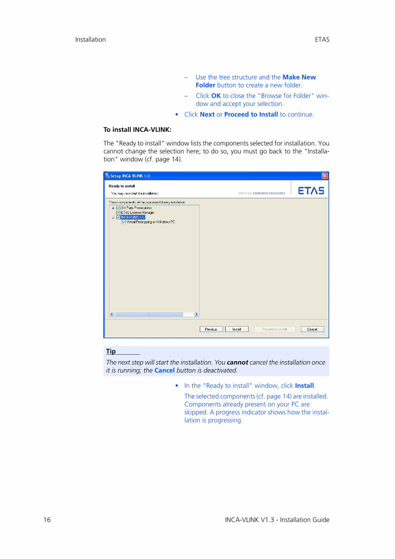
The "Ready to install" window lists the components selected for installation. Youcannot change the selection here; to do so, you must go back to the "Installa-tion" window (cf. page 14).
• In the "Ready to install" window, click Install.
The selected components (cf. page 14) are installed. Components already present on your PC are skipped. A progress indicator shows how the instal-lation is progressing.
Tip
The next step will start the installation. You cannot cancel the installation once it is running; the Cancel button is deactivated.
INCA-VLINK V1.3 - Installation Guide

ETAS Installation
To connect INCA-VLINK and MATLAB/Simulink:
After the installation is completed, the "Association with MATLAB" windowopens. It offers all supported MATLAB/Simulink installations (R2009a and higher)available on your system for selection (A in the screenshot below). Even if noMATLAB/Simulink installation is found, the "Association with MATLAB" windowopens (B in the screenshot).
• In the "Association with Matlab" window, select one of the existing MATLAB/Simulink installations.
You can select none, one, or several installations.
Cancel closes the window without establishing an association to MATLAB/Simulink. INCA-VLINK is installed nevertheless, but you must associate the program to MATLAB/Simulink manually before you can use it. See section 2.2.2 for details.
• Click OK.
If at least one selected MATLAB/Simulink installation is R2011a or later, a message window opens and informs you that the legacy ASAM-MCD-2MC generation is only partly compatible with R2011a and higher and cannot be used with R2013b and above.
• Read the message text carefully, then click OK.
INCA-VLINK is associated with the selected MATLAB/Simulink installation(s).
You can change the MATLAB/Simulink version asso-ciated with INCA-VLINK later; the procedure is described in section 2.2.2.
Tip
If you want to use a network installation of MATLAB/Simulink, click on the Help button and follow the instructions given in the message window.
(A)
(B)
INCA-VLINK V1.3 - Installation Guide 17

18
Installation ETAS
To complete the installation:
Once all components have been installed successfully, you are prompted to endthe installation.
• It is recommended that you activate the Show readme when setup is closed option
• Click on Finish to end the installation.
In the Windows Start menu, the INCA-VLINK 1.3 folder with the followingentries is created in the ETAS program group:
• Associate to Matlab
Connects a selectable MATLAB/Simulink installation with INCA-VLINK (see section 2.2.2).
This is necessary if MATLAB/Simulink is newly installed without INCA-VLINK being newly installed at the same time.
• Associate to RTA-OSEK
Connects RTA-OSEK with INCA-VLINK.
• INCA-VLINK Manuals
Opens the INCA-VLINK documentation directory.
• Uninstall INCA-VLINK
The uninstall routine is started (see section 2.4).
The ETAS License Manager has another separate folder License Managementin the ETAS program group of the Start menu.
2.2.2 Manual Association with MATLAB/Simulink
If MATLAB/Simulink was not present during INCA-VLINK installation, or if a newversion of MATLAB/Simulink is installed after INCA-VLINK, you must associateINCA-VLINK and MATLAB/Simulink manually.
To associate INCA-VLINK and MATLAB/Simulink manually:
• Install MATLAB/Simulink as described in the relevant installation instructions.
• To associate INCA-VLINK with MATLAB/Simulink, open the Windows Start menu, go to the INCA-VLINK 1.3 folder and select Associate to Matlab.
Tip
If you want to use a network installation of MATLAB/Simulink, click on the Help button and follow the instructions given in the message window.
INCA-VLINK V1.3 - Installation Guide

ETAS Installation
The "Association with Matlab" window opens. It offers all supported MATLAB/Simulink installations available on your system for selection.
• In the "Association with Matlab" window, select one or more MATLAB/Simulink installations.
• Click OK to continue.
If at least one selected MATLAB/Simulink installation is R2011a or later, a message window opens and informs you that the legacy ASAM-MCD-2MC generation is only partly compatible with R2011a and higher and cannot be used with R2013b and above.
• Read the message text carefully, then click OK.
INCA-VLINK and the selected MATLAB/Simulink installation are connected.
2.2.3 Prerequisites for Calibration on a Windows PC
Calibration on the Windows PC with INCA-VLINK requires RTA-OSEK Tools andRTA-OSEK for PC. These products will be installed as a part of the ETAS VirtualOS Execution Platform installation (B in Fig. 2-1 on page 11) on the productDVD. In addition, the installation contains the configurator and the generator forstimuli signals, the stimuli editor.
The installation routine installs the RTA-OSEK Tools and RTA-OSEK for PC to theC:\RTA directory on your computer. The stimuli editor is installed to a custom-izable location. In the Windows Start menu, the ETAS Virtual OS ExecutionPlatform 1.3 folder with the following entries entry is created in the ETAS pro-gram group.
• Signal Configuration Editor
Opens the signal configuration editor where you can configure stimuli sig-nals.
• Uninstall ETAS Virtual OS Execution Platform
The uninstallation routine is started (see section 2.4).
INCA-VLINK V1.3 - Installation Guide 19

20
Installation ETAS
• Virtual Prototyping
Checks the installations of RTA-OSEK for PC and RTA-OSEK tools, and installs/starts the VRTA server service. If the check fails, hints for trouble-shooting are given.
2.2.4 Command-Line Installation
When you start the INCA-VLINK installation from a command line, you can useseveral command-line parameters to customize the installation.
Each execution of Setup.exe writes a log file %appdata%1\ETAS\SETUP\<date_time> Setup.log.
/silent
Silent installation mode. With this installation mode, no dialog windows requiring user information open.
Default values are used for all information normally requested in installa-tion windows. Error messages are hidden, too.
/EULAAccepted
Accepts the license agreement.
The text of the license agreement is provided on the installation disk, in the EULA subfolders.
/SafetyHintsAccepted
Accepts the safety hints.
The text of the safety hints is provided on the installation disk, in the SafetyHints subfolders.
/NoRestart
Suppresses a computer restart that may be required at the end of the installation. If a reboot is suppressed, a log message is issued.
/AllowRestart
Allows a computer reboot restart that may be required at the end of the installation. A restart is performed without further notice.
/Debug
Writes additional log files for *.msi packages.
These files are stored in the %appdata%2\ETAS\SETUP folder.
1. %appdata% = C:\Documents and Settings\<username>\Application Data\ (Windows XP)C:\Users\<username>\AppData\Roaming (Windows 7)
Tip
To accept EULA and safety hints (cf. page 13) during silent installation, you must use the command-line parameters /EULAAccepted and /SafetyHintsAccepted.To deal with a possible request for a computer restart, you must use either the /NoRestart or the /AllowRestart command-line parameter.
INCA-VLINK V1.3 - Installation Guide

ETAS Installation
/DefaultSettings
Allows to specify an own XML file with default settings (instead of using InstallationDefaultSettings.xml), e.g., the following:
You can specify a relative path if the file is relative to Setup.exe, other-wise you have to specify an absolute path.
Syntax: /DefaultSettings:"<path>\<filename>.xml"
/uninstall
Uninstalls INCA-VLINK. Can be combined with /silent for uninstalla-tion without user interaction.
/Repair
In combination with /Silent, the repair process is triggered. Otherwise, the maintenance mode is triggered.
Examples:
Setup.exe /silent /EULAAccepted /SafetyHintsAccepted
Triggers a silent installation.
"C:\Program Files\ETAS\GENericSetup\Blockset INCA-VLINK\1.3.<x>.<y>\Setup.exe" /uninstall /Debug
Triggers a non-silent uninstallation and writes additional logs.
Setup.exe /DefaultSettings:”D:\myOwnSettings.xml”
Triggers a non-silent installation that uses your own default settings for the installation.
2. %appdata% = C:\Documents and Settings\<username>\Application Data\ (Windows XP)C:\Users\<username>\AppData\Roaming (Windows 7)
Variable Meaning See also
PRODINSTDIR installation directory
page 15PRODUSERDOCUMENTSDIR data directory
COMPILERDIR compiler directory
Tip
/Uninstall and /Repair cannot be used with setup.exe in the instal-lation location. You must use the setup.exe file provided in the C:\<programs>\ETAS\GENericSetup\Blockset INCA-VLINK\1.3.<x>.<y> folder.
<programs> = Program Files (x86) (64 bit OS) or Program Files (32 bit OS)
INCA-VLINK V1.3 - Installation Guide 21

22
Installation ETAS
2.3 Setting the Licensing Behavior
The INCA-VLINK installation includes an installation of the ETAS license manager.You can define the way in which INCA-VLINK (and other ETAS software pro-grams) accesses the required licenses in the [Licensing] section of an *.inifile.
The folder Installation\INCA-VLINK\Packages\Blockset INCA-VLINK_Licensing* on your installation disk contains such an *.inifile, i.e. Licensing.ini.
General Procedure
The procedure to edit the Licensing.ini file and start the installationdepends on the original location of the installation files.
The installation files are placed in a directory where you cannot edit them: Use one of the following procedures.
• Copy all installation files to a directory where you can edit the files.
There, edit Licensing.ini (cf. page 22), then start the installation via double-click on Autostart.exe or Setup.exe (cf. section 2.2.1) or via command line (cf. section 2.2.4).
• Copy only Licensing.ini to a directory where you can edit the file.
There, edit Licensing.ini (cf. page 22). Create your own XML file with default settings (cf. page 21) and enter the location of your edited Licensing.ini file in the LIMA_INFILE variable:
<Variable ↵name="LIMA_INIFILE" ↵defaultValue="<path>\Licensing.ini" ↵validation="fileExists" />
Start the installation via command line (cf. section 2.2.4). and use /DefaultSettings:"<path>\<filename>.xml" to add your own XML file and with that your License.ini file.
The installation files are placed in a directory where you can edit them:Edit the Licensing.ini file (cf. page 22) and start the installation.
Editing Licensing.ini
To define the access to the required licenses:
• Open the Licensing.ini file with a text editor.
• Modify the settings in the [Licensing] section as desired.
The parameters and their settings are described below.
• Save your changes.
The following parameters may be used:
• LicenseFileName
Defines the absolute path and file name of the license file which is to be added.
INCA-VLINK V1.3 - Installation Guide

ETAS Installation
• LicensesToBorrow
You can use this setting if licenses can be borrowed from a license server. To enable the borrow mechanism, you must enter the name of the prod-uct or features license (e.g., INCA-VLINK). If you enter more than one license, the license names must be separated by blanks.
INCA-VLINK uses the following licenses:
• BorrowExpiryMode
Defines the way in which the expiration of the borrow status is given. Possible values are:
– Date
If the BorrowExpiryMode is set to Date, the borrow period will expire at a certain date which is specified under BorrowExpiry-Date.
– Interval
If the BorrowExpiryMode is set to Interval, the borrow period will expire after a certain number of days which is specified under BorrowExpiryInterval.
• BorrowExpiryDate
If the BorrowExpiryMode is set to Date, this parameter specifies the date when the borrow period expires. The format is yyyy-mm-dd.
• BorrowExpiryInterval
If the BorrowExpiryMode is set to Interval, this parameter specifies the length of the borrow period in days.
• ExecuteBorrowAutomaticExtensionInterval
Defines at what point of time the borrow period will be automatically extended. This parameter specifies the number of days before the expira-tion of the current borrow period. When this time is reached, the borrow period is automatically extended to the interval specified under BorrowAutomaticExtensionInterval.
• BorrowAutomaticExtensionInterval
This parameter specifies the borrow interval in days that is applied when an automatic extension of the borrow period is executed (as defined under ExecuteBorrowAutomaticExtensionInterval).
License name functionality
BLOCKSET_PC target connector for virtual prototyping
BLOCKSET base functionality
INCA-VIP ETAS virtual OS execution platform
INCA-VLINK V1.3 - Installation Guide 23

24
Installation ETAS
• ImmediateBorrow
You can define that a license is automatically borrowed. Possible values are:
– True
The license is borrowed automatically at installation time.
– False
The license will be borrowed at the first time when the program con-nects to the license server.
• CustomLicenseFolder
Due to the fact that the default location for added license files (e.g., C:\Documents and Settings\All Users\Application Data\ETAS\FlexNet for Windows XP) is only writeable for users with admin rights, a different path for the license file folder may be specified with this parameter.
The following example defines that borrowing is enabled for all INCA-VLINKparts. The licenses will be borrowed when INCA-VLINK is started for the firsttime; by default the licenses expire after 100 days.
[Licensing]
LicenseFileName = ’d:\licenses\MyLicense.lic’
LicensesToBorrow = ’BLOCKSET BLOCKSET_PC’
BorrowExpiryMode = ’Interval’
BorrowExpiryInterval = ’100’
ImmediateBorrow = ’false’
2.4 Uninstalling INCA-VLINK or the ETAS Virtual OS Execution Platform
If you uninstall INCA-VLINK or the ETAS Virtual OS Execution Platform, all com-ponents are uninstalled automatically.
Use one of the following ways to start the uninstall process:
1. The Uninstall INCA-VLINK function in the INCA-VLINK program group in the Windows Start menu.
2. The Uninstall ETAS Virtual OS Execution Platform function in the ETAS Virtual OS Execution Platform program group In the Windows Start menu.
3. The Add/Remove Programs or Programs and Features icon in the Windows Control Panel.
Tip
ImmediateBorrow=’True’ works only for the user who per-forms the installation. Other users who work on the same computer do not own the borrowed license.
INCA-VLINK V1.3 - Installation Guide

ETAS Installation
To uninstall INCA-VLINK or the ETAS Virtual OS Execution Platform:
• Start the uninstall procedure.
The ETAS installer is launched.
You can use the Next button to get to the next uninstallation window; Back to get to the previous window, and Cancel to cancel uninstallation.
• Click Next to check if your computer meets the sys-tem requirements for INCA-VLINK or ETAS Virtual OS Execution Platform uninstallation.
The result is displayed in the "System Check" win-dow.
If the system requirements for uninstallation are met, the "Ready to uninstall" window opens. It lists the components that will be uninstalled. You can-
INCA-VLINK V1.3 - Installation Guide 25

26
Installation ETAS
not change the selection.
• Click Uninstall to actually uninstall INCA-VLINK or the ETAS Virtual OS Execution Platform.
A progress indicator shows how the uninstallation is progressing.
Once all components have been uninstalled, a suc-cess window opens.
• Click Finish to end the uninstallation.
Tip
The next step will start the uninstallation. You cannot cancel uninstallation once it is running; the Cancel button is deactivated.
INCA-VLINK V1.3 - Installation Guide

ETAS Licensing the Software
3 Licensing the Software
To be able to work with an ETAS software product, you require a license. Thissection contains basic details on this subject.
• "ETAS License Models" on page 27
• "How to Get a License" on page 27
• "The License File" on page 29
• "Grace Mode" on page 31
• "The "Expiration Warning" Window" on page 31
• "Borrowing a License" on page 32
Details concerning the scope of the licenses and other legal aspects can be foundin "Terms and Conditions".
3.1 ETAS License Models
There are three different license models available for licensing your ETAS soft-ware:
Machine-Named License, Local
• A license of this type is managed by the user him/herself.
• As it is linked to a particular PC (better: to the MAC address of the Ether-net adapter), it is valid wherever the PC is used.
• When you change your PC, you require a new license.
User-Named License, Server-Based
• The licenses (of a department or company) are managed centrally on a server by a designated person.
• The license is linked to the MAC address of the server and to the user name with which the user is registered in the network.
• If the relevant PC is disconnected from the network, the license can be "borrowed."
Concurrent (or Floating) License, Server-Based
Most of what is true of the user-named license applies to this type of license. Thedifference is that here several users share a limited number of licenses.
3.2 How to Get a License
If your company has a tool coordinator and server-based license management forETAS software, contact this person. Otherwise (in the case of a machine-namedlicense) you obtain your license from the ETAS license portal (the URL is shownon your Entitlement Certificate).
INCA-VLINK V1.3 - Installation Guide 27

28
Licensing the Software ETAS
There are three ways of logging in on the welcome page:
• Activation ID
Once you have logged in, a specific activation1 is visible and can be man-aged – the activation ID is shown on your Entitlement Certificate.
• Entitlement ID
All activations of the entitlement2 are visible and can be managed (e.g. for a company with just one entitlement).
• E-mail and password
All activations of the entitlements assigned to the user account are visible and can be managed (e.g. for a tool coordinator responsible for several entitlements).
If you need help in the portal, click the Help link.
What Information is Required?
Information on the hosts must be entered to activate licenses:
• Machine-named license
The MAC address of the Ethernet adapter to which the license is to be bound is required here
• User-named license
Here, you need a server host or a server triad as well as a user name.
• Concurrent (floating) license
Here, you need a server host or a server triad.
License File
The result of your activities is the provision of a file <name>.lic with which youcan license your software in the ETAS License Manager.
1. The activations refer to a specific product, its license conditions, the available number of licenses and other details required for generating a license. Activa-tions are identified uniquely with activation IDs.
2. An entitlement shows the authorizations you have as a user; it stands for the right to own one or more licenses for a product. It is a kind of account of rights of use for software from which you can take licenses as you need to.
Tip
If this data changes (e.g. due to changes in the hardware or a change of user), the license must be given a "rehost". This procedure is also described in the portal help file.
INCA-VLINK V1.3 - Installation Guide

ETAS Licensing the Software
3.3 The License File
To check the license status:
• In the Windows Start menu, select Programs → ETAS → License Management → ETAS License Manager.
• Click Continue.
The ETAS License Manager contains one entry for each installed product. The symbol at the beginning of the entry and the "Status" column entry indicate whether a valid license has already been obtained or not.
INCA-VLINK V1.3 - Installation Guide 29

30
Licensing the Software ETAS
To add a license file:
• Open the ETAS License Manager (cf. page 29) and select File → Add Licensing File.
The "Install License" dialog window opens.
• Next to the "Select License File" field click the ... button.
• In the file selection window, select the license file and click Open.
The "Install License" dialog window shows infor-mation on the selected license.
• Confirm with OK.
The license just added is now listed in the ETAS License Manager. A green symbol before the entry shows that the license is valid.
• Close the ETAS License Manager.
Tip
The "Version" column shows the version number of the license, not the version number of the software.
INCA-VLINK V1.3 - Installation Guide
ETAS Licensing the Software
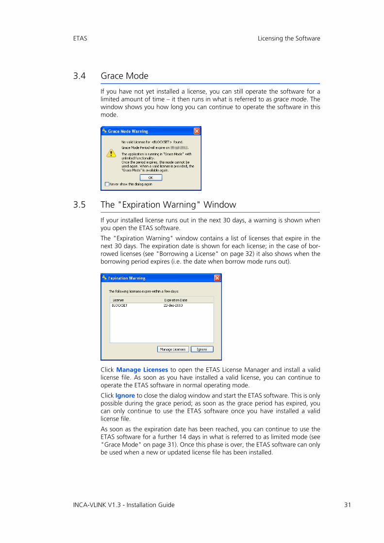
3.4 Grace Mode
If you have not yet installed a license, you can still operate the software for alimited amount of time – it then runs in what is referred to as grace mode. Thewindow shows you how long you can continue to operate the software in thismode.
3.5 The "Expiration Warning" Window
If your installed license runs out in the next 30 days, a warning is shown whenyou open the ETAS software.
The "Expiration Warning" window contains a list of licenses that expire in thenext 30 days. The expiration date is shown for each license; in the case of bor-rowed licenses (see "Borrowing a License" on page 32) it also shows when theborrowing period expires (i.e. the date when borrow mode runs out).
Click Manage Licenses to open the ETAS License Manager and install a validlicense file. As soon as you have installed a valid license, you can continue tooperate the ETAS software in normal operating mode.
Click Ignore to close the dialog window and start the ETAS software. This is onlypossible during the grace period; as soon as the grace period has expired, youcan only continue to use the ETAS software once you have installed a validlicense file.
As soon as the expiration date has been reached, you can continue to use theETAS software for a further 14 days in what is referred to as limited mode (see"Grace Mode" on page 31). Once this phase is over, the ETAS software can onlybe used when a new or updated license file has been installed.
INCA-VLINK V1.3 - Installation Guide 31

32
Licensing the Software ETAS
3.6 Borrowing a License
The borrowing mechanism makes it possible to work offline even when using aserver-based license (i.e. without being connected to the license server).
To borrow a license, proceed as follows:
To borrow a license
• Make sure that the ETAS software the license of which you want to borrow is not open.
• Select the license you want to borrow in the "License Listing" table of the ETAS License Manager.
• Right-click the license and select Borrow License from the context menu
The "Select Borrow end date" dialog window opens.
Tip
You can only borrow a license if a server-based license is being used!
INCA-VLINK V1.3 - Installation Guide

ETAS Licensing the Software
• Select the date until which you want to borrow the license from the calendar displayed and click OK.
The text in the "Source" column of the ETAS License Manager changes from SERVER to BOR-ROW, and the expiration date of the borrowed license is displayed.
You can now use the relevant ETAS software offline until the expiration date ofthe borrowed license has been reached.
If you want to use the ETAS software longer than you had originally planned, youcan borrow the license again. If you stop using the ETAS software earlier thanplanned, you can return the license to the license server early (Return Licensefrom a license’s context menu). A borrowed license can only be returned by theperson that borrowed it; it cannot be returned by another person.
INCA-VLINK V1.3 - Installation Guide 33

34
INCA-VLINK Quick Guide ETAS
4 INCA-VLINK Quick Guide
4.1 Introduction
This chapter is intended to provide a quick guide to the most important featuresof INCA-VLINK V1.3. The examples, displayed in the form of flowcharts, provideyou with an overview of the program functionality and operating mode.
This chapter does not explain how to work with Simulink in general.
Below, you find a short explanation of the most important abbreviations usedhere.
• DB – Database
• EE – Experiment Environment
• HC – Hardware Configurator
• HW – Hardware
• HWS – Hardware System
• OS – Operating system
• VP – Virtual Prototyping
• WS – Workspace
INCA-VLINK V1.3 - Installation Guide

ETAS INCA-VLINK Quick Guide
4.2 Preparing the Model
INCA-VLINK models require a special system target and a fixed-step solver. 1 2
Fig. 4-1 Preparing the Simulink Model
1. MATLAB/Simulink R2010b or older2. MATLAB/Simulink R2011a or newer
Preparing the SimulinkModel
Select systemtarget file
Select solver
Create and saveSimulink model
MATLAB or Simulink: select File → New → Model
Simulink: File → Save
Simulink: press <CTRL> + <E>
select System target file
matching template makefile set automatically
open "Solver" node
selectFixed-step solver
open "Real-Time Work-shop"1. / "Code Generation"2. node
INCA-VLINK V1.3 - Installation Guide 35
36
INCA-VLINK Quick Guide ETAS
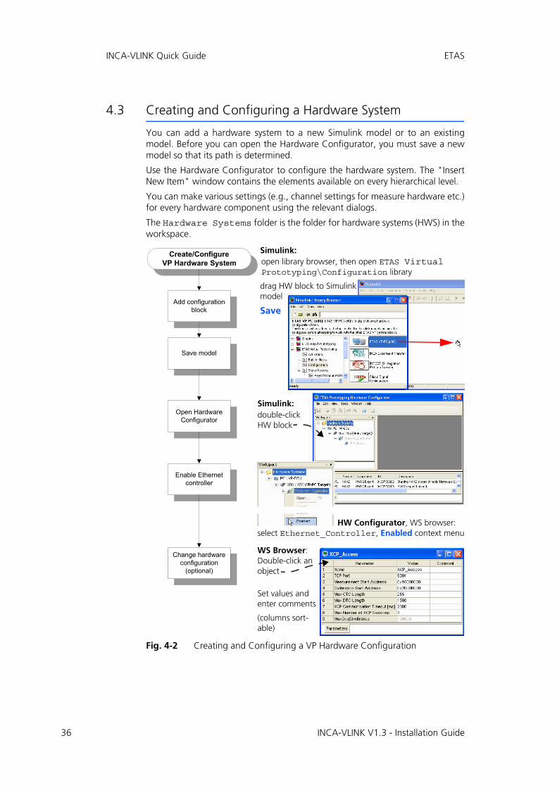
4.3 Creating and Configuring a Hardware System
You can add a hardware system to a new Simulink model or to an existingmodel. Before you can open the Hardware Configurator, you must save a newmodel so that its path is determined.
Use the Hardware Configurator to configure the hardware system. The "InsertNew Item" window contains the elements available on every hierarchical level.
You can make various settings (e.g., channel settings for measure hardware etc.)for every hardware component using the relevant dialogs.
The Hardware Systems folder is the folder for hardware systems (HWS) in theworkspace.
Fig. 4-2 Creating and Configuring a VP Hardware Configuration
Create/ConfigureVP Hardware System
Save model
Enable Ethernetcontroller
Add configurationblock
Change hardwareconfiguration
(optional)
Open HardwareConfigurator
WS Browser: Double-click an object
Set values and enter comments
(columns sort-able)
HW Configurator, WS browser: select Ethernet_Controller, Enabled context menu
Simulink: open library browser, then open ETAS Virtual Prototyping\Configuration library
drag HW block to Simulinkmodel
Save
Simulink:double-click HW block
INCA-VLINK V1.3 - Installation Guide

ETAS INCA-VLINK Quick Guide
4.3.1 Importing a Hardware System
As an alternative to manual creation and setup of a HWS, you can import a hard-ware description, *.hwx, created with INTECRIO, INTECRIO-RLINK, INCA-VLINKor ASCET-RP into a new, or an existing, hardware system.
The file extension *.hwx is used for two description formats (HWX1 and HWX2).The HWX1 format can only be imported in an RP hardware configuration, it isnot possible to import an HWX1 file in a VP hardware configuration. INCA-VLINKrecognizes the format automatically and starts (HWX2) or aborts (HWX1) theimport.
After import file selection, HWX2 import is aided by a wizard (see Fig. 4-3).
Fig. 4-3 Importing a HWX2 hardware description (*.hwx file)
4.4 Specifying the Model
This section focuses on how to use the blocks and features provided byINCA-VLINK.
For information on standard MATLAB/Simulink functionality, refer to the MATLAB/Simulink documentation.
Import HWX2 hardwaredescription
Select *.hwx file
Set import options
Perform import
WS Browser: select start node, i.e. Hard-ware Systems folder or existing hardware system or existing target (ES113x/ES910/X86) or existing board/controller/device,Import context menu
HW description is imported; information, warnings, errors are shown in "Message" tab of "Log Window"
Windows file selection window: select *.hwx file, Open
select import type, Finish
INCA-VLINK V1.3 - Installation Guide 37

38
INCA-VLINK Quick Guide ETAS
4.4.1 Adding Activation Task Blocks
The activation task blocks are provided in the "ETAS Virtual Prototyping" library,"Activation" sub-library.
Fig. 4-4 Adding and configuring activation task blocks
Adding / ConfiguringActivation Task Blocks
Configure taskblock
Connect task blockto trigger input
Add task block
Simulink: double-click OS * Task block
"Source Block Parameters: OS * Task" window: set parameters
(see online help for additional information)
optional: optional:
Simulink: open Simulink Library Browser, go to ETAS * Prototyping\Activation
add OS Exit Task or OS Init Task or OS Timer Task to model
Simulink: use standard means to connect task block to trigger input of function-call subsystem
C identifier; mapped to associated task
defines point in task sequence when this task runs
execution period, delay and priority (no. ↑ prio. ↑) of timer task
INCA-VLINK V1.3 - Installation Guide

ETAS INCA-VLINK Quick Guide
4.4.2 Adding the System Time Block
The OS System Time block provides a data output port for the target system timeto be read. The block is provided in the "ETAS Virtual Prototyping" library, "Acti-vation" sub-library.
Fig. 4-5 Adding and configuring an OS System Time block
4.5 Stimuli Signal Configuration
INCA-VLINK enables you to define a stimuli signal configuration for use with yourcontroller function.
Adding / ConfiguringOS System Time Block
Connectsystem time block
to model
Add system timeblock
optional: optional:
Simulink: open Simulink Library Browser, go to ETAS * Prototyping\Activation
add OS System Time to model
Simulink: use standard means to connect OS System Time block to the model.
INCA-VLINK V1.3 - Installation Guide 39

40
INCA-VLINK Quick Guide ETAS
4.5.1 Stimuli Signal Configuration Block
Fig. 4-6 Adding a Signal Configuration block and MDF file(s)
Add Stimuli Signal Config-uration Block + MDF File
Add 1 StimuliSignal
Configuration block
Open VP model
Open SignalConfiguration
Editor
Add MDF file
MATLAB/Simulink: open model
Simulink: open library browser, go to ETAS Virtual Prototyping\ Configuration
add Stimuli Signal Configuration to model
Simulink: double-click Stimuli Signal Configuration
Signal Configuration Editor: select File → Add MDF File
file selection window: select MDF file(s), Open
"Channel Groups" field shows(a) MDF files(b) channels (signal groups) per
MDF file
(a)
(b)
INCA-VLINK V1.3 - Installation Guide

ETAS INCA-VLINK Quick Guide
Fig. 4-7 Managing MDF files
Managing MDF Files
Replacing MDFfiles
Removing MDFfiles
open Signal Configuration Editor
Select File → Remove MDF File
select file(s) to be removed,Remove
Select File → Replace MDF File
a) select file to be replaced, click b) file selection dialog: select replacing MDF file, Open
decide: keep mapping?
if desired, repeat a) and b)
Signal Configuration Editor: click Save and Close
OK
INCA-VLINK V1.3 - Installation Guide 41

42
INCA-VLINK Quick Guide ETAS
Fig. 4-8 Signals for stimuli configuration
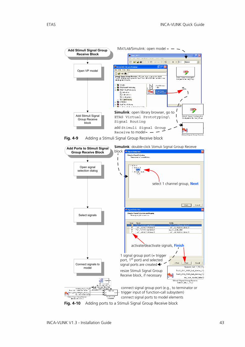
4.5.2 Stimuli Signal Group Receive Block
The Stimuli Signal Group Receive block enables you to create ports by mappingsignals defined in existing MDF files to the block. You can route signals via theseports to objects within the control function.
Selecting Signals for Stimuli Configuration
Set channel group parameters
Select channel group
(= signal group)
Select / deselect signals
Rename model labels
Set up signals
open Signal Configuration Editor
select channel group
select: filter "Available Signals" list (opt.), select signal(s), click on >>
set parameters
"Model" column: double-click cell to be renamed
enter new model label name, <RETURN>
Signal Configuration Editor: click Save and Close
old label now unmapped
"Value" column: double-click cell, enter value, <RETURN> entered value shown during measurement
"Convert" column: activate option implementation value is converted to physical value
deselect: select signal in "Signal Assignment" pane, <<
INCA-VLINK V1.3 - Installation Guide
ETAS INCA-VLINK Quick Guide
Fig. 4-9 Adding a Stimuli Signal Group Receive block
Fig. 4-10 Adding ports to a Stimuli Signal Group Receive block
MATLAB/Simulink: open modelAdd Stimuli Signal GroupReceive Block
Add Stimuli SignalGroup Receive
block
Open VP model
Simulink: open library browser, go to ETAS Virtual Prototyping\ Signal Routing
add Stimuli Signal Group Receive to model
Simulink: double-click Stimuli Signal Group Receive block
Add Ports to Stimuli SignalGroup Receive Block
Select signals
Open signalselection dialog
Connect signals tomodel
select 1 channel group, Next
connect signal group port (e.g., to terminator or trigger input of function-call subsystem)connect signal ports to model elements
1 signal group port (= trigger port, 1st port) and selected signal ports are created
resize Stimuli Signal Group Receive block, if necessary
activate/deactivate signals, Finish
INCA-VLINK V1.3 - Installation Guide 43

44
INCA-VLINK Quick Guide ETAS
Further mapping of signals to ports is done in the Signal Configuration Editor.
Fig. 4-11 Mapping signals to ports automatically
Mapping Signals to Ports:Automatically
Auto MappingSettings
Open SignalConfiguration Editor
Auto MappingPreview
Auto MapChannels
Use carefully; may destroyexisting mappings
select Options → Auto Mapping Settings
select mapping rule
activate and set up pre-fix/suffix treatment
(see help for details)
OK
open Signal Configuration Editor
select Options → Auto Mapping preview or
"Log Window" lists expected automapping failures
select Options → Auto Map Channels or
if possible, signals are mapped to ports; "Log Window" lists automapping ambiguities and failures
Signal Configuration Editor: click Save and Close
INCA-VLINK V1.3 - Installation Guide
ETAS INCA-VLINK Quick Guide
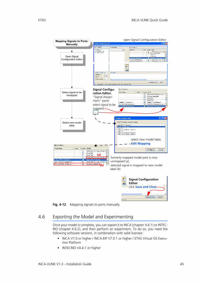
Fig. 4-12 Mapping signals to ports manually
4.6 Exporting the Model and Experimenting
Once your model is complete, you can export it to INCA (chapter 4.6.1) or INTEC-RIO (chapter 4.6.2), and then perform an experiment. To do so, you need thefollowing software versions, in combination with valid licenses:
• INCA V7.0 or higher / INCA-EIP V7.0.1 or higher / ETAS Virtual OS Execu-tion Platform
• INTECRIO V4.4.1 or higher
Mapping Signals to Ports:Manually
Select signal to beremapped
Open SignalConfiguration Editor
Select new modellabel
open Signal Configuration Editor
Signal Configuration Editor: click Save and Close
Signal Configu-ration Editor, "Signal Assign-ment" pane:select signal to be mapped,
select new model label, Edit Mapping
formerly mapped model port is now unmapped (a), selected signal is mapped to new model label (b)
(a)
(b)
INCA-VLINK V1.3 - Installation Guide 45

46
INCA-VLINK Quick Guide ETAS
4.6.1 Export / Experiment – INCA
Fig. 4-13 Exporting the model to INCA
Exporting to INCA
Build model
Add INCA Experiment
Transfer block
Start INCA transfer
Select INCA project
Select INCA database
Select INCA workspace
Perform transfer
Simulink: open Simulink Library Browser, go to ETAS * Prototyping\Configuration(* = Rapid or Virtual)add block INCA Experiment Transfer to model
Simulink: press <CTRL> + <B> or select menu option:Tools→Realtime Workshop→Build Model (≤ R2010b)Tools→Code Generation→Build Model (R2011a–12a)Code→C/C++ Code→Build (≥ R2012b)
Simulink: double-click INCA Experiment Transfer block
"INCA Project Transfer" window:Browse button (a)
(a)(b)(c)
select folder of existing INCA DBoruse Make New Folder to create new DB
click OKINCA opens with selected DB; DB listed in "INCA Project Transfer" window
"INCA Project Transfer" win-dow:click Browse button (b)
select existing INCA WSorNew Workspace / New Folder to create WS
click OKWS listed in "INCA Project Transfer" window
"INCA Project Transfer" win-dow:click Browse button (c)
select existing INCA projectorNew INCA Project / New Folder to create project
click OK
"INCA Project Transfer" window: Start Project Transfer
INCA-VLINK V1.3 - Installation Guide

ETAS INCA-VLINK Quick Guide
Fig. 4-14 VP Experiment in INCA (with XCP)
Open experiment / initialize hardware
VP Experiment in INCA (with XCP)
Set up hardware device
Create and define experiment
Run <model>.bat file
Experiment in INCA
Perform upload
INCA: select DB folder, open Edit menu or folder context menu, Add → Experiment
select experiment
OK
INCA EE: Hardware → Initialize hardware Hardware → Manage memory pages
Windows Explorer: go to folder with Simulink model, run <model name>.bat virtual ECU is started
INCA:Experiment → Run Experiment INCA EE opens
set up and perform INCA experiment (cf. INCA online help)
select workspace in "1 Database" list, Experiment → Change Experiment
experiment added to WS
select Device → Configure hardware
remove ( ) existing hardware devices
add ( ) Ethernet-System\XCP hardware device and select transferred project(see also INCA online help)
(a)(b)
(c)
go to "Enhanced" tab (a), select action Upload (b), Do it (c), Close
INCA-VLINK V1.3 - Installation Guide 47

48
INCA-VLINK Quick Guide ETAS
Fig. 4-15 VP Experiment in INCA / INCA-EIP (without XCP)
VP Experiment in INCA (without XCP)
Set up hardware device
Create and define experiment
Experiment in INCA
Open experiment / initialize hardware
INCA: select DB folder, open Edit menu or folder context menu, Add → Experiment
select experiment
OK
INCA EE: Hardware → Initialize hardware
INCA:Experiment → Run Experiment INCA EE opens
set up and perform INCA experiment (cf. INCA online help)
select workspace in "1 Database" list, Experiment → Change Experiment
experiment added to WS
select Device → Configure hardware
add ( ) PC/Simulation System\Virtual prototyping HW device and select transferred project(see also INCA online help)
INCA-VLINK V1.3 - Installation Guide

ETAS INCA-VLINK Quick Guide
4.6.2 Export / Experiment – INTECRIO
Fig. 4-16 Exporting the model to INTECRIO, experimenting in INTECRIO
Export to / Experiment in INTECRIO
Build model (optional)
Add INTECRIO Integration Platform
Transfer block
Start INTECRIO transfer
Perform transfer
Experiment in INTECRIO
Select workspace directory
Simulink: open Simulink Library Browser, go to ETAS * Prototyping\Configuration(* = Rapid or Virtual)
add block INTECRIO Integration Platform Transfer to model
Simulink: double-click INTECRIO Integration Platform Transfer block
"INTECRIO Integration Platform" window:
enter or select (via Browse) an empty directory for the INTECRIO WS
click Start transfer
INTECRIO WS created
model imported and built
WS opens in INTEC-RIO
INTECRIO:optional: adjust INTECRIO system project (see INTECRIO online help)
start experiment(see EE online help)
Simulink: press <CTRL> + <B> or select menu option:Tools→Realtime Workshop→Build Model (≤ R2010b)Tools→Code Generation→Build Model (R2011a–12a)Code→C/C++ Code→Build (≥ R2012b)
INCA-VLINK V1.3 - Installation Guide 49
50
Glossary ETAS
5 Glossary
This glossary contains explanations of the technical terms and abbreviations usedin the INCA-VLINK documentation. While some terms are also used in a moregeneral sense, this glossary specifically addresses the meaning of those terms asthey are applied to calibration on Windows with INCA-VLINK.
The terms are listed in alphabetical order.
ASAM-MCD
Working Group for Standardizing Automation and Measuring Systems, including the Working Groups Measuring, Calibrating, and Diagnostics (German: Arbeitskreis zur Standardisierung von Automations- und Mess-systemen, mit den Arbeitsgruppen Messen, Calibrieren und Diagnose)
ASAM-MCD-2MC
A file format used to describe the calibration variables and measured sig-nals contained in the control unit software, and additional specific infor-mation designed to parameterize the experiment interface. ASAM-MCD-2MC is used to import the information required for this into an experi-ment (A2L file).
For further information, refer to http://www.asam.net.
CAN
Controller area network
CANdb
CAN database; CAN description file created with the CANdb data man-agement program made by the company Vector Informatik.
CPU
Central processing unit
ECU
Electronic control unit; a small embedded computer system that consists of a CPU and the associated periphery, where everything is usually located in the same housing.
ETK
emulator test probe (German: Emulator-Tastkopf)
Event
An event is an (external) trigger that initiates an action of the operating system, such as a task.
EVPT_ERT
ETAS virtual prototyping realtime target for embedded coder (RTW Embedded Coder or Embedded Coder real-time target)
EVPT_GRT
ETAS virtual prototyping realtime target (RTW or Simulink Coder real-time target)
HW
Hardware
INCA-VLINK V1.3 - Installation Guide

ETAS Glossary
INCA
ETAS measuring, calibration and diagnostics system (Integrated Calibra-tion and Acquisition Systems)
INCA-EIP
INCA add-on; allows access to the simulation node and other experimen-tal targets for INCA.
INCA-VLINK V1.3 requires INCA-EIP V7.0.1 or higher.
INCA-VLINK
INCA-VLINK is a tool that allows users to configure a virtual prototyping experiment from within MATLAB/Simulink and use it in experiments with INCA/INCA-EIP.
INTECRIO Integrated Prototyping Environment
The INTECRIO Integrated Prototyping Environment offers an integration platform that is able to combine, i.e. integrate, control algorithms whose parts have been created with different function modeling tools. It allows for creating and configuring hardware systems and the connections of these hardware systems with the control algorithms.
INTECRIO-RLINK V1.3, INCA-VLINK V1.3 and INTECRIO V4.4 share the same technical basis. INTECRIO-RLINK and INCA-VLINK provide an auto-mated transfer of their models to workspaces for the INTECRIO Integrated Prototyping Environment.
INTECRIO-RLINK
INTECRIO-RLINK is a tool that allows users to configure a rapid-prototyp-ing or virtual-prototyping experiment from within MATLAB/Simulink and use it in experiments with INCA/INCA-EIP.
LSB and lsb
Least Significant Byte (capital letters) or bit (small letters)
MATLAB®
High-performance language for technical calculations; contains mathe-matical calculations, visualization and programming in one environment.
MSB and msb
Most Significant Byte (capital letters) or bit (small letters)
NVRAM
Non-volatile RAM
OS
Operating system
OSEK
Working group for Open Systems for Electronics in Motor Vehicles (Ger-man: Offene Systeme für die Elektronik im Kraftfahrzeug)
Process
A process is a simultaneously executable functionality that is activated by the operating system. Processes are specified in modules and do not fea-ture any arguments/inputs or result values/outputs.
INCA-VLINK V1.3 - Installation Guide 51
52
Glossary ETAS
Processor
see CPU
Prototype
Completely executable file for an experimental target system. Such a pro-totype shows the software functions in practical use – entirely with differ-ent goal directions and in a different appropriation.
RTA-OSEK
ETAS real-time operating system; implements the AUTOSAR-OS V1.0 (SC-1) and OSEK/VDX OS V2.2.3 standards and is fully MISRA compliant.
RTA-OS
ETAS real-time operating system; implements the AUTOSAR R3.0 OS and OSEK/VDX OS V2.2.3 standards and is fully MISRA compliant.
RTA-RTE
AUTOSAR runtime environment by ETAS
RTIO
Real-time Input-Output
RTOS
Real-time operating system
SCOOP-IX
SCOOP Interface Exchange language.
INCA-VLINK V1.3 supports the SCOOP-IX versions V1.0, V1.1 and V1.2.
Simulink®
Tool for modeling, simulation and analysis of dynamic systems.
INCA-VLINK adds the possibility to configure virtual prototyping experi-ments and run them on ETAS hardware using INCA and INCA-EIP.
SP
service point
SW
software
Task
A task is an ordered collection of processes that can be activated by the operating system. Attributes of a task are its application modes, activation trigger, priority and modes of its scheduling. Upon activation, the pro-cesses of the task are executed in the specified order.
UDP
User datagram protocol
Virtual prototyping
Function developers create virtual prototypes of electronic vehicle func-tions and test them on the PC.
INCA-VLINK V1.3 - Installation Guide

ETAS Glossary
XCP
Universal measurement and calibration protocol; the x generalizes the various transportation layers that can be used.
INCA-VLINK V1.3 supports XCP version V1.0.
XETK
emulator test probe (ETK) with ethernet interface
XML
Extensible Markup Language
INCA-VLINK V1.3 - Installation Guide 53

54
Appendix: Troubleshooting General Problems ETAS
6 Appendix: Troubleshooting General Problems
This chapter gives some information of what you can do when problems arisethat are not specific to an individual software or hardware product.
6.1 Problems and Solutions
6.1.1 Network Adapter cannot be selected via Network Manager
Cause: APIPA is disabled
The alternative mechanism for IP addressing (APIPA) is usually enabled on allWindows systems. Network security policies, however, may request the APIPAmechanism to be disabled. In this case, you cannot use a network adapter whichis configured for DHCP to access ETAS hardware. The ETAS Network Managerdisplays a warning message.
The APIPA mechanism can be enabled by editing the Windows registry. This ispermitted only to users who have administrator privileges. It should be done onlyin coordination with your network administrator.
To enable the APIPA mechanism:
• Open the Registry Editor:
– Windows XP and Windows 7:Click Start and then click Run. Enter regedit and click OK.
– Windows Vista:Click Start, enter regedit in the entry field, and push <ENTER>.
The registry editor is displayed.
• Open the folder HKEY_LOCAL_MACHINE\SYSTEM\CurrentControlSet\Services\Tcpic\Parameters\
• Click Edit → Find to search for the key IPAuto-configurationEnabled.
If you cannot find any instances of the registry key mentioned, the APIPA mech-anism has not been disabled on your system, i.e. there is no need to enable it.Otherwise proceed with the following steps.
• Set the value of the key IPAutoconfigurationEnabled to 1 to enable the APIPA mechanism.
You may find several instances of this key in the Windows registry which either apply to the TCP/IP service in general or to a specific network adapter. You only need to change the value for the corre-sponding network adapter.
• Close the registry editor.
• Restart your workstation in order to make your changes take effect.
INCA-VLINK V1.3 - Installation Guide

ETAS Appendix: Troubleshooting General Problems
6.1.2 Search for Ethernet Hardware fails
Cause: The versions of the Hardware and the ETAS MC Software are not compatible
If you are using ETAS hardware with ETAS MC software, you can use the ETASHSP Update Tool to check the firmware version of your hardware:
• Make sure you use the ETAS HSP Update Tool with the latest HSP (Hardware Service Pack) version.
• Also use the HSP Update Tool to check whether the hardware is compat-ible with the MC software used.
• Make sure any additional drivers for that hardware are installed correctly.
You can get the required HSP from the ETAS internet pages underwww.etas.com.
If you still cannot find the hardware using the HSP Update Tool, check whetherthe hardware offers a Web interface and whether you can find using this inter-face. Otherwise check whether one of the following causes and solutions mightapply.
Cause: Personal Firewall blocks Communication
For a detailed description on problems caused by personal firewalls and possiblesolutions see "Personal Firewall blocks Communication" on page 57.
Cause: Client Software for Remote Access blocks Communication
PCs or notebooks which are used outside the ETAS hardware network some-times use a client software for remote access which might block communicationto the ETAS hardware. This can have the following causes:
• A firewall which is blocking Ethernet messages is being used (see „Cause: Personal Firewall blocks Communication“ on page 55)
• By mistake, the VPN client software used for tunneling filters messages. As an example, Cisco VPN clients with versions before V4.0.x in some cases erroneously filtered certain UDP broadcasts.
If this might be the case, please update the software of your VPN client.
Cause: ETAS Hardware hangs
Occasionally the ETAS hardware might hang. In this case switch the hardwareoff, then switch it on again to re-initialize it.
Cause: ETAS Hardware went into Sleep Mode
In order to save power, some ETAS devices will go to sleep mode if they do notsee that they are connected to another device/computer.
To solve that, connect your Ethernet cable from your computer to the "HOST"/"Sync In" port on the device. After the device turns on, connect to the deviceusing the web interface and change the settings so that the device stays alwayson. Consult the device's manual for details on how to do that.
INCA-VLINK V1.3 - Installation Guide 55

56
Appendix: Troubleshooting General Problems ETAS
Cause: Network Adapter temporarily has no IP Address
Whenever you switch from a DHCP company LAN to the ETAS hardware net-work, it takes at least 60 seconds until ETAS hardware can be found. This iscaused by the operating system’s switching from the DHCP protocol to APIPA,which is being used by the ETAS hardware.
Cause: ETAS Hardware had been connected to another Logical Net-work
If you use more than one PC or notebook for accessing the same ETAS hardware,the network adapters used must be configured to use the same logical network.If this is not possible, it is necessary to switch the ETAS hardware off and onagain between different sessions (repowering).
Cause: Device driver for network card not in operation
It is possible that the device driver of a network card is not running. In this caseyou will have to deactivate and then reactivate the network card.
To deactivate and reactivate the network card (Win XP, Win Vista):
• To deactivate the network card, select the following item from the Windows start menu:
– Windows XP: Control Panel → Network Connections
– Windows Vista:Control Panel → Network and Internet → Network and Sharing Center
• Right click on the used network adapter and select Disable in the context menu.
• In order to reactivate the network adapter right click on it again and select Enable.
To deactivate and reactivate the network card (Win 7):
• To deactivate the network card, select Control Panel → Device Manager from the Windows start menu.
• In the Device Manager, open the tree structure of the entry Network Adapters.
• Click on the used connection to open its "<connec-tion name> Status" dialog window.
• Right-click on the used network adapter and select Disable in the context menu.
• In order to reactivate the network adapter right-click on it again and select Enable.
Cause: Laptop power management deactivates the network card
The power management of a laptop computer can deactivate the network card.Therefore you should turn off power monitoring on the laptop.
INCA-VLINK V1.3 - Installation Guide

ETAS Appendix: Troubleshooting General Problems
To switch off power monitoring on the laptop:
• From the Windows Start Menu, select
– Windows XP: Control Panel → System.
Then select the Hardware tab and click on Device Manager.
– Windows 7:Control Panel → Device Manager.
• In the Device Manager open the tree structure of the entry Network Adapters.
• Right click on the used network adapter and select Properties in the context menu.
• Select the Power Management tab and deactivate the Allow the computer to turn off this device to save power option.
• Select the Advanced tab. If the property Auto-sense is included, deactivate it also.
• Click OK to apply the settings.
Cause: Automatic disruption of network connection
It is possible after a certain period of time without data traffic that the networkcard automatically interrupts the Ethernet connection. This can be prevented bysetting the registry key autodisconnect.
To set the registry key autodisconnect:
• Open the Registry Editor.
• Select under HKEY_LOCAL_MACHINE\SYSTEM\ControlSet001\Services\lanmanserver\parameters the Registry Key autodisconnect and change its value to 0xffffffff.
6.1.3 Personal Firewall blocks Communication
Cause: Permissions given through the firewall block ETAS hardware
Personal firewalls may interfere with access to ETAS Ethernet hardware. Theautomatic search for hardware typically cannot find any Ethernet hardware at all,although the configuration parameters are correct.
Certain actions in ETAS products may lead to some trouble if the firewall is notproperly parameterized, e.g. upon opening an experiment in ASCET or searchingfor hardware from within INCA or HSP.
If a firewall is blocking communication to ETAS hardware, you must either dis-able the firewall software while working with ETAS software, or the firewall mustbe configured to give the following permissions:
• Outgoing limited IP broadcasts via UDP (destination address 255.255.255.255) for destination ports 17099 or 18001
INCA-VLINK V1.3 - Installation Guide 57

58
Appendix: Troubleshooting General Problems ETAS
• Incoming limited IP broadcasts via UDP (destination IP 255.255.255.255, originating from source IP 0.0.0.0) for destination port 18001
• Directed IP broadcasts via UDP to the network configured for the ETAS application, destination ports 17099 or 18001
• Outgoing IP unicasts via UDP to any IP in network configured for the ETAS application, destination ports 17099 through 18020
• Incoming IP unicasts via UDP originating from any IP in the network con-figured for the ETAS application, source ports 17099 through 18020, destination ports 17099 through 18020
• Outgoing TCP/IP connections to the network configured for the ETAS application, destination ports 18001 through 18020
The Windows operating systems come with a built-in personal firewall. In addi-tion, it is very common to have personal firewall software from third party ven-dors, such as Symantec, McAffee or BlackIce installed. The proceedings inconfiguring the ports might differ for each personal firewall software used.Therefore please refer to the user documentation of your personal firewall soft-ware for further details.
As an example for a firewall configuration, you will find below a description onhow to configure the widely used Windows XP firewall if the hardware access isprohibited under Windows XP with Service Pack 2.
Solution for Windows XP Firewall, Users with Administrator Privi-leges
If you have administrator privileges on your PC, the following dialog windowopens if the firewall blocks an ETAS product.
Tip
The ports that have to be used in concrete use cases depend on the hard-ware used. For more precise information on the port numbers that can be used please refer to your hardware documentation.
INCA-VLINK V1.3 - Installation Guide

ETAS Appendix: Troubleshooting General Problems
To unblock a product:
• In the "Windows Security Alert" dialog window, click on Unblock.
The firewall no longer blocks the ETAS product in question (in the example: ASCET). This decision sur-vives a restart of the program, or even the PC.
Instead of waiting for the "Windows Security Alert" dialog window, you canunblock ETAS products in advance.
To unblock ETAS products in the firewall control:
• From the Windows Start Menu, select Settings → Control Panel.
• In the control panel, double-click the Windows Firewall icon to open the "Windows Firewall" dia-log window.
INCA-VLINK V1.3 - Installation Guide 59
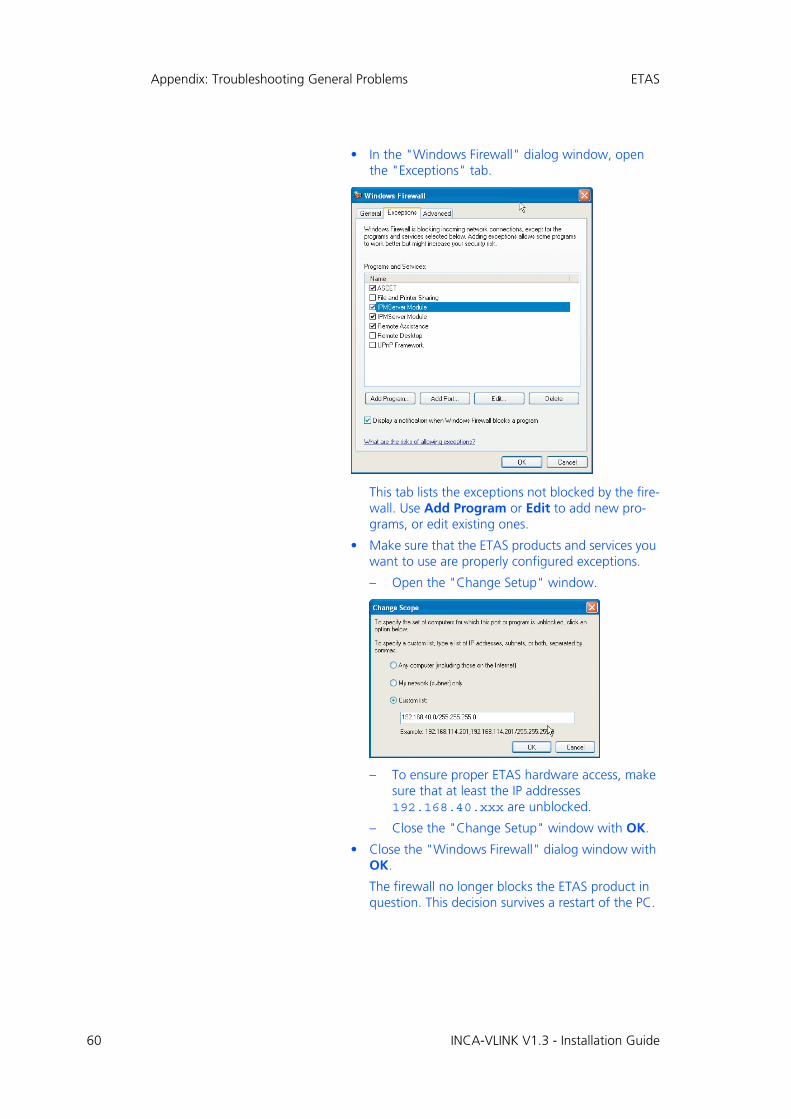
60
Appendix: Troubleshooting General Problems ETAS
• In the "Windows Firewall" dialog window, open the "Exceptions" tab.
This tab lists the exceptions not blocked by the fire-wall. Use Add Program or Edit to add new pro-grams, or edit existing ones.
• Make sure that the ETAS products and services you want to use are properly configured exceptions.
– Open the "Change Setup" window.
– To ensure proper ETAS hardware access, make sure that at least the IP addresses 192.168.40.xxx are unblocked.
– Close the "Change Setup" window with OK.
• Close the "Windows Firewall" dialog window with OK.
The firewall no longer blocks the ETAS product in question. This decision survives a restart of the PC.
INCA-VLINK V1.3 - Installation Guide

ETAS Appendix: Troubleshooting General Problems
Solution for Windows XP Firewall, Users without Administrator Privileges
This section addresses users with restricted privileges, e.g., no system changes,write restrictions, local login.
Working with an ETAS software product requires "Write" and "Modify" privi-leges within the ETAS, ETASData, and ETAS temporary directories. Otherwise,an error message opens if the product is started, and a database is opened. Inthat case, no correct operation of the ETAS product is possible because the data-base file and some *.ini files are modified during operation.
The ETAS software has to be installed by an administrator anyway. It is recom-mended that the administrator assures that the ETAS program/processes areadded to the list of the Windows XP firewall exceptions, and selected in that list,after the installation. If this is omitted, the following will happen:
• The "Window Security Alert" window opens when one of the actions conflicting with a restrictive firewall configuration is executed.
To unblock a program (no Admin privileges):
• In the "Windows Security Alert" dialog window, activate the option For this program, don’t show this message again.
• Click OK to close the window.
An administrator has to select the respective ETAS software in the "Exceptions" tab of the "Windows Firewall" dialog window to avoid further problems regarding hardware access with that ETAS product.
INCA-VLINK V1.3 - Installation Guide 61
INCA-VLINK V1.3 - Installation Guide62
ETAS Contact Addresses ETAS
7 ETAS Contact Addresses
ETAS HQ
ETAS GmbH
ETAS Subsidiaries and Technical Support
For details of your local sales office as well as your local technical support teamand product hotlines, take a look at the ETAS website:
Borsigstraße 14 Phone: +49 711 3423-0
70469 Stuttgart Fax: +49 711 3423-2106
Germany WWW: www.etas.com
ETAS subsidiaries WWW: www.etas.com/en/contact.php
ETAS technical support WWW: www.etas.com/en/hotlines.php

ETAS Index
Index
Aactivation 38, 39activation task blocksadd 38, 39configure 38connect 38OS * Task 38OS System Time 39
automatic mapping 44
Ccalibration on Windows
prerequisites 19command line installation 20
EETAS Contact Addresses 62ETAS license models 27ETAS Virtual OS Execution Platform
install 19uninstall 24
experimentINCA (VP with XCP) 47INCA (VP without XCP) 48INTECRIO 49
GGlossary 50–53grace mode 31
HHardware configuration
configure 36create 36
Hardware Configuratorimport hardware system (*.hwx)
37open 36
HWX import 37
IImport
hardware system (*.hwx) 37HWX2 37
INCAtransfer to ~ 46VP experiment 47, 48
INCA-VLINK V1.3 - Installation Guide 63

64
Index ETAS
INCA-VLINKborrow license 32command line installation 20configuration parameters 35connect with MATLAB/Simulink
(automatic) 17connect with MATLAB/Simulink
(manual) 18install 11install license file 30license file 29licensing 27path specification 15prerequisites f. calibration on
Windows 19select components 14specify functional scope 14start installation 11uninstall 24
install license file 30installation 11–24
command line 20ETAS Virtual OS Execution
Platform 19INCA-VLINK 11install license file 30license agreement 13path specification 15required privileges 10RTA-OSEK for PC 19RTA-OSEK tools 19safety hints 13select components 14silent 20start 11system prerequisites 10uninstall INCA-VLINK 24
INTECRIOexperiment 49transfer to ~ 49
LLicense
borrowing 32expiration warning 31grace mode 31install license file 30license file 29license models 27
Licensing 27configure installation 22grace mode 31set behavior 22status 29
Mmanual mapping 45MATLAB/Simulink
connect with INCA-VLINK (automatic) 17
connect with INCA-VLINK (manual) 18
MDF filemanage 41
modelexport to INCA 46export to INTECRIO 49prepare 35
OOS Exit Task 38OS Init Task 38OS System Time 39OS Timer Task 38
PProduct liability disclaimer 5
Rrelease notes 9rename model label 42RTA-OSEK for PC
installation 19RTA-OSEK Tools
installation 19
SSafety Instructions
technical state 5silent installation 20solver 35Stimuli configuration
add Stimuli Signal Configuration block 40
map signals to port 44, 45MDF file 40, 41select signals 42
Stimuli Signal Configuration block 40map signals to ports 44, 45select signals 42
INCA-VLINK V1.3 - Installation Guide
ETAS Index
Stimuli Signal Group Receive block 42add 43add port 43map signals to ports 44, 45select signal 43
system prerequisites 10system target 35
Ttransfer
to INCA 46to INTECRIO 49
troubleshooting 54–61firewall blocks communication 57network adapter cannot be
selected 54search for Ethernet HW fails 55
Uuninstallation
ETAS Virtual OS Execution Platform 24
INCA-VLINK 24user information 6
VVirtual prototyping
experiment (with XCP) 47, 48rename model label 42
INCA-VLINK V1.3 - Installation Guide 65

66
Index ETAS
INCA-VLINK V1.3 - Installation Guide