inc baltimore, mary - nasa legal notice tableofcontents list of tables list of illustrations...
TRANSCRIPT

GPO PRICE $
CFSTI PRICE(S) $
Hard copy (HC) c 3 &’- Microfiche (MF)
ff 653 July65
I
INC B A L T I M O R E , M A R Y LAND
https://ntrs.nasa.gov/search.jsp?R=19650025513 2018-06-02T01:07:48+00:00Z

HIT- 163
THERMOELECTRIC BONDING
STUDY
SUMMARY REPORT
March 1965
Prepared by: Abraham L. Eiss
Prepared for National Aeronautics and Space Administration
Goddard Space Flight Center Greenbelt, Maryland
HIT'T'MAN ASSOCIATES, INC. BALTIMORE, MARYLAND

ii
LEGAL NOTICE
This report was prepared as an account of Government sponsored work. Neither the United States, nor the National Aeronautics and Space Administra- tion (NASA), nor any person acting on behalf of NASA:
A. Makes any warranty or representation, expressed or implied, with respect to the accuracy, completeness, o r usefulness of the information contained in this report , o r that the u s e of any information, apparatus, method o r process disclosed in this report may not infringe privately owned rights; o r
B. Assumes any liabilities with respect to the use of, OF for damages result ing from the use of any information, apparat,us, method, or process d i s - closed in this report .
A s used in the above, "person acting on behalf of NASA" includes any employee or contractor of NASA, or employee of such contractor, to the exterit that such employee o r contractor of NASA, or employee of such conxac tor prepares , disseminates, or provides access to, any information pursuant to his employment or contract with NASA, or his employment with such contracror,

TABLEOFCONTENTS
LEGAL NOTICE
TABLEOFCONTENTS
LIST O F TABLES
LIST O F ILLUSTRATIONS
FOREWORD
I. 11. 111.
IV.
V. VI *
INTRODUCTION AND SUMMARY
LITERATURE SURVEY
MATERIALS AND EQUIPMENT
A. Materials
B. Equipment
PRELIMINARY BRAZE AND SHOE MATERIAL EVALUATION
A.
B. C. Selection of Shoe Materials
D. Wettability Tests POISONING EFFECTS STUDY
BOND PREPARATION AND EVALUATION A. Bond Preparation
B. Bond Evaluation
Preparation of Lead Telluride Elements Selection and Preparation of Braze Alloys
VII. STRESS ANALYSIS A. Thermal Gradient Stress Pattern B. Shoe Constraint S t r e s s Pat tern
C . Torsional Stress Pat tern
D. Experimental P rogram
VIII. REFERENCES
APPENDIX A - DERIVATION OF STRESS EQUATIONS
iii
Page ii
iii
iv
V
vi 1
3
5
5 8
14
14
1 6
20
20
25
3 3
33
35 39
39 42
46
46
51
A- 1

LJIST OF TABLES -- I
Table Number I
I I
1 i I 2
3
4
5 i
~ 6
7
9
10
11
Title Page
Elemental Metals Purchased €or Braze Alloy Preparation 6
Prospective Shoe Materials Procured for Testing 7
Hot Pressing Conditions f o r PbTe Thermoelectric Elements 15
Room Temperature Electrical Resistivity of PbTe Elements 17 Hot Pressed at Hittman Associates
Potential Braze Alloys Selected for This Study 1 9
Wettability of PbTe by Braze Materials 2 1
Summary of Wettability Test Results of Brazes on Shoe Mater ial s
24
The Effect of Poison Additives on the Seebeek Coefficient and Resistivity of PbTe
Effects of Aging at 538OC on the Thermoelectric Properties of n-PbTe Containing Additives
27
32
Torque Test Results on Bonded Lead Telluride Thermo- sa eie cir i c Elemen! s
Torque Test Results on Bonded Lead TeJluride Thermo- elements Tested After 113 H o u r s at 538 C 38

I .
V
LIST OF ILLUSTRATIONS
Figure Number Title
7
8
9
10
11
1 2
~
Resistivity Test Apparatus
Seebeck Test Apparatus
Plan View of Torsion Test Setup
Schematic of Wettability Tes t Setup
Thermoelectric Bonding Apparatus
Comparison of Seebeck Coefficient of Hittman Manufactured PbTe with 3M Literature Values
PbTe Bonded to Iron Shoes with SnTe-Ti Braze
Thermal Gradient Stress Pat terns
Shoe Constraint Stress Pat terns
Torsional Stress Pattern
Lead Telluride Thermoelectric Elements Fractured in Torsion
n-PbTe Thermoelement Tested in Torsion
Page
9
10
11
1 2
13
18
36
40
43
47
48
49

vi
I .
FOREWORD
This report covers the work accomplished during the Thermoelectric Bonding Study performed for the National Aeronautics and Space Adminis- tration, Goddard Space Flight Center, under Contract NAS5-3973.

I I. INTRODUCTION AND SUMMARY I *
I This program had, a s its objective, the study of the bonding process and the determination of the mechanism or mechanisms of bond failure in lead telluride thermoelectric elements. velopment of a satisfactory braze and shoe system for the material . preferred, but not required, that the selected materials be nonmagnetic.
A secondary objective was the de - It was
Lead telluride thermoelectric elements have been used in most thermoelectric power generation devices built and proposed for conztruction in recent years because of their superior figure of meri t in the 100 6OO0C temperature range. For the same reason lead telluride 1s potentially attractive for several NASA applications. However, poor long t e rm perfor- mance continues to limit the usefulness of this otherwise attractive material. The principal causes of thermoelement failures in the material include de- terioration of the element to shoe bond and degradation of thermoelectric output because of composition changes within the element.
to
A systematic approach was applied to the selection ar,d screening of potential braze and shoe materials for use with lead telluride. A l i terature
Preliminary screening was accomplished by carrying out wettability tests the ability of the braze materials to flow on and adhere to the surface of lead telluride and the various shoe materials. tatively studied the probable effects of long time diffusion of braze and shoe mater ia ls into lead telluride.
and accelerated p i s z n effects tests. The f i rs t of these measured
The poison effects t,est quali-
Tin telluride was found to be the braze having the smallest deleterious effect on the thermoelectric properties of lead telluride. this compound was selected f o r study in bonded elements. A bonding p ro - ce s s was developed and a number of elements were prepared and evaluated metallographically, by bond resistance measurements and by torque tests. A concurrent s t r e s s analysis task identified the principle thermal s t r e s s p t t e r r ? ~ present in hnnded thermoelements and showed how they could be applied to the lead telluride bonding problem.
Consequently,
Several conclusions were drawn from this program:
(1) There a r e many shoe materials to which lead telluride may be bonded and an even larger number of brazes thzt will form a bond that i s metallurgically sound initially.
(2) In most cases such bonded elements will not suuvive or perform adequately for extended periods of time under thermoelectric generator operating conditions

2 .
(3) A principle cause of failure is poisoning by diffusion of material from the braze or shoe into the thermoelectric material . A poison may affect Seebeck coefficient, elec- t r ical resistance or both of these parameters . Tes t r e - sults showed that p-PbTe is more susceptible to degrada- tion from this cause than is n-PbTe.
(4) Thermal s t r e s ses a t the bond interface is the other major failure mechanism found during this study. The magnitude of the s t r e s s is related to the difference in thermal expan- sion between the element and shoe. This s t r e s s is partly relieved by deformation of the braze mater ia l . In the case of the T E G - 2 lead telluride materials studied in this pro- gram the residual thermal s t r e s s is less than the fracture strength of the n-material but greater than the fracture strength of the p-material .
(5) SnTe or SnTe modified by titanium additions is a promising braze for joining PbTe t o iron shoes. designed and manufactured elements must be made to fully assess the utility of this system.
Life tes t s of properly

3 "
11. LlTERATURE SURVEY ~- 1 , A survey of the technical l i terature w a s undertaken t o study previous
1 work in formation of element to shoe bonds in PbTe thermoelectric elements. Much of the ear l ie r work was performed as par t of module or generator programs and in these cases the objective was to find a sat.isfactory bond for a particular application.
(Reference 2).
Two fairly detailed bonding studies were undertaken I under Navy sponsorship by General Atomics (Reference 1) and Westinghouse
At General Atomics (Reference 1) about fifteen alloys, mostly inter-
Shoe materials were 0. 005 inch thick sheets of iron, nickel, I metall ic compounds and eutectics, were tested a s possible brazes for p- and n-type PbTe.
I t in plated iron, tin plated nickel, and gold. Bonded specimens were checked I I
for resist ivity and were evaluated by life and cycling tes t s . Nickel shoes w e r e generally superior to iron. factory. report was prepared by General Atomics. Tentative conclusions were that several bond-shoe combinations were promising for u s e with n-type PbTe, including:
A few couples bonded to gold shoes were unsatis- Testing of bonded specimens had not been completed when the final
I
SnTe on Sn plated Fe
AuTe on Sn plated N i PbSe on Fe InSb on 321 Stainless Steel
Four bonded p-type PbTe samples were tested and all showed drastic property changes within 100 hours. Better resul ts were achieved with PbSnTe p-material .
Westinghouse (Reference 2 ) found that N i P o r 302 stainless steel sprzyed on 302 stainless foil made satisfactory bonds to n-type PbTe. with p-PbTe were achieved by bonding the telluride with NiP to NIP coated gold foil. However, the expansion mismatch required that the gold deform, thereby limiting the thickness of foil. Program, Westinghouse (Reference 3) had successfully tes ted two PbTe couples that were pressure bonded to iron hot s t raps and t in brazed to the cold shoe, The number of unsatisfactory modules were not reported.
Best resu l t s
Earl ier , a s par t of the Module Improvement
All other reports obtained during this study in whicn PbTe boiidiiig is discussed appeared to be based on limited work aimed at solving an immediate problem related to a la rger program. ence 5) independently deveioped bonding procedures based on a SnTe braze material . Very few test data were reported. General Electr ic (References 6 and 7) attempted to apply the Tyco process to a cartridge type element they were developing, but were not successful. a few thermal cycles.
Martin (Reference 4) and Tyco (Refer-
Brazed joints separated after only
General Electric (Reference 7) a l s o t r ied hot pressed iron end caps and isostatically bonded iron caps on their PbTe elements. The f i r s t of these processes w a s unsuccessful while the isostatic pressing technique had not been fully evaluated at the t ime the project w a s completed,
Martin (Reference 4) has reported some success with nickel diffusion bonds at PbTe hot junctions and with tin brazing as a cold shoe joining method. Tin soldering of cold shoes has a lso been reported by General Instrument (Reference 8). Minnesota Mining and Manufacturing (Reference 9) e
Lead-tin solders a r e recommended for cold juncti0n.s by
Tyco (Reference 10) is performing a study under NASA sponsorship in which it is intended to develop bonds between PbTe and nonmagnetic shoe materials. and diffusion bonding t o tungsten shoes produce low resistance bonds. Life tes t data a r e not yet available.
Preliminary resul ts indicate that SnTe brazing to tantalum shoes
A s par t of a generator development program DuPont (Reference 11) obtained sat.isfact,ory diffusion bonds between WSe
under 150 psi to 5OO0C in 40 percent air - 60 percent argon. atmosphere.
and p-type PbTe by heating 2
None of the above studies has yet yielded the reliable long life element to shoe bonds required before PbTe thermoelectrics can be wideiy accepted for space missions.

5
I 1. - MATERIALS AND EQUIPMENT
A . Materials
The thermoelectric and braze materials used in this program were high purity semiconductor quality products procured from commercial sources. The shoe materials were standard commercial grades. These are further described below.
1. Thermoelectric Material - PbTe
The lead telluride employed in this program was purchased f rom A few Minnesota Mining and Manufacturing Company in the form of powder.
cold-pressed and sintered pellets were procured for comparison. ials are identified as follows:
The mater -
n-PbTe - Type TEG-2N
p-PbTe - Type TEG-2P p-PbSnTe - Type TEG-3P
The purchased elements were made from TEG-2N and T E G - 2 P powders. no case would 3M identify the dopants o r exact composition of their lead telluride materials.
In
Twelve elemental metals were purchased in the form of high purity powder, shot or lumps for u s e a s brazes o r in t h e preparation of braze alloys. Each was 9 9 . 9 9 9 + percent pure. A l l were procured from American Smelting and Refining Company, except for the tin which was purchased from Cominco Products, Incorporated. The elements purchased for this program and some of their properties are l isted in Table 1.
3. Shoe Material
Samples of eleven shoe materials were procured in sheet form far preliminary bond evaluation. of preliminary t e s t s were also purchased in t h e f31-m nf nne-half inch diameter ba r stock. Table 2 .
Those chosen for further study as a resul t
These alloys, significant properties and suppliers are l isted in

6 .
Table 1
El em ent
Antimony (Sb)
Bismuth (Bi)
Cadmium (Cd)
Copper (Cu)
Gold (Au)
Indium (In)
Lead (Pb)
Selenium (Se)
Silver (Ag)
Tellurium (Te
Tin (Sn)
Zinc (Zn)
Elemental Metals Purchased for Braze Alloy Preparation
Coefficient of Expansion
x 10
6 3 0 . 5 8 - 11
6 oc-1 Melting Point, OC
271. 3 13. 3
32 1 29. 8
1083 1 6 . 5
1063 14 . 2
1 5 6 . 6 1 3 3
3 2 7 . 4 29. 3
217 37
9 6 0 . 5 1 9 . 7
990 1 6 . 7 5
2 3 1 . 9 23. 8
4 1 9 . 5 39. a

bl c .+ +-' VI a,
k 0
%-I
W a, k 5 0 0
E
2 rn cd k a, cd
r+
.+
c,
z a, 0 s tn aJ 3
0 a, a cn 0
.+ c,
2
h cd
,2
d 4
i
m m 4
m Lo * 4
d a, % .i
u z
h cd A 0
i ri 4
m 4
0 4 (D cv
E 5 3
a P h 0 4
h cd A 0
2 a' 4
(D
d 4
b b cv d
E 5
h k a,
.+ 4 d
V E M M
c 0
0 V
c cd 0
d a, a, 3i k aJ rl a, c.'
P id u
I I I I I I I I
7 .

8.
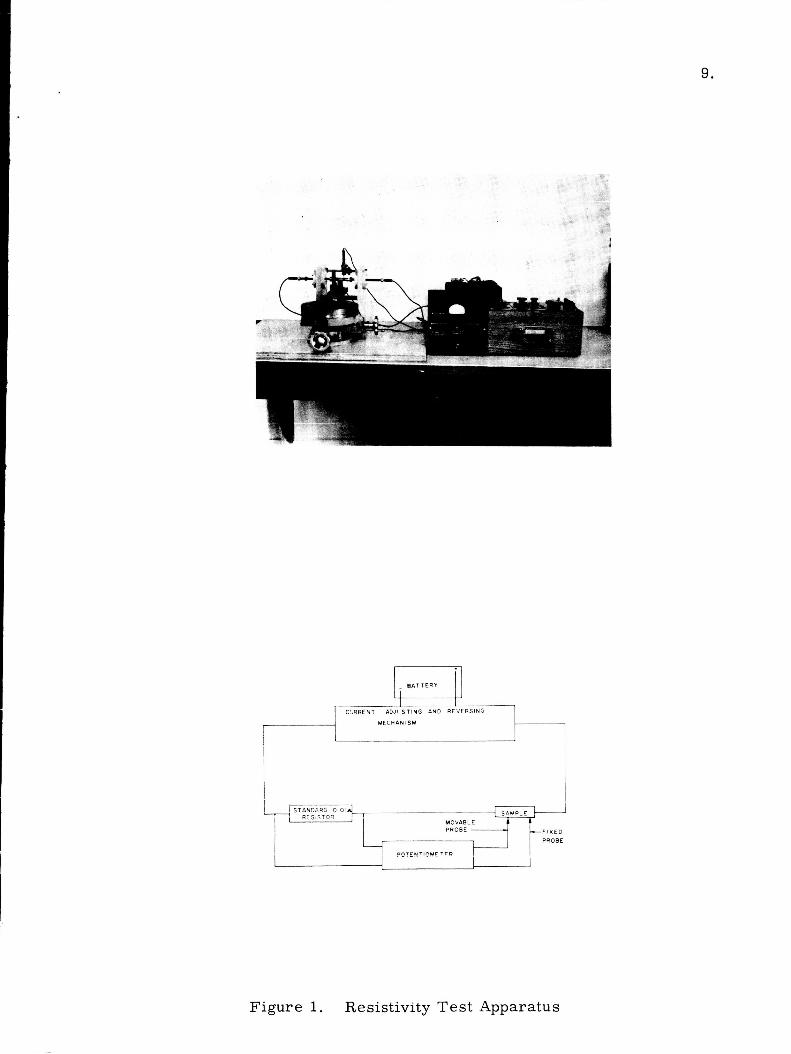
B. EsuiDment
Three i tems of special equipment were designed and manufactured for this program. electrical resistivity, Seebeck coefficient, and torque strength of bonded elements. A l l resistivity and Seebeck measurements were made with a Honeywell Model 2 7 3 3 precision potentiometer which could be read to 1 microvolt in the 0 - 11 millivolt range and 10 microvolts in the 11 - 1 1 0 millivolt range.
These were used for measurement of room temperature
These devices a r e shown schematically in Figures 1 through 3 .
A l l other operations were performed with standard laboratory equipment, some of which was modified specifically for this program. pressing of thermoelectric elements was performed in an inert atmosphere Plexiglas chamber. and load applied with a Carver Laboratory P r e s s .
F o r example, hot
Power was supplied by a 1 2 . 5 KVA Lepel induction unit
Wettability tes t s were carried out in a Lindberg tube furnace equipped with inconel muffle and purified argon atmosphere. deoxidized by passing over heated calcium chips and dried by successively passing through two dry ice - acetone cold t raps and a Drierite unit. This equipment is shown in Figure 4.
The tank argon was
Bonding was performed in the stainless steel and graphite fixture shown in Figure 5. at the other end permitted evacuation of the entire setup and subsequent back- filling with argon. Heating was accomplished by inserting the vycor tube into a furnace.
This was inserted in a vycor tube closed at one end. Fittings
Other equipment employed included conventional furnaces, balances and vacuum systems, et.c.
9.
BATTERY Ell MECHANISM
I
- F I X E D PROBE
Figure 1. Resistivity Test Apparatus

SAMPLE
Pt -1Pt Pt 13% R h 13% Rh
rfOT JUNCTION
17- , POTEN 1 IOME TER
Figure 2 . Seebeck Test Apparatus
~ ~~

11. I I .
K 0 v) Z W v)
W 3 0 a
0 - 0 a 0- I- o W \
, w 0 a z 3 LL
a
W
z J -
I- v) w t-
LL 0
Z
-I a. a

I 12.
W 3
w

Thermocouple
i
7
13.
Compression Rod
Lock Pin
Spring .-LccLL
-Graphite Alignment Sleeve
- Shoe
Braze
- PbTe
-Braze - Shoe
- Vycor Tube
FIGURE 5. THERMOELECTRIC BONDING APPARATUS

14. I
I .
I IV. PRELIMINARY BRAZE -- AND SHOE MATERIAL EVALUATION
The first phase of the laboratory program was concerned with the selection of several braze alloys, preliminary evaluation of these alloys , and the decision to continue work on several of these brazes . evaluation of shoe materials was similarly performed.
A preliminary
This preliminary evaluation consisted of wettability t e s t s in which the flow and adhesion of each selected bra.ze on p-PbTe and n-PbTe was deter- mined. were tes ted on each of the potential shoe materials.
Those brazes which gave some positive indication of wetting on PbTe
The following paragraphs describe the preparation of the PbTe thermo- I electr ic elements employed in these and subsequent tes t s , the braze and shoe
mater ia ls selected, and the procedures and resu l t s of the wettability tes t s . I
i
A. Preparation of Lead Telluride Elements -
1
I
Almost all the thermoelectric elements used in the course of this pro- The need to incorp- gram were fabricated from powders in our laboratory.
desirability of having elements made by a consistent process were the reasons for our decision to fabricate in-house.
orate additives in the elements for the poison effects study and the general
Lead telluride elements were manufactured by a hot-pressing technique. This process is described as fo l lnws weighed out. in a glass bottle and tumble mixed for one hour. was then loaded into a single action graphite die. punches were coated with high purity alumina to insure easy removal of the pressed pellet. tu re pr ior to use to eliminate volatiles that might contaminate the product.
The correct arnourzt of powder was If a poison additive w a s included the weighed powders w t ' r e pkecc!
The PbTe OT blended powder Faces of the top and bottom
New dies were baked out at or near the hot pressing tempera-
The die was placed into an inert atmosphere chamber which consisted of a nine inch cube of Plexiglas. coil, argon inlet and outlet, and a piston through which the load was applied. The chamber was then purged with argon, heat was applied through the 12 .5 Kw inductiwi iiiiit. and held fo r the requisite amount of time.
Lead throughs were available for an inductior,
The die w a s raised to temperature and the load was applied
Two sizes of PbTe elements were produced, 3 / 8 inch diameter by 5 / 8 inch high, and 1 / 2 inch diameter by 314 inch high. The smaller elements were manufactured for wettability tes t s only. were made on one-half inch diameter elements. PbTe pellets were hot pressed during this program. m e t e r s a r e described in Table 3. Hot pressing time w a s 15 minutes during ear ly runs and w a s reduced to about 5 minutes la te r in the program wiTh no measurable change in density or properties.
A l l other t e s t s and measurements Several hundred p- and n-
The manufacturing para-

M
a, P cd
4
E
Lo d
d't d't f-
Lo cv 4
co M \
aJ E P a c I
z U w B
cv 1
Lo d
0 CD f-
Lo cv +
aY M \
0 E P PI a
a
U W E
c\1 I
Lo d
I
Lo
co 03 f-
Lo Cil
d
cv \ d
0 E-l P !&
c I
z U m E
cv I
Lo d
I
Lo
0 CD c-
m cv d
cv \ d
0
P
a
E a
I
a
U w E
cv I
Lo
0 CD ct
m cv d
cv \ d
a, E c v1 P a a I
-- 6.4 M
I
U W F
15.
E -3
+ a 0

I 16.
A few, 112 inch diameter TEGS-3P, p-PbSnTe elements were also hot pressed during the latter part of this program. optimize pressing conditions for this material. employed in the manufacture of these pellets a r e also listed in Table 3.
No attempt was made to The hot pressing parameters
I
Hot pressed PbTe pellets appeared to be sound. Densities were in excess of 97 percent of theoretical.
and sintered elements. density.
Metallographic examination indicated I virtually no porosity compared with extensive porosity in 3M cold-pressed
The p-PbSnTe pellets did not achieve a s high a N o 3M produced p-PbSnTe elements were available for comparison.
The PbTe elements produced in our laboratory displayed thermoelectric properties quite comparable to those reported by 3M. Electrical resistivity values for several Hittman produced p- and n-type PbTe elements a r e shown in Table 4 and a r e compared herein with measurements made in o u r laboratory on 3M produced elements and with electrical resistivity values given ir. 3M technical l i terature. percent variation in resistivity claimed by 3M for their own products and a r e consistently lower than the 3M average. about 1 5 percent below the 3M values
These data for n-PbTe generally fall within the + 10
The p-PbTe resist ivit ies averaged
Figure 6 shows the values of Seebeck coefficient measured on p- and I n-PbTe elements produced at Mittman Associates and compares them to the t
values reported by 3M. l imits. It can be seen that the Hittman produced n-type elements fall un i - formly within these limits, while the p-type PbTe generally f a l l in the 3M limits with some deviation on the high side.
The dashed lines define the 10 percent deviation
B. Selection and Preparation of Braze Alloys
Prospective braze alloys were selected on the basis of the following cr i ter ia :
(1) Melting point below that of PbTe (917OC).
(2) Expectation that serious poisoning would not occur.
(3) Expected remelt temperature above device operating ieriipei-ature
Other desirable cr i ter ia such as wettability and compatible coefficient of thermal expansion could not be applied because of a lack of reliable data. On the above basis the materials listed in Table 5 were selected for prelim- inary evaluation a s braze materials. knownpoisons to PbTe, were selected for use a s controls to check our instru- mentation.
Those containing coppel- and silver,

1, I - - 1 7
Table 4
Room Temperature Electrical Resistivity
Source
of PbTe Elements Hot Pressed at Hittman Associates
Hittman Associates
Resistivity, microohm-inches
1 3 q
1 2 4 1 Hittman Associates
Hittman Associates
Hittman Associates
148 I ,,,I 140 average
Hittman Associates 157 I Hittman Associates 1351
3M TEGS-2P - - Tested at Hittman Associates 188
3M Literature -TEGS-2P 165
(b) n-PbTe
Hitt m an A s s oc iat e s
Hitkman Associates
Hittman Associates
Hi ttm an A s s ociat e s
Hittman Associates
3M TEGS-2N - - Tested at Hittman Associates
3M Literaiui-e ~ TEGS-2N
166
181
195
181
185
2 02
200
182 average

220
200
180
160
140
120
100
80
3 0
I

19,
Table 5
Potential Braze Alloys Selected for -- This Study
--
Alloy
SnT e
Bi2Te3
InSb
CdSb
InSe
InT e
SbZTe3 AuZn
5670 Ag - 4470 Sb
51% In - 59% Au 1
76 . 570 Sb - 23. 570 CU
79. 9% Sb - 20. 1% Zn
7070 Sb - 3070 Bi
Sn
Bi
Se
Sb In
c u
0 Type of Alloy Melting Point, C
Compound
Compound
Compound
Compound
Compound
Compound
Compound Compound
E ut ectic
Eutectic between AuIn and
Eutectic
Eutectic
Solid Solution
El em ent a1
Element a1
Elemental
Element a1 El eme nt a1 Elemental
A uIn2
7 90
585
530
456
660
6 96
6 2 2
725
485
494
526
505
430 2 32 n-1 L I I
2 17
631
157 1083

20.
Braze alloys were prepared by the following procedure. The compo- nents of the alloy or compound were carefully weighed out to the nearest mill igram and were placed in a vycor o r pyrex glass capsule. The capsule was pumped down by a mechanical vacuum pump, backfilled with argon and then pumped down again. A minimum of ten pumping, filling cycles were employed. Each alloy was taken above i ts melting temperature, removed from the furnace, agi- tated and reheated at least five t imes. The capsule was then air cooled to room temperature. Metallographic and visual examination showed that all the alloys were homogeneous and sound except for InSe which could not be successfully prepared in two t r ia ls . No further work was performed with this material .
Following the last pumpdown the capsule was sealed.
C. Selection of Shoe Materials
Samples of eleven prospective shoe materials were procured in sheet form for wettability tes t s with selected braze alloys. were selected so a s to cover a s many classes of material a s possible. Columbium and molybdenum, for example, a r e refractory metals, beryllium is a light metal, iron, nickel, and 304 stainless represent the conventional engineering materials, and Haynes 25, Rene' 41 and Multimet a r e examples of nickel and iron base superalloys. Both nonmagnetic and magnetic alloys were included. Table 2.
The shoe materials
The entire l ist of shoe materials was given previously in
A preliminary evaluation of braze and shoe materials was performed Those by checking the wettability of each of the braze materials on PbTe.
that appeared promising were tested on each of the potential shoe materials. The wettability of each of the shoe materials by PbTe was also checked. tes t s were carr ied out in the Lindberg furnace setup pictured schematically in Figure 4 above. -50 C or better.
The
The argon atmosphere was maintained at a dewpoint of
Tes ts of the wettability of PbTe by various braze materials were car r ied out in the Inoiiuw-iiig m x x ~ r . For each test wafers of n-PbTe and p-PbTe were placed on an alumina plate. A sample of the braze to be e v d - uated was placed on top of each wafer and the assembly w a s carefully inserted into the furnace. was then heated until signs of melting of the braze w e r e visually observed through a Plexiglas port.
The muffle w a s purged for at least one hour and the sample
The samples were examined visually and were then cut through the bond with a jeweler ' s s a w and mounted for metallographic examination. Table 6. shows the resul ts of these tests and identifies those braze materials chosen for further study.

Sn
Bi
Se
Sb
In
c u
273
27 1
217
6 3 1
157
1083
Table 6
Wettability of PbTe by Bra ie Materials
Chosen for Braze Braze Melting Max. Tzst Continued Mat e r ial Temp. OC Temp. C Results Evaluation
SnTe
Bi 'Te3 2
InSb
CdSb
InT e
Sb2Teg
AuZn
790
585
535
456
6 9 6
622
7'25
270
300
233
700
192
657
86 0
648
52 5
612
- A 7 l L f l
670
86 9
poor flow but good adherence
good flow and adherence
good flow and adherence
poor flow, good wetting
poor flow, no bond
entire sample had melted, the 500% Cu-PbTe eutectic temperature was exceeded
good flow, excellent wetting, some cracks and p o ~ e s , retest showed no pores
excellent flow and wet.ting, p0rt.s iii Bi 'Te3 adjacent to interface 2
good flow and wetking, cracks in PbTe
braze separated from n- PbTe before mounting; p-PbTe sample had two intermediate phases and poor flow
excell pnt flow and wetting, some pores and cracks in InT e
Good to exceiient flow and wetting, pores in p-PbTe adjacent to interface, signs of crackirg or separation in n-PbTe interface
no bond f w m e d
X
X
X
X
X
X
x
22.
Table 6 (Cont.)
Chosen for Braze Braze Mzlting Max. Tgst Continued Material Temp. C Temp. C Results Evaluation
56% Ag - 44% Sb
76 . 57'0 Sb - 23. 570 CU
79. 9% Sb - 20.170 Zn
48 5
494
526
505
430
666 extensive penetration X into PbTe, good flow, phase in interface
582 poor flow, poor bond
67 3 good flow and wetting
649 poor flow, two phases in interface
665 good flow and wetting, X f e w cracks in PbTe

2 3 .
Choice was made on the basis of test resul ts , However, program limitations made it necessary to remove from further consideration some materials that were of marginal interest. from each group, elements, intermetallic compounds, eutectics and solid solutions
A t least one mziterial w a s chosen
Wettability tes ts on shoe materials were carr ied out in a similar manner. and Carpenter No. 1 0 were obtained la ter and tested separately) were placed on the alumina plate m d the bra-ze to be evaluated was placed on each. Test and evaluation procedures were identical with those described above. resul ts of these tests a r e reported in Table 7 . PbTe on each shoe ma-terial a r e included in this table.
In this ease sheet samples of nine of the shoe materials (Magnil
The Results of wetting tes t s of
In no case was a flux used to aid wetting. Sample preparation consisted of abrasion to remove surface oxides followed by degreasing in acetone. The reported resul ts a r e indicative but a r e not conclusive evidence of the bonding that may be obtained by varying the cycle parameters. will be more readily attained with the iron, nickel and cobalt base alloys than with beryllium or the refractory metals.
It i s clear that bonding
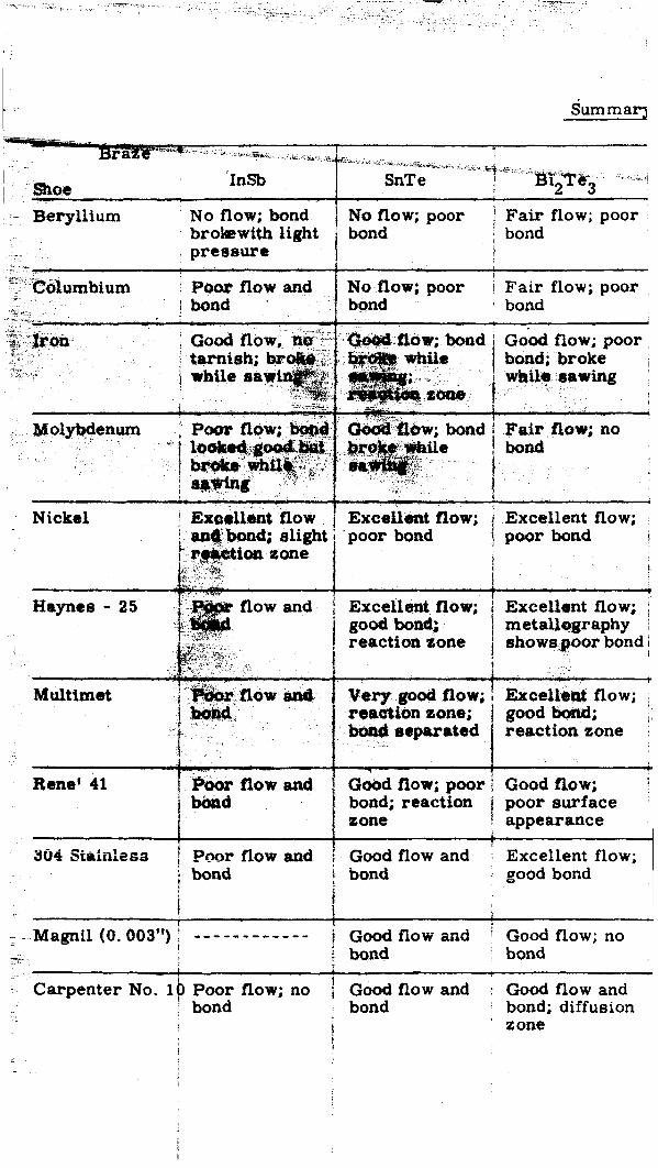
i u m m a q
Nickel
Hayncs - 25
Multimet
Renet 41
- - Magnil (0. 003")
Carpenter No. 1
-".
reaction zone
h , * * , t
h r flow and bbrrd bond; reaction 1 poor surface
Poor flow and 1 Good flow and bond
Good flow; poor \ Good flow;
sone ! appearance
!
I
1
Excellent flow; . .a uood bond j bond I
1
i Good flow and ' Good flow; no j bond bond
Poor flow: no ! Good flow and 1 Good flow and
- - - - - - - - - - - -
bond bond bond; diffusion ' zone
i
,

Table 7
of Wettability Test Results of Brazes on Shoe Materials
reaction zone; 1 Sb2Te3 cracked
L 1
boor flow and Bad reaction
bond
.I
- - - -- - - - - - - - - 1 - - - - - - - - - - - - -bond j
l Good flow and Good flow; - - - - - - - - - - - - - j Good flow and bond; InTe cracks in cracked interface I bond
!

24.
I
~ 1 39 flow or bond I No flow or bond I I i
I 1.
i bond
i
Vary god flow; cracking in PbTe phase

25.
V. POISONING EFFECTS STUDY -
Preparation of suitable element to shoe bonds in PbTe thermoelectric elements requires the satisfaction of two principal cr i ter ia . bond must be mechanically sound initially and must remain sound throughout the required lifetime. Second, the diffusion of material from the shoe and/or braze into the thermoelement must not deleteriously affect the thermoelectric properties of the material. thermoelectric output declines a s a result of diffusion from the bond into the element so
Fi r s t , the
The sturdiest bond wi l l be unsatisfactory if the
Therefore, a s a further screening tool, t es t s were undertaken to determine the effect of small additions of prospective braze and shoe materials on the thermoelectric properties of PbTe. Two ser ies of experiments were performed, one in which only the a s hot-pressoed properties were measured and a second in which the effect of t ime at 538 C ( l O O O ° F ) was also considered. These experiments were in the nature of accelerated tes ts . prescribed amount of foreign additive was dispersed in the PbTe powder prior to hot pressing i n o rder to simulate a condition analogous to one that might result from diffcsion mechanisms after hundreds or thousands of hours of operation at elevated temperatures,
In each case the
The first. test se r ies was performed a s follows. One n-PbTe and one p-PbTe sample containing each contaminant was prepared by the standard hot pressing technique for ofie-half inch diameter samples described in Chapter IV. Generally one percent by weight of the additive the only exceptions being in the case of nickel where a few samples containing smaiier amourits ;.,ere p r e p r e d . run and good qualitative agreemerrt was obtained.
was employed,
In several cases duplicate samples were
Eighteen additives weye employed in this study:
SnT e 70 w/o Sb - 30 w/o Bi F e SnTe - 1 w/o Ti
SnTe - 1 w/o V Bi2Te 3 InTe
SbZTe3
InSb
Sn
Bi
Mo
Cb
347 ss Carpenter No. 10
Generally, the specimens containing additives to the easily hot pressed n-PbTe could be fabricated about a s well as the unpoisoned samples. which is more difficult to fabricate, presented some p i -cb leas when samples containing some of the braze materials were required. were frequently required to obtain a sound element. On the other hand certain additives, notably molybdenum and columbium, resulted in p-PbTe elements that were excellent in appearance and that appeared substantially stronger than the ordinary p-type material ~ Although development of improved lead te l lwide mater ia ls was not within the scope of the work, the above observations may warrant further investig- t ions '
P-PbTe,
Several pressings

26.
Resistivity and Seebeck coefficient measurements were made on each sample using the equipment described previously. in Table 8. measurements made on each sample plus the calculated deviation from mean values for unpoisoned p- and n-PbTe.
The resul ts a r e given In this table a r e listed the Seebeck and electrical resistivity
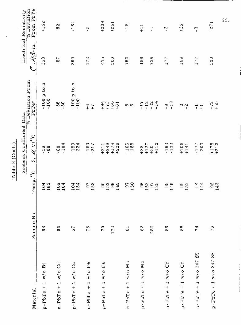
It i s cbvious from these results that SnTe and the two modified SnTe materials have substantially l e s s deleterious effect on PbTe than any of the other brazes studied. F o r these alloys an increase in the resistivity of p- PbTe of 40 - 140 percent with 1 w / o SnTe is the largest degradation observed. The additions of Ti and V to the SnTe braze reported in Table 8 were made primarily to improve bond strength as discussed in Chapter VI. However, it can be noted that, the braze with these additions also shows l e s s degradation of resistivit.y in p-legs than straight SnTe. effects were inversely proportional to the melting temperature of the additive. That is , the smallest property changes occurred with molybdenum and colum- bium additives , greater changes were observed with iron, nickel, and stainless steel, and the most drastic effects occurred when copper was added.
Of the shoe materials the observed
In all cases the effects were significantly greater in p-PbTe than in n-PbTe. This is in general agreement with other studies of PbTe.
One sample of p-PbTe to which was added 1 / 1 0 w/o Ni showed no poisoning effect, indicating that the threshhold i s between 1/10 and 1 weight percent for that additive.
Subsequent to the electrical property measurements each pellet was cut and mounted so that metallographic examination could be performed of t rznsverse and !sngitvdinal sections. could be seen present a s discrete second phases uIiifor;;l?y dispersed in a lead telluride mat.rix. Lead tellurides containing tin telluride appeared to be largely single phase and in the case of the BiZTegJ InSb and Sn there were signs of at least partial
solution into the lead telluride matrix.
A l l of the potential shoe materials
This was generally t rue of the braze additives also.
The above observations led to the probability that further poisoning effects might be observed if PbTe containing additives were held at elevated temperatures in order to allow further solutioning of the additive. For this reason several samples containing one percent additions of SnTe, SnTe - 1 wAo Ti , S n , Fe, and Carpenter No. 10 alloy were prepared and tested at 538 C (1000°F) for t imes cp to 6Q0 h o u r s . ples were tested at the same time.
Several unpoisoned control sam-
The tes t procedure was as follows. The Seebeck coefficient and elec- t r ical resistivity of each sample was measured aftcr hot pressing. sample was then placed in an individual vycor capsule which was evacuated and backfilled with argon several times and then sealed under one-half atmosphere of argon. furnace, heated to the tes t temperature and held for the desired ler!gth of time. Samples were removed and properties remeasured after intervals of about 100, 300, 400 and 600 hours. After one or two cycles all the p-PbTe materials
Each
The sealed vycor capsules were then placed in a

0 0 c- + d
0 c- m hl
c 0
a 00 0 0
+
4l-l I I
4 m loa I I
TPa o m 4 4
0 0 0 * 0 m c- + 4-
C D c - 4 co c - m M * M u 3 m I + + +
m * l-l +
cr) * M
CD m +
co l-l m
hl M I
M hl l-l
corn WCD I I
c o r n mc- I I
CDm OCD 4l-l
M I
CD
4
* + m I
m f- 4
cd 0
k 0 a,
.+ c,
4 w m 0 * m l - l m co m 0 m C D m f- 0 c o c o c-
0 l-l
0 co m CD
a, E P a +l 0
k a,
a, c c .+ k cdo k a a, 0
5 B e
c,
m h l C D c o
m m oc- 4 4
E 0 k
cum *o l-lm
m m A 4 + +
cu c o m m 4 + + I +
m m m * I I I +
+ + a 5 c, c a, -+ 0
+l a, tH" h
0.
CDc-cohl m m m m c u 4 l - l l - l + + + +
v 0 u oco 4 c u cum I I
mCD m o hl- + +
c,
c 0 m a
o m 4l-l
m m m h l o m m m 4 4 rl
M a m c -
d + C L
M a, k
DJ
5
M ?? a, E
a
E s
a, E QJ
2 cn 0 \
3 d
+ a, E P pc c I
a,
2 tn 0 1
3 4
+
a E c 0 H
1
3 r(
+ a, H P P(
si 1
a,
c 0
E-l H
1
B 4
+
hl P tn
cu P tn
0 \
B 4
+ a, E P a c
I
0 \
3 l-l
+ a, E P a a l
0 \
0 1
3 B d d
+ + a, a,
0
B 4
+ a, ' P a a l
a,
P E a
a, E P a
H a a ' P P E e a I I r: a I
cl I a I
a

28. 0 0 0 0
a m d l m 0 0 rl CD +
0 0 co * +
0 0 co co
" 0 0 3 "co + +
m m mco m m I I
da o m 4 "
co M
P m ho 4 0
3
I + a, E P a c
I
\
I "
I
N m I
b b M * I
* d m rn @2 4 " 4 I + + + t t + +
0 * co 0 t- d co
f- co
c 0
a 0 0 0 0
-c,
+ d I I
M In" a" I I
a m O C D " 4
O M * * I +
O m m *
I I
mc\1 " N + +
mco d m d" t f
m o cow "
N * + +
a c o c-a " d I i
coco c o r n "
cot - + +
c o r n Ocr,
+ + " 4
y? 1 0
C O N "
CDmmdl c o d N f - " N " " + + + +
M f-t- m d + +
m m 4 03"
I I
coco t-"
4
M M "t- d"
cn o m N m c o c o CD
l
a, I
a, l
a, .,-4
F? P m 0 \
3 " +
E c tn
2 cn '-/
P m c 'J1 0
"-- 3 " + a,
P b a
i i cn -- 0 .g --. B O
---. '0 5 3 0 " 3 + "
\
aJ
0 \
3 4
+ aJ b P a
0 \
3 0 \
3 4
+ a,
E-c P a c I
--. " 3 + d a, E P a c I
\
" 3 + " a, b P a a I
4
+ al E P a a I
a, E P a
a,
P E a
5 a I c I a a a
29. d
m L- m Ccl m + 1 +
e CD 4 +
al (D m
c 0
a 00 0 0
c,
rl4 I I
O* mcv r l c v I I
*e OLo drl
c\1 m I
t- a3
(DO m m I I
* 0 0 a 3 4 I I
(D* OCD drl
cv m C D 0 m a l L- L- t - 0 m m m t- d e m rl T - i d rl
al t- 0 co t- cv d T-i m
crc
e m c o d alr-CDCD + + + + O N
I
c o d O W d d + +
a l m a m
4
T-ialala d w b m c v c v d m + + + +
I . - 0 c o c v o r l c o d c o d + + + +
* t- (D CD
Cr) o m d m o CD t- c - c - co c o c o co
d cv co d+ m a3 t- t-
cn cn m m c- v m 0 1
3 rl
+ a, E E c
s s 5 u 5 a, u h a,
0 h
3 \
P u L u 0
3 --- d
+ a)
E E a
0 \
3 rl
+ a, E P PI c I
0 \
3 d
+ rl
l- a)
E E
@ E a a P P
I I a c i a
1 I
c a c

0 4 I
M ED 4
CDW I I
N O c -m 4 4 I I
mcu O m 4 4
c- t- 4
0 4
i k a, Oc, \e
4 h cd
3:
+ u Q)
E-r P a c I
M I
CD c- 4
4 4 w I +
F E D m o 4 c c J I I
CnM corn
4
0 c- cu
.+ z
s 0 \
cu \ 4
+ a, E P a c I
c- +
* 0, 4
cum + +
MCQ coo -4m I I
w m m w
4
co c-
5 0 \
3 4
+ a, E P a c I
0 0 0 m +
m c- 0 c-
0 0 c\1 CD +
0 CD co co
0 0 d+ IC +
0 t- W c-
0 0 * m t
0 * CD
M m m t - c . l c n o M m d + c M m v * m m + + + + + + + +
4 4
-t + a, a,
E P
P P a a a a I l
a u, u 3 a 0 k a
30.
a r: cd a k 0 %I
m "+
.+ t- a ..-I
3 a, -0
3 m m .+ c 0 .4 c'
.?I cd ? aJ a
6i ..

31
I with and without additives were found to have high electrical resistivity. Sev- e ra l broke during test and the others had visible cracks present. no useful data were obtained.
Therefore,
The data obtained on hot pressed n-PbTe and n-PbTe containing several additives a r e reported in Table 9, lead telluride indicate i ts properties to be within the normally expected ten percent variation. degradation after 600 hours at temperature. The resul ts for SnTe indicate little change over the 600 hour test period. SnTe - Ti additive after the 113 hour test.
Measurements performed on unpoisoned
Samples containing additions of tin and iron indicate some
Similar resul ts a r e seen for
These limited resul ts support the selection of SnTe and modified SnTe They also point up the need for a s superior braze alloys for lead telluride.
improved p-type lead telluride materials.
A s a result of the need for better p-type material , a supply of TEG-3P PbSnTe powder was obtained from 3M Company. were prepared from this material, but because of the non-optimum fabrication conditions employed, the resul ts were ambiguous. is needed.
A few additive test samples
Further study in this a r ea

Table 9
o Effect of Agifig ab 538 C on the Thermoelectric Propert ies of - n- PbT'e Corztjining - Additives
Percent Deviation From Average PbTe Values Time at 538OC
Sample No, H o u r s Seebeck Resistivity ---- Material
n-PbTe 185
n-PbTe 1 9 0
n-PbTe + 1 w i o SnTe 196
n-PbTe + 1 w / o Sn 175
n- PbTe + 1 w/ c { SrrT e-Tii 2 4 3
n-PbTe + 1 wlo F e 1 7 3
0 + 3 - 9 96 -3 -2 322 - 7 +4
0 +1 -1 96 0 +7 322 0 +7
0 - 1 2 +4 111 -6 +33( ? ) 443 -15 +5 599 -8 +7
0 -6 - 3 111 - 4 +1 443 - 16 -8 599 -17 +7
0 +2 +17 1 1 3 -2 +12
0 +2 - 5 111 -2 +2 4 4 3 -19 - 1 0 599 - 9 - 1 3

3 3 ,
1 - VI. BOND PREPARATION AND EVALUATION
The resu l t s of the screening t e s t s described in the preceeding chapters
Tin telluride was the braze chosen were applied to the selection of braze and shoe systems for evaluation in the fo rm of bonded thermoelectric elements. for detailed evaluation. ducing reliable bonds, the titanium and vanadium additions to the braze material were developed.
When some difficulties were encountered in pro-
The shoe material chosen for detailed evaluation was iron. Some bonds were made with nickel, Mul.timet and Maynes-25 shoes, but t ime limitations prevented extensive study of these metals. Carpenter No. 10 alloy was also selected for study, but could not be obtained in the form of suitable bar stock.
Bond specimens in all cases consisted of one-half inch diameter elements and shoes. elements was one inch. testing the thermoelectric elements, 1 / 4 inch shoes, primarily for corxenience in mounting for metallographic examba t ion.
Element length was 5 / 8 t o 3 / 4 inch. Shoe length in most bonded This length was selected for convenience in torque
A few bonds were made with 1 / 8 to I
A. Bond PreDaration
A few ear ly bonding experiments were performed by placing the shoes, braz,e and thermoelements into a graphite h0.r pressing die and applying about one tsi pr-essi~ire at 7’90 C . SnTe braze, in the form of powder, was employed. The resu l t s were generally unsatzsfactorv. Subsequently, all bonds were made in the fixture pictured in Figure 5 (Chapter i i I j . bond runs were made with the SnTe braze in the form of powder, cold pressed disks and cold pressed disks sintered in hydrogen or argon atmosphere. The most consistent satisfactory resu l t s were obtained when pressed and sintered braze disks were used. phere
0
Frdiminary
Little differeace resulted f rom the choice of atmos-
The standard procedure employed in the preparation of braze wafers was a s follows. pressed into wafers of 1 / 4 o r 3 /8 inch diameter by approximately 0. 010 inch thick. The wafers, separated by alumina sand. were placed into a vycor capsule which w a s evacuated ani! backfilled with argon several t imes and finally sealed under one-half atmosihere of aygon, placed in a furnace and held at 600 C for about one hour. were then placed in 1iisthaEnl for storage until used.
Melted SnTe was ground to powder, The fresh powder was
‘i’he sealcd capsule was & - The sintered wafers
Similarly, several techniques fa r the preparation of the mating surfaces on the shoe and element were investigated, f rom these experiments,
Three conclusions quickly emerged For the attainment of sound bonds:
(1) It is necessary t o maintain the mating surfaces parallel to one another.

34.
(2 ) Absolute cleanliness is required,
(3) Proper surface preparation is required.
The optimum element and shoe prep as at ion^ methods developed during this program were as follows:
(1) Shoes: This procedure was followed for iron, riickel and alloy shoes.
The machined shoe was polished successively on 240, 320, 400, and 600 grit paper and then firiished on polishing wheels with No. 3 universal diamond paste followed by 1 micron alumina. The shoe was then scrubbed in hot soapy water, rinsed in clear water, wiped with acetone, r insed with methanol and stored in methanol until used.
p-PbTe:
Hot pressed p-type elements normally had small chips missing at the= c o ~ n e r s . flat on 180 grit paper u r t i l a complete c i rcular cross section was achieved. each end, Followirg this operation the procedure was ident- ical to that used with the shoe mcterials.
T h e elements were ground
Almost 1 / 16 inch was usually removed from
( 3 ) n-PbTe:
About 1 i 3 2 inch was ground from each end of the ele- ments. the elements in one direction across 180 grit paper. elements were then clemed in soapy water, r insed with water, wiped with aceTwe, rinsed with methanol and stored in methanol.
Paral le l scu i -? mark-s were then made by drawing The
Elements were bonded in the following manner, The shoes, element and braze wafers were removed from the methanol in which they were stored m d dried with clean Kimwipes. Differences in flow character is t ics required use of 1 / 4 inch diameter wafers with p-PbTe and 3 / 8 ‘nch diameter w a f e r s with n-PbTe. The components w e r e assembled and placed in a graphite alignment sleeve which was in turn inserted intc the s teel brazing jig (See Figure 5, Chapter 111). Light pressure w a s z ~ p l i e d through a sprivg to hold the assem- bly in position. The assembly was irzcrted into a large vycor tshe whieh was sealed, evacuated and purged with argon. A small a rgon flow was maintained. The vycor tube w a s inserted into a furnace. The temperature was ra i sed to 790° - 800 C, held for five minutes ar,d a l lowed to f u rnace cool to about 600 C.
0 0
The assembly wa8 then placed into a brick ho1din.g chamber which allowed it to slowly cool to 200 C at which time i t was opened and the assembly removed.

35.
B. Bond Evaluation
i Low resistance bonds were consistently produced by this process. However, the bonds were often quite weak an.d separated under light pressure. The use of one inch long shoes tended to magnify this lack of strength since the shoes were easily grasped some distance from the elements.
In order to increase bond strength elements brazed with SnTe modified by the addition of one weight percent titanium were prepared by the techniques described above. SnTe brazed elements, almost always under lOOM&
, Bond resistance was comparable to those obtained with
Limited metallographic study has been made of bonded PbTe elements. The brittle nature of the material makes cutting and mounting difficult. Polishing and etching also present problems which a r e just beginning to be overcome. Figures 7a and 7b a r e photomicrographs of good bond a reas in p-type and n-type PbTe respectively. and the braze SnTe-Ti. in the n-PbTe sample, but absent in the p-material , a r e required to further define this anomoly.
In each case the shoe material is iron A diffusion zone, about 0. 005 inches wide is present
More detailed studies
A numbgr of bonded elements were torque tested at room temperature, The resul ts 315' and 540 C in the device pictured in Figure 3 (Chapter 111).
of these tes t s a r e given in Table 10. for this tes t broke during handling prior to testing. Greater success was obtained with specimens brazed with SnTe-Ti. clearly seen that the torque strength of n-PbTe elements i s substantially greater. than that of D-PbTe. Although the data is limited it appears that bonds made with SnTe-Ti may be s i iongzr thgn those made with pure SnTe braze. It also appears that there is little, i f any, effect of temperature.
About one-half of the elements prepared
F rom Table 10 it can be
The single tes t element made with p-PbTe - 1 wlo Mo was the strongest, p-element tested at room temperature again indicating that further study of this material is warranted.
Examination of the fractured elements showed that the mode of failure was different in p-type and n-type materials. The p-PbTe almost always fractured in the thermoelectric material near the bond interface while the n-elements fractured at the bond. However, a chip often was removed from me 2 cle9-ents and a crack along the surface at an angle near but l e s s than 45 was usually observed. l h e s e effects a r e discussed in detail in the chapter on s t r e s s analysis f ollo wing.
Several specimens, also bonded with SnTe-Ti braze, were held at 538OC
Two p-elements ai?d
0 0 ,
for 113 hours and then torque tested. that no appreciable change resulted f rom this treatment, two n-elements broke after the thermal treatment, but before strength tes t s could be made. Results of these tests, which a r e reported in Table 11, were comparable to previous measurements. Fracture patterns were identical to those observed on samples not exposed to any tbprmal tre&tment. There was , however, a substantial increase in fracture strength of n-PbTe thermoelements. No such change was observed in p-PbTe. This is consistent with the conclusion, discussed in the following chapter, that p-PbTe of this diameter is cracked as a resul t of s t r e s ses resulting from the bonding process itself.
Bond resistance measurements showed

36.
PbTe
PbTe
D
f
a) p-PbTe unetched 3 OOX
F e
F e
b) n-PbTe u n e t c h e d 300X
Figure 7. PbTe Bonded to Iron Shoes wi th SnTe-Ti Braze

3 7 .
m + c ; a,
5-i 0
k 0 a, a,
.+ +
4
8 k a, c a,
k 5
a,
a cd a, J a a,
W c 0
c 0 [II
5 m
E
2 4 4
E
a
4 d
2
$
+ m a, E
0 k 0 E
a a ha c c?l c o o c o amom a,a,a,a, k a a a d A A 2 o o c o $ 0 0 0 0 0 0 0 + k k k ~ u a u ~ a a a
o o o m o o m c - r l l - l m m d d d
m o a 0 N c n * O mm*(cD
c o r n * m m m
0 0 * * m m
0 0
0 . . d o
aa, E b c c m m
aa, E E P P &PI a a I I
C D O mcn
u3lnmln m m m m
l n c n l n l n mmcIJm
0 m
0 0 0 - 0
0 . o m m w m 4
d
cn 0 I do
+ 2 a,a,a,a, b E E b P P P P LPIPIPI c e d e I I I I
a , a a a )
P P P P
a a a a
E E F E P I P I & & I I I I I I I I
a a a a
c-comm c o c o c n d
d

u 0 co m Lo
+-' cd m
M d d
k a,
2 W a, rn a, c,
E m c a, c,
a cd
2 a il a 5 a
0 0 co
m * 0 m ..)
0 d 4
.., N cu
.+ E a, E c v1
a, E P a c I
co r-l 4
0 0 P- rl
co * co * ..,
2 U
.., 0 m
s % a,
v1
a,
5 a c I
m N rl
0 Lo ED r-l
* -$
0 ..,
m
0 ..,
.d
E
E a,
c v1
a, I3 P & c I
c13 N d
38.
0 0 0 0 co Lo 4
N cu * c- Lo Lo M in .., ._ I
Lo 0 * * .* . * 0 f-
M
i; ,+ E l I a, a, E c cn 2 cn
a,
P
c
E PI I
co cu r-l
d * m c u d d

39.
VII. STRESS ANALYSIS
In this section we shall consider that the thermoelectric element is a brittle material and that, therefore, its failure cri terion is that it f ractures when the maximum principal s t r e s s reaches a limit, namely, the fracture s t ress . circular cylinder with i t s length approximately twice i t s diameter. bonded to a shoe at each end. thermoelement and a r e much stronger than the element so that yielding o r fracture of the shoes need not be considered.
We shall assume that the thermoelement is a right It i s
The shoes have the same dimensions a s the
Three separate s t r e s s patterns can be identified. In general, two of these patterns may occur simultaneously, but not three. a r e , f i rs t , that caused by the axial temperature gradient in the element when it is operating, second, that caused by mechanical constraints imposed on the element by the shoe, and third, that created by the torque tes t used in this program. the second two a r e present during the torque test . will now be discussed in turn.
The patterns
The f i rs t two a r e present during normal operation, and These s t r e s s patterns
A . Thermal Gradient S t ress Pattern
Let u s f i rs t assume that the Seebeck coefficient, thermal conductivity, and electrical resistivity for the element a r e all constant with temperature, that radial heat flux is zero, and that heat i s put into and removed from the e lemen t hy radiation so that it is f ree from all external surface forces o r constraints. exists in the axial direction only and it is a l inear gradient. The elexent wil l assume the shape shown in Figure 8a and it will be f ree of all s t resses , normal and shear . At f i rs t it may appear that shear s t resses must exist because of the change in shape. The new shape is that defined by two con- centric spheres and a right circular cone with i t s apex at the center of the spheres. spherical coordinates but remain mutually perpendicular at all points, indi- cating that shear i s absent. change in l inear dimension along the temperature gradient and, a s long a s this gradient i s l inear, occurs without internal constraint.
Under these condiiims the temperature gradient in the element
The cylindrical coordinates of the original shape have now become
The change in shape is due solely to the varying
Consideration of the geometry of Figure 8a leads in a straightforward manner to the following equations for the distortion of iiie element:

I .
I
\ \ \ I
1 r
- - -e .original shape at T 0
final shape underAT, T2>T S T - 1 0
Figure 8a
element L-
I 1 t
I I
I
axial stress
Figure 8b
Thermal Gradient Stress Patterns

41.
8 . where OC is the coefficient of linear thermal expansion and the other t e rms a r e identified in Figure 8a.
In order to investigate the s t r e s ses occurring in a bonded element due to this effect alone, let u s assume that the element i s bonded at the hot end to a shoe having the same coefficient of thermal expansion as the element, a very high thermal conductivity, and having a large mass and a high Youngs Modulus. that i t s base is forced to become plane but it will not be constrained radially. The bonded element i s shown in Figure 8b, which also indicates the distribu- tion of axial s t r e s s at the bond plane. the major ones present. ment at the centerline and tensile s t resses a t the surface. the element from the shoe, these s t resses eventually cancel each other with load transfer occurring through shearing s t resses .
Under these conditions the element wil l be constrained axially so
It i s apparent that these s t r e s ses a r e The shoe applies compressive s t r e s ses to the ele-
Proceeding into
It is interesting to note that if a second shoe is bonded to the colder end, the axial forces will be reversed in sign, i. e. , tensile on the center- line and compressive at the surface. If the element were quite short these axial s t r e s ses would tend to cancel each other but the associated shear s t r e s ses would be additive. drical elements wil l conform to the shoe by axial extensions while short wafer -like elements will conform by bending.
This is indicative of the fact that long cylin-
A complete s t r e s s analysis has not been performed but an approximate solution for the maximum axial s t r e s s has been obtained. axial displacement at the surface is:
The maximum
2
+ = A p 3 / N e,., 2 FA , (3 )
If one assumes that the axial s t r e s ses a r e cancelled length the maximumstress , which we shall call Cgrad , for gradient s t r e s s . has the following value:
in l / n of the element
This s t r e s s has a value of 2250 psi under the foiiowing prcperty values and dimensional assumptions:
6
o ( = 18 x 10
E - - 2 x 10 psi -6 oC-l
0. 5 inch - - DO
- - 1. 0 inch - - 6OO0C
LO
T 2

42.
It is thus apparent that under the postulated conditions the gradient s t r e s s may approach the breaking s t r e s s of the element. be l e s s severe due to deformation of the shoe.
The actual case will
Two additional sources of thermal s t r e s s exist in an operating thermo- F i r s t , the figure couple but they a r e probably smaller than the above effect.
of meri t of PbTe peaks rather sharply over the usual operating temperature range and second, radial heat flow is not zero. Both effects introduce non- linearities into the thermal gradient and therefore introduce additional thermal s t r e s ses .
B. Shoe Constraint Stress Pattern --
We wil l now consider the s t r e s ses that a r i s e because of the difference in thermal expansion between the element and the shoe. bond to be made by brazing, it i s apparent that below the brazing temper- a ture the component having the higher coefficient of expansion will be in tension and that the s t r e s s level wil l continuously increase a s the bond temp- e ra ture is lowered. Thus, in the normal functioning of a PbTe-Fe thermo- couple, the element is in tension and the s t r e s ses a r e most severe at room temperature, relaxing appreciably a s the bond is heated back toward the brazing temperature. f racture s t r e s s it would not be si lb jer t to fatigue. on the f i r s t application of maximum s t r e s s , it would survive a!! subsequent applications of the same s t ress . probably represents a useful approximation over a limited number of cycles.
If we consider the
If a brittle material were perfectly elastic up to i t s Thus, i f it did not fracture
This i s not strictly t rue for PbTe but
We wil l consider the case of an element formed by brazing together at TB an element and a shoe each of which have a length to diameter ratio
of 2 . 0 . diameter at TB. The joint is formed and the bonded element is allowed to
cool to some temperature, T . We shall consider only one end of the element and we shall not identify the shoe and the element, referr ing only to com- ponent #1 a s having tile larger coefficient of expansion and to component #2 a s having the smaller . is #1 or #2 . The s t r e s s pattern ir, and near the joint is very complex and depends to an important extent on the properties of the braze material. type are more readily investigated by experimental methods than by analysis, Nevertheless, appreciable information can be obtained short of a complete analytical solution.
The shoe and the element a re formed so that they will have the same
The resul ts a r e thus applicable vðer the element Conditions at temperature T a r e indicated in Figure 9a.
Problems of this
The process by which the load is t ransferred from Side 1 to Side 2 Figures 9b and 9c a r e through the braze is at the heart of the problem.

43.
Side 1 Side 2 unstrained radii at TB, brazing temperature
- - '1 T
- - radius side 2, unstrained at T '2T r - - radius of bond, strained, at T
- - rO
radius side 1, unstrained at T, T 4 TB
Figure 9a
Figure 9b Figure 9c
Tensile Braze Joint Shear Braze Joint

44.
presented to clarify the process. In Figure 9b Side 2 has been enlarged and extended around Side 1 and the braze is confined to the periphery, neglecting for the moment, the problem of heat t ransfer . Under these conditions, the s t r e s s pattern in Side 1 is relatively simple. Within the c ros s hatched a rea the radial and tangential s t r e s ses tend to be equal and constant and shear to be zero, modified by the effect of the balance of the cylinder. The use of a braze joint loaded in shear , as indicated in Figure 9c, may be a structural simplification, but it is a very imperfect substitute for the other construction when the complexity of the resulting s t r e s ses is considered. formly and the biaxial s t r e s s pattern develops only gradually a s the loads are t ransferred into Side 1 by shear s t resses . braze is non-uniform. the bond only by yielding of the braze at the periphery. braze falls toward zero from the periphery inward and in many cases prob- ably reaches zero. gradual development of the zone of biaxial tension which is uniform in the other case. If the braze did not possess sufficient ductilityto yield at i t s periphery, thus distributing the load over a la rger area it would inevitably fail. The zone in Figure 9c in which the biaxial tension condition is devel- oping is subjected to shear s t resses . s t r e s s pattern is controlled by the manner in which the braze joint adjusts to the load and is , in general, not readily calculable.
Side 2 is now poorly located to load Side 1 uni-
The shear s t r e s s in the
The load in the The load is distributed over an annular region of
The cross-hatched zone in Figure 9c indicates the
The detailed nature of this local
In order to obtain a feeling for the general range of s t r e s ses involved, we will assume a condition of plane s t r e s s in the Figure 9b situation. This leads to the following resul ts for r, the radius of the bonded inter- face, and for bshoe, the maximum tensile s t r e s s caused by shoe constraint.
where, with subscripts 1 or 2 ,
o ( = : l inear coefficient of thermal expansion E - Young’s modulus
v = Poisson’s ra t io

45.
A value of dshoe has been calculated for a representative set of
values. It w a s found to be 17,700 psi when:
RO
=1 -2
*2
Y VZ TB T
0. 25 inch
18 x 10
10 x 10 6 2 x 10 psi
3 0 x 10 psi
0 .20 0. 28
7OO0C
-6 o C - l
-6 oC-l
6
ooc
The fact that dshoe i s appreciably greater than $rad implies that
shoe constraint effects a r e more serious than those due to thermal gradients. The value of 17,700 psi is well above the fracture strength of PbTe. discrepancy can be explained only in part by the simplified model used be- cause even in the situation of Figure 9c, the s t r e s s should closely approxi- mate the simpler case along and near the axis. the ear l ie r stages of cooling may reduce the s t r e s ses somewhat but this is not a complete explanation since in Equation (6) the relation between 6 a n d A T is close to linear and A T would have to be reduced to 2OO0C or l e s s
I-.-inu down to measured strength levels of PbTe. The explanation LO U L L A A b
probably does lie in the braze behavior however. 9c, if the braze flows sufficiently to permit significant offsetting of Side i from Side 2 , the s t resses wil l be greatly reduced. elastic elongation of the PbTe r a d i u s is only 0.0016 inch, the total s t ra in could be relieved by offsetting without being particularly noticeable.
The
Flow of the braze during
G h " e In the situation of Figure
Since the total calculated
It should be mentioned that there is a small axial s t r e s s component present as well. surface a r e elongated somewhat relative to those at the centerline. This will result in an axial s t r e s s component, tensile at the surface and com- pressive at the centerline. radiai-ianger?tizl s t r e s ses previously discussed.
A s can be noted in Figure 9a, the axial f ibers at the
These s t resses wil l be much smaller than the
The biaxial s t r e s s pattern will cause a brittle material to fracture in a s e r i e s of cracks originating at or near the bond and extending into the brit t le leg in planes parallel to the axis but randomly located around the axis. The cracks wil l tend to stop when they have progressed out of the highly s t ressed region. Their orientation is not such a s to cause ready separation of the joint, o r even to interfere markedly with electrical and thermal conductivity parallel to the axis.

. 46. I
C. Torsional Stress Pattern
In order to investigate the behavior of bonded joints further, a se r i e s of torsional tes t s were performed. and well known and is shown in Figure 10. It consists of a state of pure shear on all cylindrical surfaces falling from a maximum on the surface to zero at the centerline. The s t r e s s pattern i s constant as a function of axial displacement. Its value i s :
The torsional s t r e s s pattern is simple
Brittle maberials characteristically fracture in torsion under the action of q * i n a 45 helical pattern.
centration, the location of the initial fracture si te should be random along the cylindrical surface. two bonded shoes, the torque s t r e s s pattern i s complicated by shoe constraint s t r e s ses at the ends and fracture can be expected to initiate in the thermoele- ment adjacent to the bond.
If the end loads a r e applied without s t r e s s con
In the present case, when M is applied through
D. Experimental Program
A se r i e s of torque tes t s were performed on p- and n-elements bonded at each end to iron shoes. The braze in each caBe was SnTe or T i modified SnTe and the brazing temperature was 790 - 800 C. inch in diameter. Tests were run at room tempeYatare, 315 C, and 540 C. Results a r e tabulated in Tables 1 0 and 11 in Chapter VI. f rom the data f i r s t , that temperature does not exert a strong influence in this range and second, that the n-elements a r e characteristically about two to three t imes as s t rongas thep-elements,failingat 1100-1300 psi while the p-elements fail at 380
One further highly significant observation can be made from the samples and is indicated in Figure 11, a photograph of characterist ic frac- tu res of p- and n-elements andFigure 12 which shows the helical crack pattern in an n-PbTe element which did not break. characteristically resulted in the creation of a significant number of loose shards with a pnrtion of the element still attached to the shoe. surface a s revealed by the remnants adiiei-izg tc! the shoe was generally symetrical with the axis. inspection to represent a clean shear cleavage in the braze in that no sig- nificant quantity of element was !eft adherent to the shoe. inspection, however, it was noted that in many cases a spa11 chip had fallen from the element a s shown i n Figure 11 and the 45 pattern was clearly evident. helical crack could be observed even though no chip had fallen out.
A l l sa-m l e s were Ob5 8 It can be noted
200 psi.
The p-type fractures
The fracture
The n-type fractures frequently appeared at f i rs t
On closer
helical crgck In almost all samples a pronounced 45

47.

48
p-PbTe
n-PbTe
Figure 11. PbTe Thermoelements Fractured in Torsion

Figure 1 2 . n-PbTe Thermoelement Tested in Torsion (note helical crack)
50.
These resul ts can be interpreted i n the following way. F i r s t , it must
This is so because be recognized that the s t r e s s calculated from the torque at fracture does not represent the t rue facture strength of the material . a significant component of CShoe was also present and fracture actually
occurred under the combined action of the torque and the shoe constraint loads. This is verified by the fact that fracture invariably occurred near the bond interface. The consistent helical pattern of fracture of the n-type elements indicates that the torque s t r e s s i s controlling the fracture. Care- f u l examination of the fractures indicated that the helica; angle at the inter- facoe, where the crack initiated, is actually l e s s than 45 , being approximately 35 relative to the axial direction, indicating that an appreciable component of tangential s t r e s s i s present and aiding in the fracture.
The p-type fractures strongly suggest that pr ior cracking had occurred under the action of Cshoe. fracture and by the tendency of numerous loose shards to fall from the fracture. Thus, the t rue reason for the low torque strength of the p-elements is the fact that the element was not strong enough to induce flow in the braze during cooling but instead cracked locally under the applied loads. subsequently applied torque merely extended existing cracks.
This is indicated primarily by the non-helical
The
In conclusion, the above analysis has provided an indication of the relative im-portance of temperature gradient and shoe constraint s t r e s ses and has provided equations by which the relztive s t r e s s levels in various combinations of element and shoe can be calculated. It has also indicated the strong influence that the braze material exer ts on the s t r e s s patterns. The posiuiated cracks in the p-elements could be eliminated by use of a sufficiently soft braze or by use of a shoe mater ia l liavizg a close match in expansivity.

51
VIII. REFERENCES
1.
2.
3.
4.
5.
6.
7.
8.
9.
10.
11.
E. Brady, et al, Thermoelectric Materials and Fabrication, Final Report on Contract NOb s - 84"E , Report No. GA-3754 , February 1963.
Thermoelectricity, Final Report by Westinghouse Electric Corporation on Contract NOb s-86595, January - December 1963.
Module Improvement Program, Final Report by Westinghouse Electric Corporation 'on Contract Nub S-84329, August 31, 1962.
Martin Company, Personal Communication.
Power Dense Thermoelectric Module, Interim Report, 3 July 1961 - 2 November 1962 , Prepared by Tyco Laboratories, Inc. on Contract NObs-86538, March 1, 1963.
Thermoelectric Power Generation, Quarterly Report No. 5, Prepared by General Electric, Direct Energy Conve2eion Operation under Contract NObs-86854, May 15, 1963.
Thermoelectric Power Generation, Final Report, Prepared by General Electric, Direct Energy Conversion Operation under Contract NObs- 86854, December 10, 1963.
Fabrication Technique Development, In- Line Thermoelectric Generator Modules, p r e p r e d by General Instrument Corporation on Contract NObs-86538, March 1, 1963.
Thermoelectric Generator Element - Type TEGS-3P, 3M Company Brochure (no date).
Thermoelectric Bonding Study, The Bonding of PbTe and PbTe-SnTe with Non-Magnetic Electrodes, Prepared by Tyco Laboratories under Contract NAS5 - 3 9 8 6, September 1 96 4.
W. T . Hicks and H. Valdsaar, High Temperature Thermoelectric Generator, Quarterly Report, June 13 to September 30, 1963 , prepared DY h U u r u l C n--+ -n pnntract NObs-88639.

t
A-1
A P P E N D I X A
I. T H E R M A L GRADIENT STRESS P A T T E R N
Referring to Figure 8a:
Considering thermal expansion
where o(. = coefficient of linear thermal expansion.
hence:
/ t 2 - / L l = -?+ B = & 2 - h ,
D z - D i
But again considering thermal expansion:
A Z - A , = L o / + o r c Substituting:
o r
which is Equation (1) in the text.

A-2
F r o m Figure 8a:
L
h = A2 (/ - cos "/. J
s '2
substituting:
since, in cases of interest: - 6 2 ~ s z - 1 ; S x l O , A T ~ 5 x 1 0
which is Equation ( 2 ) in the text.
The hot end o f the element is shown in the uncon- strained shape, (1) and the constrained shape, (2) . The p i n t of s t r e s s inflexion i s determined by the condition that the net axial force be zero. reasonable approximation, the deformation diagram is equivalent to a force diagram if the deformations a r e multiplied by Yowig's rncdulus and hence the point of inflexion is approximately located by the condition that the spherical segment of height k is equal in volume to the annular volume defined by the tensile s t resses , or:
To 2

A - 3
since c = 2 4 S / N B/. (h - k) = -( StM E
however: 3 r >>> h, hence 2 n 2
(h - k) is the maximum tensile deformation in the outermost fibers. If Lo/n is the actual gage length over which this deformation occurs, the maximum s t r e s s is:
which is Equation (3) in the text. of the order of 10.
It seems likely that n will hay-e a value
11. SHOE CONSTRAINT STRESS PATTERN
The solution is based upon the assumption of plane s t r e s s near the The load is +P on interface with the loads applied only at the periphery.
Side 1 and -P on Side 2 . The stress pattern is then defined as:
64 = ge = P
With regard to strains:
where 4 is tota
& e
radia displacement.
The pertinent s t r e s s - s t ra in relationships a re :
I €A = E (Cb - Y de)

Substituting (1) into (4) and (5);
€4 = + C / - v > = €*
From (3) and (6) :
I - = E P A C / - - r - >
4€ p = A c / - v )
- E 4.
Let E'" = /- v-
P'. 55 E *
-
A - 4
From balance of forces on opposit- s id - s :
r is defined bv the condition that the quantity in the bracket is zero, since 1 / 4 is not. Hence:
Referring to Figure 9a:
= +T + -4, = - 4 2
4, = 4 r - - 4 3 7 - 4 s

From consideration of thermal expansion:
* - * 4 E, - - E , [Ae (a,* - O c f ) - -.;I
Similarly:
From (13), (16), (19):
which is Equation (5) in the text.

A-6
L "
which leads directly to Equation (6) in the text.