in vitro release modulation from crosslinked pellets for site-specific
TRANSCRIPT

Journal of Controlled Release 59 (1999) 243–256
In vitro release modulation from crosslinked pellets for site-specificdrug delivery to the gastrointestinal tract
II. Physicochemical characterization of calcium–alginate, calcium–pectinate and calcium–alginate–pectinate pellets
*Viness Pillay, Reza FassihiTemple University, School of Pharmacy, Department of Pharmaceutical Sciences, 3307 North Broad Street, Philadelphia, PA 19140,
USA
Received 20 July 1998; accepted 30 November 1998
Abstract
Pellets of calcium–alginate, calcium–pectinate and calcium–alginate–pectinate were produced via crosslinking in anaqueous medium for site-specific drug delivery in the gastrointestinal tract. A comparative study of their physicochemicalcharacteristics by means of texture analysis, modulated temperature differential scanning calorimetry (MTDSC), scanningelectron microscopy and swelling dynamics under different pH conditions was undertaken. It was found that theincorporation of low methoxylated pectin (i.e., degree of methoxylation ¯35%) together with alginate appears to influencethe degree of crosslinking and subsequently the physical, mechanical and resilience behavior. In general, texture analysis ofvarious pellets indicated that both strength and resilience profiles were in the order of calcium–alginate$calcium–alginate–pectinate.calcium–pectinate. Calcium–alginate pellets were found to be viscoelastic, while calcium–pectinate was highlybrittle. Through the application of MTDSC, depolymerization transitions, reversing and non-reversing heat flow weredetermined and interpreted for each formulation. Scanning electron microscopy and micro-thermal analysis revealed distinctmorphological differences in each case. The influence of and nature of crosslinking, and textural properties of such pellets ondrug release rate modulation is discussed. © 1999 Elsevier Science B.V. All rights reserved.
Keywords: Pellet rupture phases and resilience; Modulated temperature DSC; Micro-thermal analysis; Surface morphology
1. Introduction fined transition during polymerization is known asthe gel point. At this point the reaction mixture
Crosslinking reactions are often used to form changes from a viscous liquid to an elastic gel [2].polymeric networks demonstrating high gel strength However, the elasticity of the gel can be temporarily[1]. When polymerization proceeds in a three-dimen- masked by the application of heat or simple airsional manner, some period after it has progressed to drying, and may be re-introduced when the xerogela certain threshold, gelation occurs. This well-de- is exposed to an aqueous environment.
In particular, pectins are anionic soluble nonstarch* polysaccharides extracted from plant primary cellCorresponding author. Tel.: 11-215-707-7670; fax: 11-215-
707-3678; e-mail: [email protected] walls and used as gelling and thickening agents in
0168-3659/99/$ – see front matter © 1999 Elsevier Science B.V. All rights reserved.PI I : S0168-3659( 98 )00197-7

244 V. Pillay, R. Fassihi / Journal of Controlled Release 59 (1999) 243 –256
food technology and as a drug carrier in pharma- part I were subjected to experimental methodologyceutical research [3–5]. Pectins are predominantly described in this paper.linear polymers of mainly a-(1-4)-linked D-galac-touronic acid residues interrupted by 1,2-linked L- 2.1. Texture profile analysis of alginate, pectinrhamnose residues. Low ester content pectins (LM and binary mixture thereofpectins) can form gels by controlled introduction ofcalcium ions through their interchain associations Texture profile analysis (TPA) was conducted onwhich may result in extended conformationally polymer solutions as well as the crosslinked pelletsregular junction zones possibly similar to that de- using a calibrated texture analyzer (Model TA-XT2i,picted in the eggbox model proposed for alginates Stable Micro Systems, UK). The fully integrated[6]. data acquisition, analysis and display software, i.e.,
Similarly, alginic acid, a linear copolymer of 1,4- Texture Expert for Windows Version 1.17 was em-linked b-D-mannuronic acid (M) and a-L-guluronic ployed. Data acquisition was performed at 200acid (G), is a high-molecular-mass polysaccharide points / s.extracted from kelp [7]. It has been shown that the G Transitions in the viscoelastic properties of 1.5%and M units are joined together in blocks and as (w/v) drug-free solutions (80 ml each) of sodiumsuch, three types of blocks may be found: homo- alginate, pectin and a 1:1 combination of sodiumpolymeric G blocks (GG), homopolymeric M blocks alginate and pectin, were evaluated at 218C by(MM) and heteropolymeric sequentially alternating gradually titrating microliter volumes of aqueousblocks (MG). The reactivity with calcium and the calcium chloride (2%, w/v) into each polymersubsequent gel formation capacity is a direct function solution under continual slow-speed stirring. Theof the average chain length of the G blocks [1]. partially crosslinked polymer solutions were allowedHence, alginates containing the highest GG fractions to undergo thermodynamic equilibrium for a 30-minpossess the strongest ability to form gels. This period i.e., after each titration and prior to theinitially arises from the ability of the divalent application of compressive stress. On expiration of
21calcium cation, Ca , to fit into the guluronate this period, a flat-ended 7 mm stainless steel probe,structures like eggs in an eggbox. Consequently, this instrumented via the Texture Analyzer, was ad-binds the alginate chains together by forming junc- vanced at a constant speed of 0.2 mm/s into each oftion zones, and sequentially leading to gelling of the the polymer solutions to a depth of 5 mm to detectsolution mixture and pellet formation. any changes in resistance (i.e., viscoelasticity) (see
The application of these physicochemical charac- Table 1).teristics in the formulation of conventional calcium– Rupture parameters were determined for eachalginate pellets and design of the newly formulated pellet formulation using a flat-faced probe with acalcium–pectinate as well as its binary calcium– diameter of 11.3 mm. The respective texture analysisalginate–pectinate systems are complex and often parameters are presented in Table 1.not easily understood. We therefore attempt to corre- In addition, resilience testing was performed onlate the mechanism(s) and extent of pellet cross- each of the formulations initially in their dried state,linking (crosslink density) to swelling dynamics, as well as after exposure for 2, 4 and 8 h toerosion /weight changes, mechanical properties, ther- phosphate buffer, pH 6.6 at 3760.18C. Exposure tomal behavior and surface morphology. medium was accomplished by placing the matrices in
glass bottles of 100 ml capacity. The texture analysisparameters used in the resilience tests are alsooutlined in Table 1.
2. Materials and methods2.2. Modulated temperature differential scanning
All the materials listed under materials and meth- calorimetry (MTDSC) studiesods in part I of this work were used. Formulations,manufacturing procedures and batches produced in MTDSC was performed on the calcium–alginate,

V. Pillay, R. Fassihi / Journal of Controlled Release 59 (1999) 243 –256 245
Table 1Texture analyzer parameters employed for viscoelastic, rupture and resilience testing
Parameter Viscoelastic setting Rupture setting Resilience setting
Pre-test speed 1 mm/s 1 mm/s 1 mm/sTest speed 0.2 mm/s 0.2 mm/s 0.2 mm/sPost test speed 0.2 mm/s 0.2 mm/s 0.2 mm/sCompression distance 5 mm 95% strain 50% strainTrigger type Auto Auto AutoTrigger force 0.5 g 5 g 0.5 g
a bLoad cell 5 kg 25 kg 5 kga Five-kg loadcell with 0.1 g increment sensitivity.b Twenty-five-kg loadcell with 1 g increment sensitivity.
calcium–pectinate and calcium–alginate–pectinate digitally generate a ‘‘picture’’ of the pellet topog-pellets (DSC 2920, TA Instruments, New Castle, raphy.DE, USA). For a two-point temperature calibration, A single pellet of each formulation was mounted
2indium and gallium were used as standards. Samples on a 1 cm metal disk, which was then held(10–20 mg) of the three formulations were trans- magnetically on a cantilever mount under the thermalferred to aluminum pans, which were immediately probe. A 1003 microscope connected to a CCDsealed. Scans were recorded under ‘‘heat only’’ camera (charged coupled device) was used to viewconditions. A ramp was performed from 208C to the surface of the sample and to help align the258C at which equilibration was allowed. At this thermal probe over the pellet surfaces. Under iso-temperature (258C) isothermal conditions were main- thermal conditions (608C), the thermal probe wastained for 5 min. Modulation was set at 60.3188C rastered (scanned) over a 20320 mm area at a rate ofevery 60 s. A ramp was executed at 28C/min to 20 mm/s using a scanning resolution of 200 lines3508C. and frequency of 1 kHz. Thermal Solutions for
Windows NT software was used to capture andanalyze the thermal and topographical images of the
2.3. Micro-thermal analysis pellets.
The three pellet formulations were subjected to 2.4. Scanning electron microscopy (SEM)micro-thermal analysis (mTA 2990, TA Instruments)in order to simultaneously examine their inter-related The pellets from each of the three formulationsthermal conductivity and topographical properties. were sputter-coated with gold-palladium for 5 minThis technique combines the visualization power of (Desk II Denton Vacuum). Morphological examina-contact mode atomic force microscopy (AFM) and tion of the pellet surfaces were performed at 10 kV atthe characterization capabilities of thermal analysis. the appropriate magnifications (Amray 1200C SEM).The thermal conductivity images are captured by the All images were captured on black and whiteuse of a probe which incorporates a micro resistance Polaroid Type 52 Polapan film.thermometer made from Wollaston wire, enabling theprobe to act as a heater and a thermal sensorsimultaneously. In addition, as the probe rasters 3. Results and discussion(scans) the pellet surface, it is deflected by changesin sample’s surface topology. A laser beam is 3.1. Viscoelastic transitions in aqueous solutions ofreflected by a mirror on the probe to a four quadrant sodium alginate, pectin and a binary mixturephoto-detector. Changes in probe position (caused bysurface topography) generate a change in voltage at Addition of calcium ions to the polymer solutionsthe photodetector. These voltage changes are used to clearly produced three distinct transition phases (i.e.,

246 V. Pillay, R. Fassihi / Journal of Controlled Release 59 (1999) 243 –256
sodium alginate.sodium alginate–pectinate.pectin,indicating that at the ¯2.1 milliequivalent calciumion level, sodium alginate experiences the highestincrease in viscoelasticity, while the viscoelasticnature of pectin does not change drastically, i.e., itretains a large proportion of its native structure. Thisindicates that pectin has a much lower crosslinkingpotential than sodium alginate or sodium alginate–pectinate. The reduction in compressive stresses inPhase III may falsely indicate a decrease in polymerviscoelasticity, however in reality this phenomenonis most likely due to the aqueous dilution effect, andhence a decrease in the viscoelastic property of thefluid continuum (i.e., total system) and not of thecrosslinked polymeric structures.
3.2. Characterization of pellet strength by ruptureFig. 1. Changes in the viscoelasticity of aqueous solutions of testingsodium alginate (s), pectin (h) and a 1:1 combination of sodiumalginate and pectin (n) as a function of the calcium ion content.
Fig. 2a,b illustrate typical mechanical strengthprofiles obtained for calcium–alginate and calcium–
I, II, III) in each case (Fig. 1). The common pectinate matrices in their dry form. The calculatedcharacteristics in each of the transition profiles are numerical values based on actual profiles for all thethe gradual increase in compressive stress that is pellet formulations are shown in Table 2.detected with an increase in the calcium ion level, an Based on the calcium–alginate and calcium–algi-attainment of a maximum compressive stress, and nate–pectinate profiles, four sets of parameters weresubsequent decline in the compression force. In hypothesized in order to describe the rupture of thegeneral, such changes in the behavior of material matrix systems. Prior to the first decline in force, aconsistency may be used as an indicator of its deformation phase (ab) was identified. The forceviscoelastic response. Initially, the constant force of involved corresponds to values of 118.765 and
232.48 N/m in Phase I represents the detectable 43.371 N for the calcium–alginate and calcium–threshold, irrespective of an increase in the calcium alginate–pectinate systems, respectively. At the peakion content. This indicates that the crosslinking / force, there is a sudden drop in the applied force duegelling mechanism of alginate, pectin and the binary to a transient phase of polymeric restructuring re-mixture with calcium ions, require a higher calcium ferred to as the primary matrix collapse phase (bc).content before any detectable differences in chain This collapse phase corresponds to the sudden crackentanglement / rearrangement are manifested as a propagation within the matrix (i.e., force dropping toviscoelastic transitions. Phase II shows that on 70.671 N and 20.381 N for calcium–alginate andattainment of the minimum calcium ion threshold, a calcium–alginate–pectinate, respectively). However,rapid increase in the viscoelastic nature (i.e., positive crack propagation within the matrix is an energy-slope, or increasing compressive stress) of each driven process, which requires further force beforepolymer solution occurs. The rate of formation of the the final rupture can occur. Hence, an increase inputative ‘‘egg-box’’ structure appears to form in a force was apparent up to 85.597 N and 84.415 N forrapid manner in all three polymer solutions, however the calcium–alginate and calcium–alginate–pectinatethe extent to which the chains are conformationally systems, respectively, corresponding to the secon-bound in the respective monomer and sequentially dary collapse force in phase cd. On attainment of thisalternating units differ in each of the three polymers. threshold force, the matrix begins to rupture on itsThe maximum compressive stress is in the order of own accord. During the final collapse phase (de) the

V. Pillay, R. Fassihi / Journal of Controlled Release 59 (1999) 243 –256 247
Newton forming a smooth hysteresis pattern (Fig.2b). This may be due to the relatively ‘‘weakerstructure’’ of the pectinate xerogel system comparedto the calcium–alginate and calcium–alginate–pecti-nate systems.
Furthermore, the appearance of a primary andsecondary collapse phase for the calcium–alginateand calcium–alginate–pectinate systems, may be dueto the higher crosslinking efficiency of alginate withcalcium in comparison to that between pectin (lowmethoxylated ¯35%) and calcium. Hence, the lowerdegree of crosslinking in the calcium–pectinatematrix further supports the existence of a ‘‘weaker’’pectinate xerogel.
3.3. Evaluation of matrix resilience
Resilience may be defined as the capability of astrained body to recover its size and shape afterdeformation caused especially by compressive stress,a concept derived from the Huber–Hencky Theory ofStrength [8]. Under high hydrostatic pressure greateramounts of elastic energy may be stored in a bodywithout any limit from fracture or permanent de-formation provided the material is perfectly homoge-neous. Consequently, isotropic strain and distortionmay be viewed separately, while it may also beargued that there cannot be isotropic flow andtherefore also no isotropic plastic flow – either incompression or in tension. These two theories maybe combined by assuming that there are threeindependent measures of strength (i.e., resilience)
Fig. 2. Typical force–displacement and matrix rupture testing viz.: against rupture by isotropic tension, againstprofiles for: (a) calcium–alginate; and (b) calcium–pectinate plastic yielding in distortion, and against rupture inpellets.
distortion.Based on these principles, resilience testing was
ultimate force of zero newton is attained upon conducted on each of the three formulations prior tocomplete rupture of the matrix. In addition, equiva- and after 2, 4 and 8 h of exposure to phosphatelent terms in each phase are the compression dis- buffer, pH 6.6. The resilience of the matrix wastances achieved within a certain time; hence the calculated as the ratio of the area under the curveterms fracture distance and fracture time, and col- (AUC) or work done by the matrix on the probe afterlapse distance and collapse time are coined. the maximum decompressive force was reached to
In the case of the calcium–pectinate formulation, the AUC or work done by the probe on the matrix upan inter-phasic rupture behavior was not observed. to the maximum compressive force. Table 3 depictsThe pellets appear to be more brittle with no the data derived from resilience tests performed ontransient primary or secondary collapse phases. After the three formulations. Typical profiles obtained forthe attainment of a maximum the force drops to zero dry pellets and for hydrated calcium–alginate–pecti-
248 V. Pillay, R. Fassihi / Journal of Controlled Release 59 (1999) 243 –256
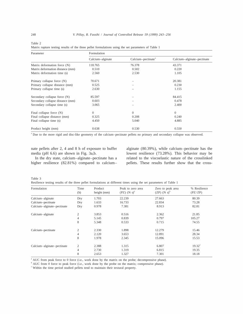
Table 2Matrix rupture testing results of the three pellet formulations using the set parameters of Table 1
Parameter FormulationaCalcium–alginate Calcium–pectinate Calcium–alginate–pectinate
Matrix deformation force (N) 118.765 76.378 43.371Matrix deformation distance (mm) 0.510 0.502 0.220Matrix deformation time (s) 2.560 2.530 1.105
Primary collapse force (N) 70.671 – 20.381Primary collapse distance (mm) 0.525 – 0.230Primary collapse time (s) 2.630 – 1.155
Secondary collapse force (N) 85.597 – 84.415Secondary collapse distance (mm) 0.603 – 0.478Secondary collapse time (s) 3.065 – 2.400
Final collapse force (N) 0 0 0Final collapse distance (mm) 0.325 0.208 0.240Final collapse time (s) 4.450 5.040 4.885
Product height (mm) 0.638 0.530 0.550a Due to the more rigid and disc-like geometry of the calcium–pectinate pellets no primary and secondary collapse was observed.
nate pellets after 2, 4 and 8 h of exposure to buffer alginate (80.39%), while calcium–pectinate has themedia (pH 6.6) are shown in Fig. 3a,b. lowest resilience (73.28%). This behavior may be
In the dry state, calcium–alginate–pectinate has a related to the viscoelastic nature of the crosslinkedhigher resilience (82.81%) compared to calcium– pellets. These results further show that the cross-
Table 3Resilience testing results of the three pellet formulations at different times using the set parameters of Table 1
Formulation Time Product Peak to zero area Zero to peak area % Resiliencea b(h) height (mm) (PZ) (N s) (ZP) (N s) (PZ/ZP)
Calcium–alginate Dry 1.703 22.239 27.663 80.39Calcium–pectinate Dry 1.633 16.733 22.834 73.28Calcium–alginate–pectinate Dry 0.978 7.381 8.913 82.81
Calcium–alginate 2 3.853 0.516 2.362 21.854 5.145 0.839 0.797 105.278 5.348 0.533 0.715 74.55
Calcium–pectinate 2 2.330 1.898 12.279 15.464 2.120 3.653 12.891 28.348 1.978 2.345 15.096 15.53
cCalcium–alginate–pectinate 2 2.388 1.315 6.807 19.324 2.730 1.319 6.815 19.358 2.653 1.327 7.301 18.18
a AUC from peak force to 0 force (i.e., work done by the matrix on the probe; decompressive phase).b AUC from 0 force to peak force (i.e., work done by the probe on the matrix; compressive phase).c Within the time period studied pellets tend to maintain their textural property.

V. Pillay, R. Fassihi / Journal of Controlled Release 59 (1999) 243 –256 249
during the earlier period, while around 8 h moreextensive degree of hydration and relaxation mayresult in the formation of a loose gel network.
3.4. MTDSC studies of the pellets
Initially, conventional DSC was performed, butthe thermograms did not show any significant ther-mal characteristics in order to establish differences inthe degrees of pellet crosslinking. The advantages ofMTDSC over conventional DSC, in terms of yield-ing information on the structure and processingeffects on various materials, are increasingly beingrecognized in pharmaceutical research [9–11]. Theheat flow signal of conventional DSC is basically thesummation of both the reversing heat flow [i.e.,changes in heat capacity such as molecular mobilityat glass transition (T )] and non-reversing heat flowg(i.e., kinetic components such as melting or crys-tallization) referred to as total heat. The MTDSCtechnique provides the capacity to deconvolute thesinusoidal (modulated) rate of temperature changeand underlying heat flow signals to reversing andnon-reversing components at any temperature. Thisis contrasted by the linear change employed inconventional DSC. Therefore, detection of changesin molecular mobility rather than a change of phasecan be easily characterized and this yields importantinformation on both processing effects and structuralchanges in the material over a range of temperatures.
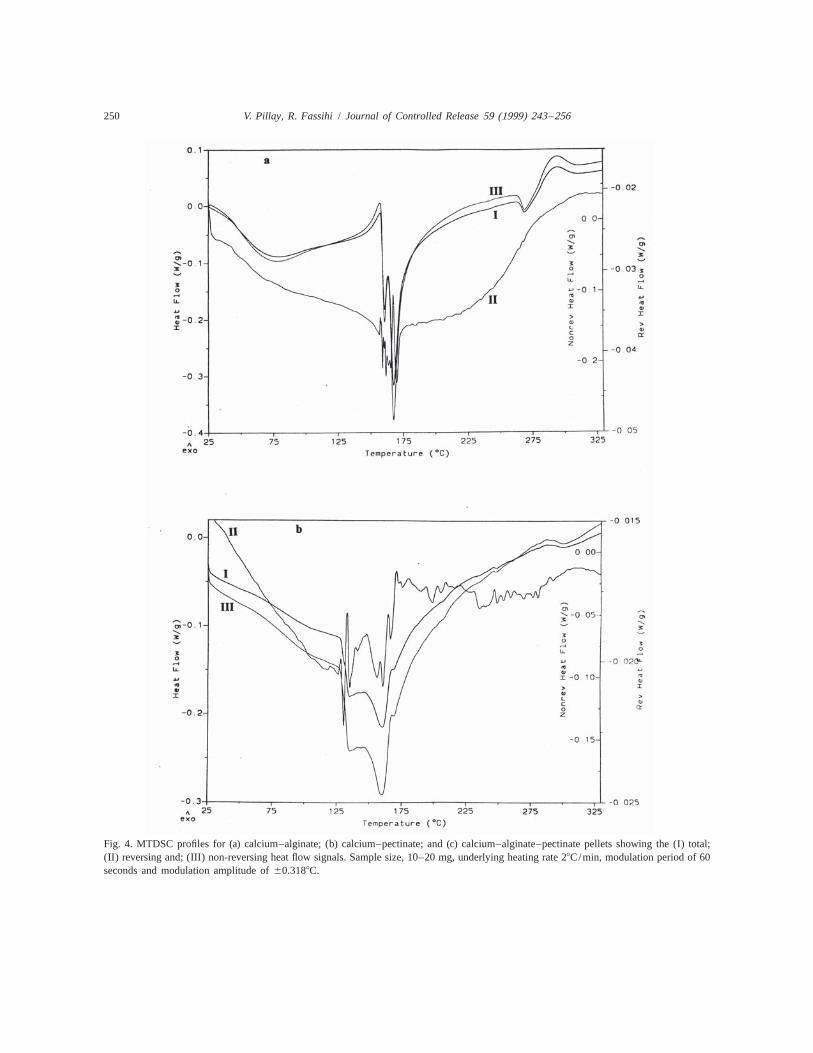
For crosslinked calcium–alginate pellets (Fig. 4a),the total heat flow signal shows a shallow transitiondisplayed between 50–1008C (peaks at 758C), fol-
Fig. 3. Typical force–time response obtained in matrix resilience lowed by the jagged endothermic region (150–analysis of: (a) dried pellets I, II and III corresponding to calcium– 1758C) and a relaxation endotherm at approximatelyalginate, calcium–pectinate and calcium–alginate–pectinate, re-
2608C. Examination of the reversing heat flow signalspectively; and (b) calcium–alginate–pectinate pellets after 2, 4clearly shows no glass transition while a superim-and 8 h of exposure to buffer medium at pH 6.6.posed endotherm in the non-reversing signal isapparent. This jagged endothermic region may be a
linked pectinate is less viscoelastic in nature com- result of the depolymerization process. Such tem-pared to crosslinked alginate and the binary mixture perature transition may be designated as T . Thedepol(Fig. 3a). smaller endotherm at ¯2608C is a result of the
With the exception of calcium–alginate–pectinate melting of diclofenac sodium, which was also ob-pellets, within each formulation it is observed that served for the calcium–pectinate and calcium–algi-there is an increase in the resilience during the first 4 nate–pectinate pellets (Fig. 4b,c). The initial shallowh of exposure to medium accompanied by a decrease transition seen in Fig. 4a may be attributed to thein resilience for the ensuing 4 h (see Table 3). This loss of adsorbed and entrapped moisture only, sincemay be attributed to the increased state of hydration the reversing heat flow did not show any transition
250 V. Pillay, R. Fassihi / Journal of Controlled Release 59 (1999) 243 –256
Fig. 4. MTDSC profiles for (a) calcium–alginate; (b) calcium–pectinate; and (c) calcium–alginate–pectinate pellets showing the (I) total;(II) reversing and; (III) non-reversing heat flow signals. Sample size, 10–20 mg, underlying heating rate 28C/min, modulation period of 60seconds and modulation amplitude of 60.3188C.

V. Pillay, R. Fassihi / Journal of Controlled Release 59 (1999) 243 –256 251
Fig. 4. (continued)
around 60–1008C. The concomitant rise in the 3.5. Evaluation of the thermal conductivity andcomplex heat capacity associated with the depoly- topographical images derived from micro-thermalmerization phase (not shown in Figure) may be analysisattributed to the increase in the free volume of thematerial as a result of crosslinkage disruption. The left panel of Fig. 5 (i.e., Fig. 5a,c,e) depicts
In the case of the calcium–pectinate matrices, it is the thermal conductivity images derived for cal-evident that the endothermic process of depolymeri- cium–alginate, calcium–pectinate and calcium–algi-zation is initiated much earlier (T 51258C; Fig. nate–pectinate pellets, respectively, while the rightdepol4b) compared to the calcium–alginate matrices panel images (Fig. 5b,d,f) show their corresponding(T 51508C; Fig. 4a). In addition, the relaxation topography for the same measurement area (i.e.,depolendotherm is manifested as a broad band rather than 20320 mm in each case). The color bars on the lefta clearly defined peak (125–1688C), indicating a panel for the thermal conductivity images (in mil-highly complex structure. In contrast, the depoly- liwatts, mW), range from dark to light intensity,merization endotherm for calcium–alginate–pecti- reflecting variations in thermal conductivity of mea-nate pellets (Fig. 4c) is typically closer to calcium– sured areas of each pellet; while the color bars on thealginate than calcium–pectinate. This may possibly right panel show variations for the topographicalpoint to an intermediate degree of crosslinking in the images (in nm) as a differential increase in samplecase of calcium–alginate–pectinate matrices (137– height (i.e., in z-axis motion). Based on a simulta-1708C). This classification for evaluating the degree neous comparison of the thermal conductivity andof crosslinking is comparable to the concept that the topographical images for each pellet formulation,T would increase with increasing polymeric cros- differences in contrast intensities show that theg
2slink density and vice versa [12,13]. Further exami- nature of the materials at 20 mm vary considerably.nation of the non-reversing heat flow signals in both In addition, such observation may also reflect theFig. 4b,c clearly show similar endothermic response. non-uniform crosslinking densities involved in the

252 V. Pillay, R. Fassihi / Journal of Controlled Release 59 (1999) 243 –256
Fig. 5. Micro-thermal analysis images: Left panel: Thermal conductivity images of calcium–alginate (a), calcium–pectinate (c) andcalcium–alginate–pectinate (e). Right panel: Topographical images of calcium–alginate (b), calcium–pectinate (d) and calcium–alginate–pectinate (f). All images rastered under isothermal conditions (608C) over 20320mm at a scan rate of 20 mm/s, 1 kHz frequency and200-line resolution.

V. Pillay, R. Fassihi / Journal of Controlled Release 59 (1999) 243 –256 253
pellet formation process. However, it must be noted Calcium–alginate pellets were essentially spheri-that this aspect of image analysis is new and requires cal in nature (Fig. 6a) while the calcium–pectinatefurther investigation. (Fig. 6b) and calcium–alginate–pectinate (Fig. 6c)
pellets were disc-like in geometry. This phenomenon3.6. Examination of surface morphology of pellets may be attributed to the different degrees of cross-by SEM linking occurring in each case. Based on MTDSC
study it is assumed that calcium–alginate pellets areFig. 6a–c depict the micrographs of individual more highly crosslinked than their pectinate and
pellets of calcium–alginate, calcium–pectinate and binary mixture counterparts. The possible explana-calcium–alginate–pectinate, respectively. Fig. 7a–c tion is that as soon as a droplet of sodium alginaterepresent their respective surface views at high makes contact with the calcium chloride solution,magnification. A minimum of three pellets randomly immediate peripheral crosslinking occurs. This as-sampled from each formulation batch were initially sists in the maintenance of the almost sphericalscanned to ensure batch homogeneity in both size shape. Upon this reaction, time-dependent crosslin-and geometry. kages are further formed to intercalate the outer
Fig. 6. Scanning electron micrographs of individual pellets: (a) calcium–alginate; (b) calcium–pectinate; and (c) calcium–alginate–pectinatepellets.

254 V. Pillay, R. Fassihi / Journal of Controlled Release 59 (1999) 243 –256
Fig. 7. Scanning electron micrographs of pellet surface at high magnification: (a) calcium–alginate; (b) calcium–pectinate; and (c)calcium–alginate–pectinate pellets.
matrix with the inwardly advancing gelled strikes) onto the calcium chloride solution, it trans-boundaries. Such a process is possible through the forms into a disc-like structure. This will result insequential diffusion of calcium ions throughout the inhibition of internal crosslinking reaction and en-internal matrix structure. This rapid ordered cross- hances water entrapment within the gelled matrix,linking process further allows matrix curing. Hence, with subsequent structural collapse upon drying. Itextensive molecular alignments during pellet forma- was visually observed that a similar phenomenontion plays a significant role in maintenance of the also occurred in the case of the calcium–alginate–calcium–alginate structure. Consequently, a surface pectinate pellets as well (Fig. 6c); however, to ascan of calcium–alginate reveals a more granular lower extent. Thus, collapse of pellets (Fig. 6b) may(Fig. 6a) and more uniformly aligned structure (Fig. in general be attributed to low degree of cross-7a). linking, as well as rapid and extensive dehydration
However, in the case of the calcium–pectinate upon drying. This latter effect is consistent with thematrices, in the initial phase of pellet formation, MTDSC profiles for calcium–alginate–pectinate pel-crosslinking caused some peripheral shrinkage (Fig. lets (Fig. 4c), showing no moisture loss in the6b). It was further noted that as the droplet fell (i.e., temperature range of 75–1008C as opposed to that

V. Pillay, R. Fassihi / Journal of Controlled Release 59 (1999) 243 –256 255
seen for calcium–alginate profiles (Fig. 4a). Moisture acting formulation components. This informationloss may be initiated as a result of the migration of may be of value to those scientists involved onwater to the peripheral surface and its attraction to controlled release dosage form design.calcium ions (calcium being highly hygroscopic).This might further point towards the lack of com-plete penetration /diffusion of calcium ions into the
Acknowledgementsinternal pectinate matrix. In addition, matrix rupturetesting revealed that the calcium–pectinate system is
We acknowledge the International Institute ofbrittle and consequently failed to display an inter–Education (IIE, USA) for award of the Fulbrightphasic rupture pattern as was demonstrated forScholarship to V.P. Both Dr. Gopi Venkatesh (seniorcalcium–alginate system (Fig. 1b). The inter-phasicinvestigator) and Mr. Charles Owusu–Fordjourrupture phenomenon may be related to the water-(technical support) (SmithKline Beecham Pharma-imparted plasticity of the matrix.ceuticals, Collegeville, USA) are acknowledged forAs a result of these disc-like conformations (Fig.their assistance in MTDSC and SEM studies. We6b,c), the structure appears to be fairly compressed,also thank Mr. Boine T. Johnson (Texture Tech-creating a diminished volume-area within each pelletnologies, New York) for providing us with thefor proper matrix cure and structural alignments.texture analyzer instrument, his technical expertiseConsequently, a more compact and non-uniformand support in making the texture analysis studysurface is observed for both calcium–pectinate (Fig.possible. Dr. Gray Slough from TA Instruments7b) and calcium–alginate–pectinate (Fig. 7c) pellets.(NewCastle, DE, USA) is acknowledged for assis-The greater alignment of the calcium–alginate struc-tance with the micro-thermal analysis experiments.ture (Fig. 7a) may be responsible for the higherAlso John Gibas (Fels Institute for Molecular Biolo-resilience (Table 3) than calcium–pectinate (Fig.gy and Cancer Research, Temple University) is7b). However, the similarities in surface morphologyacknowledged for help with developing scans of thebetween calcium–pectinate (Fig. 7b) and calcium–micro-thermal images.alginate–pectinate (Fig. 7c) is not reflected in resili-
ent behavior. Internal crosslinkages appear to play amajor role in supporting the polymer framework.
References
4. Conclusions [1] Pronova Biopolymer, Alginate as immobilization materialfor cells, Technical Sheets (1994) 1–4.
[2] A. Ravve, in: Principles of Polymer Chemistry, PlenumThis study has demonstrated that crosslinkedPress, New York, 1976, pp. 1–50.pellets of calcium–alginate, calcium–pectinate and
[3] A. Rubinstein, R. Radai, M. Ezra, S. Pathak, J.S. Rokem, Intheir binary mixture having different physical prop-vitro evaluation of calcium pectinate: a potential colon-erties, geometry, swelling and release behavior can specific drug delivery carrier, Pharm. Res. 10 (1993) 258–
be easily and reproducibly produced. Furthermore, 263.texture analysis of the pellet formulations illustrated [4] D.A. Adkin, C.J. Kenyon, E.I. Lerner, I. Landau, E. Strauss,
D. Caron, A. Penhasi, A. Rubinstein, I.R. Wilding, The usethat the incorporation of low methoxylated pectinof scintigraphy to provide ‘‘proof of concept’’ for noveltogether with a highly reactive alginate involved inpolysaccharide preparations designed for colonic drug deliv-the crosslinking reaction will determine the final ery, Pharm. Res. 14 (1997) 103–107.
degree of swelling, mechanical and resilience be- [5] H. Kim, R. Fassihi, A new ternary polymeric matrix systemhavior. Through an appreciation of the pellet matrix for controlled drug delivery of highly soluble drugs. I.
Diltiazem hydrochloride, Pharm. Res. 14 (1997) 1415–1421.structure via texture analysis, MTDSC and SEM, it[6] G.T. Grant, E.R. Moris, D.A. Rees, P.J.C. Smith, D. Thom,was possible to define the nature of crosslinking,
Biological interactions between polysaccharides and divalentdrug release kinetics and associated mechanisms. It cations: the Egg-box Model, FEBS Lett. 32 (1973) 195–198.is further apparent that different drug release profiles [7] Pronova Biopolymer, Technical information – alginates,can be easily achieved by proper selection of inter- Technical Sheets (1994) 3–14.

256 V. Pillay, R. Fassihi / Journal of Controlled Release 59 (1999) 243 –256
[8] M. Reiner, in: Deformation, Strain and Flow, H.K. Lewis with modulated temperature differential scanningand Co. Ltd., London, 3rd ed., 1969, pp. 98–100. calorimetry, J. Pharm. Sci. 87 (1998) 231–237.
[9] J.-M.E. Sarciaux, M.J. Hageman, Effects of bovine somatot- [12] S.S. Labana, Crosslinking, in: H.F. Mark, N.M. Bikales,ropin (rbSt) concentration at different moisture levels on the C.G. Overberger, G. Menges, J.I. Kroschwitz (Eds.), En-physical stability of sucrose in freeze–dried rbSt / sucrose cyclopedia of Polymer Science and Engineering, Vol. 4,mixtures, J. Pharm. Sci. 86 (1997) 365–371. Wiley, New York, 1986, pp. 350–395.
[10] E.C.A. Van Winden, W. Zhang, D.J.A. Crommelin, Effect of [13] R.-J. Roe, Glass transition, in: H.F. Mark, N.M. Bikales,freezing rate on the stability of liposomes during freeze– C.G. Overberger, G. Menges, J.I. Kroschwitz (Eds.), En-drying and rehydration, Pharm. Res. 14 (1997) 1151–1160. cyclopedia of Polymer Science and Engineering, Vol. 7,
[11] E.C.A. Van Winden, H. Talsma, D.J.A. Crommelin, Thermal Wiley, New York, 1987, pp. 531–544.analysis of freeze–dried liposome–carbohydrate mixtures