in-situ quasi-static and dynamic behavioural response · pdf file2 m. zeinoddini / in-situ...
TRANSCRIPT

1(2012) 1 – 19
In-Situ Quasi-Static and Dynamic Behavioural Response ofSteel Tubular Frames Subjected to Lateral Impact Loads
Abstract
Steel tubular members are widely used as primary and sec-
ondary structural framing members in offshore oil and gas
platforms. A platform is inherently liable to collisions from
ships which can create severe structural damages in the rig.
The effect of this damage has been studied by a number
of researchers through investigating the impact behaviour
isolated tubular members. This is while, the in-situ response
of a member located in a structural frame, to lateral im-
pact loads, is not necessarily the same as the response of an
individual isolated impacted member. In this paper the be-
haviour of a chord member forming part of a tubular frame,
subjected to impact loads, has been investigated. The tubu-
lar frame was tested experimentally by other researchers and
reported in the literature. The non-linear numerical models
of the frame presented by the authors have been validated
against the experimental results. These validated models
have been examined under both quasi-static and dynamic
impact loads with operational pre-loading applied. It has
been found that, in a pre-loaded frame, quasi-static impact
loading results in the failure of the impacted member. In-
terestingly, dynamic modelling of the impact results in the
dynamic instability of an adjacent bracing member. It has
been noticed that, under a dynamic impact, the impacted
in-situ member (located in the frame) behaves rather sim-
ilarly to a pin ended isolated member. With a quasi-static
impact, the impacted in-situ member follows fairly closely
the response obtained for a fixed ended isolated member.
Keywords
Impact, Frame, Tubular, Dynamic, Quasi-static and Failure
M. Zeinoddini
Department of Civil Engineering, K.N.Toosi
University of Technology, Tehran, Iran
Received 13 Apr 2012;In revised form 26 Apr 2012
∗ Author email: [email protected]
1
NOMENCLATURE2
Latin American Journal of Solids and Structures 1(2012) 1 – 19
2 M. Zeinoddini / In-Situ Quasi-Static and Dynamic Behavioural Response of Steel Tubular Frames Subjected to Lateral
Impact Loads
σy Material yield stress
D Tube diameter
E Material modulus of elasticity
F Concentrated lateral impact load
Fo Dynamic lateral step load
FP=8D2tσy/L Plastic collapse load of a tubular beam in pure bending
I Moment of inertia of the cross-section
L Tube length
m̄ m Mass per unit of length
P Push over load
Py=πDtσy Axial squash load of the tube
Pu Ultimate axial load of the tube
R Tube radius
t Tube wall thickness
T Natural period of vibration
3
1 INTRODUCTION4
Design of offshore structure components against a ship collision is generally based on available5
knowledge of the behaviour of damaged and impacted isolated tubular members. The majority6
of previous studies presented in the literature on ship-offshore collisions concentrate on the7
behaviour of isolated tubular members (Zeinoddini et al. [21, 22]). The behaviour of an8
impacted member when it is part of a structural frame is not necessarily the same as the9
behaviour of the corresponding isolated member, remote from the framework, subjected to a10
similar impact load.11
The differences between the response of a tubular member which is part of a structural12
frame (in-situ member) and an isolated member, when both are subjected to similar impact13
loads, are caused by several parameters. Interaction between the global modes of vibration in14
the frame and the member modes of deformation of the impacted member can create changes15
in the member response. In addition, the inertia forces and damping effects in the structural16
frame are different to those of an isolated member. The boundary conditions of an impacted17
in-situ member are a function of the connection properties and the stiffness of other members18
meeting at the connection. This type of semi-rigid boundary condition is different from the19
typical rigid or free end conditions considered in the literature for the study of isolated tubular20
members (Yao et al.[19]; Frieze and Cho[6]; Amdahl and Eberg[3]; Rambech and Dahl[12]; and21
Ricles and Bruin[13]). The boundary conditions of an in-situ impacted member are also likely22
to change during the impact. This occurs as a consequence of deformations in other members23
and in the connections.24
The main objective of the current study is to investigate the difference between the response25
of an impacted member which is part of a structural frame (an in-situ member) and the26
response of a similar isolated member. Such a study can link knowledge available in the27
Latin American Journal of Solids and Structures 1(2012) 1 – 19

M. Zeinoddini / In-Situ Quasi-Static and Dynamic Behavioural Response of Steel Tubular Frames Subjected to Lateral Impact
Loads 3
literature on the behaviour of impacted and damaged isolated tubular members to in-situ28
response which is closer to real behaviour.29
2 THE BENCH MARK TUBULAR FRAME30
2.1 Test Programme31
Structural frames have been tested experimentally by other researchers under vertical loads,32
lateral loads and base excitations (Martin and Villaverde[9]; and Mosalsm et al.,[10]). However,33
the authors of the current study are not aware of any relevant impact testing of tubular frames34
which can represent ship collisions with offshore structures. Large-scale tubular frames have35
also been tested under static push over loading by other researchers to study the failure of36
jacket frames (Grenda et al.[7]; Nichols et al.[11]; and Bolt[4]).37
The bench mark tubular frames mentioned above were found to be the most relevant38
available experimental work that could be used for validating the numerical impact model.39
The experimental results from these bench mark tubular frames have been used in this study40
for validating the non-linear numerical models of the frame with push over loading. If the41
non-linear numerical model can correlate with a push over collapse experiment, this provides42
some basis for using the model for the prediction of the dynamic behaviour, although it must43
be admitted that the accuracy of the some aspects of dynamic modelling remains uncertain.44
The experimental data, which were used for benchmarking the non-linear finite element45
models of tubular frames, emanate from the Phase I Frames Test Programme carried out in46
the placecountry-regionUK. This experimental push over test project was initiated in 1987.47
The programme was conducted by Billington Osborne-Moss Engineering Limited (BOMEL)48
as part of a joint industry programme with the object of providing test data on the collapse49
behaviour of jacket structures and in addition, to develop calibrated software for the non-linear50
push over analysis of framed structures (Bolt et al.[4]). The Phase I Frames Test Programme51
was completed in 1990 and provided the first large-scale test data on the collapse performance52
of frames representative of offshore structures. The results of this programme were released53
from confidentiality in 1993 (Lalani et al.[8]).54
The Phase I Frames Test Programme consisted of testing four, two bay, X-braced frames.55
These tubular frames (Figure 1 ) were the largest frameworks ever to be tested to collapse in56
a controlled manner, and provided a new and important insight into the role of redundancy57
and particularly tubular joint failures within a frame, neither of which have been investigated58
in earlier research programmes (Bolt et al.[25]).59
2.2 Numerical Models of the Bench Mark Frame60
The ABAQUS[1] non-linear finite element program has been used to produce two identical61
numerical models of the bench mark frame 1. In the first numerical model, each vertical,62
horizontal and diagonal member of the frame shown in Figure 1 has been modelled using63
up to 20 beam elements (type PIPE31 ). The connections are considered to be rigid and the64
frame supports are pinned. The second numerical model is the same as the first except that65
Latin American Journal of Solids and Structures 1(2012) 1 – 19
4 M. Zeinoddini / In-Situ Quasi-Static and Dynamic Behavioural Response of Steel Tubular Frames Subjected to Lateral
Impact Loads
one of the chord members in the upper bay has been modelled using shell elements. Twenty66
four shell elements (S4R) have been used in the circumference and fifty in the longitudinal67
direction of the chord member. The circumferential nodes at the two ends of this member have68
been linked to the end node of their adjacent beam element using the multi-point constraint69
option available in ABAQUS.70
The second model allows for local deformations in the chord member which is important71
in a ship impact study. The first numerical model excludes local deformation and denting.72
Comparing the results obtained from the first and the second models reveals the effect which73
local deformations have on the response of the frame.74
The first model, using only beam elements, is similar to models which have been used in75
the design against ship collision for the majority of existing offshore structures. The limited76
past capacity of computational facilities did not allow a time consuming analysis capable of77
including local effects in the appraisal (Sterndorff et al.[16]; and Waegter and Sterndorff[18]).78
It should be mentioned that no imperfection has been considered in the above mentioned79
numerical models.80
2.3 Validation of Numerical Models81
Figure 2 shows the horizontal load-displacement curves from the experimental results and in82
addition from the two numerical models when the frame is subjected to a push over horizontal83
load at its top. It can be seen that there is a good agreement between the test and the84
numerical results. Under push over loading no difference was found in the response of both85
of the numerical models. As a result, one curve in Figure 2 represents the response of both86
numerical models, with and without local deformations included.87
Buckling of the compression brace at the top half of the upper bay was reported to have88
caused failure in the test specimen. The same phenomenon was observed to have occurred89
in the numerical models. The ultimate lateral capacity of the frame tested was found to be90
920kN. The lateral capacity predicted by both the numerical models was found to be 932kN.91
3 RESPONSE TO QUASI-STATIC IMPACT LOADS92
3.1 Models of the Isolated Impacted Tubular Members93
The two numerical models of the test framework have been examined under lateral impact loads94
applied at mid length of a chord member in the frame upper bay. To be able to compare the95
results from the in-situ tubular members to the response of impacted isolated tubular members,96
two isolated chord members have also been modelled. Again in one model shell elements have97
been used which allow for the inclusion of local effects while in the other numerical model beam98
elements have been employed which model bowing but do not model local denting deformation99
behaviour.100
As a result, four numerical models have been considered; namely a frame with local effects;101
a frame without local effects; an isolated chord member with local effects and an isolated chord102
member without local effects. The geometry and other properties of the isolated chords are103
Latin American Journal of Solids and Structures 1(2012) 1 – 19

M. Zeinoddini / In-Situ Quasi-Static and Dynamic Behavioural Response of Steel Tubular Frames Subjected to Lateral Impact
Loads 5
1562
0mm
356
/ 12.
7 / 3
50
356
/ 19
.1 /
350
169 / 4.5 / 350
P
5944mm
356
/ 12.
7 / 3
50
169 / 4.5 / 290
169 / 4.5 / 290
169 / 4.5 / 290
169 / 9.5 / 390
Hinge Unit
169 / 7.65 / 3
20169 / 7.65 / 320
356
/ 19.
1 / 3
50
169
/ 6.3
/ 32
0169 / 6.3 / 320
169 / 4.5 / 290
169
/ 4.5
/ 29
0169 / 4.5 / 290
169
/ 4.45
/ 290
169
/ 4.6
/ 29
0
169 /
4.6 /
290
169 / 7.65 / 3
20169 / 7.65 / 320
∆
169 / 6.3 / 320
610x229x140kg UB GR 43B Yield = 320N/mm2
358x368x202kg UB GR 43B Yield = 320N/mm 2
Figure 1 Elevation and properties of the tubular frame (frame 1),used in the benchmarking exercise1 (Nicholset al., 1994)
the same as those of the impacted member in the frames.104
The boundary conditions at both ends of the isolated chord members allow for free axial105
sliding at each end of the member. However, ends are completely restrained against rota-106
tion. This boundary condition models, as closely as possible, the boundary conditions of the107
impacted member in the test frame although some axial restraints will be present.108
3.2 Pre-Loading109
A ship collision usually occurs when an offshore structure is carrying its operational load. The110
gravity and operational loads (called here pre-loading) can exacerbate the level of structural111
damage caused by a collision. With design safety factors, the operational pre-loading can be112
assumed to be, at maximum, between 50% and 70% of the ultimate axial load of the member113
(Pu). The former is the more likely load for a collision event and the latter is mostly associated114
with severe environmental load conditions. In this study only vertical pre-loading in the frame115
Latin American Journal of Solids and Structures 1(2012) 1 – 19

6 M. Zeinoddini / In-Situ Quasi-Static and Dynamic Behavioural Response of Steel Tubular Frames Subjected to Lateral
Impact Loads
Figure 2 Lateral push over load-displacement curves for test frame 1.
members (or axial compression in the isolated chord members) has been considered. The pre-116
loading in all models produces an axial compression in the chord member equal to 50% of the117
axial squash load of the member (Py).118
3.3 Response of Pre-Loaded Tubulars to Quasi-Static Impacts119
The four main numerical models have been studied under a quasi-static lateral impact load120
applied at the mid-span of the chord member. A Modified Riks method of analysis has been121
used because an impacted member experiences local and/or global instabilities in the tube122
wall or in overall. In non-linear finite element analysis, the Modified Riks Method is used for123
unstable static problems such as those found in post-collapse or post-buckling behaviour. The124
tangent stiffness matrix can be examined at any stage of the loading to determine the existence125
of negative eigenvalues. These can then be used to define the type of instability occurring in126
the structure. Figure 3 shows the response of the four main numerical models to a quasi-static127
impact load. The ordinate represents the dimensionless lateral load. The abscissa in Figure 3128
shows the dimensionless lateral deformation at the position of the impact load.129
When local effects are included in the numerical model, the maximum lateral load which130
can be resisted by the in-situ member is about 40% less than the maximum load carried when131
local effects are ignored. The ratio of corresponding values for the isolated chord member is132
about 33% with the model including local effects producing the lower value (Figure 3 ). The133
figure underlines the importance of including local effects in a collision study.134
Both isolated and in-situ chord members support similar maximum lateral loads when the135
local effects are excluded. The similar values for the maximum lateral loads obtained for136
the isolated and in-situ members indicate that with quasi-static impacts the rigid boundary137
conditions, considered for the isolated chord member, are fairly close to the real circumstances138
found in the structural frame.139
In the numerical models where local effects have been included, the peak load in the isolated140
member is slightly higher than the peak load obtained for the in-situ member. Reduction in141
Latin American Journal of Solids and Structures 1(2012) 1 – 19

M. Zeinoddini / In-Situ Quasi-Static and Dynamic Behavioural Response of Steel Tubular Frames Subjected to Lateral Impact
Loads 7
Figure 3 Lateral load-displacement behaviour of the isolated and in-situ tubular chord members subjected tolateral quasi-static impact.
the lateral load capacity indicates that the two ends of the damaged in-situ chord member142
exhibit a semi-rigid behaviour compared with the fully restrained condition for the isolated143
member. It will be seen later that with dynamic impact loads, considerably higher levels of144
semi-rigidity appear at the ends of the in-situ members.145
4 RESPONSE TO DYNAMIC IMPACT LOADS146
The four numerical models of frames and isolated members outlined in Section 3.1 have been,147
this time, examined under dynamic impact loads. As for previous models a pre-loading has148
been applied with all models and then lateral impact has been applied. An implicit incremental149
direct integration approach, based on the ‘Newmark method’, has been applied using the150
finite element program ABAQUS. In order to acquire a pure response which is not affected151
by modification of external loads and inertia forces during the impact, step lateral loads have152
been used initially hence providing a better understanding of the dynamic characteristics of153
the impact.154
In the current study no structural damping has been incorporated into the finite element155
models. The only existing damping in the analysis is the numerical Hilber-Huge damping156
incorporated in the finite element program. This damping is relatively small compared to157
structural damping. It should be mentioned that158
Obviously, some structural damping forces are involved in the response of the tubes to a159
dynamic load, but damping forces are generally believed not to impose a significant influence160
during the impact. This is because the duration of the impact is usually very short. In ordinary161
Latin American Journal of Solids and Structures 1(2012) 1 – 19
8 M. Zeinoddini / In-Situ Quasi-Static and Dynamic Behavioural Response of Steel Tubular Frames Subjected to Lateral
Impact Loads
structures, impact forces need a duration several times greater than the fundamental natural162
period of the system to have a remarkable effect on the response (Zeinoddini et al.[25]).163
4.1 Stable Responses164
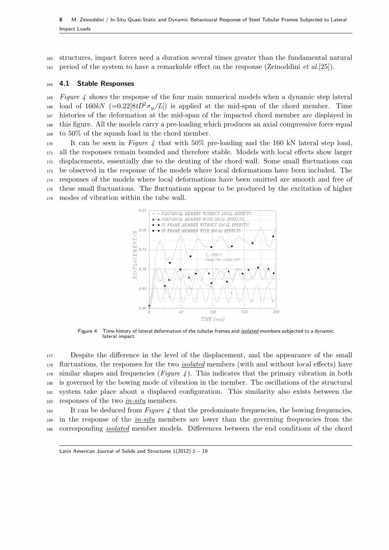
Figure 4 shows the response of the four main numerical models when a dynamic step lateral165
load of 160kN (=0.22[8tD2σy/L]) is applied at the mid-span of the chord member. Time166
histories of the deformation at the mid-span of the impacted chord member are displayed in167
this figure. All the models carry a pre-loading which produces an axial compressive force equal168
to 50% of the squash load in the chord member.169
It can be seen in Figure 4 that with 50% pre-loading and the 160 kN lateral step load,170
all the responses remain bounded and therefore stable. Models with local effects show larger171
displacements, essentially due to the denting of the chord wall. Some small fluctuations can172
be observed in the response of the models where local deformations have been included. The173
responses of the models where local deformations have been omitted are smooth and free of174
these small fluctuations. The fluctuations appear to be produced by the excitation of higher175
modes of vibration within the tube wall.176
Figure 4 Time history of lateral deformation of the tubular frames and isolatedmembers subjected to a dynamic
lateral impact.
Despite the difference in the level of the displacement, and the appearance of the small177
fluctuations, the responses for the two isolated members (with and without local effects) have178
similar shapes and frequencies (Figure 4 ). This indicates that the primary vibration in both179
is governed by the bowing mode of vibration in the member. The oscillations of the structural180
system take place about a displaced configuration. This similarity also exists between the181
responses of the two in-situ members.182
It can be deduced from Figure 4 that the predominate frequencies, the bowing frequencies,183
in the response of the in-situ members are lower than the governing frequencies from the184
corresponding isolated member models. Differences between the end conditions of the chord185
Latin American Journal of Solids and Structures 1(2012) 1 – 19
M. Zeinoddini / In-Situ Quasi-Static and Dynamic Behavioural Response of Steel Tubular Frames Subjected to Lateral Impact
Loads 9
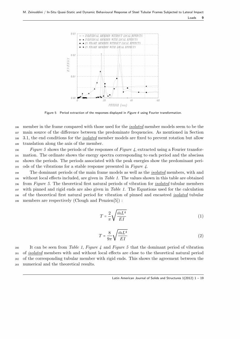
Figure 5 Period extraction of the responses displayed in Figure 4 using Fourier transformation.
member in the frame compared with those used for the isolated member models seem to be the186
main source of the difference between the predominate frequencies. As mentioned in Section187
3.1, the end conditions for the isolated member models are fixed to prevent rotation but allow188
translation along the axis of the member.189
Figure 5 shows the periods of the responses of Figure 4, extracted using a Fourier transfor-190
mation. The ordinate shows the energy spectra corresponding to each period and the abscissa191
shows the periods. The periods associated with the peak energies show the predominant peri-192
ods of the vibrations for a stable response presented in Figure 4.193
The dominant periods of the main frame models as well as the isolated members, with and194
without local effects included, are given in Table 1. The values shown in this table are obtained195
from Figure 5. The theoretical first natural periods of vibration for isolated tubular members196
with pinned and rigid ends are also given in Table 1. The Equations used for the calculation197
of the theoretical first natural period for vibration of pinned and encastred isolated tubular198
members are respectively (Clough and Penzien[5]) :199
T = 2
π
√m̄L4
EI(1)
T = 8
9π
√m̄L4
EI(2)
It can be seen from Table 1, Figure 4 and Figure 5 that the dominant period of vibration200
of isolated members with and without local effects are close to the theoretical natural period201
of the corresponding tubular member with rigid ends. This shows the agreement between the202
numerical and the theoretical results.203
Latin American Journal of Solids and Structures 1(2012) 1 – 19
10 M. Zeinoddini / In-Situ Quasi-Static and Dynamic Behavioural Response of Steel Tubular Frames Subjected to Lateral
Impact Loads
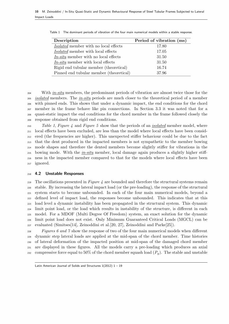
Table 1 The dominant periods of vibration of the four main numerical models within a stable response.
Description Period of vibration (ms)
Isolated member with no local effects 17.80
Isolated member with local effects 17.05
In-situ member with no local effects 31.50
In-situ member with local effects 31.50
Rigid end tubular member (theoretical) 16.74
Pinned end tubular member (theoretical) 37.96
With in-situ members, the predominant periods of vibration are almost twice those for the204
isolated members. The in-situ periods are much closer to the theoretical period of a member205
with pinned ends. This shows that under a dynamic impact, the end conditions for the chord206
member in the frame behave like pin connections. In Section 3.3 it was noted that for a207
quasi-static impact the end conditions for the chord member in the frame followed closely the208
response obtained from rigid end conditions.209
Table 1, Figure 4 and Figure 5 show that the periods of an isolated member model, where210
local effects have been excluded, are less than the model where local effects have been consid-211
ered (the frequencies are higher). This unexpected stiffer behaviour could be due to the fact212
that the dent produced in the impacted members is not sympathetic to the member bowing213
mode shapes and therefore the dented members become slightly stiffer for vibrations in the214
bowing mode. With the in-situ member, local damage again produces a slightly higher stiff-215
ness in the impacted member compared to that for the models where local effects have been216
ignored.217
4.2 Unstable Responses218
The oscillations presented in Figure 4 are bounded and therefore the structural systems remain219
stable. By increasing the lateral impact load (or the pre-loading), the response of the structural220
system starts to become unbounded. In each of the four main numerical models, beyond a221
defined level of impact load, the responses become unbounded. This indicates that at this222
load level a dynamic instability has been propagated in the structural system. This dynamic223
limit point load, or the load which results in instability of the structure, is different in each224
model. For a MDOF (Multi Degree Of Freedom) system, an exact solution for the dynamic225
limit point load does not exist. Only Minimum Guaranteed Critical Loads (MGCL) can be226
evaluated (Simitses[14], Zeinoddini et al.[20, 27], Zeinoddini and Parke[25]).227
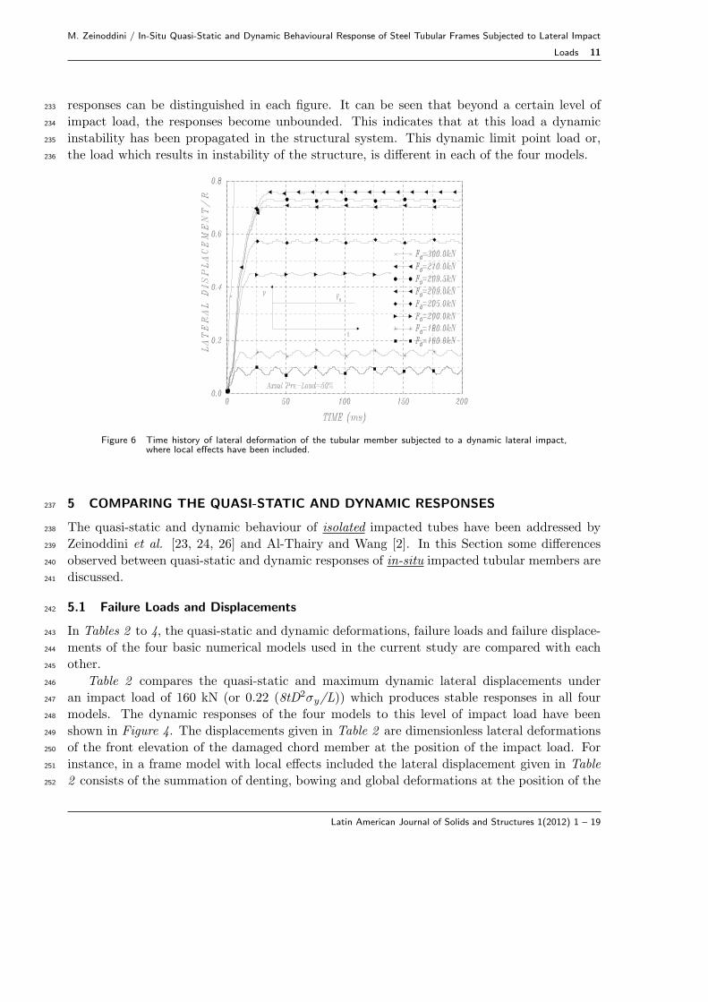
Figures 6 and 7 show the response of two of the four main numerical models when different228
dynamic step lateral loads are applied at the mid-span of the chord member. Time histories229
of lateral deformation of the impacted position at mid-span of the damaged chord member230
are displayed in these figures. All the models carry a pre-loading which produces an axial231
compressive force equal to 50% of the chord member squash load (Py). The stable and unstable232
Latin American Journal of Solids and Structures 1(2012) 1 – 19
M. Zeinoddini / In-Situ Quasi-Static and Dynamic Behavioural Response of Steel Tubular Frames Subjected to Lateral Impact
Loads 11
responses can be distinguished in each figure. It can be seen that beyond a certain level of233
impact load, the responses become unbounded. This indicates that at this load a dynamic234
instability has been propagated in the structural system. This dynamic limit point load or,235
the load which results in instability of the structure, is different in each of the four models.236
Figure 6 Time history of lateral deformation of the tubular member subjected to a dynamic lateral impact,where local effects have been included.
5 COMPARING THE QUASI-STATIC AND DYNAMIC RESPONSES237
The quasi-static and dynamic behaviour of isolated impacted tubes have been addressed by238
Zeinoddini et al. [23, 24, 26] and Al-Thairy and Wang [2]. In this Section some differences239
observed between quasi-static and dynamic responses of in-situ impacted tubular members are240
discussed.241
5.1 Failure Loads and Displacements242
In Tables 2 to 4, the quasi-static and dynamic deformations, failure loads and failure displace-243
ments of the four basic numerical models used in the current study are compared with each244
other.245
Table 2 compares the quasi-static and maximum dynamic lateral displacements under246
an impact load of 160 kN (or 0.22 (8tD2σy/L)) which produces stable responses in all four247
models. The dynamic responses of the four models to this level of impact load have been248
shown in Figure 4. The displacements given in Table 2 are dimensionless lateral deformations249
of the front elevation of the damaged chord member at the position of the impact load. For250
instance, in a frame model with local effects included the lateral displacement given in Table251
2 consists of the summation of denting, bowing and global deformations at the position of the252
Latin American Journal of Solids and Structures 1(2012) 1 – 19

12 M. Zeinoddini / In-Situ Quasi-Static and Dynamic Behavioural Response of Steel Tubular Frames Subjected to Lateral
Impact Loads
Figure 7 Time history of lateral deformation of the in-situ tubular member subjected to a dynamic lateralimpact, where local effects have not been included.
impact load.253
Table 2 Quasi-static and maximum dynamic lateral displacements of the four numerical models under stableimpact loading (F0=0.22 (8tD2σy/L) or 160kN).
Description Static Dynamic (Max) Dynamicdisplacement displacement Amplification FActor
/R /R (DAF)
Isolated member with 0.0229 0.0579 2.53local effects omitted (1.00) (2.73) (1.00)
Isolated member with 0.0298 0.1039 3.49local effects included (1.30) (4.54) (1.38)
In-situ member with 0.0590 0.1180 2.00local effects omitted (2.58) (5.15) (0.79)
In-situ member with 0.0705 0.2062 2.92local effects included (3.08) (9.00) (1.15)
To ease comparisons, the displacements have been normalised using the quasi-static re-254
sponse of the isolated member with local effects excluded, the normalised figures being given255
in brackets. It can be seen from Table 2 that the Dynamic Amplification Factor (the ratio256
between the maximum dynamic deformation and the corresponding static deformation) in257
the frame models is smaller than the similar values for the isolated member models. This is258
because the frame models have a relatively higher stiffness than the chord member. The Dy-259
namic Amplification Factor has an inverse relationship to the stiffness of the system. Dynamic260
Amplification Factors are higher when local effects are included. This difference is due to the261
Latin American Journal of Solids and Structures 1(2012) 1 – 19

M. Zeinoddini / In-Situ Quasi-Static and Dynamic Behavioural Response of Steel Tubular Frames Subjected to Lateral Impact
Loads 13
lower stiffness of the tube wall against lateral loading compared to the bowing stiffness of the262
member.263
Tables 3 and 4 give the quasi-static and dynamic failure loads and failure displacements of264
the four main numerical models, respectively. The failure loads are the maximum lateral loads265
that can be resisted by the models. The failure displacements are the corresponding lateral266
displacements at the mid-span of the impacted member.267
Table 3 Quasi-static and maximum dynamic lateral failure displacements of the four numerical models underextreme impact loading.
Description Quasi-static Dynamic Dynamic failurefailure failure displacement/quasi-
displacement/R displacement/R static displacement
Isolated member with 0.112 0.344 3.07local effects omitted (1.00) (3.07) (1.00)
Isolated member with 0.618 0.758 1.23local effects included (5.52) (6.77) (0.40)
In-situ member with 0.316 0.443 1.40local effects omitted (2.82) (3.96) (0.46)
In-situ member with 0.725 0.871 1.20local effects included (6.47) (7.78) (0.39)
Table 4 Quasi-static and maximum dynamic lateral failure loads of the four numerical models under extremeimpact loading.
Description Static failure Dynamic failure Dynamic failure load/load(8tD2σy/L) load(8tD2σy/L) quasi-static failure load
Isolated member with 0.619 0.393 0.63local effects omitted (1.00) (0.63) (1.00)
Isolated member with 0.415 0.284 0.68local effects included (0.67) (0.46) (1.08)
In-situ member with 0.617 0.385 0.62local effects omitted (1.00) (0.62) (0.98)
In-situ member with 0.373 0.259 0.69local effects included (0.60) (0.42) (1.09)
With a quasi-static impact, a maximum load value can be obtained and the corresponding268
displacement can be calculated (see Figure 3 ). With a dynamic impact load, no exact failure269
load can be defined. The dynamic failure loads given in Table 4 correspond to the oscillation270
immediately below the Minimum Guaranteed Critical Loads. These load values appear to be271
close to the exact dynamic failure load. The dynamic failure displacements presented in Table272
3 correspond to the load values mentioned above. These may not be close to collapse values273
because of the potential rapid change in this critical region.274
Latin American Journal of Solids and Structures 1(2012) 1 – 19
14 M. Zeinoddini / In-Situ Quasi-Static and Dynamic Behavioural Response of Steel Tubular Frames Subjected to Lateral
Impact Loads
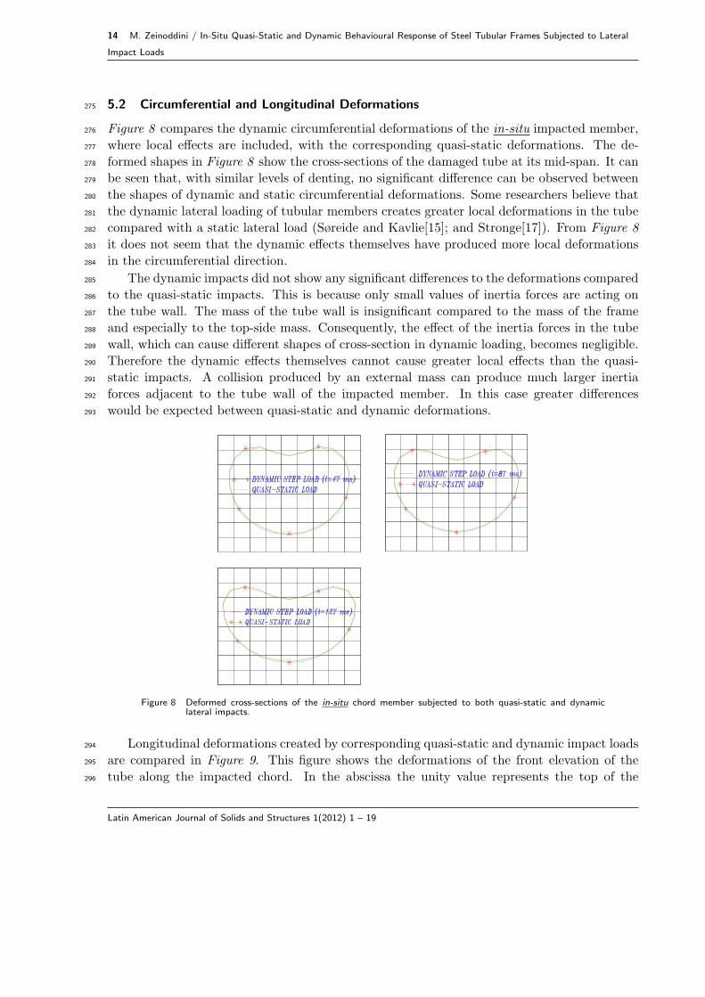
5.2 Circumferential and Longitudinal Deformations275
Figure 8 compares the dynamic circumferential deformations of the in-situ impacted member,276
where local effects are included, with the corresponding quasi-static deformations. The de-277
formed shapes in Figure 8 show the cross-sections of the damaged tube at its mid-span. It can278
be seen that, with similar levels of denting, no significant difference can be observed between279
the shapes of dynamic and static circumferential deformations. Some researchers believe that280
the dynamic lateral loading of tubular members creates greater local deformations in the tube281
compared with a static lateral load (Søreide and Kavlie[15]; and Stronge[17]). From Figure 8282
it does not seem that the dynamic effects themselves have produced more local deformations283
in the circumferential direction.284
The dynamic impacts did not show any significant differences to the deformations compared285
to the quasi-static impacts. This is because only small values of inertia forces are acting on286
the tube wall. The mass of the tube wall is insignificant compared to the mass of the frame287
and especially to the top-side mass. Consequently, the effect of the inertia forces in the tube288
wall, which can cause different shapes of cross-section in dynamic loading, becomes negligible.289
Therefore the dynamic effects themselves cannot cause greater local effects than the quasi-290
static impacts. A collision produced by an external mass can produce much larger inertia291
forces adjacent to the tube wall of the impacted member. In this case greater differences292
would be expected between quasi-static and dynamic deformations.293
Figure 8 Deformed cross-sections of the in-situ chord member subjected to both quasi-static and dynamic
lateral impacts.
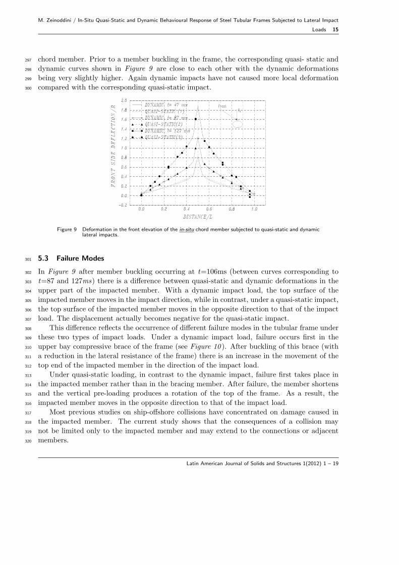
Longitudinal deformations created by corresponding quasi-static and dynamic impact loads294
are compared in Figure 9. This figure shows the deformations of the front elevation of the295
tube along the impacted chord. In the abscissa the unity value represents the top of the296
Latin American Journal of Solids and Structures 1(2012) 1 – 19
M. Zeinoddini / In-Situ Quasi-Static and Dynamic Behavioural Response of Steel Tubular Frames Subjected to Lateral Impact
Loads 15
chord member. Prior to a member buckling in the frame, the corresponding quasi- static and297
dynamic curves shown in Figure 9 are close to each other with the dynamic deformations298
being very slightly higher. Again dynamic impacts have not caused more local deformation299
compared with the corresponding quasi-static impact.300
Figure 9 Deformation in the front elevation of the in-situ chord member subjected to quasi-static and dynamiclateral impacts.
5.3 Failure Modes301
In Figure 9 after member buckling occurring at t=106ms (between curves corresponding to302
t=87 and 127ms) there is a difference between quasi-static and dynamic deformations in the303
upper part of the impacted member. With a dynamic impact load, the top surface of the304
impacted member moves in the impact direction, while in contrast, under a quasi-static impact,305
the top surface of the impacted member moves in the opposite direction to that of the impact306
load. The displacement actually becomes negative for the quasi-static impact.307
This difference reflects the occurrence of different failure modes in the tubular frame under308
these two types of impact loads. Under a dynamic impact load, failure occurs first in the309
upper bay compressive brace of the frame (see Figure 10 ). After buckling of this brace (with310
a reduction in the lateral resistance of the frame) there is an increase in the movement of the311
top end of the impacted member in the direction of the impact load.312
Under quasi-static loading, in contrast to the dynamic impact, failure first takes place in313
the impacted member rather than in the bracing member. After failure, the member shortens314
and the vertical pre-loading produces a rotation of the top of the frame. As a result, the315
impacted member moves in the opposite direction to that of the impact load.316
Most previous studies on ship-offshore collisions have concentrated on damage caused in317
the impacted member. The current study shows that the consequences of a collision may318
not be limited only to the impacted member and may extend to the connections or adjacent319
members.320
Latin American Journal of Solids and Structures 1(2012) 1 – 19
16 M. Zeinoddini / In-Situ Quasi-Static and Dynamic Behavioural Response of Steel Tubular Frames Subjected to Lateral
Impact Loads
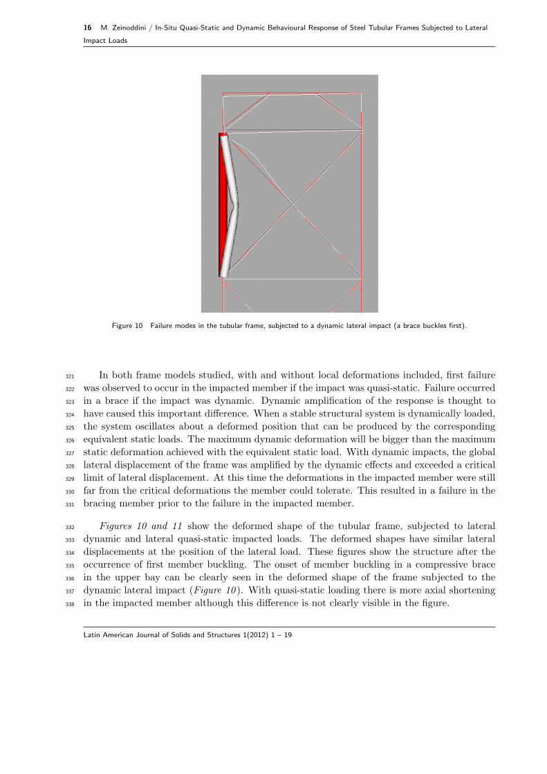
Figure 10 Failure modes in the tubular frame, subjected to a dynamic lateral impact (a brace buckles first).
In both frame models studied, with and without local deformations included, first failure321
was observed to occur in the impacted member if the impact was quasi-static. Failure occurred322
in a brace if the impact was dynamic. Dynamic amplification of the response is thought to323
have caused this important difference. When a stable structural system is dynamically loaded,324
the system oscillates about a deformed position that can be produced by the corresponding325
equivalent static loads. The maximum dynamic deformation will be bigger than the maximum326
static deformation achieved with the equivalent static load. With dynamic impacts, the global327
lateral displacement of the frame was amplified by the dynamic effects and exceeded a critical328
limit of lateral displacement. At this time the deformations in the impacted member were still329
far from the critical deformations the member could tolerate. This resulted in a failure in the330
bracing member prior to the failure in the impacted member.331
Figures 10 and 11 show the deformed shape of the tubular frame, subjected to lateral332
dynamic and lateral quasi-static impacted loads. The deformed shapes have similar lateral333
displacements at the position of the lateral load. These figures show the structure after the334
occurrence of first member buckling. The onset of member buckling in a compressive brace335
in the upper bay can be clearly seen in the deformed shape of the frame subjected to the336
dynamic lateral impact (Figure 10 ). With quasi-static loading there is more axial shortening337
in the impacted member although this difference is not clearly visible in the figure.338
Latin American Journal of Solids and Structures 1(2012) 1 – 19

M. Zeinoddini / In-Situ Quasi-Static and Dynamic Behavioural Response of Steel Tubular Frames Subjected to Lateral Impact
Loads 17
Figure 11 Failure modes in the tubular frame, subjected to a quasi-static lateral impact (the chord memberbuckles first).
6 CONCLUDING REMARKS339
The response of an in-situ member in a structural frame subject to a lateral impact load340
is not necessarily the same as the response of an isolated impacted member. In this paper341
the behaviour of a chord member forming part of a tubular frame subjected to impact loads342
has been investigated. The tubular frame was tested experimentally by other researchers and343
reported in the literature. Non-linear numerical models of the frame have been validated344
using the experimental test results. These validated models have been examined under both345
quasi-static and dynamic impact loads with operational pre-loading applied. Some of the main346
differences between the response of a laterally impacted in-situ member and a corresponding347
isolated member have been reported in this paper.348
With dynamic loading the impacted in-situ member has been found to behave rather349
similarly to that expected from an isolated member with pinned end conditions. With a quasi-350
static impact, the impacted in-situ member follows fairly closely the response obtained for a351
fixed ended isolated member. The end rigidity of the tubular member has a direct influence352
on the effective length of the member, which can subsequently affect the axial design load353
carrying capacity.354
In the current study no significant difference has been found between the dynamic and355
quasi-static circumferential and longitudinal deformations, although some researchers believe356
that dynamic impact loads produce more local deformations in tubular members compared357
Latin American Journal of Solids and Structures 1(2012) 1 – 19

18 M. Zeinoddini / In-Situ Quasi-Static and Dynamic Behavioural Response of Steel Tubular Frames Subjected to Lateral
Impact Loads
with a quasi-static load.358
Whether or not local deformations have been included, first failure in the frame was ob-359
served to occur in the impacted member, if the impact was quasi-static. Failure occurred360
in a brace when the impact was dynamic. Most previous studies of ship-offshore collisions361
have concentrated on damage caused to the impacted member. The current study shows that362
the consequences of a collision may not be limited only to the impacted member but can ex-363
tend to the connections and/or adjacent members. Some potential modes of failure might be364
overlooked if a quasi-static method of analysis is selected.365
It should be emphasised that the results presented in this paper do not give a complete366
picture of the in-situ behaviour of laterally impacted steel tubular members. They are, however,367
able to illustrate some of the key factors involved. The tubular frame used in this study was a368
two bay, two dimensional frame. Real structures are more complex than this two dimensional369
benchmark frame. However, a number of important phenomena have been identified which370
will assist in future collapse analyses of complex offshore structures using non-linear software371
to determine the ultimate, and residual strengths of platforms.372
References373
[1] SIMULIA, ’ABAQUS analysis and theory manuals’, SIMULIA, the Dassault Systmes, Realistic Simulation, Provi-374
dence, 2009.375
[2] H. Al-Thairy and Y.C. Wang. A numerical study of the behaviour and failure modes of axially compressed steel376
columns subjected to transverse impact. International Journal of Impact Engineering, 38(8-9):732–744, 2011.377
[3] J. Amdahl and E. Eberg. ship collision with offshore structures, in structural dynamics eurodyn93. pages 495–504,378
1993.379
[4] H.M. Bolt, K. Billington, and K. Ward. Results from large scale ultimate load tests of k-braced jacket frame structures.380
1995.381
[5] R.W. Clough and J. Penzien. Dynamics of Structures. McGraw-Hill Inc., 1993.382
[6] P.A. Frieze and S.R. Cho. Impact damage and assessment of offshore tubulars. In 25th Offshore Technology Confer-383
ence,, pages 193–200, 1993.384
[7] K.G. Grenda, W.C. Glawson, and Shinners C.D. Large-scale ultimate strength testing of tubular k-braced frames.385
pages 16–18, 1988.386
[8] M. Lalani. New large scale frame data on the reserve and residual strength of frames. 1993.387
[9] S.C. Martin and R. Villaverde. Collapse analysis of steel frame structures under earthquake. volume 1, pages 370–373,388
1996.389
[10] K.M. Mosalam, R.N. White, and G. Ayala. Response of infilled frames using pseudo-dynamic experimentation.390
Journal of Earthquake Engineering and Structural Dynamic, 27:6, 1998.391
[11] N.W Nichols, J.C.P. Kam, and J.V. Sharp. Benchmarking of collapse analysis of large scale ultimate load tests on392
tubular jacket frame structure. pages 2.2.1–2.2.29, 1994.393
[12] J.F. Rambech and T. Dahl. Capacity of stiffened tubular cross section subjected to concentrated load impact from394
ship collision. volume 1, pages 449–461, 1994.395
[13] J.M. Ricles and M.W. Bruin. Evaluation of analysis methods for response prediction of dent-damaged tubular steel396
bracing members. pages 215–228, 1998.397
[14] G.J. Simitses. Dynamic Stability of Suddenly Loaded Structures. Springer-Verlag, 1990.398
[15] T.H. Sreide and D. Kavile. collision damages and residual strength of tubular members in steel offshore structure, in399
shell structures stability and strength. pages 185–220, 1985.400
Latin American Journal of Solids and Structures 1(2012) 1 – 19

M. Zeinoddini / In-Situ Quasi-Static and Dynamic Behavioural Response of Steel Tubular Frames Subjected to Lateral Impact
Loads 19
[16] M.J. Sterndorff, J. Waegter, and C. Eilersen. Design of fixed offshore platforms to dynamic ship impact loads.401
Engineering Fracture Mechanics, 114:146–153, 1992.402
[17] W.J. Stronge. impact on metal tubes: Indentation and perforation, in structural crashworthiness and failure. Inter-403
national Journal of Solids and Structures, pages 165–188, 1993.404
[18] J. Waegter and M.J. Sterndorff. Energy absorption in monotower platforms during ship collision. pages 235–243.405
Technical report, FIB Bulletin 14, 1995.406
[19] T. Yao, J. Taby, and T. Moan. Ultimate strength and post-ultimate strength behaviour of damaged tubular members407
in offshore structures. Journal of Offshore Mechanics and Arctic Engineering, Transaction of the ASME, 110(3):254–408
62, 1988.409
[20] M. Zeinoddini, M. Abdolvahab, and J. Keyvani. Preloading effects on the behaviour of cylindrical members of jacket410
platforms subjected to ship impact. pages 10–15, 2007.411
[21] M. Zeinoddini, J.E. Harding, and G.A.R. Parke. Effect of impact damage on the capacity of tubular steel members412
of offshore structures. Journal of Marine Structures, 11(4-5):141–158, 1998.413
[22] M. Zeinoddini, J.E. Harding, and G.A.R. Parke. Dynamic behaviour of axially pre-loaded tubular steel members of414
offshore structures subjected to impact damage. Journal of Ocean Engineering, 26:963–978, 1999.415
[23] M. Zeinoddini, J.E. Harding, and G.A.R. Parke. Contribution of ring resistance in the behaviour of steel tubes416
subjected to a lateral impact. International Journal of Mechanical Sciences, 42(12):2303–2320, 2000.417
[24] M. Zeinoddini, J.E. Harding, and G.A.R. Parke. Axially pre-loaded steel tubes subjected to lateral impacts - a418
numerical simulation. International Journal of Impact Engineering, 35(11):1267–1279–328, 2002.419
[25] M. Zeinoddini and G.A.R. Parke. Dynamic shakedown and degradation of elastic reactions in laterally impacted steel420
tubes. International Journal of Damage Mechanics, 20(3):400–422, 2011.421
[26] M. Zeinoddini, G.A.R. Parke, and J.E. Harding. Axially pre-loaded steel tubes subjected to lateral impacts an422
experimental study. International Journal of Impact Engineering, 27(6):669–690, 2002.423
[27] M. Zeinoddini, G.A.R. Parke, and J.E. Harding. Interface forces in laterally impacted steel tubes. International424
Journal of Experimental Mechanics, 48(5):265 280, 2008.425
Latin American Journal of Solids and Structures 1(2012) 1 – 19
