in power transformers 1 · 2010-05-09 · modeling and calculating the in-rush currents in power...
TRANSCRIPT
Damascus Univ. Journal Vol. (21)-No. (1)2005 Abou-Safe - Kettleborough
75
Modeling and Calculating the In-Rush Currents in Power Transformers 1
Abdolmutaleb Abou-Safe2 Gordon Kettleborough3
Abstract This paper presents a mathematical model for an unloaded saturated transformer and predicts the in-rush current when the transformer is connected to the power supply. The model uses non-linear core parameters (R0 and L0 ), which vary according to the magnetic state and properties of the non-linear core. The results of this research show the risks of connecting an unloaded power transformer to the power system. It is recommended that this phenomenon is taken into account when protection devices on the transformer are adjusted, to avoid mal-operations and consequent tripping of the transformer circuit breaker. A comparison between experimental and simulated results, shows a good agreement and prove the validity of the model for detailed study of in-rush current phenomenon.
1 For the paper in Arabic see pages (207 -208). 2 Power Engineering Department, FMEE , Damascus University. 3 Electronic and Electrical Engineering Department, Loughborough University,U.K.
Modeling and calculating the In-rush Currents in Power Transformers
76
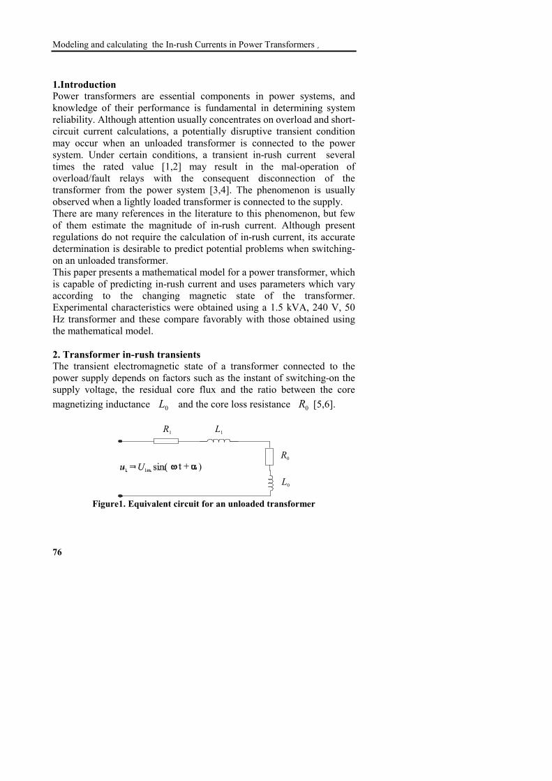
1.Introduction Power transformers are essential components in power systems, and knowledge of their performance is fundamental in determining system reliability. Although attention usually concentrates on overload and short- circuit current calculations, a potentially disruptive transient condition may occur when an unloaded transformer is connected to the power system. Under certain conditions, a transient in-rush current several times the rated value [1,2] may result in the mal-operation of overload/fault relays with the consequent disconnection of the transformer from the power system [3,4]. The phenomenon is usually observed when a lightly loaded transformer is connected to the supply. There are many references in the literature to this phenomenon, but few of them estimate the magnitude of in-rush current. Although present regulations do not require the calculation of in-rush current, its accurate determination is desirable to predict potential problems when switching-on an unloaded transformer. This paper presents a mathematical model for a power transformer, which is capable of predicting in-rush current and uses parameters which vary according to the changing magnetic state of the transformer. Experimental characteristics were obtained using a 1.5 kVA, 240 V, 50 Hz transformer and these compare favorably with those obtained using the mathematical model. 2. Transformer in-rush transients The transient electromagnetic state of a transformer connected to the power supply depends on factors such as the instant of switching-on the supply voltage, the residual core flux and the ratio between the core magnetizing inductance 0L and the core loss resistance 0R [5,6].
)
R1 L1
R0
L0
Figure1. Equivalent circuit for an unloaded transformer

Damascus Univ. Journal Vol. (21)-No. (1)2005 Abou-Safe - Kettleborough
77
The magnetizing inductance 0L and core loss resistance 0R may be represented as series impedances as shown in figure 1 , with 1R and
1L representing respectively the primary winding resistance and leakage inductance. Assuming the transformer supply voltage has a sinusoidal waveform
)sin(11 αω += tUu m , the no-load in-rush current is defined by the first order differential equation
)1()(sin/ 100 αω +=+ tUiRdtidL
where 0i is the instantaneous no-load current, 01 LLL += and 01 RRR += .
Equation (1) cannot be determined analytically due to the nonlinearity of the magnetizing inductance 0L . Thus the equation should be re-written as a function of the magnetic core flux Φ . The relationship between the no- load current 0i , the magnetizing inductance 0L and the flux is:
where 1N is the number of primary turns. Substituting equation (2) in equation (1) gives
)3()(sin)/(/ 111 αω +=Φ+Φ tULRNdtdN m
Assuming L is constant, equation (3) is a linear differential equation with constant parameters. The solution may be written as a function of the flux in the form
)4(ap Φ+Φ=Φwhere: )sin( ϕαω −+Φ=Φ tmp is the periodic component of flux.
)2(100 Φ= NiL

Modeling and calculating the In-rush Currents in Power Transformers
78
The maximum amplitude mΦ may be calculated from:
)5(/ 11 NU mm ω=Φ
In general LR ω⟨⟨ and it may be assumed that °− ≈= 90/tan 1 RLωϕ .Thus
)6()cos( αω +Φ−=Φ tmp
The transient component of the flux aΦ is an exponentially decaying function:
tLRa Ce )/(−=Φ
The constant C comprises two components; the residual core flux rΦ± , which in some cases may approach 50% of component mΦ [5],
and a component which negates the periodic component at the instant t = 0. Thus rmC Φ±Φ= αcos and
)7()cos( )/( tLRrma e−Φ±Φ=Φ α
The final form of the resultant transient is
)8()cos( )/( tLRrm e−Φ±Φ α++Φ−=Φ )cos( αω tm
Equation (8) shows that the transient value of the magnetic flux depends on the supply voltage phase angle α at the instance of switching, and on the residual flux value rΦ . If α = 2/π at the instance of connection and
rΦ is 0, the resultant flux will settled instantly at its steady- state periodic value )sin( tm ωΦ=Φ and the current in the transformer takes
Damascus Univ. Journal Vol. (21)-No. (1)2005 Abou-Safe - Kettleborough
79
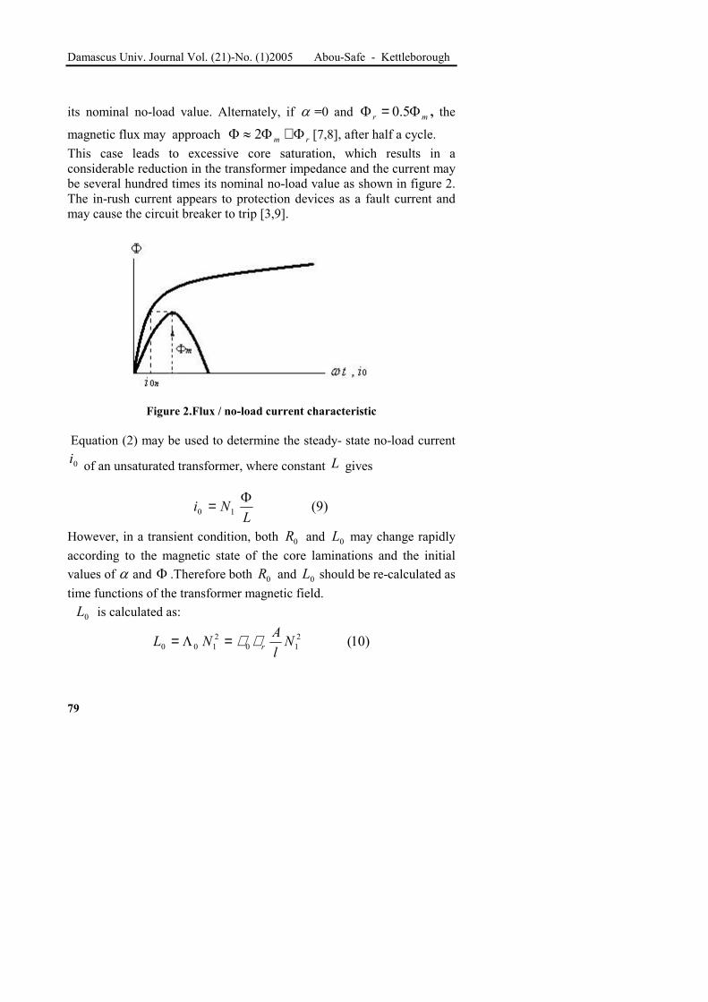
its nominal no-load value. Alternately, if α =0 and mr Φ=Φ 5.0 , the magnetic flux may approach rm Φ+Φ≈Φ 2 [7,8], after half a cycle. This case leads to excessive core saturation, which results in a considerable reduction in the transformer impedance and the current may be several hundred times its nominal no-load value as shown in figure 2. The in-rush current appears to protection devices as a fault current and may cause the circuit breaker to trip [3,9].
Figure 2.Flux / no-load current characteristic Equation (2) may be used to determine the steady- state no-load current 0i of an unsaturated transformer, where constant L gives
)9(10 LNi Φ=
However, in a transient condition, both 0R and 0L may change rapidly according to the magnetic state of the core laminations and the initial values of α and Φ .Therefore both 0R and 0L should be re-calculated as time functions of the transformer magnetic field. 0L is calculated as:
)10(210
2100 Nl
ANL rµµ=Λ=

Modeling and calculating the In-rush Currents in Power Transformers
80
where- 0Λ is the core magnetic permeance [Wb/A]; rµµ ,0 respectively the permeability of free space [Wb/Am] and the relative permeability; A is the cross sectional area of the magnetic core [m2] and l is the equivalent length of the magnetic circuit [m]. The relative permeability is determined using the magnetization curve
)(HfB = :)11(
0 HB
r µµ =
The magnetic flux density is
)12(AB Φ=
0L changes from its steady-state ( maximum ) value to some transient value '
0L in accordance with the ratio
)13(''' 210
210
0
0
r
r
r
r
NlA
NlA
LL
µ
µ
µµ
µµ==
Thus the transient value of the inductance is
)14(''
00r
rLLµ
µ=
The core- loss resistance 0R varies with saturation and its transient value '
0R may be determined from

Damascus Univ. Journal Vol. (21)-No. (1)2005 Abou-Safe - Kettleborough
81
)15('
''
2'00
200
20
0
2'0
0
0
0iPiP
iPiP
RR ==
where 0P is the steady-state core loss. Assuming this value is proportional to flux density squared, the core loss change from 0P to '
0Pwhen the flux density changes from 0B to 'B is
2
20
0
0'' B
BPP =
Thus the transient core loss is
)16('
'20
2
00 BB
PP =
Assuming 0LL ≈ the current change may be determined from the ratio
r
r
BB
LBLB
LL
LN
LN
ii
µµ
''
''
''
'''
0
0
00
00
00
0
01
0
01
0
0 ==ΦΦ=
Φ
Φ=
giving
Substituting equations (1-16) and (1-17) in equation (1-15) gives
)18(24'
2'40
0'0
r
rBBRR
µµ=
)17('''0
00r
r
BBii
µ
µ=
Modeling and calculating the In-rush Currents in Power Transformers
82
Since 0R and 0L reduce considerably in the transient condition, the primary winding resistance 1R and leakage inductance 1L must be taken into account. Thus the equivalent transient resistance and inductance of the transformer are respectively
1'0 RRR += and 1'
0 LLL += (19) and the transient flux is
)20()cos( )/( tLRrm e−Φ±Φ α++Φ−=Φ )cos( αω tm
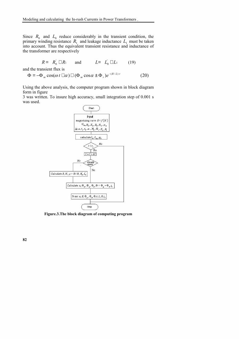
Using the above analysis, the computer program shown in block diagram form in figure 3 was written. To insure high accuracy, small integration step of 0.001 s was used.
Figure.3.The block diagram of computing program
Damascus Univ. Journal Vol. (21)-No. (1)2005 Abou-Safe - Kettleborough
83
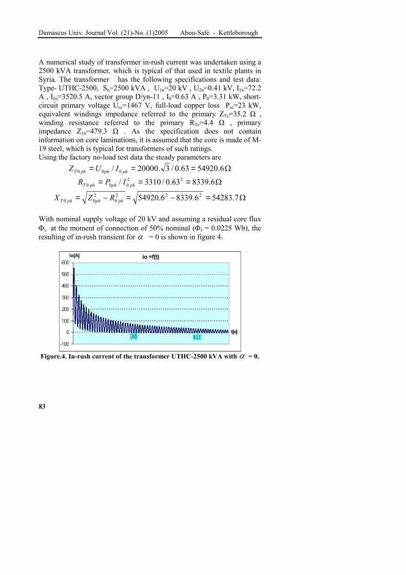
A numerical study of transformer in-rush current was undertaken using a 2500 kVA transformer, which is typical of that used in textile plants in Syria. The transformer has the following specifications and test data: Type- UTHC-2500, Sn=2500 kVA , U1n=20 kV , U2n=0.41 kV, I1n=72.2 A , I2n=3520.5 A, vector group D/yn-11 , I0=0.63 A , P0=3.31 kW, short-circuit primary voltage Usc=1467 V, full-load copper loss Psc=23 kW, equivalent windings impedance referred to the primary ZTe=35.2 Ω ,winding resistance referred to the primary RTe=4.4 Ω , primary impedance Z1n=479.3 Ω . As the specification does not contain information on core laminations, it is assumed that the core is made of M-19 steel, which is typical for transformers of such ratings. Using the factory no-load test data the steady parameters are
Ω=== 6.5492063.0/3.20000/ 000 phphphT IUZΩ=== 6.833963.0/3310/ 22
000 phphphT IPRΩ=−=−= 7.542836.83396.54920 222
0200 phphphT RZX
With nominal supply voltage of 20 kV and assuming a residual core flux Φr at the moment of connection of 50% nominal (Φr = 0.0225 Wb), the resulting of in-rush transient for α = 0 is shown in figure 4.
Figure.4. In-rush current of the transformer UTHC-2500 kVA with α = 0.
Modeling and calculating the In-rush Currents in Power Transformers
84
The peak in-rush current of 554 A is about seven and half times the rated load current, which decays to its no-load value in 1.5 s. Comparing these results with similar experimental results [2,3,4] shows that the peak in-rush current varies between four and ten times the rated load current, depending on the transformer ratings and its magnetic core specifications. The transient decay is typically 1.2-1.5 s.

Damascus Univ. Journal Vol. (21)-No. (1)2005 Abou-Safe - Kettleborough
85
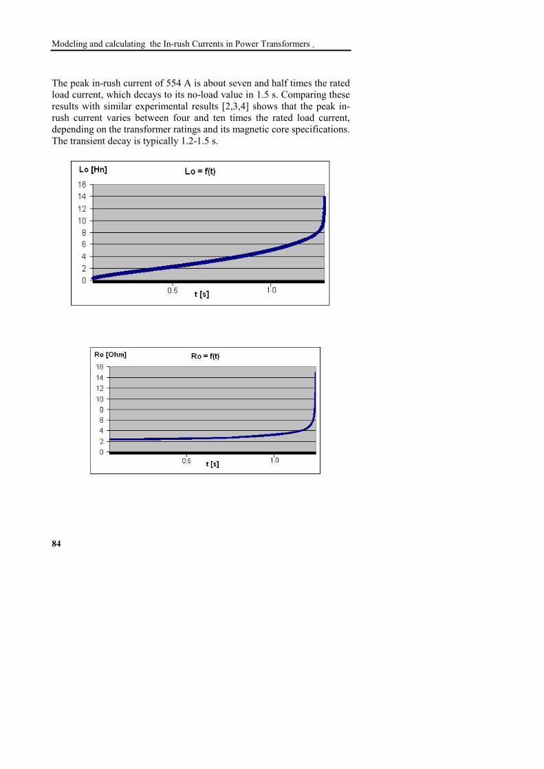
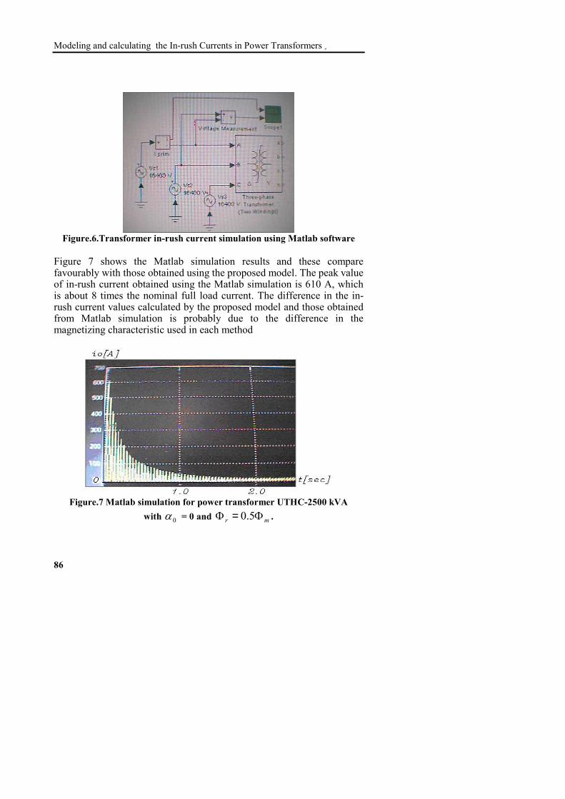
Figure.5.Theoretical variation of L0 , R0 and core flux for α = 0. Figure.5 shows the appreciable effect of saturation on L0 and R0 . Initially they are small and the resulting transformer impedance consists mainly of the primary winding impedance R1+jX1. As the transient progresses, L0and R0 increase until they eventually assume their normal values. Initially they increase slowly then more rapidly as they approach their steady state unsaturated values. The non-linear properties of the core also appear in the magnetic flux, where it is observed that it decays slowly during heavy saturation, then rapidly during the last stage of the transient as it approaches its nominal value. The peak flux in this case is about 2.5 its nominal value, which confirms the theoretical concepts of this phenomenon. The accuracy of prediction of the proposed model was compared with that obtained using Matlab software package 6.5. The transient was simulated using a set of elements from the Matlab library including a three-phase two-winding saturable transformer of the same specifications, three single-phase sinusoidal voltage sources each of 16400 V , measuring and displaying devices to monitor the in-rush current and voltage waveforms as shown in figure 6.
Modeling and calculating the In-rush Currents in Power Transformers
86
Figure.6.Transformer in-rush current simulation using Matlab software Figure 7 shows the Matlab simulation results and these compare favourably with those obtained using the proposed model. The peak value of in-rush current obtained using the Matlab simulation is 610 A, which is about 8 times the nominal full load current. The difference in the in-rush current values calculated by the proposed model and those obtained from Matlab simulation is probably due to the difference in the magnetizing characteristic used in each method
Figure.7 Matlab simulation for power transformer UTHC-2500 kVA with 0α = 0 and mr Φ=Φ 5.0 .

Damascus Univ. Journal Vol. (21)-No. (1)2005 Abou-Safe - Kettleborough
87
As further verification for the proposed model , an experimental study was undertaken on a single-phase laboratory transformer type EMTU-TTO1, having the following specifications: Sn=1500 VA , U1n=240 V , U2n=240 V, I1n=6.25 A , I2n=6.25 A. The following results were obtained from no-load and short-circuit tests: U0=U1n=240 V ، I0=0.123 A , P0=15 W, short-circuit primary voltage Usc=48 V, Psc =97.5 W, Isc = I1n =6.25 A. These results gave the following equivalent circuit parameters:
Ω=== 2.1951123.0/240/ 000 IUZ,Ω=== 5.991123.0/15/ 22
000 IPRΩ=−=−= 6.168047.99122.1951 222
0200 RZX ,
Ω=== 7.725.6/48/ ... cscscs IUZ,Ω=== 5.225.6/5.97/ 22
... cscscs IPRΩ=−=−= 3.75.268.7 222
.2.. cscscs RZX .
The B/H magnetizing characteristic for the transformer was obtained from the no-load test for various values of no-load current and corresponding no-load voltage. The equations used for determining values of B and H are :
)21(44.40 wf KTABfU = ,)22(0 lHTi f =
where the power supply frequency f = 50 Hz; the cross sectional area of the core 24105.12 mA −×= ; 95.0=wK ; the average core length
ml 45.0= .From equation (21) ,
wf KTAfUB 44.4
0=

Modeling and calculating the In-rush Currents in Power Transformers
88
and from equation (22)
lTiH f0=
The resulting B/H characteristic is shown in figure 8.
Figure8.Experimental magnetizing characteristic for laboratory transformer EMTU- TTO1
Using the magnetizing characteristic of figure 8, the in-rush current for the test transformer was determined using the new model, when the supply voltage phase angle α = 0 . The resulting transient is shown in figure 9. The peak in-rush current is 35.3 A, which is about 6 times the nominal load current. The transient decays during the relatively short time of about 0.25 sec, which may be explained by the high ratio of R0 to X0 in a small transformer. On the other hand, the peak magnetic flux is 0.0054 Wb, which is about 2.5 its nominal value. Its aperiodic component decays within the same decaying time as the in-rush current.

Damascus Univ. Journal Vol. (21)-No. (1)2005 Abou-Safe - Kettleborough
89
Figure.9.Simulated in-rush current and magnetic core flux for the laboratory transformer ( o0=α ).
The experimental in-rush current for the laboratory transformer, with
o0=α is shown in figure10. The peak value of the inrush current is about 36 A, and the transient decays in about 0.25 sec.

Modeling and calculating the In-rush Currents in Power Transformers
90
Figure.10.Experemental in-rush current for the laboratory transformer ( α = 0).
A simulation of the laboratory transformer connected to the power supply at o90=α is shown in figure11. As expected, the current in this case settles immediately to its steady state value.
Figure.11.simulated in-rush current for the laboratory transformer ( o90=α ).

Damascus Univ. Journal Vol. (21)-No. (1)2005 Abou-Safe - Kettleborough
91
The experimental result for this condition is shown in figure12 and again, it is observed that the transient is negligible and the current instantaneously assumes its steady-state value of 0.13 A.
Figure.12.Experemental in-rush current for the laboratory transformer ( o90≈α ).
Conclusions: This paper presents a mathematical model for an unloaded saturated transformer and predicts the in-rush current when the transformer is connected to the power supply. The model uses non-linear core parameters (R0 and L0 ), which vary according to the magnetic state of the non-linear core. A comparison between experimental and simulated results, shows a good agreement and proves the validity of this model for studying in-rush current. The results of this research show the risks of connecting an unloaded power transformer to the power system. It is recommended that this phenomenon is taken into account when protection devices on the transformer are adjusted, to avoid mal-operations and consequent tripping of the transformer circuit breaker.
Modeling and calculating the In-rush Currents in Power Transformers
92
References
[1] D.A. Koppikar, and others. A modified approach to overfluxing analysis of transformers. Electrical Power &Energy Systems, Vol. 20, No.4, pp. 235-239, Elsevier Science Ltd.1998. [2] Michael Steurer and Klaus Fröhlich, “The Impact of Inrush Currents on the Mechanical Stress of High Voltage Power Transformer Coils,” IEEE Trans. On Power Delivery, vol. 17, no. 1, pp. 155–160, January 2002. [3] Moises Gomes-Morante and Denise W. Nicoletti. , “A Wavelet based Differential Transformer Protection,” IEEE Trans. On Power Delivery, vol. 14, no. 4, pp. 1351–1358, October 1999. [4] Smith, K.S. Ran and L. Leyman, B. , “Analysis of transformer inrush transients in offshore electrical systems,” IEEE Proceedings on Generation, Transmission and Distribution, vol. 146, no. 1, pp. 89–95, January 1999. [5] Brusekin A. and others. Electrical machines and micro machines." High school" publications, Moscow, 1990. [6] J. Jesus Rico, Enrique Acha, and Manuel Madrigal, “The Study of Inrush Current Phenomenon Using Operational Matrices,” IEEE Trans. On Power Delivery, vol. 16, no. 2, pp. 231–237, April 2001. [7] Karen L. Butler-Purry, and Mustafa Bagriyanik, “Characterization of Transients in Transformers Using Discrete Wavelet Transforms,” IEEE Trans. On Power Systems, vol. 18, no. 2, pp. 648–656, May 2003. [8] Philip Kiameh. Electrical equipment handbook . McGraw-Hill Book Co., New York,2003. [9] H. Zang, J.F. Wen and others. Discrimination between fault and magnetizing inrush current in transformers using short-time correlation transform. Electrical Power &Energy Systems, Vol. 24, pp. 557-562, Elsevier Science Ltd.2002.
Received, 3 June, 2004.