imrt planning basics - ssu.ac.irssu.ac.ir/.../parto_darmani/matlab_amoozeshi/slide/imrt.pdf · imrt...
TRANSCRIPT

IMRT Planning BasicsAAMD Student Webinar
March 12, 2014Karen Chin Snyder, MS
Senior Associate Physicist
Department of Radiation Oncology

Disclosures
The presenter has received speaker honoraria from Varian Medical Systems.
Presentation Sponsored by Varian Medical System
Medical Advice DisclaimerVarian as a medical device manufacturer cannot and does not recommend
specific treatment approaches. Individual treatment results may vary.

Varian Medical SystemsFair Balance Safety Statement
Intended Use SummaryVarian Medical Systems’ linear accelerators are intended to provide stereotactic radiosurgery and precision radiotherapy for lesions, tumors, and conditions anywhere in the body where radiation treatment is indicated.
SafetyRadiation treatments may cause side effects that can vary depending on the part of the body being treated. The most frequent ones are typically temporary and may include, but are not limited to, irritation to the respiratory, digestive, urinary or reproductive systems, fatigue, nausea, skin irritation, and hair loss. In some patients, they can be severe. Treatment sessions may vary in complexity and time. Radiation treatment is not appropriate for all cancers.

IMRT Planning Concepts Definition of IMRT Beam setup Objectives and NTO Optimization Fluence smoothing Leaf Motion Calculator Advanced techniques: base plans, SIB

What is IMRT?Intensity Modulated Radiotherapy
Can include:SBRT: Stereotactic Body Radiotherapy
- Higher dose per fraction, extra-cranial, less fractions
SRS: Stereotactic Radiosurgery
- Higher dose per fraction, one fraction, inter-cranial
VMAT: Volumetric Modulated Arc Radiotherapy aka RapidArc
- Conventional fractionation schemes, gantry, dose rate can vary
SRT: Stereotactic Radiotherapy
- Higher dose per fraction, multiple fxs, inter-cranial
http://aapp.org/blog/health-care-acronyms-wtheck/

Fixed-Gantry IMRTUse MLCs to create non-uniform fluences for many fields to create uniform dose distribution within the target that spares critical structures simultaneously
Cheung. Intensity modulated radiotherapy: advantages, limitations and future developments. Biomed Imaging Iterv J 2006; 2(1): e19
Yokoyama et al. Surface buildup dose dependence on photon field delivery technique for IMRT Department of Radiation Oncology, JACMP Vol5 No2, 2004
Non uniform fluence
BEV of fluence
Beamlet
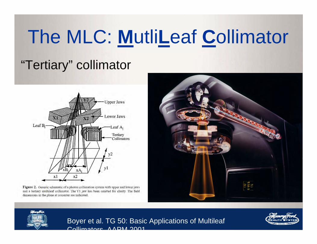
The MLC: MutliLeaf Collimator“Tertiary” collimator
Boyer et al. TG 50: Basic Applications of MultileafCollimators AAPM 2001

Common Types of Varian MLC
Millennium 120 MLC- 0.5 cm inner- 1cm outer
HD-MLC- 0.25 cm inner- 0.5 cm outer

Leaf SequencingMLC leaf sequencing – tells the MLCs how to move in order to deliver given fluenceMSS
– Multiple static segment– “Step-and-shoot”– Segmental MLC
Sliding Window– Sweeping gap– Moving window
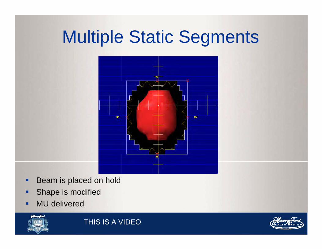
Multiple Static Segments
Beam is placed on hold Shape is modified MU delivered
THIS IS A VIDEO

Sliding Window
Leaves are continuously moving in one direction while beam is on Amount of radiation is controlled by the speed of the leaves and the
gap between the leaves
THIS IS A VIDEO

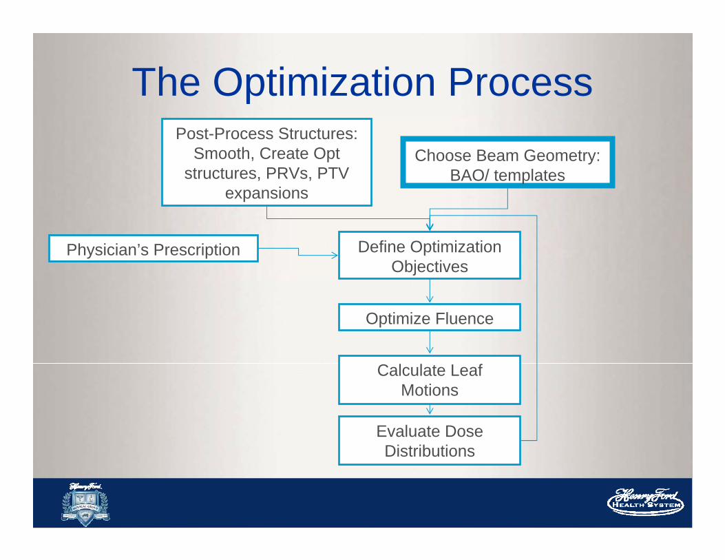
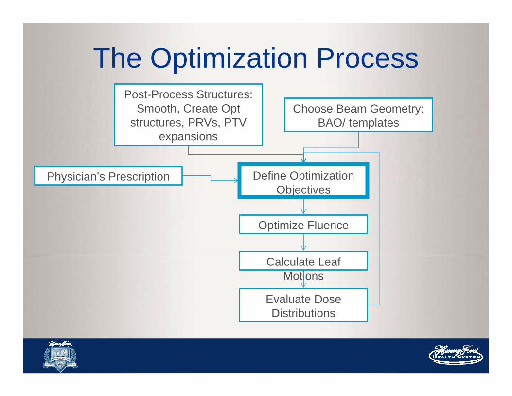
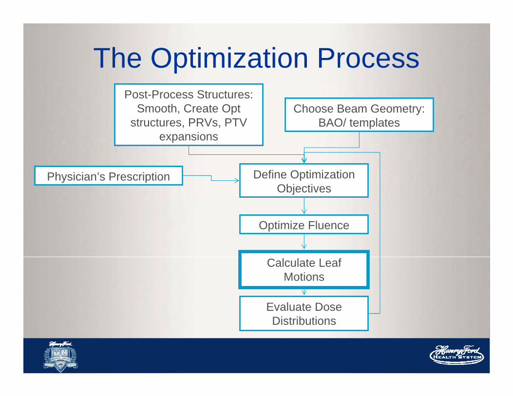
The Optimization ProcessPost-Process Structures:
Smooth, Create Opt structures, PRVs, PTV
expansions
Choose Beam Geometry: BAO/ templates
Physician’s Prescription Define Optimization Objectives
Optimize Fluence
Calculate Leaf Motions
Evaluate Dose Distributions

The Optimization ProcessPost-Process Structures:
Smooth, Create Opt structures, PRVs, PTV
expansions
Choose Beam Geometry: BAO/ templates
Physician’s Prescription Define Optimization Objectives
Optimize Fluence
Calculate Leaf Motions
Evaluate Dose Distributions
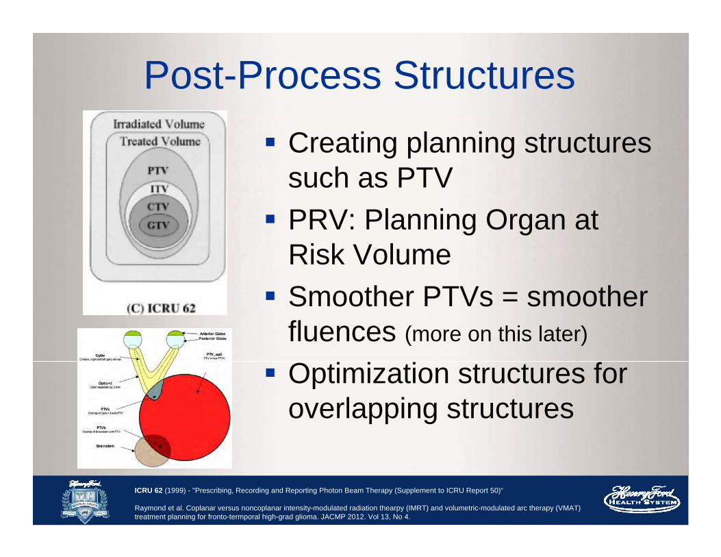
Post-Process Structures Creating planning structures
such as PTV PRV: Planning Organ at
Risk Volume Smoother PTVs = smoother
fluences (more on this later)
Optimization structures for overlapping structures
ICRU 62 (1999) - "Prescribing, Recording and Reporting Photon Beam Therapy (Supplement to ICRU Report 50)“
Raymond et al. Coplanar versus noncoplanar intensity-modulated radiation thearpy (IMRT) and volumetric-modulated arc therapy (VMAT) treatment planning for fronto-termporal high-grad glioma. JACMP 2012. Vol 13, No 4.
The Optimization ProcessPost-Process Structures:
Smooth, Create Opt structures, PRVs, PTV
expansions
Choose Beam Geometry: BAO/ templates
Physician’s Prescription Define Optimization Objectives
Optimize Fluence
Calculate Leaf Motions
Evaluate Dose Distributions
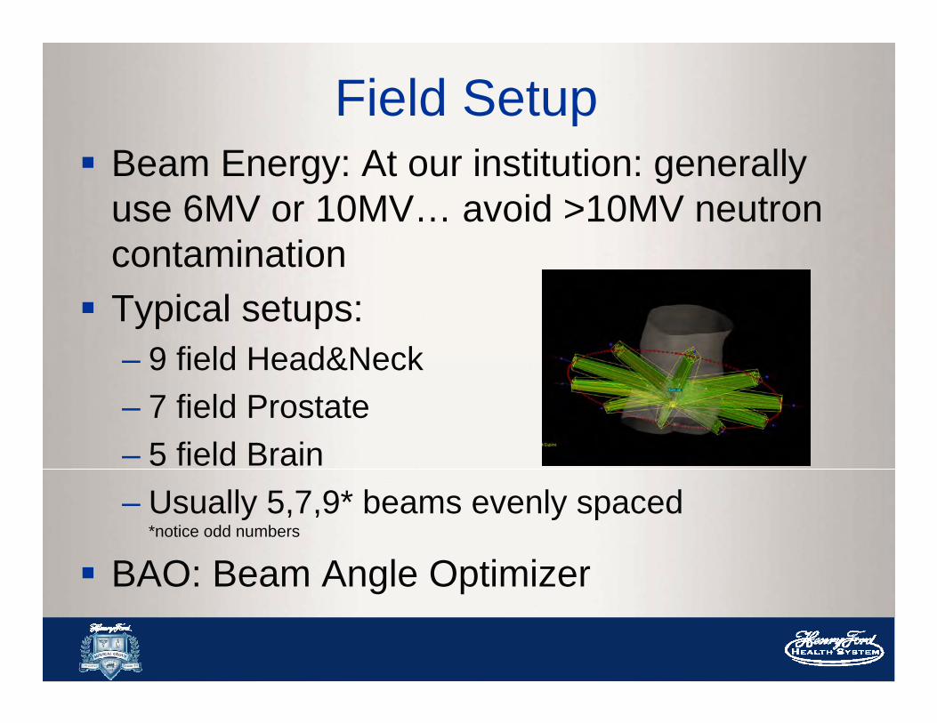
Field Setup Beam Energy: At our institution: generally
use 6MV or 10MV… avoid >10MV neutron contamination Typical setups:
– 9 field Head&Neck– 7 field Prostate– 5 field Brain– Usually 5,7,9* beams evenly spaced
*notice odd numbers
BAO: Beam Angle Optimizer

Avoid Parallel Opposed BeamsAllow the system better achieve a solutionThe parallel opposed fields share the same
beamlets/fluence map
5 degrees or more apart are recommended

Field GeometryAvoid Beams Directed Through Radiosensitive OARs
Non co-planar beams.
Example: Avoid Eyes/Lens in Brain Cases -Vertex Beam (non coplanar)

Optimized Collimator Rotation
Chapek et al. Optimization of Collimator Parameters to Reduce Rectal Dose in Intensity-Modulated Prostate Treatment Planning. Medical Dosimetry 2005 Vol. 30, No 4, p 205-212

Fixed/Locked Jaws
Pacemaker = 2Gy
Fixed Field
Tumor Dose = 48Gy
Jaw Transmission ~ 0.1% compared to MLC ~ 1.5%

But Remember! Be practical
– Time to treat at machine: couch kicks are time consuming
– Patients can move Weigh the benefit of a more complicated
plan And, be nice to your therapists
The Optimization ProcessPost-Process Structures:
Smooth, Create Opt structures, PRVs, PTV
expansions
Choose Beam Geometry: BAO/ templates
Physician’s Prescription Define Optimization Objectives
Optimize Fluence
Calculate Leaf Motions
Evaluate Dose Distributions

Physician’s Prescription
OARs
PTV and Rx
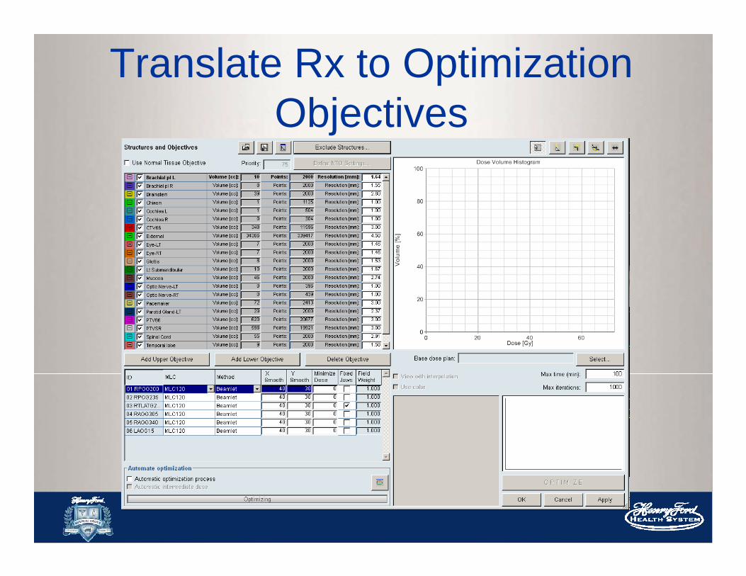
Translate Rx to Optimization Objectives

What the optimizer needs to know…
Type of objective: upper vs lower Normal tissue objective Clinical goal dose Priority
Note: These are just starting points…optimization is interactive and changes can be made during optimization

3 Types of Objectives
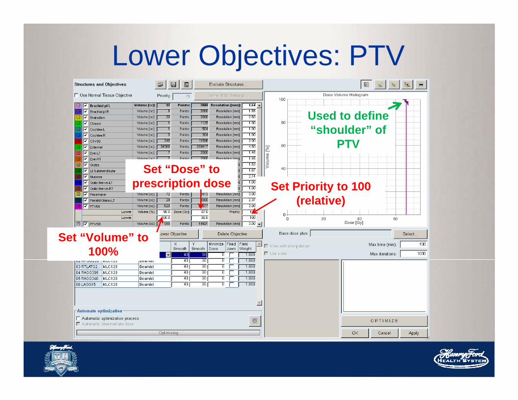
Lower Objectives: PTV
Used to define “shoulder” of
PTV
Set “Dose” to prescription dose Set Priority to 100
(relative)
Set “Volume” to 100%

Upper Objectives: PTV
Used to define “tail”
of PTV
Set “Dose” to 105 -108% of prescription
dose
Set “Volume” to 0%
Set Priority to 100(relative)

Upper Objectives: OARs
Set “Dose” to Goal
Set “Volume” to 0% for MAX
Set Priority (relative)
Recall:
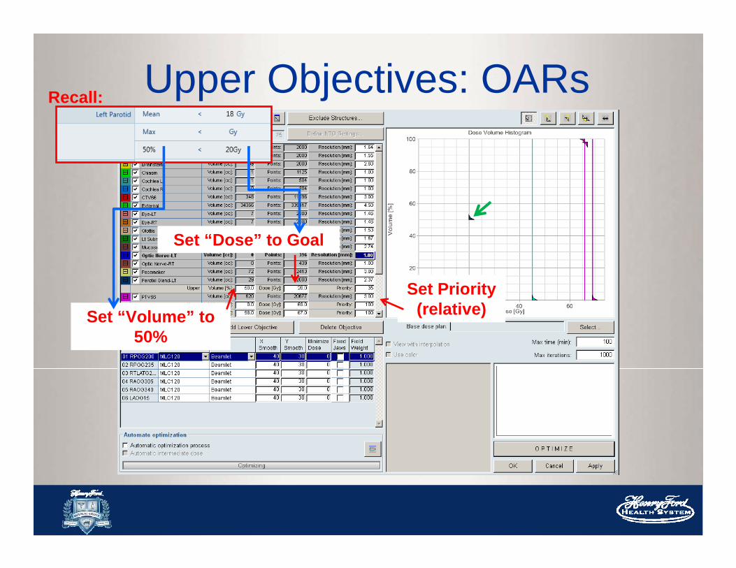
Upper Objectives: OARs
Set “Dose” to Goal
Set “Volume” to 50%
Set Priority (relative)
Recall:
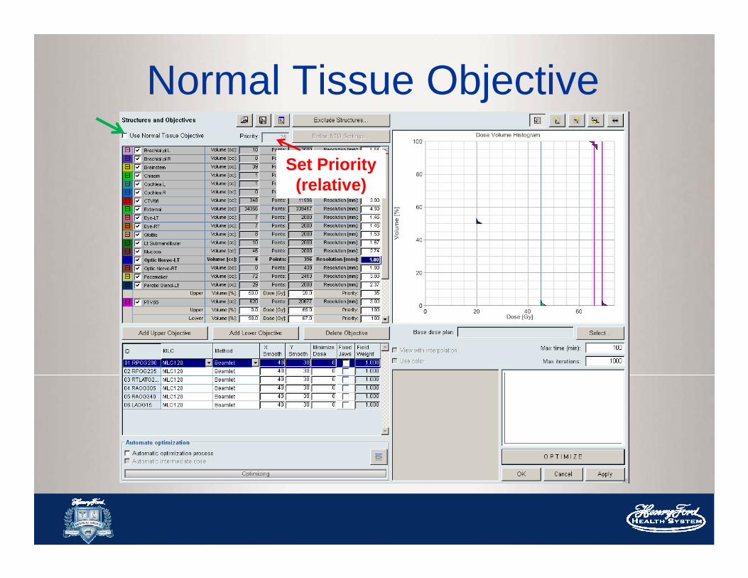
Normal Tissue Objective
Set Priority (relative)
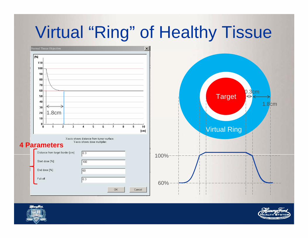
Virtual “Ring” of Healthy Tissue
1.8cm
0.3cm
1.8cmTarget
Virtual Ring
100%
60%
4 Parameters
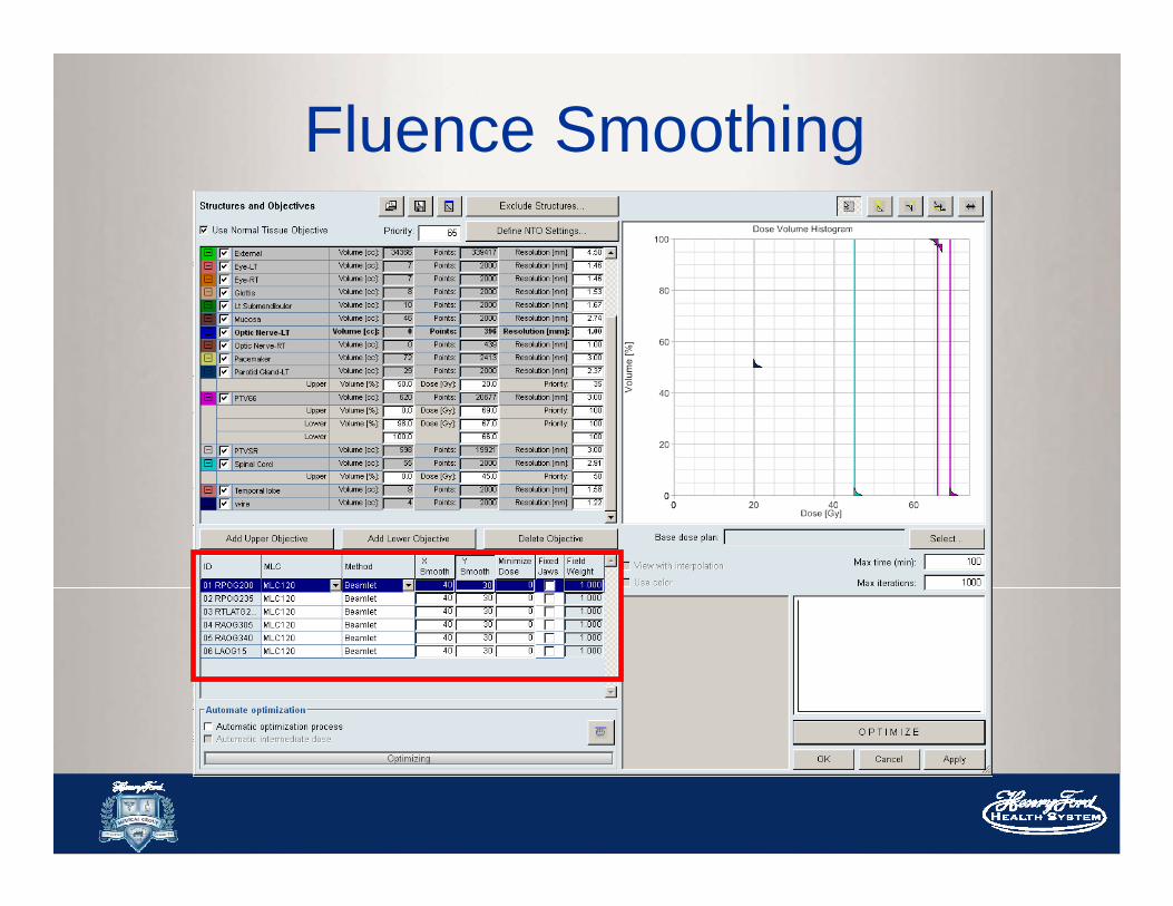
Fluence Smoothing

High frequency noise is produced during optimization Smoothing helps to remove noise Noise can increase modulation, increase
MU, and strain MLC delivery
Fluence Smoothing

Too little smoothing- Fluence is too noisy- Increase MU- Decrease deliverability
of the plan
Too much smoothing- Affect your dose
gradients- Effect dose to OARs- Slow dose fall off to
normal tissues
These numbers are weightings similar to “Priority” (relative to
PTV)

The Optimization ProcessPost-Process Structures:
Smooth, Create Opt structures, PRVs, PTV
expansions
Choose Beam Geometry: BAO/ templates
Physician’s Prescription Define Optimization Objectives
Optimize Fluence
Calculate Leaf Motions
Evaluate Dose Distributions

Optimization: The optimizerDose Volume Optimizer (DVO)- Gradient based method- Try to minimize the overall “penalty”
Gradient methods are quick!
However, you may get stuck in a local minimum
These are often clinically acceptable solutions
https://www.boundless.com/calculus/derivatives-and-integrals/derivatives--2/derivatives-and-rates-of-change/
Penalty Function HUGE animation goes here
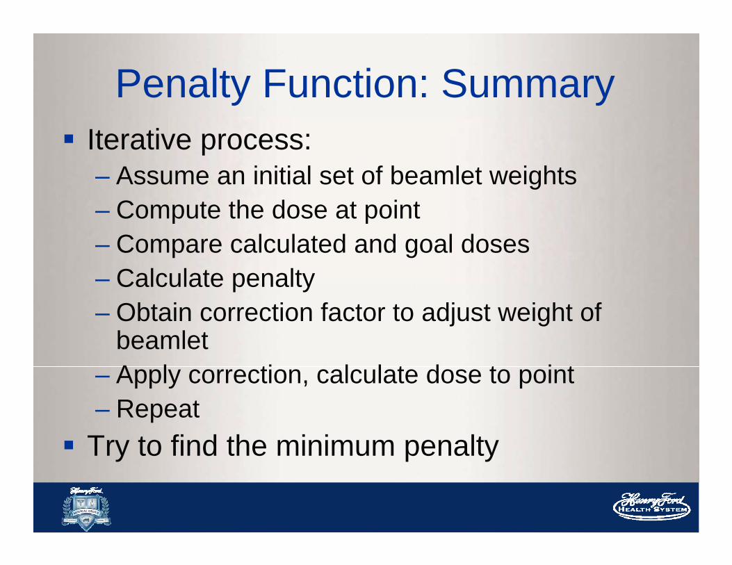
Iterative process:– Assume an initial set of beamlet weights– Compute the dose at point– Compare calculated and goal doses– Calculate penalty– Obtain correction factor to adjust weight of
beamlet– Apply correction, calculate dose to point – Repeat
Try to find the minimum penalty
Penalty Function: Summary
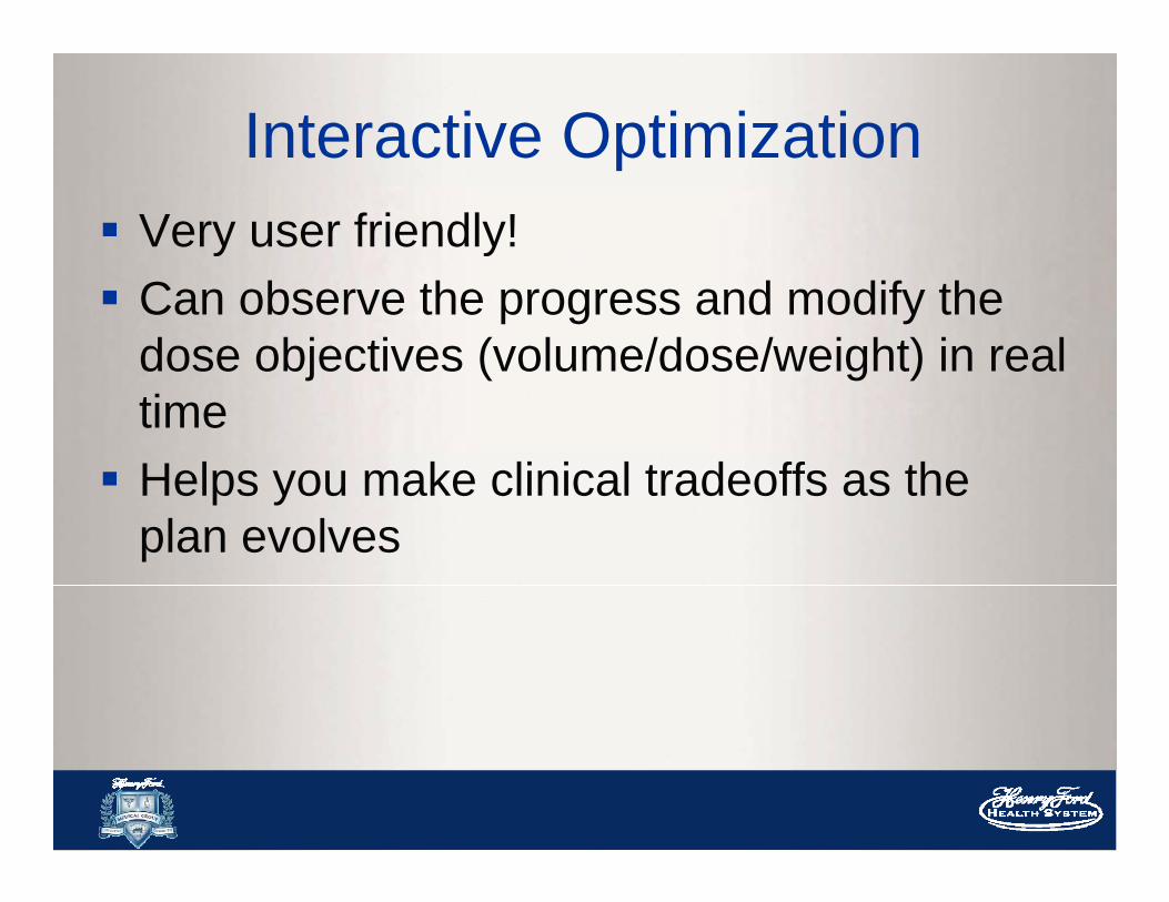
Interactive Optimization Very user friendly! Can observe the progress and modify the
dose objectives (volume/dose/weight) in real time Helps you make clinical tradeoffs as the
plan evolves
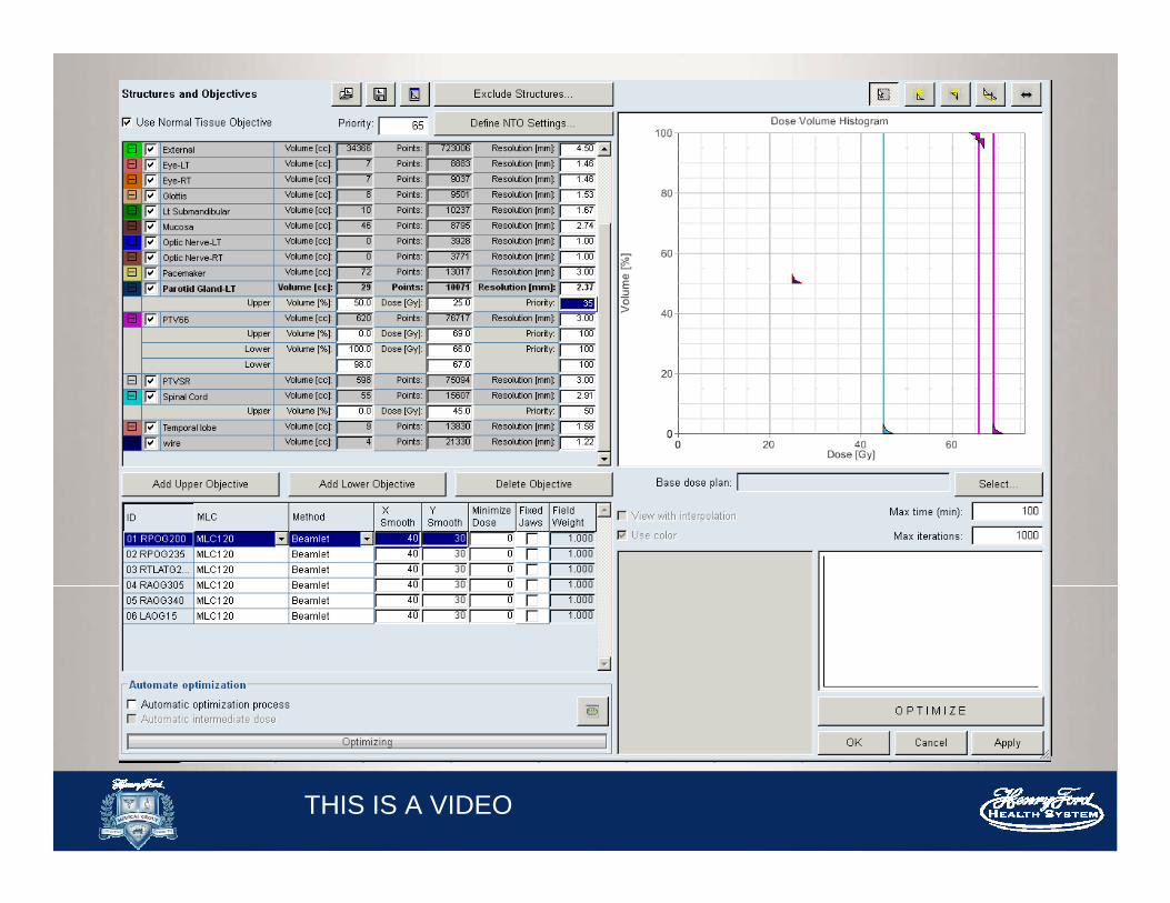
THIS IS A VIDEO
The Optimization ProcessPost-Process Structures:
Smooth, Create Opt structures, PRVs, PTV
expansions
Choose Beam Geometry: BAO/ templates
Physician’s Prescription Define Optimization Objectives
Optimize Fluence
Calculate Leaf Motions
Evaluate Dose Distributions

Leaf Motion CalculatorNow that we have this optimal fluence we need to deliver this fluence using the MLCs
-Takes into account of dosimetric characteristics of the MLC (transmission, DLG) measured by a physicist during commissioning
-Mechanical limits of the MLC (speed and leaf span)
-Calculates the actual fluence that will be delivered to the patient
-Calculates Monitor Units
“optimal” “actual”

Different MLC delivery methods
Leaf Motion Calculator
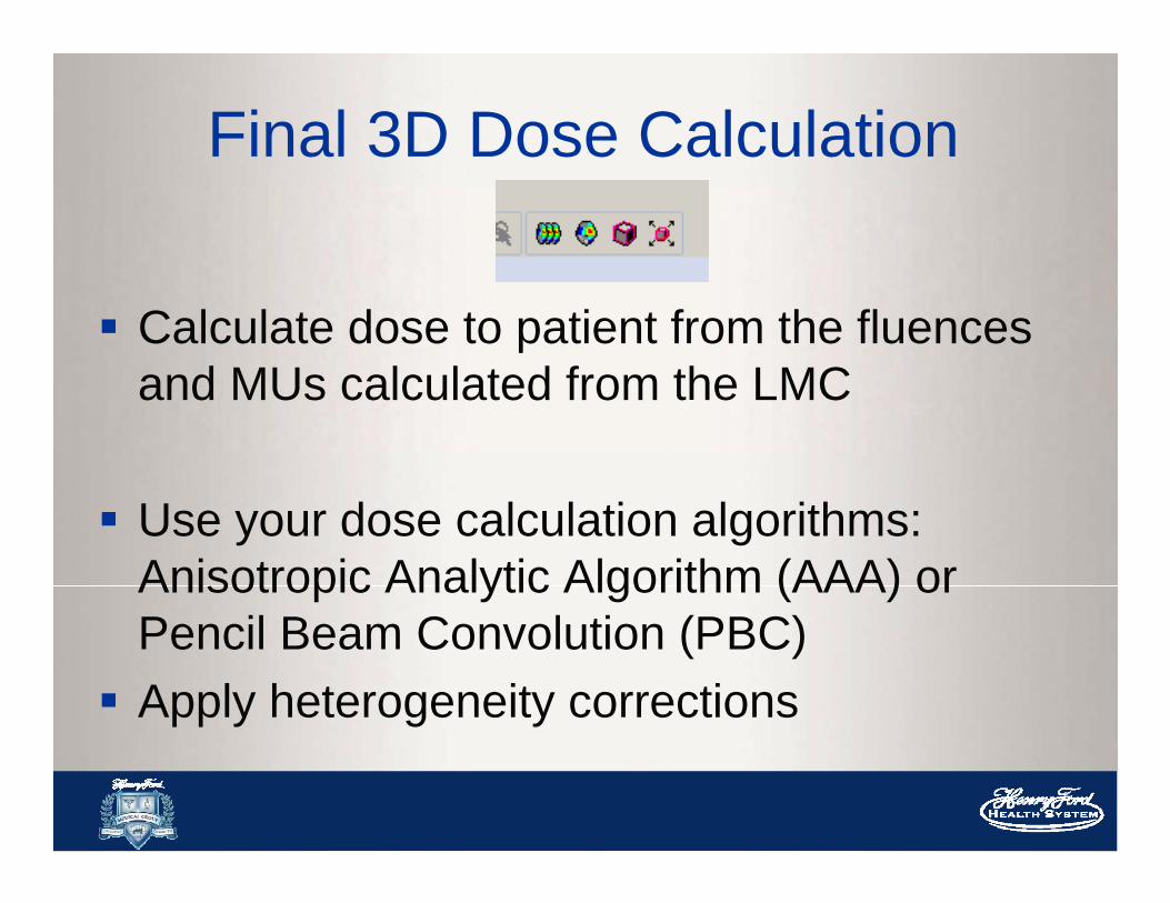
Final 3D Dose Calculation
Calculate dose to patient from the fluencesand MUs calculated from the LMC
Use your dose calculation algorithms: Anisotropic Analytic Algorithm (AAA) or Pencil Beam Convolution (PBC) Apply heterogeneity corrections
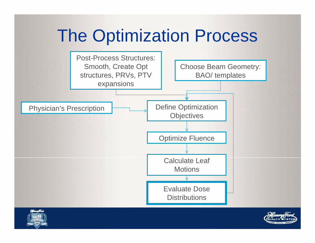
The Optimization ProcessPost-Process Structures:
Smooth, Create Opt structures, PRVs, PTV
expansions
Choose Beam Geometry: BAO/ templates
Physician’s Prescription Define Optimization Objectives
Optimize Fluence
Calculate Leaf Motions
Evaluate Dose Distributions
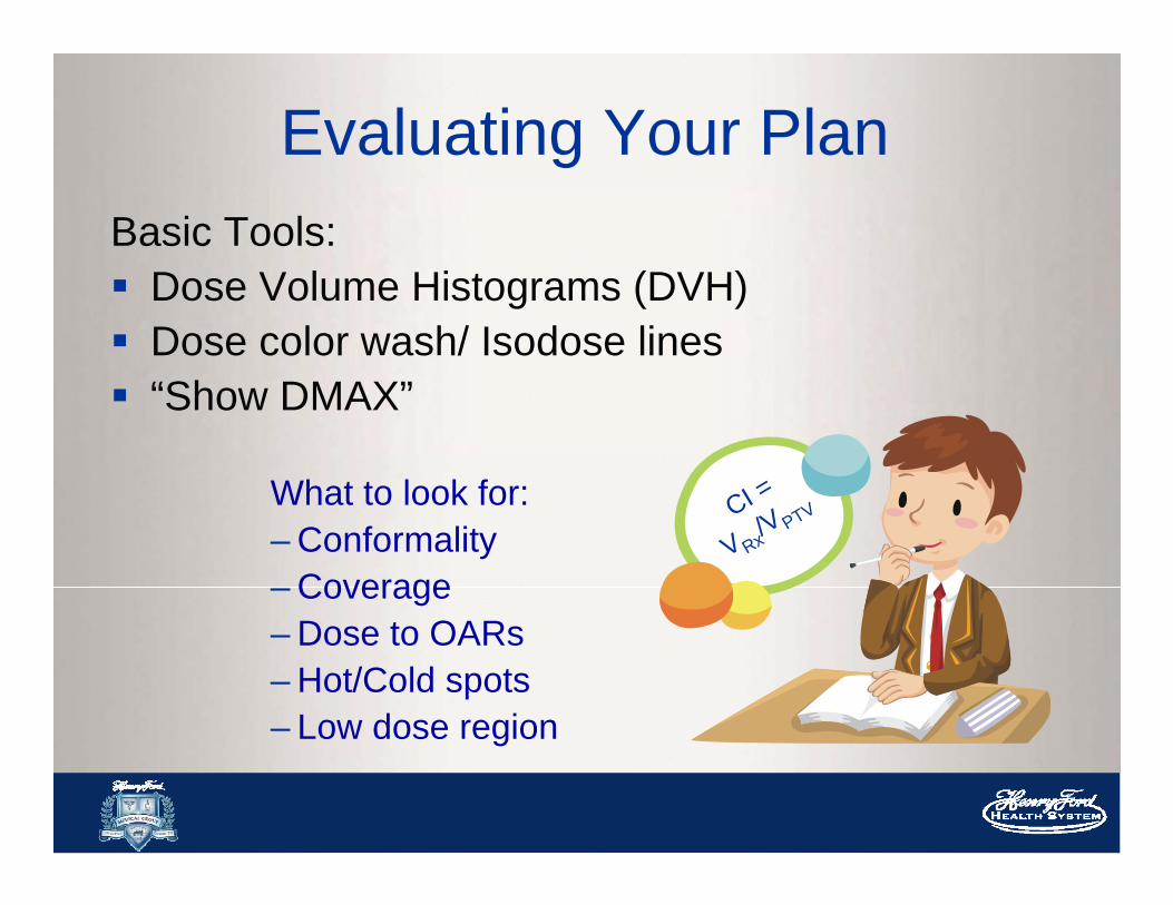
Evaluating Your PlanBasic Tools: Dose Volume Histograms (DVH) Dose color wash/ Isodose lines “Show DMAX”
What to look for:– Conformality– Coverage– Dose to OARs– Hot/Cold spots– Low dose region
CI =
V Rx/V PTV

Glioma: PTV46
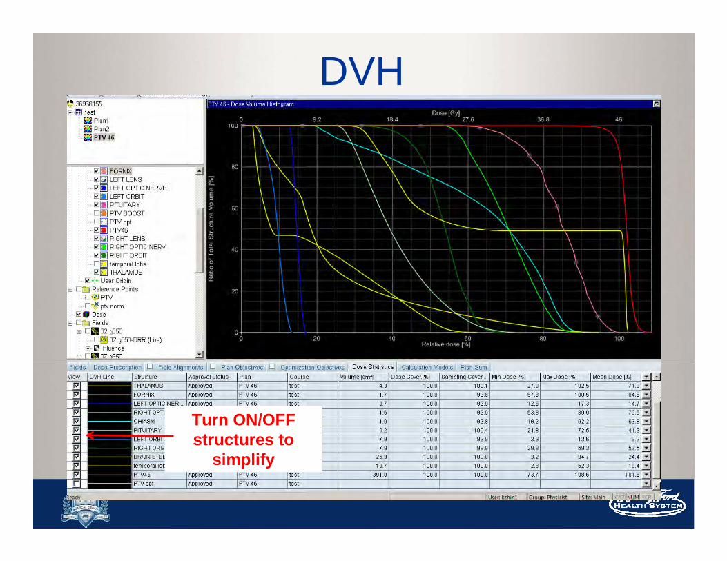
DVH
Turn ON/OFF structures to
simplify

PTV Coverage
95% of the PTV volume
RECEIVES
98.5% of the Prescription
Dose

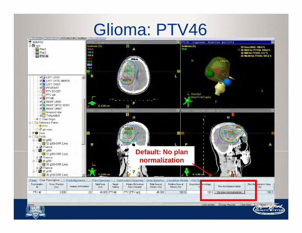
Glioma: PTV46
Default: No plan normalization

Normalization Methods
- Some methods are more suitable for 3D, such as “points” or isocenter
- Easy normalization by scaling
-Or according to physician’s Rx or preference

95% of the PTV volume
RECEIVES
100% of the Prescription
Dose

Remember your OAR doses will
scale up as well!


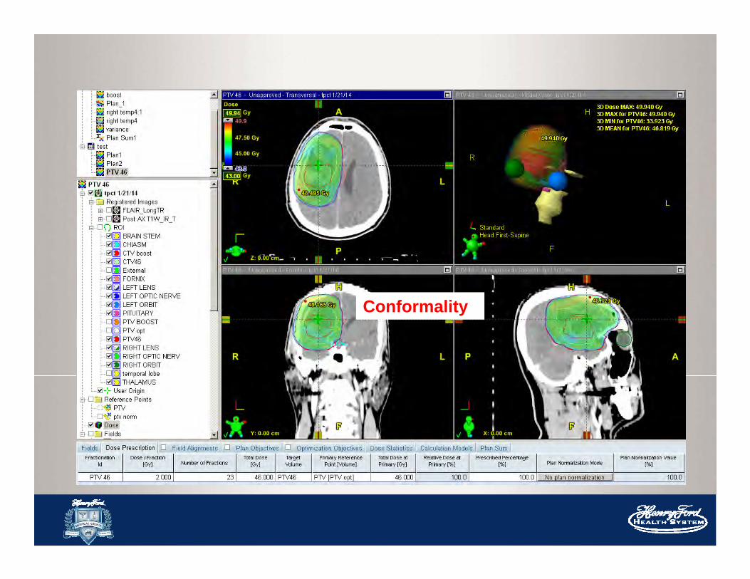
Conformality


Advanced Techniques
SIB:Simultaneous
Integrated Boost
Different volumes going
to different doses

Thank you!

And, Thank you to all the dosimetrists!