improving temperature measurement to optimize inventory control
TRANSCRIPT
1
Improving Temperature Measurement to Optimize
Inventory Control and Custody Transfer Systems
The measurement of temperature is critical in the determination of the true volume ofproduct in a hydrocarbon storage tank and how that may be improved with the use oftrue averaging sensors or multiple-spot temperature sensors. Simple temperaturemeasurement has been performed for many years, in ways as simple as glassthermometers hung in a tank or as sophisticated as a tank gauging system mounted onthe tank roof.
Temperature has the most significant effect on the accurate determination of liquidquantities when correcting to standard conditions for custody transfer and inventorycontrol purposes. “An error in the determination of temperature may result in eitherover-or understatement of the quantity, regardless of the accuracy obtained in gaugingthe liquid’s level”.
The accurate measurement of temperature is a critical factor in determining the volumeof the contents of a tank and the transfer of the material out of the tank. “A change of 1deg. F in the product temperature can allow an error of 120 barrels, in a tank ofapproximately 300,000 barrels”. At the current price of petroleum, an error of thatmagnitude could be significant. In the past, a single thermometer inserted into the tankswas sufficient for monitoring the temperature of the tank. Now, that method is decidedlynot sufficient according to new standards from the American Petroleum Institute. Oiltends to stratify as it settles in the tank, which is compounded as product is moved inand out the tank. Because of this phenomenon, a more reliable means of measuringthe temperature in the tank is required. The only way to get the correct reading of theactual temperature in the tank is to use an averaging temperature sensor. Use of thisdevice will allow temperature measurements to be taken at various heights in the tank,thereby negating the effects of product stratification.
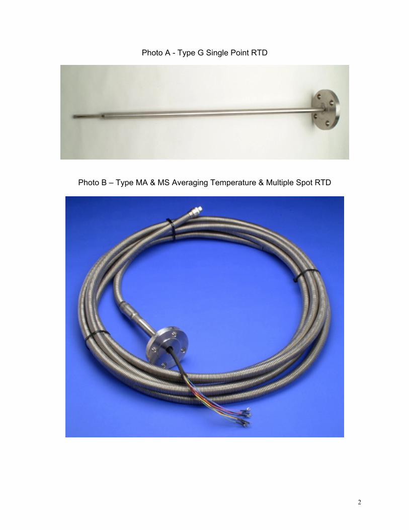
“For custody transfer temperature measurement, local direct-reading thermometers arenot recommended. Copper or platinum temperature elements bulbs, that is resistancetemperature detectors (RTDs) are normally used for this application.” Choice of themethod of temperature measurement, e.g. single-point, multiple-point or averaging,should be based on the desired accuracy requirements and the type of material in thestorage tank. (See photos A & B).
2
Photo A - Type G Single Point RTD
Photo B – Type MA & MS Averaging Temperature & Multiple Spot RTD
3
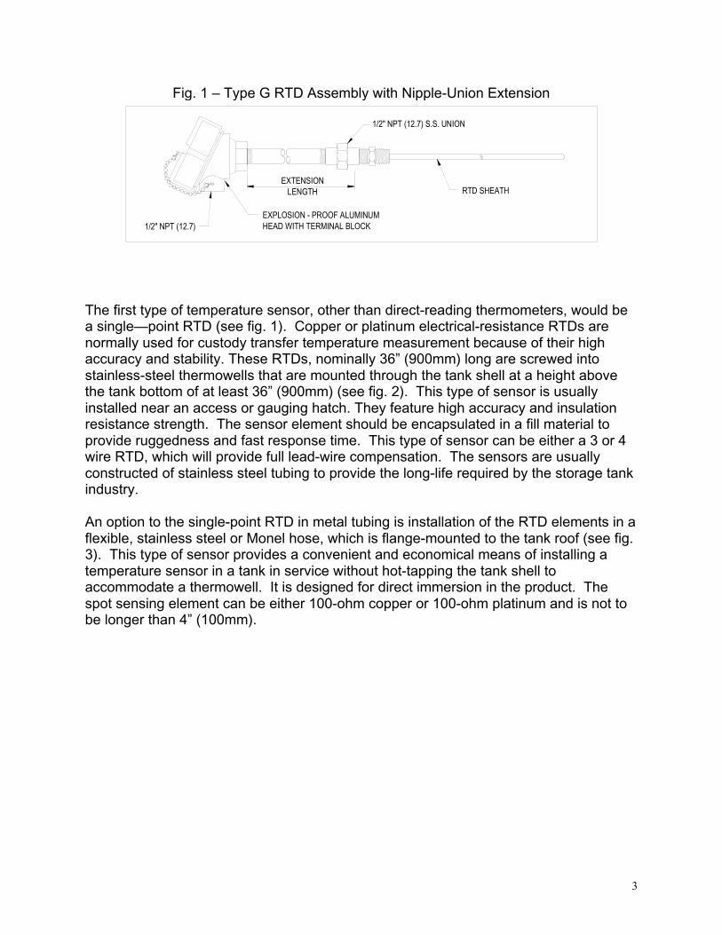
Fig. 1 – Type G RTD Assembly with Nipple-Union Extension
1/2" NPT (12.7) S.S. UNION
EXTENSION LENGTH RTD SHEATH
EXPLOSION - PROOF ALUMINUM HEAD WITH TERMINAL BLOCK1/2" NPT (12.7)
The first type of temperature sensor, other than direct-reading thermometers, would bea single—point RTD (see fig. 1). Copper or platinum electrical-resistance RTDs arenormally used for custody transfer temperature measurement because of their highaccuracy and stability. These RTDs, nominally 36” (900mm) long are screwed intostainless-steel thermowells that are mounted through the tank shell at a height abovethe tank bottom of at least 36” (900mm) (see fig. 2). This type of sensor is usuallyinstalled near an access or gauging hatch. They feature high accuracy and insulationresistance strength. The sensor element should be encapsulated in a fill material toprovide ruggedness and fast response time. This type of sensor can be either a 3 or 4wire RTD, which will provide full lead-wire compensation. The sensors are usuallyconstructed of stainless steel tubing to provide the long-life required by the storage tankindustry.
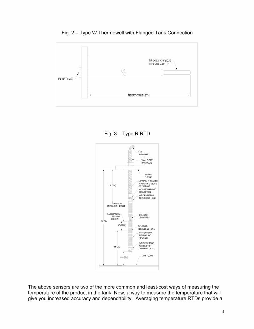
An option to the single-point RTD in metal tubing is installation of the RTD elements in aflexible, stainless steel or Monel hose, which is flange-mounted to the tank roof (see fig.3). This type of sensor provides a convenient and economical means of installing atemperature sensor in a tank in service without hot-tapping the tank shell toaccommodate a thermowell. It is designed for direct immersion in the product. Thespot sensing element can be either 100-ohm copper or 100-ohm platinum and is not tobe longer than 4” (100mm).
4
Fig. 2 – Type W Thermowell with Flanged Tank Connection
INSERTION LENGTH
TIP O.D. 0.475" (12.1)TIP BORE 0.281" (7.1)
1/2" NPT (12.7)
Fig. 3 – Type R RTD
MATINGFLANGE
RTD LEADWIRES
TANK ENTRY HARDWARE
WELDED FITTING TO FLEXIBLE HOSE
ELEMENT LEADWIRES
3/4" (19) I.D. FLEXIBLE SS HOSE
WELDED FITTING WITH 3/4" NPT THREADED PLUG
TANK FLOOR
TEMPERATURE SENSING
ELEMENT"H" DIM
4" (101.6)
"M" DIM
6" (152.4)
3/4" NPT THREADED CONNECTION
3/4" NPSM THREADED PIPE WITH 12" (304.8) OF THREADS
Ø1.05 (26.7) DIA. (NOMINAL 3/4" PIPE SIZE)
10" (254)
MAXIMUM PRODUCT HEIGHT
The above sensors are two of the more common and least-cost ways of measuring thetemperature of the product in the tank, Now, a way to measure the temperature that willgive you increased accuracy and dependability. Averaging temperature RTDs provide a
5
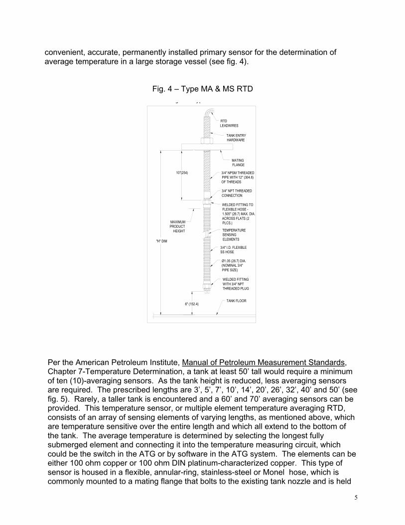
convenient, accurate, permanently installed primary sensor for the determination ofaverage temperature in a large storage vessel (see fig. 4).
Fig. 4 – Type MA & MS RTD
3/4" NPT THREADED CONNECTION
WELDED FITTING TO FLEXIBLE HOSE - 1.505" (26.7) MAX. DIA. ACROSS FLATS (2 PLCS.)
WELDED FITTING WITH 3/4" NPT THREADED PLUG
TANK FLOOR
3/4" I.D. FLEXIBLE SS HOSE
"H" DIM
6" (152.4)
TEMPERATURE SENSING ELEMENTS
10"(254)
MAXIMUM PRODUCT
HEIGHT
Ø1.05 (26.7) DIA. (NOMINAL 3/4" PIPE SIZE)
3/4" NPSM THREADED PIPE WITH 12" (304.8) OF THREADS
TANK ENTRY HARDWARE
g yp
RTD LEADWIRES
MATINGFLANGE
Per the American Petroleum Institute, Manual of Petroleum Measurement Standards,Chapter 7-Temperature Determination, a tank at least 50’ tall would require a minimumof ten (10)-averaging sensors. As the tank height is reduced, less averaging sensorsare required. The prescribed lengths are 3’, 5’, 7’, 10’, 14’, 20’, 26’, 32’, 40’ and 50’ (seefig. 5). Rarely, a taller tank is encountered and a 60’ and 70’ averaging sensors can beprovided. This temperature sensor, or multiple element temperature averaging RTD,consists of an array of sensing elements of varying lengths, as mentioned above, whichare temperature sensitive over the entire length and which all extend to the bottom ofthe tank. The average temperature is determined by selecting the longest fullysubmerged element and connecting it into the temperature measuring circuit, whichcould be the switch in the ATG or by software in the ATG system. The elements can beeither 100 ohm copper or 100 ohm DIN platinum-characterized copper. This type ofsensor is housed in a flexible, annular-ring, stainless-steel or Monel hose, which iscommonly mounted to a mating flange that bolts to the existing tank nozzle and is held
6
vertical in the tank product with an anchor weight of approximately 25 lbs. If turbulenceor stirring is occurring in the tank, whereby the anchor would not keep the sensor stable,then an alternate positioning technique would be to install the temperature sensor in aperforated, stilling pipe. This is a pipe with holes along the axis, secured at the top ofthe tank and bottom of the tank, that allows the product in flow in and around thetemperature sensor, thereby giving an accurate temperature measurement of theproduct.
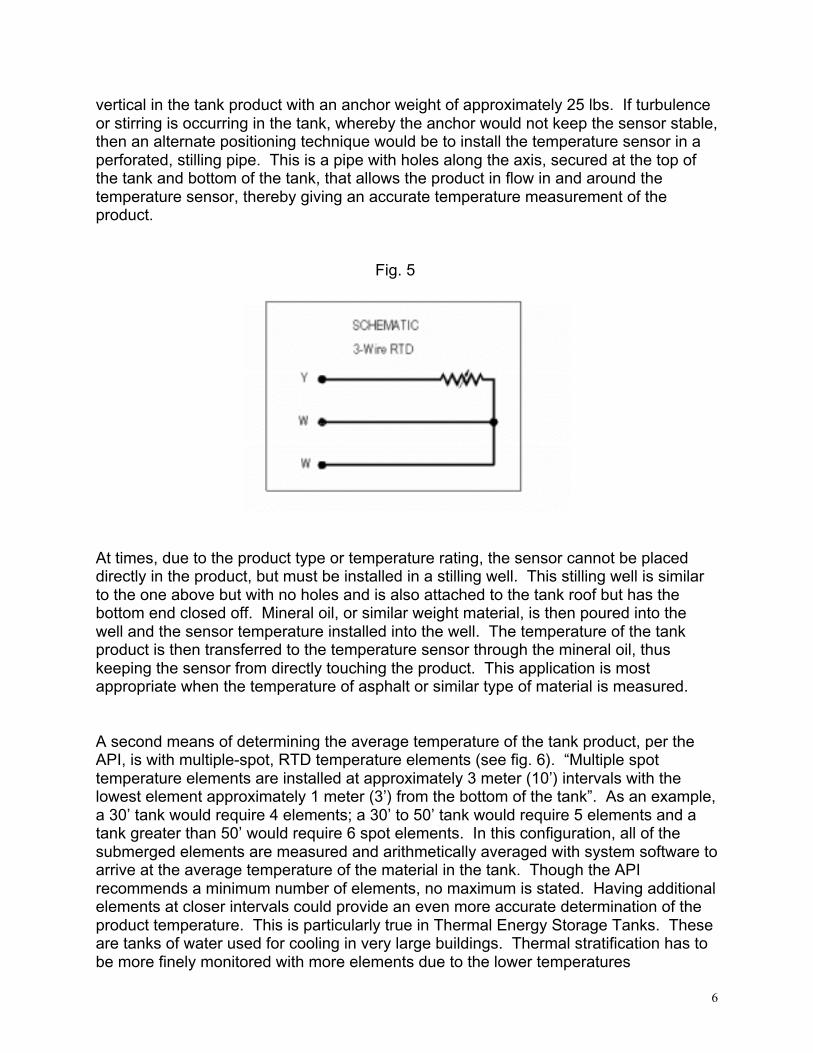
Fig. 5
At times, due to the product type or temperature rating, the sensor cannot be placeddirectly in the product, but must be installed in a stilling well. This stilling well is similarto the one above but with no holes and is also attached to the tank roof but has thebottom end closed off. Mineral oil, or similar weight material, is then poured into thewell and the sensor temperature installed into the well. The temperature of the tankproduct is then transferred to the temperature sensor through the mineral oil, thuskeeping the sensor from directly touching the product. This application is mostappropriate when the temperature of asphalt or similar type of material is measured.
A second means of determining the average temperature of the tank product, per theAPI, is with multiple-spot, RTD temperature elements (see fig. 6). “Multiple spottemperature elements are installed at approximately 3 meter (10’) intervals with thelowest element approximately 1 meter (3’) from the bottom of the tank”. As an example,a 30’ tank would require 4 elements; a 30’ to 50’ tank would require 5 elements and atank greater than 50’ would require 6 spot elements. In this configuration, all of thesubmerged elements are measured and arithmetically averaged with system software toarrive at the average temperature of the material in the tank. Though the APIrecommends a minimum number of elements, no maximum is stated. Having additionalelements at closer intervals could provide an even more accurate determination of theproduct temperature. This is particularly true in Thermal Energy Storage Tanks. Theseare tanks of water used for cooling in very large buildings. Thermal stratification has tobe more finely monitored with more elements due to the lower temperatures

7
experienced with thermal energy storage. A second benefit of the multiple spot systemis the ability to use the spots to provide the vertical profile of the temperature. The spotelements can be either 100-ohm copper or 100 ohm DIN platinum, depending on theATG used. One additional benefit of multiple spot elements is that the ullagetemperature in the tank, if required, can also be measured with one of the spot elementsnot in the product. This would allow the temperature of the vapor space to be known, ifrequired.
Fig. 6 – Schematic – Multiple Spot Elements
TA
NK
HE
IGH
T
1 2 3 4 5 6
(Leadwire colors dependent upon no. of elements)
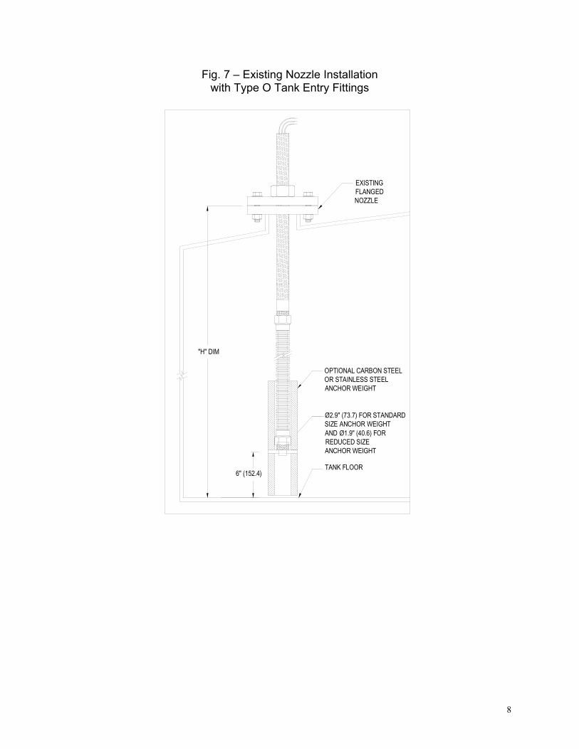
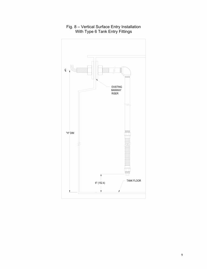
A third means of measuring the average temperature in the tank, per the API, is with amultiple spot, thermocouple system. Each thermocouple, like the multiple spot RTDelement, measures the product temperature at a specific point. A thermocouple arraywill usually have at least 15, evenly spaced spots. An average temperature of theproduct is made by arithmetically averaging all the spots submerged by the product.Additionally, individual spots can be used to determine a tank temperature profile. A100-ohm, platinum RTD is usually installed in the tip of the hose as a reference point forthe lowest point of temperature measurement in the tank. Individual spots notimmersed in the product can be used to measure the ullage temperature of the tank.Knowing the temperature of the vapor space can be useful information, if required.Though copper or platinum RTDs are normally used for custody transfer, thermocoupleassemblies are gaining acceptance. Though it would be preferable to design thetemperature sensors into the initial tank design, all of the above type of sensors can beadded to the tank either before, during or after construction of the tank.Due to the fact that the averaging sensor is installed through a single nozzle on the tankroof, maintenance is very easy. If a sensor should need to be replaced, the flange isunbolted and the sensor is lifted straight out of the tank (see fig. 7 and fig. 8).
8
Fig. 7 – Existing Nozzle Installationwith Type O Tank Entry Fittings
OPTIONAL CARBON STEEL OR STAINLESS STEEL ANCHOR WEIGHT
Ø2.9" (73.7) FOR STANDARD SIZE ANCHOR WEIGHT AND Ø1.9" (40.6) FOR REDUCED SIZE ANCHOR WEIGHT
EXISTING FLANGED NOZZLE
TANK FLOOR6" (152.4)
"H" DIM
9
Fig. 8 – Vertical Surface Entry InstallationWith Type 6 Tank Entry Fittings
TANK FLOOR6" (152.4)
"H" DIM
EXISTING MANWAY RISER
CL
10
Advantages and disadvantages of different temperature measurement equipment
Averaging RTDs versus spot RTDs versus Thermocouples
• Averaging RTDs provide a more accurate means of measuring the averagetemperature in an oil storage tank than any other means
• Obtaining a tank temperature profile of the product in the tank can more accuratelybe determined with a spot temperature array
• The individual spot temperature elements have the ability to give a discrete point oftemperature measurement in the product
• Spot temperature sensors can give a point of measurement in the ullage of the tank
• Each spot measurement is an individual 3 or 4-wire RTD
• Average temperature elements have a common ground
• Averaging elements extend to the bottom of the tank
• Multiple spot elements begin at the top of the tank
• Averaging RTDs negate the effect of thermal stratification
• Multiple spot RTD can produce a tank temperature profile
• The tank gauging system selects the longest, fully submerged averaging element todetermine the average temperature
• All submerged spot elements are measured and arithmetically averaged todetermine average temperature
• RTDs are repeatable and stabile and are the primary interpolation instrument usedby the NIST, (National Institute of Standards and Technology) additionally drift istypically less than 0.1 ºC/year
• The voltage drop across an RTD provides a much larger output than a thermocouple
• Copper and platinum RTDs produce a more linear response than thermocouples
• Thermocouples can withstand higher temperatures than RTDs, as high as 1800 ºC
• Thermocouples are simpler devices than RTDs, which makes them inherently moreresistant to shock and vibration
• Thermocouples have a faster time response and lower mass than RTDs

11
New developments
Water Bottom Monitor
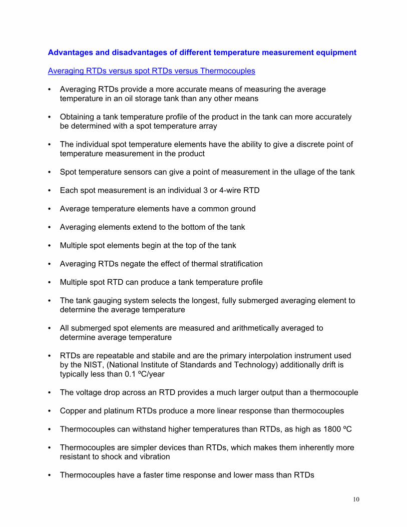
In addition to providing a highly accurate and dependable average temperature of thetank contents, the Combination Averaging Temperature RTD and Water Bottom Monitoralso provides a continuous indication of water/oil interface (see fig. 9). This informationcan then be factored into the net barrel calculation along with temperature correction.Additionally, the information can be utilized to schedule water draw-off activities. Thewater interface-measuring portion of the assembly utilizes a capacitance probe withintrinsically safe circuitry to determine the interface level between the water and productin the tank. The transmitter is microprocessor-based and can be supplied with a 4 to 20mA or HART output. The Water Bottom Monitor may also be supplied withouttemperature sensing elements, if all that is required is to indicate the oil/water interface.(See photo C).
Fig. 9 – Type MWR
WELDED FITTING WITH 3/4" NPT THREADED PLUG
3/4" NPT THREADED CONNECTION
WELDED FITTING TO FLEXIBLE HOSE
TANK FLOOR
3/4" I.D. FLEXIBLE SS HOSE"H" DIM
TEMPERATURE SENSING ELEMENTS
CAPACITANCE PROBE
CAPACITANCE TRANSMITTER
WATERTIGHT CAPACITANCE PROBE CONNECTION
MATINGFLANGE
TANK ENTRY HARDWARE
RTDLEADWIRES
12
Photo C – Capacitance Probe with Transmitter
Plug-and-Play
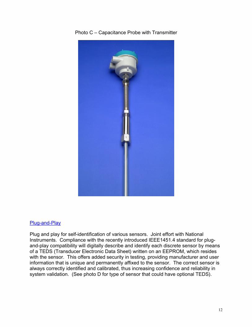
Plug and play for self-identification of various sensors. Joint effort with NationalInstruments. Compliance with the recently introduced IEEE1451.4 standard for plug-and-play compatibility will digitally describe and identify each discrete sensor by meansof a TEDS (Transducer Electronic Data Sheet) written on an EEPROM, which resideswith the sensor. This offers added security in testing, providing manufacturer and userinformation that is unique and permanently affixed to the sensor. The correct sensor isalways correctly identified and calibrated, thus increasing confidence and reliability insystem validation. (See photo D for type of sensor that could have optional TEDS).
13
Photo D – RTD Assembly with TEDS Option
The question has been asked about other uses to which this type of technology couldbe applied. We submit that this type of sensor can be used in any type of liquid, as longas it is compatible with stainless steel or Monel. We have supplied multiple-spotaveraging sensors to very disparate applications, such as a high-purity, liquid sodiumstorage for Dow Chemical and wine fermentation tank for Gallo Winery.
Thermal Energy Storage (TES)
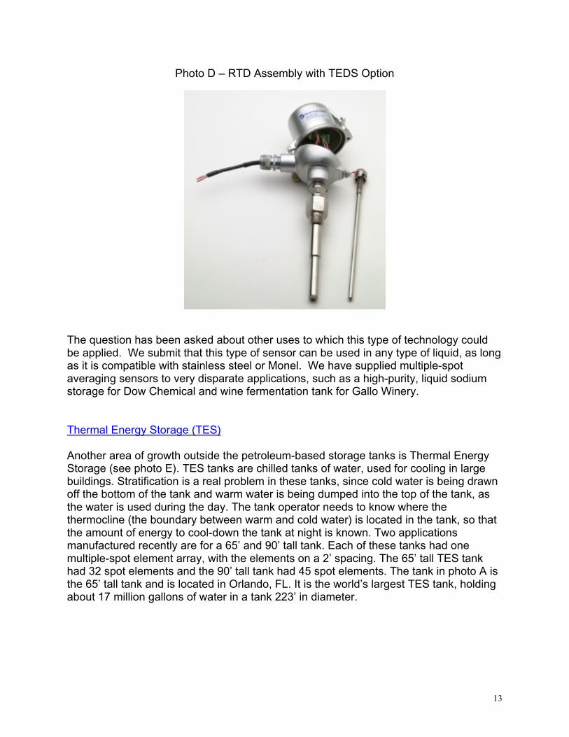
Another area of growth outside the petroleum-based storage tanks is Thermal EnergyStorage (see photo E). TES tanks are chilled tanks of water, used for cooling in largebuildings. Stratification is a real problem in these tanks, since cold water is being drawnoff the bottom of the tank and warm water is being dumped into the top of the tank, asthe water is used during the day. The tank operator needs to know where thethermocline (the boundary between warm and cold water) is located in the tank, so thatthe amount of energy to cool-down the tank at night is known. Two applicationsmanufactured recently are for a 65’ and 90’ tall tank. Each of these tanks had onemultiple-spot element array, with the elements on a 2’ spacing. The 65’ tall TES tankhad 32 spot elements and the 90’ tall tank had 45 spot elements. The tank in photo A isthe 65’ tall tank and is located in Orlando, FL. It is the world’s largest TES tank, holdingabout 17 million gallons of water in a tank 223’ in diameter.
14
Photo E – Inside Thermal Energy Storage Tank
Conclusion
Temperature can be measured in many ways, with many different types of devices. Formost of our customer’s applications, we submit that the best way to measure theaverage temperature is with an averaging temperature or multiple-spot type sensorarray. This will give you the most reliable and consistent measurement of the averagetemperature in the tank.
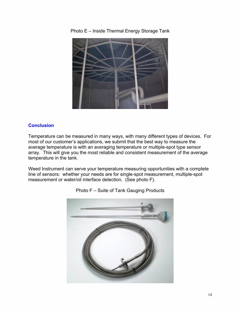
Weed Instrument can serve your temperature measuring opportunities with a completeline of sensors: whether your needs are for single-spot measurement, multiple-spotmeasurement or water/oil interface detection. (See photo F).
Photo F – Suite of Tank Gauging Products

15
References:
“Tank Temperature Measurement Using Averaging Techniques”, John Pritchard, 1994
“Manual of Petroleum Measurement Standards”, Chapter 7 – TemperatureDetermination, June 2001
“Manual of Petroleum Measurement Standards, Chapter 3-Tank Gauging, Dec. 1994
Weed Instrument Tank Temperature Measurement catalog