improving spark-ignited engines efficiency by heat energy...
TRANSCRIPT

64 COMBUSTION ENGINES, No. 2/2015 (161)
1. IntroductionSince first emission norm were introduced there is continu-
ous global process to create and manufacture internal combus-tion engines which will emit less and less emissions. Process is handled on many different levels: from parliament decisions to local harbours regulations. The form how it is passed on engine makers can also differ: from fiscal benefits to encourage users having environment friendly vehicles or vessels, to very strict rules about permits for registration or zone entry given only to the clean ones. This is main driving factor for various R&D activities which result with technologies that provide fewer emissions for exactly same daily use of the engine as before.
Recently very common procedure for shipping and ferry lines is to convert engine and fuel system to use LNG (lique-fied natural gas) instead of much cheaper typical marine HFO (heavy fuel oil). By this modification there is less NOx, SOx, particulates and finally also CO2 emitted by the vessel. Other example are methods to improve engine efficiency, so for the same work delivered by engine less fuel will be required and then less combustion products will be created. It can be observed for automotive engines as downsizing. Older naturally aspirated engines with high displacement volume are replaced with modern turbocharged or supercharged engines that can deliver same power using much smaller displacement, some of them with the cylinder-on-demand – the system that can instantly switch on or off any cylinder accordingly to current engine power demand. Additionally, these modern engines have much better torque distribution over their speed range. The opposite development direction can be observed for stationary and marine engines. These engines are getting bigger and the efficiency improvement can be gained thanks to more optimal and colder combus-tion process as well as by higher engine boost. Change of BMEP (break mean effective pressure) from 10 bar to 20 bar will result with engine efficiency change from about 38% to about 46% [1, 2, 4].
There is however limit for efficiency that can be reached. For the theoretical spark-ignited engine the efficiency ƞ
Marek SUTKOWSKI
Improving spark-ignited engines efficiency by heat energy recovery systemThe current trends in regulations changes focus more and more on emissions reduction. Earlier environment protec-
tion mechanisms covering emissions limits of particulates, nitrogen oxides, sulphur oxides and carbon monoxide were recently extended also to cover carbon dioxide emissions. One way to reduce carbon dioxide emission is the improvement of the efficiency of a powertrain system or main driver efficiency. This paper explains main limitations for efficiency improvement when conventional methods are used. The effective heat energy recovery system principles and its techni-cal specification are described including its control principles. System was initially tested in the engine laboratory and experience from the laboratory tests is included in the paper. After successful and promising laboratory tests the solution was transferred to commercial operation which covered already period of more than 2 years. Statistics and operational data from commercial operation is shown with relevant examples of various operational modes. At the end of the paper simple feasibility study is shown. Alternative applications with basic evaluation of their feasibility and efficiency improve-ment potential are included in this paper as well.Key words: heat recovery system, turbo-compound
depends only on its compression ratio e and working fluid properties – adiabatic coefficient k:
h = 1–(1/(ek–1)) (1)
The real engine is not that efficient due to many de-viations from ideal cycle. First of all real fluid has lower k-coefficient, then there is unburnt fuel, friction losses, heat losses from flame to surrounding walls, flow losses and finally slow and unstable combustion. Additionally knock combustion phenomenon is strongly limiting engine com-pression ratio e. Modern technologies allow to reduce impact of many of listed factors but still there will be a gap between theoretical efficiency and real efficiency. Knock combustion can be avoided with modern high-pressure direct-injection fuel systems but only part of gained improvements will be utilised as such solutions result in less stable combustion and higher amount of unburnt fuel. Other possible improvements are listed in the Table 1, together with their potential impact on engine efficiency.
2. Heat energy recovery systemQuite a big amount of fuel energy is not used for ef-
fective work and remains as a heat in exhaust gas. For typical automotive naturally aspirated engines about 33% of fuel energy escapes through the exhaust system. Part of that energy can be recovered by turbocharger to increase engine power but even for big high-boosted stationary engine unused part of fuel energy will be still over 25%. In cogeneration applications exhaust heat is very valuable source of energy which can be used to generate hot water or steam. Steam then can be utilised to generate electricity or mechanical power with a steam turbine. There are available many different examples of combined cycle power plants having total efficiency of electricity production close even to 60%. Unfortunately such solutions are possible only for power generation or marine applications, leaving automo-tive engines again with low efficiency. Another solution known for decades is turbo-compound system where there
PTNSS-2015-207
Article citation info: SUTKOWSKI M. Improving spark-ignited engine efficiency by heat energy recovery system. Combustion Engines. 2015, 161(2), 64-67. ISSN 2300-9896.

65COMBUSTION ENGINES, No. 2/2015 (161)
is an exhaust gas driven turbine which can then deliver recovered power to the engine shaft. Recently introduced new regulations in Formula 1 motorsport require all engine suppliers to include turbo-compound system. In Formula 1 applied solution the exhaust gas is first passing turbocharger turbine and then is fed to turbo-compound system. Energy recovered from exhaust can be stored in electrical form and can be used during car acceleration, if needed.
Turbo-compound systems can be applied also for regular automotive engines, truck engines, marine engines and en-gines used for power generation. In this last application ETC (electric turbo-compound) is most commonly used as there is no need to feed turbo-compound power to engine shaft and ETC power can be directly used as electricity. The typical ETC system is very similar to automotive solutions with its own additional turbine after the turbocharger to recover a portion of the still available waste heat energy from the engine exhaust stream. The turbine uses fixed nozzle guide vanes which can be altered to optimise the match to each application. The turbine is directly coupled to a high speed and high efficiency alternator and the combined unit is usually termed a TG (turbo-generator). The TG in ETC system has its own self-contained oil system, providing both lubrication and cooling. The existing turbocharger is replaced with a new high efficiency model that is correctly matched to the TG downstream to optimise energy recovery. A separate Power Electronics panel provides all required control functions and conversion of the alternator output to electrical grid quality 3 phase power with frequency of 50 Hz or 60 Hz, as required by local electrical grid. The ETC system can be integrated on both open and containerised engines, it has a compact footprint and system maintenance intervals are designed to align with engine maintenance schedules. The ETC working principle is shown on Fig. 1.
3. Technology benefitsThe typical ETC system is primarily for use on continu-
ous engine load applications, both diesel and gas fuelled engines ranging from 0.2 MW to 4 MW. The system delivers more power using the same quantity of fuel; gives an average 4–6% improvement on fuel efficiency and about 10% more power. Alternatively, the ETC system can maintain a fixed power output using less fuel and reducing carbon emissions; fuel consumption is typically reduced by 6–9%. Results of
performance comparison for engine with and without the ETC system is shown on Fig. 2.
4. The ETC system for Wärtsilä spark-ignited engineAs supplier of the ETC system for Wärtsilä the British
Bowman Power Group was chosen. The main reason was huge experience of Bowman Power Group with the technol-ogy. The group has more than 600 systems installed in 11 countries worldwide. All systems have generated in total more than 300 GW·h accumulating as a fleet all together over 10 million running hours. The only challenges were to find the matching for Wärtsilä spark-ignited engines in range from 4.5 MW to 18.8 MW [3, 4] and to build new control functions, so even in case of problems with the ETC system Wärtsilä engine will continue its operation. In 2011 extensive tests were carried on with the Wärtsilä 16V34SG engine having rated power of 8 MW and located at Wärtsilä Validation Power Plant in Bermeo, Spain. Together with the engine the 60 kW ETC system was used, the most power-ful unit from Bowman Power Group portfolio on that time. During tests the ETC system showed very good response at various operation conditions with excellent start-up and stop behaviour. The system additionally had no influence on engine operation – engine itself kept its typical loading
Table 1. Possible improvements with their influence on spark-ignited gas engine efficiency increase [1]
Engine efficiency at starting point 45.7%
Miller cycle +1 point
Larger bore & combustion chamber insulation +1 point
Reduced friction +1 point
Fast, complete and stable combustion +1 point
Turbocharging and air-flow optimisation +0.2 points
Engine efficiency after all improvements 49.9%
Fig. 1. The ETC system working principle
Fig. 2. An example of the brake specific fuel consumption of a Cummins KTA-50 G3 engine, compared to the performance with the ETC system.
Test performed at Cummins’ Ramsgate facility, UK
Improving spark-ignited engine efficiency by heat energy recovery system

66 COMBUSTION ENGINES, No. 2/2015 (161)
capability, efficiency and available power. The test arrange-ments showed that there is a potential for combining ETC system with Wärtsilä engines with ability to keep normal reliability and operational functionality of the engine and with improving plant overall efficiency and output. The ef-ficiency improvement measured during tests was minor, only 0.3 points, but the main reason for this was known in advance big mismatch between engine and ETC power capacity. The basic results of tests are given in Table 2.
The next step was the engine-ETC matching for higher per-formance improvements. Firstly The Bowman Power Group modified their bigger system to increase power to 65 kW, and then based on this unit new 130 kW system was created and finally, after about two years of development project brand new 270 kW system was built and tested at Bowman Power Group facility. Additional focus was on control functions for each of the systems, which was successfully tested at the factory. Both new systems were then installed in power plants delivered by Wärtsilä for long term performance and validation field tests. Changes to the system arrangement required by new control functions are shown in Fig. 3.
The first installation was selected for testing the 130 kW ETC system with the Wärtsilä 20V34SG engine, the engine rated power is 10 MW. The selected Tirenda power plant is located near Izmir in Turkey. Tests started in March 2013 and at the beginning of April 2015 system had accumulated over 6500 hours and generated over 425 MW·h of additional electricity. The efficiency improvement is at the level of 0.6 points. Later this year there will be new tuning for ETC turbine nozzles ring, which will help to increase efficiency gain at plant part load – plant is running currently as frequency control support, so power is varying from 40% to 80% load with average around 65% load. The origi-nal field test program was successfully completed in the autumn 2014 and since then the ETC system is at commercial operation. Customer’s opinion about the ETC system installed and tested at his power plant was very positive from very beginning and still is [5].
The second installation was selected for testing the new 270 kW ETC system with the Wärtsilä
18V50SG engine, nominally rated at 18.8 MW. The selected Odas power plant is also located in Turkey, near town Urfa. Field tests started in January 2014 and will probably be completed around end of May. At the beginning of April 2015 system accumulated close to 4000 hours and gener-ated in total around 570 MW·h of additional electricity. The efficiency improvement in this case is at the level of 0.8 points. The 270 kW ETC system can be also coupled with the Wärtsilä 20V34SG and then the efficiency improvement will reach 1.5 points.
Table 2. Operational data measured during Wärtsilä 16V34SG with Bowman ETC tests in Bermeo, Spain
ETC loading 0–100% (engine cold)
3 minutes
ETC loading 0–100% (engine hot) 5 seconds
Engine exhaust temperature drop after ETC
up to 3 °C
Minimum engine load for ETC power generation
2900 kW = ~36% of nominal power
Engine load when ETC maximum capacity reached
4700 kW = ~59% of nominal power
Fig.3. Flow diagrams for arrangements used during ETC testing: set-up from Bermeo tests applied later for 270 kW unit field test (top) and set-
up for 130 kW unit field test (bottom)
Fig.4. Screenshots from Wärtsilä Operator’s Interface System (WOIS) from Tirenda power plant operation on 22.12.2014 (top) and 29.12.2014 (bottom); engine power
(black), ETC power (green); both in kW
Improving spark-ignited engine efficiency by heat energy recovery system
67COMBUSTION ENGINES, No. 2/2015 (161)
In all mentioned test cases the side ef-fect of heat energy recovery was a visible drop of exhaust gas temperature ranging from around 3 °C during tests in Bermeo up to 10 °C observed few times in Odas plant.
5. SummaryThe efficiency improvement numbers may seem
to be very small but at the beginning of the paper it was shown how challenging it is to gain 1 efficiency point on technology improvement of already high efficient spark-ignited gas engines. It looks much better if one takes a look at the value of additional power generated for free. The power generated for free at both test sites together is worth more than 60 000 € so far. For Wärtsilä Power Plants busi-ness ETC addition can reduce plant payback time even by 1 year, and for smaller engines (0.2 MW to 4 MW) typical payback time of ETC system alone is from 15 to 20 months.
The following step of Wärtsilä is further op-timisation of ETC systems, so they can better fit various requirements from customers. The exten-sion of this application for other Wärtsilä engines is not decided yet. The best results are possible to be achieved exactly for spark-ignited engines due to their very sophisticated control system and typically very good turbo matching. System is now dedicated only for the Wärtsilä 34SG family and the Wärtsilä 50SG engine. The dual-fuel engines don’t have such great potential. The compromised design for engine able to run either as typical die-sel or as Otto principle based engine with ignition initiated by pilot oil injection makes optimal turbo matching very difficult and requires from control system to be able to find optimal settings for both operating modes. Recent portfolio updates include dual-fuel engines that are liquid fuel operation optimised or able to switch to HFO operation. Wärtsilä diesel engines, especially those able to operate on HFO, crude oil or associated gas bring another
challenge for ETC systems: need to clean ETC turbine from solid deposits coming from fuel.
The ETC system doesn’t create any limitations for typical Wärtsilä solutions. It can perfectly work with fast starting grid stability power plants, highly effective CHP plants or Wärtsilä Flexicycle plants combining gas engine operation with steam turbine one.
Improving spark-ignited engine efficiency by heat energy recovery system
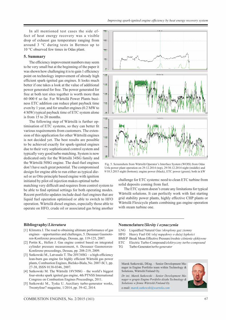
Fig. 5. Screenshots from Wärtsilä Operator’s Interface System (WOIS) from Odas Urfa power plant operation on 29.12.2014 (top), 29/30.12.2014 night (middle) and 9/10.3.2015 night (bottom); engine power (black), ETC power (green); both in kW
Bibliography/Literatura[1] Klimstra J. The road to obtaining ultimate performance of gas
engines – opportunities and challenges, 5. Dessauer Gasmoto-ren-Konferenz proceedings, Dessau, pp. 119-125, 2007.
[2] Portin K., Hellen J. Gas engine control based on integrated cylinder pressure measurement, 6. Dessauer Gasmotoren-Konferenz proceedings, Dessau, pp. 208-219, 2009.
[3] Sutkowski M., Latvasalo T. The 20V34SG – a high-efficiency lean-burn gas engine for highly efficient Wärtsilä gas power plants, Combustion Engines, Bielsko-Biala, No. 2007-SC1, pp. 27-38, ISSN 0138-0346, 2007.
[4] Sutkowski M. The Wärtsilä 18V50SG – the world’s biggest four-stroke spark ignited gas engine, 4th PTNSS International Congress on Combustion Engines Proceedings, 2011.
[5] Sutkowski M., Tyska U. Auxiliary turbo-generator works, Twentyfour7 magazine, 1/2014, pp. 39-42, 2014.
Marek Sutkowski, DEng. – Senior Development Ma-nager in Engine Portfolio team within Technology & Solutions, Wärtsilä Finland Oy.Dr inż. Marek Sutkowski – Senior Development Ma-nager w grupie Engine Portfolio działu Technology & Solutions w firmie Wärtsilä Finland Oy.e-mail: [email protected]
Nomenclature/Skróty i oznaczeniaLNG Liquidfied Natural Gas /skroplony gaz ziemnyHFO Heavy Fuel Oil /olej napędowy o dużej lepkościBMEP Break Mean Effective Pressure/średnie ciśnienie efektywneETC Electric Turbo-Compound/elektryczny turbo-compoundTG Turbo-Generator/turbo-generator