improving reproducibility whilst maintaining accuracy in
TRANSCRIPT

Improving Reproducibility whilst Maintaining Accuracy in FunctionPoint Analysis
Marcos de Freitas Jr.1, Marcelo Fantinato1, Violeta Sun1, Lucineia H. Thom2 and Vanja Garaj31School of Arts, Sciences and Humanities, University of Sao Paulo, Sao Paulo – SP, Brazil
2Institute of Informatics, Federal University of Rio Grande do Sul, Porto Alegre – RS, Brazil3Department of Electronic and Computer Engineering, Brunel University London, U.K.
Keywords: Function Point Analysis, Function Points, Business Processes, Functional Size, Functional Size Measurement.
Abstract: Existing proposals to improve the measurement reproducibility of Function Point Analysis (FPA) oversim-plify its standard rules, threatening its measurement accuracy. We introduce a new artifact called FunctionPoint Tree (FPT), which allows for full data collection required to count function points, reducing the ex-perts’ personal interpretation and thus the size variation. The new measurement method, called FPT-basedFPA (FPT-FPA), enlarges FPA standardization and systematization. Using this method allows to improvemeasurement reproducibility whilst maintaining its accuracy. Preliminary results of an empirical study showcoefficients of variation for FTP-FPA lower than the maximum expected for both reproducibility and accuracyfor some scenarios.
1 INTRODUCTION
Function Point Analysis (FPA) is a standardized siz-ing measurement method aimed at calculating a soft-ware size measure from its functional requirements,considering the functionality to be implemented onuser requests and replies (Albrecht, 1979). Resultsobtained by FPA are widely used as a reference mea-sure to derive other quantifiable parameters such aseffort, productivity or cost. The International Func-tion Point Users Group (IFPUG) is the FPA regulatoragency, responsible for the improvement and devel-opment of the rules set out in the Counting PracticesManual (CPM) (IFPUG, 2010) in version 4.3.1. FPAis also standardized by ISO/IEC 20926:2010.
However, a common criticism is FPA is rather sub-jective as it requires expert judgment, restricting itsstandardized use, as discussed in related work. Mostproposals to solve this subjectivity involve mappingrules between software modeling artifacts (such asUML) and FPA concepts to derive the functional size(de Freitas Junior et al., 2015). However, the correct-ness and completeness of existing artifact models arenot guaranteed as they were not built targeting FPA.
Although these approaches contribute at least par-tially to improving the measurement reproducibilityamong different measures, they overly simplify theCPM rules. This simplification occurs because no ar-
tifact is sufficiently detailed to fully apply the stan-dard FPA method, i.e., the IFPUG’s FPA. In the worstcases, the FPA counting rules are not applicable be-cause the artifact model lacks some piece of essentialinformation (Lavazza et al., 2008). Thus, the existingapproaches to improve reproducibility compromisethe measurement accuracy relative to the true quantityvalue. Reproducibility and accuracy are interrelatedand refer to verifying consistency and concordance ofmeasurement results obtained from repeated measure-ments, by different subjects, under similar or identicalconditions when compared to the true quantity value.
To overcome the issues mentioned above, we pro-pose a new measurement method named FunctionPoint Tree-based Function Point Analysis (FPT-FPA).We propose to add to the artifact model function re-finement tree (Insfran et al., 2002) extra informa-tion needed to count function points, arising the newmodel FPT. The extra information can be collected bya requirements analyst during the software life cycleto keep all the information needed to IFPUG’s FPAfocused in a single artifact. This enables applying allFPA rules based on the FPT, reducing individual in-terpretation because of the lack of specific informa-tion to count function points. FPT-FPA was designedto conform to IFPUG’s FPA. Thus, we aim to improvethe reproducibility of different measured quantity val-ues by reducing the variation among them, whilst en-
Freitas Jr., M., Fantinato, M., Sun, V., Thom, L. and Garaj, V.Improving Reproducibility whilst Maintaining Accuracy in Function Point Analysis.DOI: 10.5220/0007671700610072In Proceedings of the 21st International Conference on Enterprise Information Systems (ICEIS 2019), pages 61-72ISBN: 978-989-758-372-8Copyright c© 2019 by SCITEPRESS – Science and Technology Publications, Lda. All rights reserved
61
suring the accuracy of the measured quantity valuesrelative to the true quantity value, which herein refersto the value provided by IFPUG.
FPT-FPA was developed following the design sci-ence research method (Hevner et al., 2004; Wieringa,2014). Next sections present related work, the pro-posed FPT-FPA method and experiment results.
2 RELATED WORK
We identified 15 related works with proposals simi-lar to the new method proposed by us in this paper.In these works, 12 base techniques or artifacts areused, with some used more than one: UML’s classdiagram (Cantone et al., 2004; Harput et al., 2005;Abrahao et al., 2007; Rao et al., 2008; Lavazza et al.,2008; Chamundeswari and Babu, 2008; Pow-Sanget al., 2013), UML’s sequence diagram (Uemura et al.,2001; Cantone et al., 2004; Harput et al., 2005; Raoet al., 2008; Lavazza et al., 2008), UML’s use case di-agram (Cantone et al., 2004; Rao et al., 2008; Lavazzaet al., 2008), Source code (Klusener, 2003; Eda-gawa et al., 2011), Requirements engineering-basedconceptual modeling (Abrahao and Insfran, 2008),UML’s component diagram (Lavazza et al., 2008),Object-oriented hypermedia’s navigation access di-agram (Abrahao et al., 2007), Goal and scenariobased requirements text (Choi et al., 2006), Entity-relationship – data flow diagram (Lamma, 2004),Entity-relationship diagram (Fraternali et al., 2006),Vienna development method – specification language(Miyawaki et al., 2008) and Web modeling language’shypertext model (Fraternali et al., 2006).
The coverage of the standard FPA steps for these12 works ranges from about 5% (Rao et al., 2008) to70% (Lavazza et al., 2008), with an average of 30%.Our work proposes 100% coverage.
3 FPT-FPA OVERVIEW
The uniqueness of the new method is its compli-ance with all steps of IFPUG’s FPA. The new methodseeks to avoid calculating an invalid number of func-tion points when compared to the true quantity value,which might occur by simplifying the FPA’s steps.
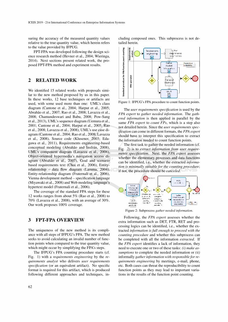
The IFPUG’s FPA counting procedure starts (cf.Fig. 1) with a requirements engineering by the re-quirements analyst who delivers user requirementsspecification (or an equivalent artifact). No specificformat is required for this artifact, which is producedfollowing different approaches and techniques, in-
cluding composed ones. This subprocess is not de-tailed herein.
Figure 1: IFPUG’s FPA procedure to count function points.
The user requirements specification is used by theFPA expert to gather needed information. The gath-ered information is then applied in parallel by thesame FPA expert to count FPs, which is a step alsonot detailed herein. Since the user requirements spec-ification can come in different formats, the FPA expertshould have to interpret this specification to extractthe information needed to count function points.
The first task to gather the needed information (cf.Fig. 2) is to extract information from user require-ments specification. Next, the FPA expert assesseswhether the elementary processes and data functionscan be identified, i.e., whether the extracted informa-tion is minimally suitable for the counting procedure;if not, the procedure should be canceled.
Figure 2: Subprocess gather needed information.
Following, the FPA expert assesses whether theextra information such as DET, FTR, RET and pro-cessing logics can be identified, i.e., whether the ex-tracted information is full enough to proceed with thecounting procedure and whether this subprocess canbe completed with all the information extracted. Ifthe FPA expert identifies a lack of information, theyneed to execute one or two of these tasks: (i) make as-sumptions to complete the needed information or (ii)informally gather information with responsible for re-quirements engineering by meetings, e-mail, phone,etc. Both cases can threat the reproducibility to countfunction points as they may lead to important varia-tions in the results of the function point counting.
ICEIS 2019 - 21st International Conference on Enterprise Information Systems
62

The FPT-FPA (Function Point Tree-based Func-tion Point Analysis) method proposes to add a newsubprocess called elaborate the FPT as an extra taskto the IFPUG’s FPA counting procedure as part of therequirements analyst duties (cf. Fig. 3). The needfor a formal FPA expert role is hence eliminated, asthe requirements analyst executes the FPA’s functionpoint counting with the support of the artifact FPT. Apart of the activities that should be performed by anFPA expert is moved to the requirements analyst andthe other part is a standard procedure that can be auto-mated. FPT-FPA improves the quality of the countingas the requirements analyst masters the software re-quirements. The requirements analyst does not needknowledge in FPA as the function point counting isautomatically executed based on the FPT available.As a potential drawback, the requirements analystneeds to be an FPT expert, but this technique is morerelated to their usual responsibilities than masteringFPA, and then knowledge on all the FPA rules andprocedures is not required.
Figure 3: Procedure for the FPT-FPA’s function point count-ing.
The FPT-FPA counting procedure also starts withthe requirements engineering, delivering the user re-quirements specification (or a corresponding artifact)by the requirements analyst. In this new context, theuser requirement specification, or at least a part, canbe firstly produced in an FPT, although not manda-tory. If the user requirements specification is prelimi-narily elaborated in the form of an FPT, it is directlyused to count FPs based on the FPT. Otherwise, therequirements analyst needs to elaborate the FPT be-fore proceeding with the counting. The details of theelaborate the FPT subprocess are presented in Sec-tion 4 whereas the details of the count FPs based onthe FPT subprocess are presented in Section 5. Be-cause of their complexities, none of these two sub-processes are presented visually).
4 FPT ELABORATION
An FPT is composed of three levels: root, intermedi-ate and leaf nodes. An illustrative example of an FPT
is shown in Fig. 4. The figure represents a HumanResources Management System (HRMS).
4.1 Level 1: Tree Root
A tree root represents the counting purpose and thecounting type. Each root must have two types of as-sociated root markers, showing: (i) the counting pur-pose, i.e., the purpose for which an organization needsto count function points according to the FPA con-cepts (cf. Fig. 5); and (ii) the counting type, referringto what will be done with the obtained measure (cf.Fig. 6). Exactly one root marker exists for the formercase and at least one root marker exists for the latter.
4.2 Level 2: Intermediate Nodes
No change was proposed for the intermediate level onthe function refinement tree as originally defined.
4.3 Level 3: Leaf Nodes
Leaf nodes represent the elementary functions of thesoftware being measured. Every leaf node must in-clude: node markers, inclusion dependency connec-tors (when applicable) and node attributes.
4.3.1 Node Markers
Node markers refer to the behavior of the elemen-tary functions during software execution. Whenever asoftware elementary function contains one or more ofthe behavior properties represented by node markers(cf. Figs. 5 and Fig. 6), these markers are added intothe corresponding leaf node. Fig. 7 shows node mark-ers whose corresponding behavior is connected to atleast one processing logic. Fig. 8 shows extra nodemarkers for the behavior of the elementary functionswith no corresponding FPA processing logic. Thenode marker PRIM represents which marker amongMAIN, BEHA and PRES is the main purpose of anelementary function. Thus, PRIM is required for aleaf node only when at least two of these three nodemarkers (MAIN, BEHA, PRES) were selected; oth-erwise, it does not apply. For example (cf. Fig. 4),the elementary function create employee contains thenode markers VALI, PRES, MESS, REFE, COND,MAIN and PRIM, so the marker PRIM was added be-cause PRES and MAIN were previously added. Thus,PRIM is to inform whether the main purpose of thiselementary function is PRES or MAIN. Specifically,in this example, the PRIM value is MAIN.
Improving Reproducibility whilst Maintaining Accuracy in Function Point Analysis
63

Figure 4: Example of FPT.
Figure 5: Root markers for counting purposes.
Figure 6: Root markers to represent for counting types.
4.3.2 Inclusion Dependency Connector betweenElementary Functions
An inclusion dependency connector shows an inclu-sion dependency relationship between two elemen-tary functions. It is used when the elementary func-tion after the arrow does not comply with the userfunctional requirements if performed alone, but onlyif the elementary function contrary to the arrow isexecuted first. For example, a user functional re-quirement might require that, after registering an em-ployee, payment details (monthly or hourly) and de-pendents have to be registered. Both following ac-tions do not comply with this user functional require-ment: (i) registering an employee without sequen-tially either registering their payment details (monthlyor hourly) or registering their dependents; and (ii) firstregistering the employee’s payment details (monthlyor hourly) or first registering the employee’s depen-dents, both without ever having previously registered
Figure 7: Node markers for the behavior of the elementaryfunctions for the FPA processing logics.
Figure 8: Extra node markers for elementary function be-havior (without corresponding FPA processing logic).
this employee. Therefore, the leaf nodes create em-ployee, create hourly paid employee, create monthlypaid employee and create dependent are connected byan inclusion dependency connector, starting from cre-ate employee first and heading toward the other three.
ICEIS 2019 - 21st International Conference on Enterprise Information Systems
64

4.3.3 Node Attributes
Node attributes show the information to be displayedto or informed by a user during execution of elemen-tary functions. For each node attribute, it should beinformed: if the information is displayed either inscreen header or footer; if the information is avail-able for data reading or input or both; and if the infor-mation has meaning stand-alone to business or onlywhen combined with another one.
4.4 Relationships Amongst Levels
All intermediate nodes are connected to the tree root(root-intermediate connections); and all leaf nodes areconnected to an intermediate node (intermediate-leafconnections). For the latter, these data accompaniesthe connections whenever appropriate: data entity la-bels; data entity markers; exclusion dependency con-nectors; and data entity attributes:
4.4.1 Data Entity Label
A data entity associated with an intermediate-leafconnection represents a software data entity main-tained or referenced by the elementary functions rep-resented by the corresponding leaf nodes. For exam-ple (cf. Fig. 4), the label position represents a dataentity maintained or referenced by four elementaryfunctions: create, update, delete and read (position).Each informed data entity (i.e., a data entity label) isaccompanied by these extra data: data entity markers;exclusion dependency connectors (whenever appro-priate); and data entity attributes – described as fol-lows. Data entities neither maintained nor referencedby elementary functions should not be modeled.
4.4.2 Data Entity Markers
Whenever a data entity presents one or more of theproperties related to the five markers showed in Fig.9, the corresponding markers are added to the corre-sponding data entity.
4.4.3 Exclusion Dependency Connector betweenData Entities
This relationship is represented by a red arrow and itattaches two data entities together. The arrow con-nects a data entity with other data entities that com-pose it so that the subsequent data entities (i.e., afterthe arrow) are parts of the first one (i.e., contrary tothe arrow). If the first data entity is deleted, all thedata entities connected to it by exclusion dependencyconnectors are also deleted as they do not exist alone.
Figure 9: Data entity markers for data entity properties.
For example (cf. Fig. 4), if a user functional require-ment requires that, by deleting an employee, all theemployee’s dependents and the employee data (what-ever they are hourly or monthly paid) are also deleted;then, the dependent data entities (dependent, hourlypaid, and monthly paid) have no meaning alone with-out a connection to an employee. Therefore, hourlypaid, monthly paid and dependent are connected viaan exclusion dependency connector to employee.
4.4.4 Data Entity Attributes
Data entity attributes represent the information storedin a data entity. The data entity attributes are main-tained or referenced by the elementary functions rep-resented by the leaf nodes. For each data entity,all data maintained or referenced needed to executethe corresponding elementary functions is informed.For each data entity attribute, it is needed to informwhether the information has meaning stand-alone tobusiness or only when combined with another one.
5 FPT-FPA-BASED COUNTING
Mapping rules are used so that the data modeled onthe FPT are used as input to FPA. The proposedrules are described herein following the IFPUG’s FPAcounting steps, i.e., according to the IFPUG’s CPMsteps.
The function point counting starts by gathering thesoftware documentation. The only input needed is theFPT and not all the relevant available artifacts as de-fined by IFPUG’s FPA. The FPT is enough and hencethe only relevant and needed artifact. Therefore, theinformation contained in this artifact supports the exe-cution of the five stages of the function point countingas follows. Only the three first stages described for IF-PUG’s FPA are detailed here as no change is proposedto the last two stages (calculating the functional sizeand documenting the counting and report the results).
Improving Reproducibility whilst Maintaining Accuracy in Function Point Analysis
65

5.1 Boundary, Scope and Purpose
The counting boundary is represented by the tree rootas it defines – as child or grandchild nodes – all thesets of functions and data entities to be addressed dur-ing the counting procedure. Any other function ordata entity not added in the tree is considered out-side of the counting border. The counting scope isrepresented by all the elementary functions (i.e., leafnodes), and all data entities of the FPT. The full setof elementary functions and data entities is consid-ered belonging to the counting scope. The countingpurpose is represented by one of these root markers:EFFO, COST, PROD or COMP. As each FPT hasonly one root marker, the marker that is added in thetree and its corresponding meaning are to define thecounting purpose. The counting type is represented inFPT-FPA by a set of one or more of these root mark-ers NEW, EVOL and EXIS. Since each FPT may haveone or more of these root markers, all the markersadded in the tree and their corresponding meaningsare to define the counting type.
5.2 Measuring Data Functions
This section presents the steps to measure data func-tions.
5.2.1 Identifying the Data Functions
Each data entity is mapped to a single data functionor as part of a composed data function, unless: (i)the data entity refers to a code data, i.e., data en-tities whose associated elementary function (i.e., aleaf node) has the node marker CONS are discarded;(ii) the data entity stores only attributes unacknowl-edged by business process users, i.e., data entitieswhose information represented by its data entity at-tributes has no meaning stand-alone to business arediscarded; (iii) the data entity describes a many-to-many relationship between two other data entity typesand contains only foreign keys, i.e., data entities hav-ing the data entity marker ASSO and presenting up totwo data entity attributes with meaning stand-alone tobusiness are discarded; and (iv) the data entity storesonly one data entity attribute, i.e., data entities pre-senting only one data entity attribute with meaningstand-alone to business are discarded.
All data entities complying with all previous con-straints are mapped to a single data function or as partof a composed data function depending on whetherthey are logically dependent or independent amongthem: (i) data entities logically independent of all theother data entities, i.e., those not linked to any otherdata entity by an exclusion dependency connector, are
directly mapped to a single data function each one.Thus, only data entities having meaning to businessby their own are mapped to single data functions; and(ii) a set of data entities logically dependent amongthem, i.e., linked one to another by exclusion depen-dency connectors, is grouped and mapped to a sin-gle data function. Thus, data entities with meaning tobusiness only when combined are mapped together toa single data function.
5.2.2 Classifying the Data Functions as InternalLogical File (ILF) or External InterfaceFile (EIF)
This classification relies on the elementary functionsthat manipulate the data entities components of thedata functions. These rules are followed to classify adata function:
• ILF: data functions that comply with this con-straint: at least one of its data entities is associatedwith an elementary function (i.e., a leaf node) thatpresents the node marker MAIN.
• EIF: data functions that comply with these con-straints: (a) none of its data entities is associatedwith any elementary function (i.e., a leaf node)that presents the node marker MAIN and (b) atleast one of its data entities presents the data en-tity marker EXTE.
5.2.3 Determining the Numbers of Data ElementType (DET) and Record Element Type(RET) for the Data Functions
For DETs, the number is counted of the data entity at-tributes (associated with its data entities) with mean-ing stand-alone to business. For RETs, it is consid-ered the data entity properties (defined by the data en-tity markers) of its data entities, based on two rules:(i) each data entity marked as SUBT, ATTR or ASSOis counted as a RET of the corresponding data func-tion; and (ii) each data entity marked as TYPE and notlinked (by exclusion dependency connector) to anydata entity marked as SUBT is counted as a RET ofthe corresponding data function.
5.2.4 Determining Complexity and Contributionfor the Data Functions
Based on the DET and RET obtained, the complex-ity (i.e., low, medium or high) of each data functionis determined, by the direct application of the val-ues pre-defined by IFPUG’s FPA. Finally, based onthese obtained complexities, the last step determinesthe contribution on the functional size of each data
ICEIS 2019 - 21st International Conference on Enterprise Information Systems
66

function, which is executed by the direct applicationof the values pre-defined for IFPUG’s FPA.
5.3 Measuring Transactional Functions
This section presents the steps to measure transac-tional functions.
5.3.1 Identifying the Elementary Processes
Each elementary function (i.e., a leaf node) added inthe FPT is mapped to a single elementary process oras part of a composed elementary process, unless: (i)the elementary function maintains or has referencesto code data, i.e., elementary functions presenting thenode marker CONS are discarded according to IF-PUG’s CPM (IFPUG, 2010); and (ii) the elementaryfunction does not process data or control informationretrieved from outside the boundary and does not senddata or control information to outside the border, i.e.,elementary functions with no node attribute inform-ing availability for user data reading or input are dis-carded.
All the elementary functions complying with pre-vious constraints are mapped to a single elementaryprocess or a part of a composed elementary processdepending on whether they are logically dependentor independent among them: (i) elementary functionslogically independent of any other elementary func-tion, i.e., those not linked to any other elementaryfunction by an inclusion dependency connector, areeach one directly mapped to a single elementary func-tion; and (ii) a set of elementary functions logicallydependent among them, i.e., linked one to anotherby inclusion dependency connectors, is grouped andmapped to a single elementary process. Accordingto this classification, an elementary process maintainssoftware in a consistent state after its execution, i.e.,it makes up a full transaction, is self-contained, and isthe smallest meaningful unit of activity.
5.3.2 Determining Unique Elementary Processes
Each unique elementary process is identified as atransactional function. Two or more elementary pro-cesses are unique elementary process if they have:(i) the same node markers representing processinglogics (i.e., VALI, CALC, CONV, FILT, COND,MAIN, REFE, DERI, BEHA, PRES and RETR); (ii)the same node attributes representing Data ElementTypes (DET) for the elementary process; and (iii) thesame data entities representing File Type Reference(FTR) for the associated elementary process.
5.3.3 Classifying the Transactional Functions asExternal Input (EI), External Output (EO)or External Inquiry (EQ)
This classification relies on the primary intention (i.e.,the node marker PRIM) of the elementary functionsthat compose the transactional functions. These rulesare followed to classify a transaction function:
• EI: transactional functions that comply with thisconstraint – at least one of its elementary func-tions presents the node marker PRIM showing asthe primary intention the node markers MAIN orBEHA.
• EO: transactional functions that comply withthese constraints – (a) none of its elementaryfunctions presents the node marker PRIM show-ing as the primary intention the node markersMAIN or BEHA, (b) at least one of its elemen-tary functions presents the node markers CALC,MAIN, BEHA or DERI and (c) at least one of itselementary functions marked as CALC, MAIN,BEHA or DERI presents at least one node at-tribute informing availability for user data read-ing.
• EQ: transactional functions that comply withthese constraints – (a) none of its elementaryfunctions presents the node marker PRIM show-ing as the primary intention the node markersMAIN or BEHA, (b) none of its elementary func-tions presents the node markers CALC, MAIN,BEHA and DERI and (c) at least one of its ele-mentary functions presents one or more node at-tributes informing availability for user data read-ing.
5.3.4 Determining the Numbers of DET andFTR for the Transactional Functions
To determine the number of DETs for a transactionalfunction, the number is counted of node attributes (as-sociated with its elementary functions) with meaningstand-alone to business. These extra rules are: (i) ifthe information corresponding to a node attribute isdisplayed only in the screen’s header or footer, thenthis node attribute is discarded for the counting ofDETs; (ii) if one of the elementary functions presentsthe node marker MESS, it is counted an extra DETfor the corresponding transactional function, consid-ering the functional ability to display a message to theuser; and (iii) if one of the elementary functions doesnot show the node marker BATC, it is counted one ex-tra DET for the corresponding transactional function,taking the functional ability to initiate some action.
Improving Reproducibility whilst Maintaining Accuracy in Function Point Analysis
67

Then, to determine the number of FTRs for atransactional function, the data entities related to theelementary functions constituents of this transactionfunction is considered. Each data entity identified as adata function (or as part of a data function) and asso-ciated with the corresponding transactional functionis counted as an FTR for this transactional function.
5.3.5 Determining Complexity and Contributionfor the Transactional Functions
Based on the numbers of DET and FTR obtained, thecomplexity (i.e., low, medium or high) of each trans-actional function is determined, by the direct applica-tion of the values pre-defined for IFPUG’s FPA. Fi-nally, based on these obtained complexities, the laststep determines the contribution on the functional sizeof each transactional function, which is executed bythe direct application of the values pre-defined for IF-PUG’s FPA.
6 EVALUATION OF FPT-FPA
An empirical study was conducted to evaluate FPT-FPA regarding its measurement reproducibility andaccuracy. A quasi-experiment was run to test thehypothesis that FPT-FPA enables a higher repro-ducibility and accuracy than IFPUG’s FPA. A quasi-experiment was applied since it would be impracticalto randomly select the subjects because of the com-plexity of this study (Easterbrook et al., 2008; Kamp-enesa et al., 2009).
6.1 Support Tool
A tool was prototyped to support the function pointcounting based on the FPT-FPA method. The proto-type was aimed at demonstrating the automation fea-sibility of FPT-FPA and helping verify and validatethe proposed method as a proof of concept. The eval-uation also considered the method execution manu-ally to ensure its correctness regardless of whether thetool is used or whether the tool is correctly imple-mented. A full tool for commercial purposes was notthe primary goal and hence non-functional require-ments such as usability, performance and others werenot addressed. The FPT was simplified on the graphicrepresentation of the elements root markers, nodesand data entity labels (cf. Fig. 4).
The prototype tool was developed on the .NET4.5 framework, using the programming language C#according to the object-oriented paradigm. For datastorage, XML format was used with a set of properties
called LINQ (Language Integrated Query), which en-ables the development of queries using the C# syntax.The prototype tool architecture is organized based onthe MVC (Model View Controller) software architec-tural pattern [38]. In addition to the three standardMVC layers, an extra layer – called persistence – wascreated, dedicated specifically to the communicationbetween software and database, to maximize the ben-efits of the logical separation provided by the MVClayers.
Fig. 10 shows a use case diagram representingthe prototype functional requirements. The diagrambrings five main use cases to be used by the only ac-tor to whom the system is designed – the requirementsanalyst. Thus, with the proposed method, an FPA ex-pert would be no longer needed and the requirementanalyst would receive some extra tasks.
Fig. 11 shows a screenshot of the prototype. Thefigure shows a part of the FPT previously shown inFig. 4, with limitations of the prototype because of thescenario mentioned at the beginning of this section.The full FPT is not shown in this figure because ofreadability.
6.2 Experiment Design
This section presents the planning of the experimentthat was carried out. The experiment was designedbased on a framework for experimental software engi-neering (Wohlin et al., 2012). The experiment aimedto investigate whether the proposed method showsbetter reproducibility and accuracy levels when com-pared to reference values obtained by IFPUG’s FPA.Based on the GQM (Goal/Question/Metric) template(Basili and Rombach, 1998), the goal pursued in thisexperiment was: to analyze the proposed method forthe purpose of evaluating it in comparison with IF-PUG’s FPA regarding reproducibility and accuracy,from the point of view of the researcher, in the contextof M.Sc. students and practitioners measuring func-tion points.
The analysis of the results considered:
• Reproducibility as the agreement between themeasurement results of different subjects. Repro-ducibility was examined as calculated by differentsubjects by FPT-FPA, by comparing the obtainedcalculation results among subjects. We expectedto get a coefficient of variation for the results withFPT-FPA lower than 17.67%, as this is the aver-age of the coefficients of variation found in re-lated work on reproducibility (Connolley, 1990;Low and Jeffery, 1990; Kemerer, 1993). Althoughthe only found sources are out-of-date, they canbe used as a reference value as FPA can be kept
ICEIS 2019 - 21st International Conference on Enterprise Information Systems
68

Figure 10: Use case diagram for the support prototype.
Figure 11: Screenshot of the developed prototype.
without substantial changes along these years.
• Accuracy as the agreement between the measure-ment results and the true quantity value. Accuracywas examined as calculated by different subjectsby FPT-FPA, by comparing the results with theofficial reference value as reported by IFPUG. Weexpected to get a coefficient of variation betweenthe results with FPT-FPA and the IFPUG’s officialvalue lower than 10.71% as this is the average ofthe coefficients of variation found in related workon accuracy (Uemura et al., 2001; Lamma, 2004;Fraternali et al., 2006; Miyawaki et al., 2008;Abrahao and Insfran, 2008; Adem and Kasirun,2010; Edagawa et al., 2011).
For the analysis of these two criteria, the totalnumbers of measured function points were consid-ered, i.e., the sum of all Base Functional Compo-nents (BFC), from both data functions (ILF and EIF)and transactional functions (EI, EO and EQ). Thus,the reproducibility and accuracy analyses were per-
formed by evaluating the method as a whole and notfocusing on specific components. Regardless, somebreakdown values are also presented relating to BFCsto help identify where reproducibility and accuracyproblems may be located specifically.
The other parameters of the designed experimentare presented as follows:
• Subjects: a group of 17 participants with an ed-ucation background in information systems (orsimilar) was selected. Most of the subjects had theexperience of working in the industry for between1 and 20 years. The subjects were selected byconvenience, with the majority being from orga-nizations related to software and systems develop-ment. The remaining subjects were selected froman academic stricto sensu graduate program. Asthe proposal assumes that the FPA expert wouldbe no longer needed, as the elaboration of theFPT can be done directly by other roles, the se-lected subjects were mainly requirements or sys-
Improving Reproducibility whilst Maintaining Accuracy in Function Point Analysis
69

tems analysts (or related roles), who are the tar-get users of the proposed method. The only con-straint was that they should not have previouslyknown FPA to avoid the application of the previ-ous experience and personal techniques in manag-ing the provided information instead of using theFPT-FPA method.
• Variables:– Independent Variables: the primary indepen-
dent variable refers to the methods being com-pared – FTP-FPA and FPA. The secondary in-dependent variable was the type of executionof the FTP-FPA method, i.e., manual or auto-mated.
– Dependent Variables: the two dependentsvariables are – reproducibility and accuracy.
• Treatment: the higher-level treatment refers tothe primary independent variable – FPT-FPA ver-sus IFPUG’s FPA. All the subjects carried outonly the FPT-FPA method, contributing to an ob-servation from each subject. The IFPUG’s FPAmethod was not carried out during the experimentexecution as the values for reproducibility and ac-curacy found in the literature were used as a refer-ence for comparison with FPT-FPA. As the lower-level treatment, to address the secondary goal, thesubjects were randomly assigned to two groups tocompare the performance for: manual execution– eight subjects executed FPT-FPA manually; andautomated execution – nine subjects executedPPT-FPA supported by the prototype.
• Instrumentation:– Training: the subjects were provided with
the description of the proposed method, anoverview of the experiment and no example.
– Object: a software specification previouslymeasured by IFPUG’s was used with 125 func-tion points (IFPUG, 2010); all the subjectselaborated an FPT for the object; subsequently,they counted the function points for this sys-tem, based on the elaborated tree.
– Prototype or Results Form: the prototype wasprovided to those subjects who should use itduring the experiment and a form was providedto the other ones.
– Characterization Form: each subject reportedbasic personal information and the total timespent.
• Hypotheses:– Hypothesis A: refers to the primary indepen-
dent variable and the dependent variable of re-producibility: the hypothesis is that FPT-FPA
has a reproducibility coefficient of variationequal to or greater than 17.67%, i.e., FPT-FPAhas an equivalent or higher reproducibility thanIFPUG’s FPA.
– Hypothesis B: refers to the primary indepen-dent variable and the dependent variable of ac-curacy: the hypothesis is that FPT-FPA hasan accuracy coefficient of variation equal orgreater than 10.71%, i.e., FPT-FPA has anequivalent or higher accuracy than IFPUG’sFPA.
6.3 Subjects Profile
Fig. 12 shows the profile of the subjects, includ-ing their education background, current position andwork experience. All the 17 subjects held at least agraduate degree in information systems or related ar-eas and seven of them also held a lato sensu post-graduate degree. From them, 13 were working in theindustry, with the majority acting as a system or re-quirements analyst, and also one developer and onemanager. Some of these 13 subjects working in the in-dustry were also enrolled in a Master of Science Grad-uate Program in Information Systems. The remainingfour subjects to complete 17 were fully enrolled in thesame master program; with some previous experiencein the industry. The length of work experience for thesample ranges from 1 to 20 years.
6.4 Results Achieved
Table 1 shows a results breakdown per subject. Theseresults include the number of function points mea-sured, the time spent and the type of execution – Man-ual (M) or Automated (A). Table 2 shows the meanvalues for the function points measured by FPT-FPAand other derived values needed to evaluate repro-ducibility and accuracy, for both automated and man-ual executions.
As for time spent by the subjects applying FPT-FPA, the following mean values were obtained (inhours): 2.45 for execution via support prototype and4.48 for manual execution. The relationship betweenthe two groups was 55% automated/manual.
For reproducibility, the coefficient of variation,relative to the mean (to measure reproducibility), cal-culated as 9.99%, when observing the measurementresults for all subjects is nearly half the maximum de-fined as the study goal compared to the related work(i.e., 17.67%). This value shows that, on reproducibil-ity, the proposed method is on average substantiallybetter than other approaches present in literature.
ICEIS 2019 - 21st International Conference on Enterprise Information Systems
70

Figure 12: Selected subjects profile.
Table 1: Measurement results – totalized data and transactional functions (Reference value = IFPUG’s official value).
Ref. value P1 P2 P3 P4 P5 P6 P7 P8 P9 P10 P11 P12 P13 P14 P15 P16 P17 Mean# of FPs (total) 125 104 109 88 110 111 102 101 124 124 122 124 118 124 128 128 122 130 115.82Execut. time (h) N/A 1.7 2.5 2.6 1.1 2.3 2.1 4.5 2.8 3.5 4.2 3.8 3.2 3.0 5.0 8.0 7.5 2.1 3.52Execut. type N/A A A A A A A A A M M M M M M M M M –
Table 2: Consolidated results on reproducibility and accuracy (totalized data and transactional functions).
Relative to the mean Relative to the true quantity value –(reproducibility) IFPUG’s official value (Accuracy)
Perspective of analysis Mean of themeasured values
Standarddeviation
Coefficientof variation
Standarddeviation
Coefficientof variation
All subjects (M+A) 115.82 11.57 9.99% 14.76 11.81%Only manually (M) 124.44 3.50 2.81% 3.54 2.83%Only automated (A) 106.13 9.64 9.08% 21.19 16.95%
For accuracy, the coefficient of variation relativeto the IFPUG’s official value, calculated as 11.81%based on the measurement results for all subjects, isslightly higher than the maximum defined as the studygoal compared to the related work (i.e., 10.71%). Thisvalue shows that, on accuracy, the proposed method isless accurate than those found in related work. How-ever, when considering different perspectives, betterresults are also found. For example, when the re-sults are evaluated taking into account only the sub-jects who executed the method manually, it is alsoobserved a better coefficient of variation calculated as2.83%, which is much lower than the maximum valuedefined as the study goal (i.e., 10.71%).
7 CONCLUSION
FPA has played a key role in private and publicorganizations. It is imperative to get reliable andvalid results with the application of this measure-ment method. However, several issues exist regard-ing the reproducibility and accuracy of the functionpoint counting executed using IFPUG’s FPA. Thiswork aimed to define a measurement method calledFunction Point Tree-based Function Point Analysis(FPT-FPA), aiming to provide a better standardiza-tion to count function points. This standardization isachieved by a new artifact model that includes all in-
formation needed for the counting, called FPT. TheFPT enables counting with improved reproducibilityamong different measures whilst maintaining the ac-curacy with IFPUG’s FPA.
The evaluation showed that the proposed methodpresented positive values when the proposed methodwas manually executed, on both reproducibility andaccuracy; showing that the proposed method has con-ceptual soundness. However, the results were not sogood when the proposed method was executed sup-ported by the prototype, mainly on accuracy; show-ing that the prototype solution still requires adjusts topresent a more important contribution.
Future works may include finding the better ad-justments to the method conceptual rules and the pro-totype to ensure that all the functional requirementsare completely and correctly added by the technicalusers in the FPT. These actions are needed to deliverresults with a higher reproducibility and accuracy, re-gardless of external factors.
REFERENCES
Abrahao, S. and Insfran, E. (2008). A metamodeling ap-proach to estimate software size from requirementsspecifications. In Proceedings of the 34th EuromicroConference Software Engineering and Advanced Ap-plications, pages 465–475.
Improving Reproducibility whilst Maintaining Accuracy in Function Point Analysis
71

Abrahao, S., Mendes, E., Gomez, J., and Insfran, E. (2007).A model-driven measurement procedure for sizingweb applications: Design, automation and validation.In Proceedings of the 10th International Conferenceon Model Driven Engineering Languages and Sytems,pages 467–481.
Adem, N. A. Z. and Kasirun, Z. M. (2010). Automatingfunction points analysis based on functional and nonfunctional requirements text. In Proceedings of the2nd International Conference on Computer and Au-tomation Engineering, pages 664–669.
Albrecht, A. J. (1979). Measuring application develop-ment productivity. In Proceedings of the Joint SHARE,GUIDE, and IBM Application Development Sympo-sium, pages 83–92.
Basili, V. R. and Rombach, H. D. (1998). The TAMEproject: towards improvement-oriented software envi-ronments. IEEE Transactions on Software Engineer-ing, 14(6):758–773.
Cantone, G., Pace, D., and Calavaro, G. (2004). Applyingfunction point to unified modeling language: Conver-sion model and pilot study. In Proceedings of the 10thInternational Symposium on Software Metrics, pages280–291.
Chamundeswari, A. and Babu, C. (2008). An extendedfunction point approach for size estimation of object-oriented software. pages 139–145.
Choi, S., Park, S., and Sugumaran, V. (2006). Functionpoint extraction method from goal and scenario basedrequirements text. In Proceedings of the 11th Inter-national Conference on Applications of Natural Lan-guage to Information Sytems, pages 12–24.
Connolley, M. J. (1990). An Empirical Study of FunctionPoint Analysis Reliability. MIT, USA.
de Freitas Junior, M., Fantinato, M., and Sun, V. (2015).Improvements to the function point analysis method:A systematic literature review. IEEE Transactions onEngineering Management, 62(4):495–506.
Easterbrook, S., Singer, J., Storey, M.-A., and Damian, D.(2008). Selecting empirical methods for software En-gineeringeering research, pages 285–311.
Edagawa, T., Akaike, T., Higo, Y., Kusumoto, S., Hanabusa,S., and Shibamoto, T. (2011). Function point mea-surement from web application source code based onscreen transitions and database accesses. Journal ofSytems and Software, 84(6):976–984.
Fraternali, P., Tisi, M., and Bongio, A. (2006). Automat-ing function point analysis with model driven devel-opment. In Proceedings of the 16th Conference ofthe Center for Advanced Studies on Collaborative Re-search, page 18.
Harput, V., Kaindl, H., and Kramer, S. (2005). Extend-ing function point analysis of object-oriented require-ments specifications. In Proceedings of the 11th Inter-national Software Metrics Symposium, pages 39–39.
Hevner, A. R., March, S. T., Park, J., and Ram, S. (2004).Design science in information system research. MISQuarterly, 28(1):75–105.
IFPUG (2010). Function Point Counting Practices Man-
ual, release 4.3.1. International Function Point UsersGroup, Westerville, Ohio.
Insfran, E., Pastor, O., and Wieringa, R. (2002). Require-ments engineeringeering-based conceptual modelling.Requirements Engineering, 7(2):61–72.
Kampenesa, V. B., Dybaa, T., Hannaya, J. E., and Sjøberga,D. I. K. (2009). A systematic review of quasi-experiments in software engineeringeering. Informa-tion and Software Technology, 51(1):71–82.
Kemerer, C. F. (1993). Reliability of function points mea-surement: A field experiment. Communications of theACM, 36(2):85–97.
Klusener, S. (2003). Source code based function point anal-ysis for enhancement projects. In Proceedings of the29th International Conference on Software Mainte-nance, pages 373–376.
Lamma, E. (2004). A system for measuring function pointsfrom an ER-DFD specification. The Computer Jour-nal, 47(3):358–372.
Lavazza, L. A., del Bianco, V., and Garavaglia, C. (2008).Model-based functional size measurement. In Pro-ceedings of the 2nd International Symposium onEmpirical Software Engineering and Measurement,pages 100–109.
Low, G. C. and Jeffery, D. R. (1990). Function pointsin the estimation and evaluation of the software pro-cess. IEEE Transactions on Software Engineering,16(1):64–71.
Miyawaki, T., Iijima, J., and Ho, S. (2008). Measuring func-tion points from VDM-SL specifications. In Proceed-ings of the 5th International Conference on ServiceSytems and Service Manag., pages 1–6.
Pow-Sang, J. A., Villanueva, D., Flores, L., and Rusu, C.(2013). A conversion model and a tool to identifyfunction point logic files using UML analysis class di-agrams. In Proceedings of the Joint Conference of the23rd International Workshop on Software Measure-ment and the 8th International Conference on Soft-ware Process and Product Measurement, pages 126–134.
Rao, K. K., Nagaraj, S., Ahuja, J., Apparao, G., Kumar,J. R., and Raju, G. S. V. P. (2008). Measuring the func-tion points from the points of relationships of UML.In Proceedings of the 1st International Conferenceon Computer and Electrical Engineering, pages 748–752.
Uemura, T., Kusumoto, S., and Inoue, K. (2001). Function-point analysis using design specifications based on theUnified Modelling Language. Journal of SoftwareMaintenance: Research and Practice, 13(4):223–243.
Wieringa, R. J. (2014). Design science methodology forinformation systems and software Engineeringeering.Springer.
Wohlin, C., Runeson, P., Host, M., Ohlsson, M. C., Reg-nell, B., and Wesslen, A. (2012). Experimentation inSoftware Engineeringeering. Springer, 1 edition.
ICEIS 2019 - 21st International Conference on Enterprise Information Systems
72