improving product design with ips-dfx …druge strane, modul za upravljanje tokovima kompleksnih...
TRANSCRIPT

Z. Anišić et al. Unapređenje konstrukcije proizvoda s IPS-DFX metodologijom ugrađenom u PLM softver
Tehnički vjesnik 20, 1(2013), 183-193 183
ISSN 1330-3651 (Print), ISSN 1848-6339 (Online) UDC/UDK 658.512.018.2:004.738.5
IMPROVING PRODUCT DESIGN WITH IPS-DFX METHODOLOGY INCORPORATED IN PLM SOFTWARE Zoran Anišić, Ivica Veža, Nikola Suzić, Nemanja Sremčev, Anja Orčik
Subject review The paper presents improvement of a product through the application of Design for Excellence (DFX) tools for assembly, manufacturing and environmental protection that are incorporated into the commercial software Siemens Teamcenter for Product Lifecycle Management (PLM). Complex database, that is a heart of every PLM software, allows easy access to all necessary data for DFX analyses starting from functional requirements, geometric CAD models, technology and process data related to the production system, and can be also used as a Knowledge Database (KDB) for collecting company’s experience. On the other hand, a module for management of complex processes flows, such as proposals for design changes, evaluation, verification and modification of a new revision of the product, allows easy parallel work of all participants in the process with minimum drawbacks. Successful implementation of the research is done on the model of the mechanical bathroom scale, through the required number of iterations. Keywords: Design for Excellence – DFX, Product Lifecycle Management – PLM, Siemens Teamcenter PLM software
Unapređenje konstrukcije proizvoda s IPS-DFX metodologijom ugrađenom u PLM softver
Pregledni članak Rad predstavlja unapređenje proizvoda kroz aplikaciju alata za konstruiranje za izvrsnost (DFX) za montažu, proizvodnju i zaštitu životne sredine koji su ugrađeni u komercijalni softver Siemens Teamcenter za menadžment životnog ciklusa proizvoda (PLM). Kompleksna baza podataka, koja je srce svakog PLM softvera, dopušta lak pristup svim potrebnim podacima DFX analiza, od funkcionalnih zahtjeva, geometrijskih CAD modela, do podataka o tehnologiji i procesima vezanim za proizvodni sustav, a može se također uporabiti kao baza znanja (KDB) za objedinjavanje iskustava jedne kompanije. S druge strane, modul za upravljanje tokovima kompleksnih procesa, kao što su prijedlozi za izmjene u konstruiranju, evaluacija, verifikacija i modifikacija nove verzije proizvoda, dopušta olakšan paralelni rad svih učesnika u procesu s minimalnim preprekama. Uspješna implementacija istraživanja provedena je na modelu mehaničke vage za kupaonicu, kroz potreban broj iteracija. Ključne riječi: konstruiranje za izvrsnost – DFX, menadžment životnog ciklusa proizvoda – PLM, Siemens Teamcenter PLM softver
1 Introduction
Shortening of product lifecycles and increase of product varieties [1, 2] are one of the main characteristics of today’s market development. In the up growing race for faster product release and indulging the needs and wishes of customer centric market, design of products has become one of the most important steps in the product development. Impacting all the late phases of product lifecycle, design has direct influence on cost of the product and the production, ecology, ability for assembling or disassembling of the product and other for product lifecycle relevant issues [3].
Figure 1 Requirements to the new product set by
different stakeholders [5]
Moreover, the concept development phase is one of
the main knowledge intensive phases of the product lifecycle management [4]. In that frame a set of design tools is being applied by design engineers for obtaining
the desired characteristics of the product in all stages of product lifecycle, Fig. 1.
Design for Excellence (DFX) is an umbrella term used to denote design philosophies and methodologies which aim to improve designs by raising the designer’s awareness for a certain product lifecycle value or characteristic represented by X [6]. It covers a wide range of specific design guidelines. Each of them addresses a particular issue that is caused by, or affects the characteristics of a product [7]. In Fig. 2 development of DFX can be seen and will be described shortly below.
Figure 2 The sequence of the development of the DFX [8]
Design for Assembly (DFA) is one of the most
important members of DFX family. The application of DFA results in product more suitable for assembly. The application of DFA could also result in more complex parts with additional features [9]. There is also a DFA for automated assembly. This type of DFA will for example enable the supplying of parts in right orientation for
Improving product design with IPS-DFX methodology incorporated in PLM software Z. Anišić et al.
184 Technical Gazette 20, 1(2013), 183-193
assembly process. Nowadays DFA is addressed in the frame of DFA/DFD where DFD is Design for Disassembly.
Design for Manufacture (DFM) [10] includes a wide range of design rules and guidelines defined from the perspective of improving the manufacturability of parts. Applying DFM will impact directly on end process capability. DFM is with DFA a predecessor of all DFX tools.
Design for Environment (DFE) has a purpose to reduce the potential risk a product could have to people and the environment by finding ways to prevent pollution. Design for Disassembly (DFD) and Design for Recycling (DFR) are a part of DFE tool.
Other DFX’s that are most used are Design for Quality (DFQ), Design for Cost (DFC), Design for User Fulfilment (DFUF), Design for Mass Production (DFMASS), Design for Packaging (DFP), Design for Reliability and Maintenance (DFRM) and Design for Rapid-prototyping (DFR/VP).
Recently, new product development (NPD) has been widely performed in networked environment [11]. There is a huge advantage in cooperation among companies, for example, shortening of the product development process, using common resources, knowledge or technology, and cost and risk sharing [12]. Connecting the participants in the process of product development in internet surroundings enables the companies to reduce costs and to shorten the time necessary for developing new, or improving present products [13]. An adequate way of communication and decision making strategy is needed among all of the involved participants, for the reduction of product development time, cost, and diminishing error occurrence.
The development of sophisticated software tools in the field of Product Lifecycle Management (PLM) has opened a possibility for efficient product development and successful cooperation between engineers, not only having in mind the concurrent engineering, but also a collaboration between the different functions of the company [14]. Managing of the projects in PLM software has taken development of products on a whole new level [15].
PLM is the process of managing the whole lifecycle of a product starting from generating an idea, concept description, business analyses, product design and solution architecture and technical implementation, to the successful entrance to the market, service, maintenance and product improvement [16, 17, 18]. The goal is to enable product development teams and manufacturing teams to work together in the product lifecycle as early as possible to minimize production costs, improve product quality, deliver more reliable products [19].
The primary goal of the research shown in the paper is the improvement of a product design in a conceptual phase, through built-in DFX methodology in PLM environment, supported with the Siemens Teamcenter software. The results of the application DFA, DFM and DFE tools will be shown through series of iterations, managed in PLM software, significantly saving time and money. 2 IPS-DFX methodology
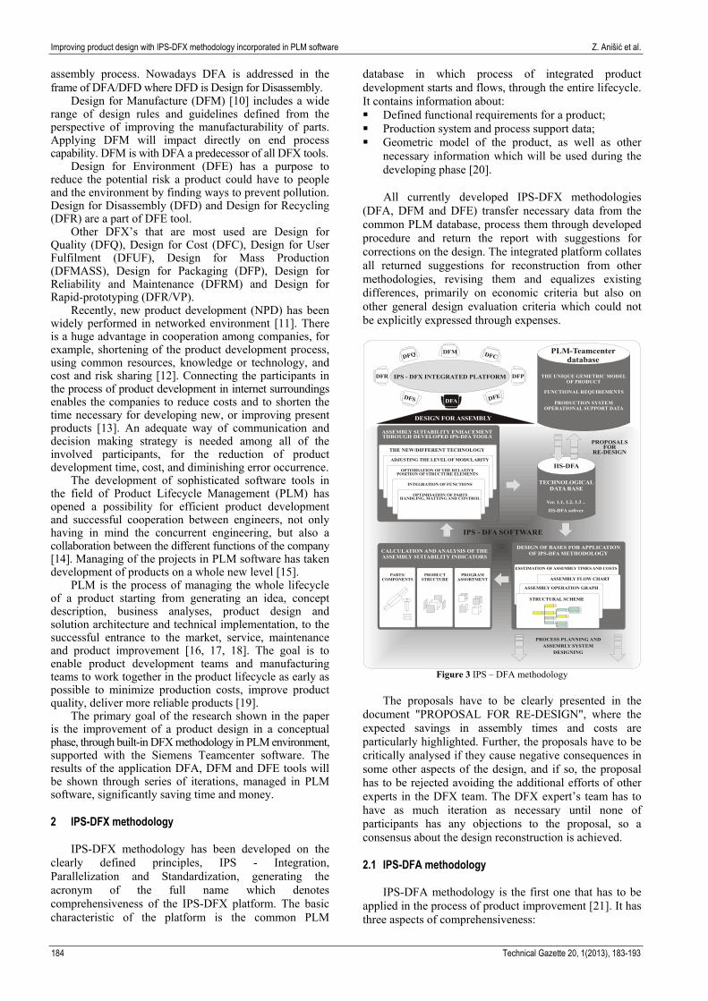
IPS-DFX methodology has been developed on the clearly defined principles, IPS - Integration, Parallelization and Standardization, generating the acronym of the full name which denotes comprehensiveness of the IPS-DFX platform. The basic characteristic of the platform is the common PLM
database in which process of integrated product development starts and flows, through the entire lifecycle. It contains information about: Defined functional requirements for a product; Production system and process support data; Geometric model of the product, as well as other
necessary information which will be used during the developing phase [20]. All currently developed IPS-DFX methodologies
(DFA, DFM and DFE) transfer necessary data from the common PLM database, process them through developed procedure and return the report with suggestions for corrections on the design. The integrated platform collates all returned suggestions for reconstruction from other methodologies, revising them and equalizes existing differences, primarily on economic criteria but also on other general design evaluation criteria which could not be explicitly expressed through expenses.
STRUCTURAL SCHEME
ASSEMBLY OPERATION GRAPH
ASSEMBLY FLOW CHART
ESSTIMATION OF ASSEMBLY TIMES AND COSTS
DESIGN OF BASES FOR APPLICATIONOF IPS-DFA METHODOLOGY
PARTS/COMPONENTS
CALCULATION AND ANALYSIS OF THEASSEMBLY SUITABILITY INDICATORS
OPTIMISATION OF PARTSHANDLING, MATTING AND CONTROL
INTEGRATION OF FUNCTIONS
OPTIMISATION OF THE RELATIVEPOSITION OF STRUCTURE ELEMENTS
ADJUSTING THE LEVEL OF MODULARITY
THE NEW/DIFFERENT TECHNOLOGY
ASSEMBLY SUITABILITY ENHACEMENTTHROUGH DEVELOPED IPS-DFA TOOLS
PROCESS PLANNING ANDASSEMBLY SYSTEM
DESIGNING
IPS - DFX INTEGRATED PLATFORM
DFA
DFMDFQ DFC
DFE
DFP
DFS
DFR
PRODUCTSTRUCTURE
PROGRAMASSORTMENT
PLM-Teamcenterdatabase
THE UNIQUE GEMETRIC MODEL OF PRODUCT
FUNCTIONAL REQUIREMENTS
PRODUCTION SYSTEM OPERATIONAL SUPPORT DATA
DESIGN FOR ASSEMBLY
PROPOSALSFOR
RE-DESIGN
IIS-DFA
Ver. 1.1, 1.2, 1.3 ..
IIS-DFA softver
IPS - DFA SOFTWARE
TECHNOLOGICALDATA BASE
Figure 3 IPS – DFA methodology
The proposals have to be clearly presented in the
document "PROPOSAL FOR RE-DESIGN", where the expected savings in assembly times and costs are particularly highlighted. Further, the proposals have to be critically analysed if they cause negative consequences in some other aspects of the design, and if so, the proposal has to be rejected avoiding the additional efforts of other experts in the DFX team. The DFX expert’s team has to have as much iteration as necessary until none of participants has any objections to the proposal, so a consensus about the design reconstruction is achieved. 2.1 IPS-DFA methodology
IPS-DFA methodology is the first one that has to be applied in the process of product improvement [21]. It has three aspects of comprehensiveness:
Z. Anišić et al. Unapređenje konstrukcije proizvoda s IPS-DFX metodologijom ugrađenom u PLM softver
Tehnički vjesnik 20, 1(2013), 183-193 185
Analysis at the level of the product assortment, structure of the basic product and at the component part level;
Design rating with ability of detecting drawbacks and the developed tools for design improvement as generators of ideas and suggestions;
Integration into the procedure of assembly process planning and system designing. Fig. 3 illustrates the concept of comprehensive IPS-DFA
methodology based on the principles within the frame of IPS-DFA platform, enabling simultaneous application of all available IPS-DFX methodologies.
In the first phase of the product analysis, there is a set of 11 different assembly suitability indicators that have to be determined, where assembly time and costs are dominant. In the second phase, methodology assumes application of the five levels of different DFA tools, starting from: part optimization level, reducing part’s number through integration of functions, optimization of the relative position of the product structure, adjusting the level of modularity and conceptual level, which consider the possible use of different technology. The results are suggestions and/or solutions for design improvement. If DFA expert is not satisfied with the new version of the product, process is repeated through the necessary number of iteration, before sending it to confirmation.
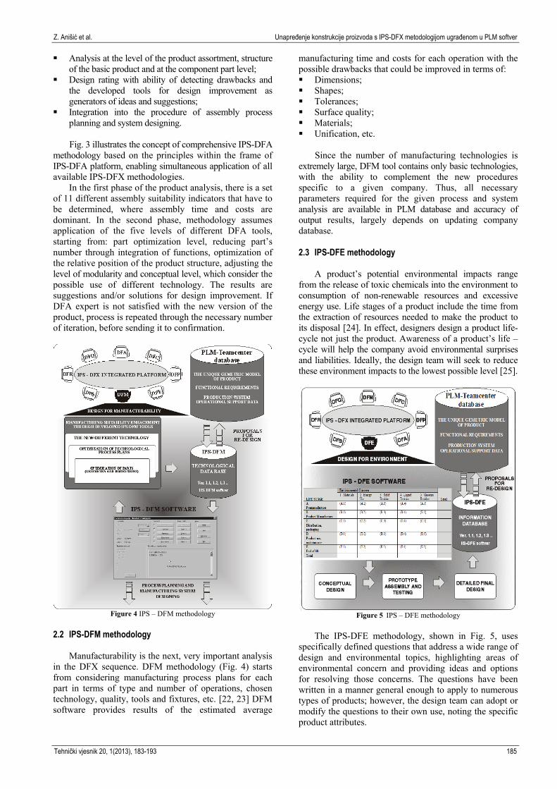
Figure 4 IPS – DFM methodology
2.2 IPS-DFM methodology
Manufacturability is the next, very important analysis
in the DFX sequence. DFM methodology (Fig. 4) starts from considering manufacturing process plans for each part in terms of type and number of operations, chosen technology, quality, tools and fixtures, etc. [22, 23] DFM software provides results of the estimated average
manufacturing time and costs for each operation with the possible drawbacks that could be improved in terms of: Dimensions; Shapes; Tolerances; Surface quality; Materials; Unification, etc.
Since the number of manufacturing technologies is
extremely large, DFM tool contains only basic technologies, with the ability to complement the new procedures specific to a given company. Thus, all necessary parameters required for the given process and system analysis are available in PLM database and accuracy of output results, largely depends on updating company database. 2.3 IPS-DFE methodology
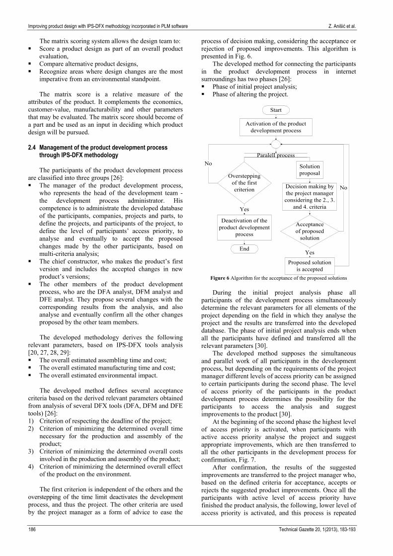
A product’s potential environmental impacts range from the release of toxic chemicals into the environment to consumption of non-renewable resources and excessive energy use. Life stages of a product include the time from the extraction of resources needed to make the product to its disposal [24]. In effect, designers design a product life-cycle not just the product. Awareness of a product’s life – cycle will help the company avoid environmental surprises and liabilities. Ideally, the design team will seek to reduce these environment impacts to the lowest possible level [25].
Figure 5 IPS – DFE methodology
The IPS-DFE methodology, shown in Fig. 5, uses
specifically defined questions that address a wide range of design and environmental topics, highlighting areas of environmental concern and providing ideas and options for resolving those concerns. The questions have been written in a manner general enough to apply to numerous types of products; however, the design team can adopt or modify the questions to their own use, noting the specific product attributes.
Improving product design with IPS-DFX methodology incorporated in PLM software Z. Anišić et al.
186 Technical Gazette 20, 1(2013), 183-193
The matrix scoring system allows the design team to: Score a product design as part of an overall product
evaluation, Compare alternative product designs, Recognize areas where design changes are the most
imperative from an environmental standpoint. The matrix score is a relative measure of the
attributes of the product. It complements the economics, customer-value, manufacturability and other parameters that may be evaluated. The matrix score should become of a part and be used as an input in deciding which product design will be pursued.
2.4 Management of the product development process
through IPS-DFX methodology The participants of the product development process
are classified into three groups [26]: The manager of the product development process,
who represents the head of the development team - the development process administrator. His competence is to administrate the developed database of the participants, companies, projects and parts, to define the projects, and participants of the project, to define the level of participants’ access priority, to analyse and eventually to accept the proposed changes made by the other participants, based on multi-criteria analysis;
The chief constructor, who makes the product’s first version and includes the accepted changes in new product’s versions;
The other members of the product development process, who are the DFA analyst, DFM analyst and DFE analyst. They propose several changes with the corresponding results from the analysis, and also analyse and eventually confirm all the other changes proposed by the other team members. The developed methodology derives the following
relevant parameters, based on IPS-DFX tools analysis [20, 27, 28, 29]: The overall estimated assembling time and cost; The overall estimated manufacturing time and cost; The overall estimated environmental impact.
The developed method defines several acceptance
criteria based on the derived relevant parameters obtained from analysis of several DFX tools (DFA, DFM and DFE tools) [26]: 1) Criterion of respecting the deadline of the project; 2) Criterion of minimizing the determined overall time
necessary for the production and assembly of the product;
3) Criterion of minimizing the determined overall costs involved in the production and assembly of the product;
4) Criterion of minimizing the determined overall effect of the product on the environment. The first criterion is independent of the others and the
overstepping of the time limit deactivates the development process, and thus the project. The other criteria are used by the project manager as a form of advice to ease the
process of decision making, considering the acceptance or rejection of proposed improvements. This algorithm is presented in Fig. 6.
The developed method for connecting the participants in the product development process in internet surroundings has two phases [26]: Phase of initial project analysis; Phase of altering the project.
Start
Activation of the productdevelopment process
Oversteppingof the firstcriterion
Paralell process
Solutionproposal
Acceptanceof proposed
solution
Proposed solutionis accepted
Yes
No
No
Deactivation of theproduct development
process
End
Yes
Decision making bythe project managerconsidering the 2., 3.
and 4. criteria
Figure 6 Algorithm for the acceptance of the proposed solutions
During the initial project analysis phase all
participants of the development process simultaneously determine the relevant parameters for all elements of the project depending on the field in which they analyse the project and the results are transferred into the developed database. The phase of initial project analysis ends when all the participants have defined and transferred all the relevant parameters [30].
The developed method supposes the simultaneous and parallel work of all participants in the development process, but depending on the requirements of the project manager different levels of access priority can be assigned to certain participants during the second phase. The level of access priority of the participants in the product development process determines the possibility for the participants to access the analysis and suggest improvements to the product [30].
At the beginning of the second phase the highest level of access priority is activated, when participants with active access priority analyse the project and suggest appropriate improvements, which are then transferred to all the other participants in the development process for confirmation, Fig. 7.
After confirmation, the results of the suggested improvements are transferred to the project manager who, based on the defined criteria for acceptance, accepts or rejects the suggested product improvements. Once all the participants with active level of access priority have finished the product analysis, the following, lower level of access priority is activated, and this process is repeated

Z. Anišić et al. Unapređenje konstrukcije proizvoda s IPS-DFX metodologijom ugrađenom u PLM softver
Tehnički vjesnik 20, 1(2013), 183-193 187
until all levels of access priority have been activated. If the project is still active, the highest level of access priority is activated again and the process is repeated [30].
Start
Parallel process
1. participant with theactive level of access
priority
Solution (change)proposal definition
2. participant with theactive level of access
priority
Solution (change)proposal definition
k-th participant with theactive level of access
priority
Solution (change)proposal definition
1. participant
Solution proposalconfirmation
2. participant
Solution proposalconfirmation
k-th participant
Solution proposalconfirmation
n-th participant
Solution proposalconfirmation
Project manager
Solution proposalacceptance
End
Server
Chief constructor
Project refreshment
Figure 7 Phase of altering the project
Any participant with an active level of access priority
has the possibility to reserve a number of parts that could be involved in a future improvement. Reserved parts are not accessible for other participants until the proposed improvement is accepted or the reservation cancelled. Parts that are included in improvement proposals are inaccessible until the improvement is confirmed by all the other participants and accepted by the project manager [30]. 3 Connecting IPS-DFX Methodology with Product
Lifecycle Management Software PLM enables companies to provide outstanding R&D
performance. This is achieved through the three drivers of PLM, namely management efficiency, process excellence and technology effectiveness [31]. In today’s global business environment, that includes all the aspects of the product and its surroundings, product development is highly dependent on knowledge intensive and collaborative systems for building on specialized knowledge across nations, organizations, and professions to develop customized products for different market segments [32]. A knowledge support system, such as PLM, can provide a solution to support NPD processes by sharing and reusing knowledge related to these processes. PLM provides cooperative work systems that enable real-time collaboration (collaborative product development, web conferencing, simultaneous modifications with
desktop sharing) and virtual product visualization (3D presentation viewer, different representations or views of product information) [33].
PLM aims at reintegrating the manufacturing organization by closing all the knowledge loops and positioning the product at the focal point of the whole organization. It is a strategic business solution and knowledge management system for integrating people, information and processes across the extended enterprise through a common body of knowledge [34]. PLM systems offer the ability of integrating the design process with project management aspects providing needed verifications of all sides taking part in product development process, in that way downsizing the possibilities of mistakes in product design [35].
One of the key elements of PLM, for design engineers, is the Digital mock up (DMU). It gives the possibility to assess the virtual prototype without a need of the physical one [36].
In order to optimally support DFX processes, a data model has been designed which aims at providing product data throughout the whole product life cycle, establishing mechanisms to generate DFX knowledge and representing it systematically. Three types of data can be stored in PLM data bases: product data, production data and operational support data. Product data describe how the product is designed, manufactured, operated or used, serviced and then retired. Production data focus on all activities associated with the production and the distribution of the product. Operational support data deal with the enterprise’s core resources, such as people, finances and other resources required for supporting the enterprise [36]. The required data is distributed to all organizational sectors providing the needed integration.
Figure 8 PDKM architecture [37]
A Product Data and Knowledge Management
(PDKM) system has been developed by enhancing a commercial PLM system (Siemens Teamcenter Software). Being a central component of the overall approach, the PDKM system aims at systematically integrating and managing data from all lifecycle phases of products (Fig. 8). The ultimate goal is to integrate product data of the entire life cycle from different sources and furthermore to support comprehensive analysis based on the integrated data and to enable the enhancement of the operational business with the insights obtained about the products [37].
Siemens Teamcenter, as a PLM software solution, enables companies to capture DFX knowledge and
Improving product design with IPS-DFX methodology incorporated in PLM software Z. Anišić et al.
188 Technical Gazette 20, 1(2013), 183-193
systematically represent all data related to products, production and operational support. PLM database is the foundation of IPS-DFX methodologies (DFA, DFM and DFE), supporting the processes of integrated product development and management, throughout the entire lifecycle. The knowledge captured is always updated and does not become stagnant as industry evolves. Moreover, each specific industry can prioritize the different DFXs and can, with minimal effort, analyse conformity to any additional DFX at any given moment [38]. 4 Implementation
The developed IPS-DFX methodology is applied to the
improvement process of a mechanical bathroom scale [30]. The exploded view of the original product is shown in Fig. 9. The product has 26 different parts and 10 different used materials. In this example only three of the above mentioned DFX tools will be addressed - DFA, DFE and DFM, and the advantages of using PLM software in enabling the efficient use of these tools will be emphasized.
Figure 9 Exploded view of the product (mechanical bathroom scale)
The usage of the PLM Siemens Teamcenter software
in service of DFX will be shown on the example of the most used four modules of Teamcenter software. One of them is used for the manipulation of files – My Teamcenter, second one for decision making – Workflow Process, third one for working with visualizations – Digital Mock-up, and fourth module for making structures of products – Structure Manager.
Digital prototyping helps manufacturers to virtually simulate a product and its associated lifecycle phases such as, product manufacture, assembly and functionality, before the product is physically realized. This gives manufacturers an excellent opportunity to visualize and anticipate aspects of the physical performance of a design with less reliance on costly physical experimentation [36]. A digital mock-up (DMU), sometimes referred to as a virtual prototype, is essentially a digital simulation of a physical prototype and is increasingly used for the
verification of product functionality. DMU is emerging as the core design collaboration tool, around which different engineering teams verify the product through its entire lifecycle, from production planning to functional testing, maintenance and recycling [36].
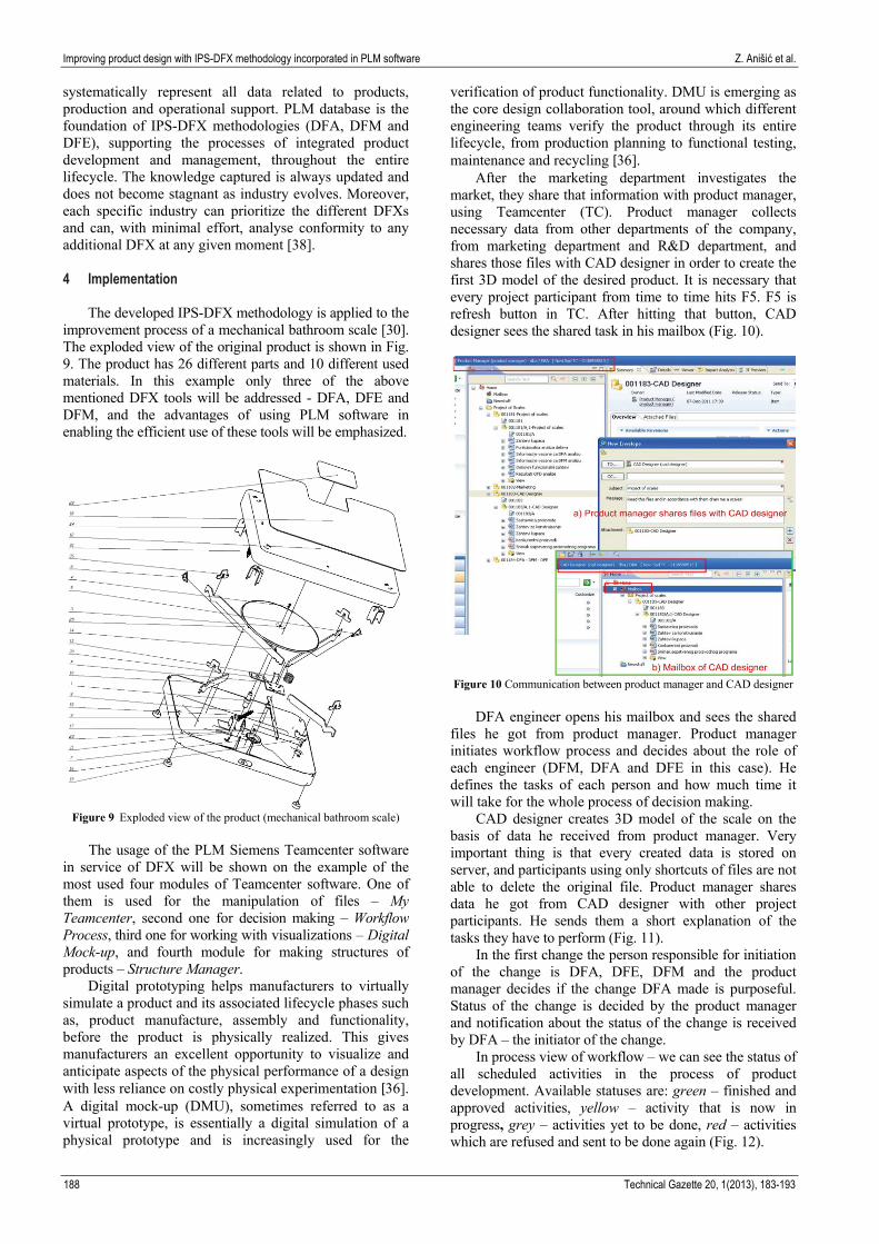
After the marketing department investigates the market, they share that information with product manager, using Teamcenter (TC). Product manager collects necessary data from other departments of the company, from marketing department and R&D department, and shares those files with CAD designer in order to create the first 3D model of the desired product. It is necessary that every project participant from time to time hits F5. F5 is refresh button in TC. After hitting that button, CAD designer sees the shared task in his mailbox (Fig. 10).
Figure 10 Communication between product manager and CAD designer
DFA engineer opens his mailbox and sees the shared
files he got from product manager. Product manager initiates workflow process and decides about the role of each engineer (DFM, DFA and DFE in this case). He defines the tasks of each person and how much time it will take for the whole process of decision making.
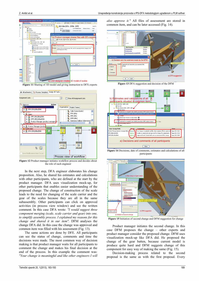
CAD designer creates 3D model of the scale on the basis of data he received from product manager. Very important thing is that every created data is stored on server, and participants using only shortcuts of files are not able to delete the original file. Product manager shares data he got from CAD designer with other project participants. He sends them a short explanation of the tasks they have to perform (Fig. 11).
In the first change the person responsible for initiation of the change is DFA, DFE, DFM and the product manager decides if the change DFA made is purposeful. Status of the change is decided by the product manager and notification about the status of the change is received by DFA – the initiator of the change.
In process view of workflow – we can see the status of all scheduled activities in the process of product development. Available statuses are: green – finished and approved activities, yellow – activity that is now in progress, grey – activities yet to be done, red – activities which are refused and sent to be done again (Fig. 12).
Z. Anišić et al. Unapređenje konstrukcije proizvoda s IPS-DFX metodologijom ugrađenom u PLM softver
Tehnički vjesnik 20, 1(2013), 183-193 189
Figure 11 Sharing of 3D model and giving instruction to DFX experts
Figure 12 Product manager initiates workflow process and decides about
the role of each engineer
In the next step, DFA engineer elaborates his change
proposition. Also, he shared his estimates and calculations with other participants, who are defined at the start by the product manager. DFA uses visualization mock-up, for other participants that enables easier understanding of the proposed change. The change of construction of the scale leads to the need for changing of the scale carrier and the gear of the scales because they are all in the same subassembly. Other participants can click on approved activities (in process view window) and see the written comment. In this case DFA wrote: "I would suggest three component merging (scale, scale carrier and gear) into one, to simplify assembly process. I explained my reasons for this change and shared it in our item". DFM analyses the change DFA did. In this case the change was approved and common item was filled with his assessment (Fig. 13).
The same actions are done by DFE. All participants can see the status of change, comments and time the decisions were made. The most common way of decision making is that product manager waits for all participants to comment the change and makes his final decision at the end of the process. In this example the comment was: "Your change is meaningful and like other engineers I will
also approve it." All files of assessment are stored in common item, and can be later accessed (Fig. 14).
Figure 13 DFA suggestion and decision of the DFM
Figure 14 Decisions, date of comments, estimates and calculations of all
participants
Figure 15 Initiation of second change and DFM suggestion for change
Product manager initiates the second change. In this
case DFM proposes the change – other experts and product manager consider the proposed change. DFM uses visualization mock-up like DFA did. He proposed the change of the gear batten, because current model is produce quite hard and DFM suggests change of this component for easy way of making the same (Fig. 15).
Decision-making process related to the second proposal is the same as with the first proposal. Every

Improving product design with IPS-DFX methodology incorporated in PLM software Z. Anišić et al.
190 Technical Gazette 20, 1(2013), 183-193
participant in process makes his own calculations, estimations, and decisions. Product manager initiates the process where every participant needs to approve the proposal, because only in this way the proposal will be approved as the change. Also, in this case results are the same, second change has been approved. Flags mark approved change by product manager who has the final word on the basis of all made comments. Next, the product manager initiates the third change. In this case DFE proposes the change and other experts and product manager consider the proposed change. The third change (the change of material of the casing – less harmful for the environment) has been approved. Again, flags represent approved change (Fig. 16).
Figure 16 Initiation of the third change and approval of the same
On the basis of all changes product manager makes
the final report. The report with instructions is sent to the CAD designer who will create a new scale, with all demanded changes. The final result of the process is the new design of the product (Fig. 17).
Figure 17 Design of the scale after all the changes made
After all the changes a new model of the scale is
developed. Next step is creating product structure of the new product and comparison with the old one, and making final decision, which is the task for product manager.
PLM and BOM (Bill of Material) have been important since it is necessary to provide many sectors or enterprise information systems with the product information and part list through the whole product lifecycle [39]. The design process derives and generates every BOM for the product before the commencement of production, manufacturing execution and procurement, while the design BOM is divided into BOM groups for production plan, procurement and manufacturing execution. The BOM should also help in the integration of product data and the product structures throughout the product lifecycle. Therefore, it has been used as a hub of product data for product design, production planning, procurement and financial management. Also, it should involve not only part lists but also product data which define the product information [40].
BOM is applicable to many different environments and industries. Any product which can be manufactured has a bill of materials. BOM is product structure that lists the parts and components that constitute the product in the context of an assembly, subassembly, or model. BOMs are known by different names across different industries: a recipe, a formula, an ingredient list, a parts list, packaging specifications, to name a few. Regardless of what it is called in a particular industry, it is a list of parts or items needed to make some product [41].
Figure 18 Comparison of product structures and getting report
In the past, manufacturing industries managed the
BOM for MRP (Material Requirement Planning) and production planning in an attempt to transform the design-BOM to a manufacturing-BOM and procurement BOM. Therefore, the M-BOM (Manufacturing-BOM) was managed as one of the most important ways to provide product information. In the 1980s, the BOM was required by MRP during the production planning stage to cope with scheduled production for the manufacturers [39].

Z. Anišić et al. Unapređenje konstrukcije proizvoda s IPS-DFX metodologijom ugrađenom u PLM softver
Tehnički vjesnik 20, 1(2013), 183-193 191
Product manager compares two structures to identify changes or differences between the two product structures. For example, he: (1) identifies component changes between assemblies; (2) tests for consistency between multiple views of the same item; (3) finds differences between differently configured structures.
Product structures can be compared using one of the following standard modes: (1) single-level mode; (2) multilevel mode; (3) lowest level mode. In this example product manager uses all mode levels to compare two product structures, and make final decision if the new model of scales is really better than the old one.
In the left window (black frame) are product structure parts (components) of old model, and in the right window (green frame) is product structure of the new model of scales. The red fields are used for marking the differences between the product structures and the report can be seen below (Fig. 18).
On the basis of comparison of two product structures and estimates made by participants of the team for product development, product manager will make final decision and reports.
5 Discussion
Even though there are many benefits, the presented research has its limitations. The main are that the IPS-DFX methodology incorporated in the Siemens PLM Teamcenter software has not been tested in manufacturing practice. Furthermore, although authors found that the use of IPS-DFX Methodology with Product Lifecycle Management Software in developed model is appropriate, the use of other methodologies, like SAP PLM rapid-deployment solution, could also be argued.
As well, the next few things the user needs to be careful about when working in Siemens PLM Software – Teamcenter are as follows: once the user enters their login information and enters into the software, it automatically loads the latest changes made by other users. In this software, at least in this version, there is no auto-refresh button for the input data. So there is a good reason that the refresh button is pressed before any decision, or otherwise the decision can be made on the basis of data that are not current.
Considering the decision-making process, especially when the job involves more than 10 participants, it is important to define the time that the decision must be entered, and whether it is required that the decision be unanimous or it is enough that the majority of participants in certain decision-making process agree (for example 70 % or 80 %), so the decision is made. If these things fail during the opening process, it leads to the situation that the entire process is significantly prolonged. Depending on the type of decision-making, it is very important to define whether it is possible that a participant does not agree with the proposal and that all should nevertheless be accepted or it is sufficient that only one participant does not agree with the proposal and that the same be returned immediately to the beginning.
The future work will be focused on implementation of the proposed model in practice and testing of the model’s functionality.
6 Conclusion
Considering the example shown in this paper we can conclude that combining of DFX tools and PLM software solutions leads to: Maintaining of centralized easy accessible product
data base. Easy re-use of existing product structures. Shorter time for product development. Cost saving engineering processes. Fewer mistakes in product development. Better communication between engineering and
management. Transparent product development. Enabled efficient concurrent engineering. Easier to find differences between differently
configured structures. Easier management of engineer change orders (ECO). Better management of product development projects.
With the advent of a PLM system, members can work
together in real time on digital models. A change in design can be immediately communicated to engineering team, who in turn can adjust component requirements, which is communicated to purchasing and budgeting. Since these changes are happening concurrently, the representatives of each department can focus on their tasks as they relate to the entire product. Due to the transparency of the PLM process, employees will be less likely to inadvertently duplicate one another’s work [42].
In this paper PLM systems have been introduced as the support for capturing, analysing and evaluating product, production and operational support data, with the aim to improve complex methodologies such as IPS-DFX (DFA, DFM and DFE). Providing a more substantiated information basis, PLM systems ensure a higher quality if decision making processes, since the relevant data the engineers need for their work are integrated on a common platform with the provision of a single access point. 7 References [1] Zelenovic, D. Production Systems Design. FTN izdavaštvo,
Novi Sad (in serbian), 2003. [2] Suzic, N.; Lazarevic, M.; Sremcev, N. Design for Product
Variety. // 6. Simpozijum o konstruisanju, oblikovanju i dizajnu – KOD/ Palić, Serbia, 2010, pp. 219-222.
[3] Stefanic, N.; Gjeldum, N.; Mikac, T. Lean concept application in production business. // Technical Gazette, 17, 3 (2010), pp. 353-356. ISSN 1330-3651.
[4] Ulrich, K.; Eppinger, S. Product design and development. McGraw Hill, 2003.
[5] Hauschild, M.; Wenzel, H.; Alting, L. Life cycle design – a route to the sustainable industrial culture? // Annals of the CIRP 48, 1(1999), pp. 393-396.
[6] Kuo, T. C.; Huang, S. H.; Zhang, H. C. Design for Manufacture and Design for X: Concepts. // Applications and Perspectives Computers and Industrial Engineering, 41, 3(2001), pp. 241–260.
[7] Cosic, I.; Anisic Z.; Firstner, I. Design for Environment in IPS-DFx Methodology for Integrated Product Development as a Part of Concurrent Engineering. // 1st Serbian-Hungarian Joint Symposium on Intelligent System/ Subotica, Serbia, 2003, pp. 101- 113. ISBN 9637154191.

Improving product design with IPS-DFX methodology incorporated in PLM software Z. Anišić et al.
192 Technical Gazette 20, 1(2013), 183-193
[8] Hauschild, M.; Jeswiet, J.; Alting, L. From Life Cycle Assessment to Sustainable Production: Status and Perspectives. // Manufacturing Engineering, 3, 2(2005), pp.1-21.
[9] Firstner, I.; Anisic, Z. Design for Environment as a Part of the IPS-DFx Methodology for Integrated Product Development. // Annals of the Faculty of Engineering Hunedoara, 3, 2(2005), pp. 117- 124, ISSN 1584-2673.
[10] Andreasen, M.M. Design for Assembly. Springer-Verlag, New York, USA, 1988.
[11] Mandić, V.; Cosic, P. Integrated product and process development in collaborative virtual engineering environment. // Technical Gazette, 18, 3(2011), pp. 369-378. ISSN 1330-3651.
[12] Paasivaara, M. Communication in Networked Product Development – A Case Study. Licentiate thesis. Helsinki University of Technology, Espoo, 2001.
[13] Huang, G. Q.; Mak, K. L. Web-Based Design for X for Collaborative Product Development. 1998. URL: http://www.hku.hk/rss/res_proj/10/10.htm. (14.07.2003).
[14] Siemens. Defining PLM. 2011. URL: http://www.plm.automation.siemens.com/en_us/plm/definition
[15] Sremcev, N.; Suzic, N.; Anisic, Z.; Gecevska, V. Improving Product Design Efficiency Using DFX Tools in PLM Surroundings. // KOD conference/ Balaton, Hungary, 2012, pp. 79-84.
[16] Stark, J. PLM: 21st century Paradigm for Product Realisation. Springer-Verlag, Berlin, 2004.
[17] Saaksvuori, A.; Immonen, A. Product Lifecycle Management. Berlin: Springer-Verlag, 2008.
[18] Grieves, M. Back to the Future: Product Lifecycle Management and the Virtualization of Product Information. // Product Realization – A Comprehensive Approach, Scientific Book. Editors: Tomovic, M.; Wang, S. Springer, 2009, pp. 39-51.
[19] Gecevska, V.; Chiabert, P.; Anisic, Z.; Lombardi, F.; Cus, F. Product lifecycle management through innovative and competitive business environment.// Journal of Industrial Engineering and Management, 3, 2(2010), pp. 323-336.
[20] Cosic, I.; Anisic, Z.; Firstner, I.; Lalic, B. Design for Environment as a Part of the IPS-DFX Methodology for Integrated Product Development. // International Symposium Interdisciplinary Regional Research (ISIRR)/ Novi Sad, Serbia, 2007.
[21] Anisic, Z. Istraživanje uticaja integralnog razvoja proizvoda na tehnološke strukture u montaži i određivanje potrebnog nivoa automatizacije. Doctoral dissertation (in Serbian). Fakultet tehničkih nauka, Novi Sad, 2002.
[22] Bernard, A.; Tichkiewitch, S. Design of Sustainable Product Life Cycles. Berlin: Springer-Verlag, 2008.
[23] Vezzetti, E.; Moosa, S.; Kretli, S. Product lifecycle management methodology for supporting knowledge reuse in the consumer packaged goods domain. // Computer-Aided Design 43, 12(2011), pp. 1902-1911.
[24] Stankovski, S.; Lazarević, M.; Ostojić, G.; Ćosić, I.; Purić, R. RFID Technology in Product/Part Tracking During the Whole Life Cycle, Assembly Automation.// International Journal of Assembly Technology and Management, 29, 4(2009), pp. 364-370. ISSN 0144-5154.
[25] Lazarević, M.; Ostojić, G.; Ćosić, I.; Stankovski, S.; Vukelić, Đ.; Zečević, I. Product lifecycle management (PLM) methodology for product tracking based on radio-frequency identification (RFID) technology. // Scientific Research and Essays, 6, 22(2011), pp. 4776-4787. ISSN 1992-2248.
[26] Firstner, I. Razvoj metodologije za povezivanje činilaca u procesu integralnog razvoja proizvoda u umreženom okruženju. Master Thesis (in Serbian), Fakultet tehničkih nauka, Novi Sad, 2005.
[27] Boothroyd, G.; Dewhurst, P.; Knight, W. Product Design for Manufacture and Assembly. University of Rhode Island, Kingston, 1994.
[28] Feng, S. C.; Song, E. Y. Information Modelling of Conceptual Process Planning Integrated with Conceptual Design. // The 5th Design For Manufacturing Conference in the 2000 ASME Design Engineering Technical Conferences/ Baltimore, Maryland, 2000, Paper Number DETC00/DFM-14009.
[29] Yarwood, J. M.; Eagan, P. D. Design for Environment. Minnesota Office of Environmental Assistance, Saint Paul, Minnesota, 2000.
[30] Firstner, I.; Anisic, Z.; Cosic, I. Integrated Product Development in Internet Surroundings. // DAAAM International Scientific Book. Editor: Katalinic, B. Vienna, Austria: DAAAM International Vienna, 2005, pp. 179-192. ISBN 3-901509-43-7.
[31] Ebert, C.; Man, J. D. Effectively utilizing project, product and process knowledge. // Information and Software Technology, 50(2008), pp. 579-594.
[32] Furstner, I.; Anisic, Z.; Cosic, I. Overview of Current Research Results of Mass Customization.// 3rd Int. Conference on Mass Customization and Personalization in Central Europe/ Palic, Serbia, 2008, pp. 65-73.
[33] Merminod, V.; Rowe, F. How does PLM technology support knowledge transfer and translation in new product development? Transparency and boundary spanners in an international context. // Information and Organization, 22, 4(2012), pp. 295-322.
[34] Ameri, F.; Dutta, D. Product Lifecycle Management: Closing the Knowledge Loops. // Computer-Aided Design & Applications, 2, 5(2005), pp. 577-590.
[35] Grieves, M. PLM: Driving the Next Generation of Lean Thinking. New York: McGraw-Hill, 2009.
[36] Maropoulos, P. G.; Ceglarek, D. Design verification and validation in product lifecycle. // CIRP Annals - Manufacturing Technology, 59, 2(2010), pp. 740-759.
[37] Bufardi, A.; Edler, A.; Frey, M.; Kiritsis, D.; Metin, A.; Smith, B. Improving Product Development by Design-for-X (DfX) Support. // The Future of Product Development, Scientific Book, Proceedings of the 17th CIRP Design Conference. Editor: Krause, F.L. Springer, 2007, pp. 75-84.
[38] Molcho, G.; Zipori, Y.; Schneor, R.; Rosen, O.; Goldstein, D.; Shpitalni, M. Computer aided manufacturability analysis: Closing the knowledge gap between the designer and the manufacturer. // CIRP Annals - Manufacturing Technology 57, 1(2008), pp.153–158.
[39] Lee, J. H.; Kim, S. H.; Lee, K. Integration of evolutional BOMs for design of ship outfitting equipment. // Computer-Aided Design, 44, 3(2012), pp. 253-273.
[40] Anisic, Z.; Krsmanovic, C. Assembly Initiated Production as a Prerequisite for Mass Customization and Effective Manufacturing. // Strojniski vestnik - Journal of Mechanical Engineering, 54, 9 (2008), pp. 607-618, UDC 658.5
[41] Weiler, K. Topological structures for geometric modeling. Doctoral dissertation. Rensselaer Polytechnic Institute, 1986.
[42] CIMdata. PDM to PLM: Growth of an industry. 2003. URL: http://www.cimdata.com. (04.03.2003).
Z. Anišić et al. Unapređenje konstrukcije proizvoda s IPS-DFX metodologijom ugrađenom u PLM softver
Tehnički vjesnik 20, 1(2013), 183-193 193
Authors' addresses: Zoran Anišić, Associate Professor Faculty of Technical Sciences Trg Dositeja Obradovica 6 21000 Novi Sad, Serbia E-mail: [email protected] Ivica Veža, Full Professor Faculty of Electrical, Mechanical and Naval Engineering Ruđera Boškovića bb 21000 Split, Croatia E-mail: [email protected] Nikola Suzić, M.Sc. Assistant Faculty of Technical Sciences, Trg Dositeja Obradovica 6 21000 Novi Sad, Serbia E-mail: [email protected] Nemanja Sremčev M.Sc. Assistant Faculty of Technical Sciences, Trg Dositeja Obradovica 6 21000 Novi Sad, Serbia e-mail: [email protected] Anja Orčik, Doctoral Candidate Faculty of Technical Sciences, Trg Dositeja Obradovica 6 21000 Novi Sad, Serbia E-mail: [email protected]