Natural extension to ordinary DP functionality Controls the vessel along a track of predefined waypoints Different heading and speed control modes available
AB
C
A
B
Presenter
Presentation Notes
Scope of talk: Path generation, speed profile and tracking analysis User interface examples
Applicable (in parts) to high-speed tracking schemes
Reference systemPath generatorSpeed profile
Etc
Estimator
Control lawFeedback
FeedforwardThruster Allocation
Estimated vessel states
Forces and moment,setpoint
Pos/hdg setpoint
Velocity setpoint
Processed measurements
Operatoractions
External wpt source
Presenter
Presentation Notes
Thruster allocation based on centre of gravity: moments and forces are computed wrt that point. Thus, control law follows and reference input signals must be wrt centre of gravity.
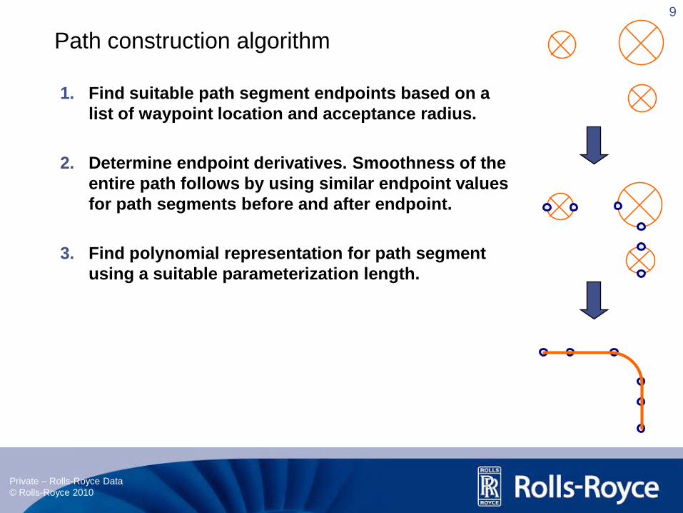
What is a parameterized path? Benefits? Path geometry, derivatives Some path information available Curvature is the derivative of the tangent. Curvature is easy to find for inscribed circles, it’s simply 1/R. Straight line: curvature = 0. When we get to other paths, it’s not so straight-forward. The information about the waypoint, CR and CO path and their derivatives let us: Know properties of paths for centre of rotation, centre of gravity and waypoint table. Verify path construction Check that chosen offset is ok (depending on track construction strategy)
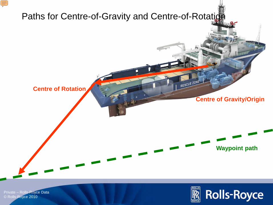
Paths for Centre-of-Gravity and Centre-of-Rotation
Waypoint path
Centre of RotationCentre of Gravity/Origin
Presenter
Presentation Notes
Reference point located outisde vessel’s centre of gravity and centre of rotation. Follows waypoint path Thrust allocation is based on controlling the surge and sway forces and yaw moment in CG. Thruster commands are given with respect to the centre of gravity Effect on path creation for these two points Pictures with applications
Since waypoint path are smooth and path derivates are continuous, the CG and CR path will also be smooth. R( ) is simply a rotation matrix and is perfectly smooth. Applications CR location, offset examples Animations of path creation Path parameter theta is the same variable in all equations so it’s easy to find corresponding path information. The information about the waypoint, CR and CO path and their derivatives let us: Know properties of paths for centre of rotation, centre of gravity and waypoint table. Verify path construction Check that chosen offset is ok (depending on track construction strategy)
Dynamic assignments on path: keep constant speed along path, maintain a steady speed minutes be at waypoint at time , complete track at minimum time, and specified force for acceleration/braking
Speed assignment for reference point affects speed on CR and CG path
Spee
d
Distance
CO path
Wpt path
Normal offset
v [m/s]
v [m/s]
v
v v
> v
Speed ProfileWpt path
Speed ProfileCO path
Wheel-Over Point
Presenter
Presentation Notes
Speed profile Analytical Different dynamic assignments Path speed assignment effect on other tracks Heading change complicate matters!
New information enable us to: find speed and acceleration values on all paths analyze path speed profile against limiting factors for entire waypoint, CR, and
CO path. detect conflicts between simultaneous operations calculate new speed setpoints to eliminate conflicts
Some limiting factors vessel speed in turns, rotation during heading change, vessel speed/acceleration/rate limits, reference point limits
Presenter
Presentation Notes
analyze path speed profile (certain speed/acceleration values) against limiting factors for entire waypoint, CR, and CO path. detect potential conflicts between simultaneous operations, e.g., heading change during a turn and keeping maximum speed on track Motivation What do we gain? Limiting factors Dynamic limits for the reference point along the waypoint path Solutions are found analytically and are thus available instantly, eliminating the need for algorithms that involve searching and trial-and-error.
Steer reference model along path with given speed profile
Reference model is inaccurate compared to real-life Vessel state feedback needed Design mechanisms that ensures path parameter progress keeps up with vessel
Spee
d
Presenter
Presentation Notes
Examplify: If theta is parameterized in meters, and vp is constant 1 m/s, then after 225 seconds the reference position is here... And after 750 seconds we have reached wpt 4
Present some examples of our design principles in low-speed waypoint tracking application Safety: The tracking user interface has tried to give the operator as much freedom of choice as possible and preparing for errors by: Minimize chance of errors occurring Minimize impact if errors occur Performance: DP tracking performance: control law, reference system Simplicity: Easy to start operation, do different procedures during operation Familiar interfaces provides operator with key information for that specific operation Proximity: Minimize number of keystrokes Maximize number of commands available at your fingertips Proximity:
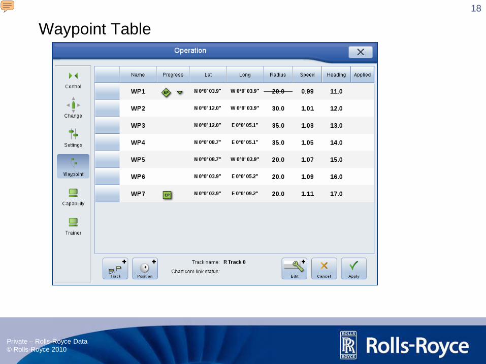
A waypoint tracking operation starts by loading the waypoints into the waypoint table. From here you can make changes to values for each specific waypoint. You can also save and load a track from and to a file, rename your track or load a new track from a chart system. Whenever a change has been made to a waypoint, a yellow marker will appear in the “Applied” column. If the change made resulted in an invalid track, the marker will be red. Path analysis methods determine the track validity. Changes are approved by pressing the “Apply” button.
Path analysis from the previous section makes it easy to quickly analyze changes to the path. If the operator makes changes that cause an invalid path (e.g., two waypoints are too close, new offset value is too large), the edit path will be shown in red and it will be impossible to apply the changes. In addition, the waypoint(s) with invalid settings will be marked in the waypoint table. Note that the head’s-up-displays (HUDs) change after the tracking operation has started. The HUDs supply the user with what we have identified as key knowledge for the current operation. During a tracking operation the user sees information about track progress, speed setpoints in turns and on straight line segments, track deviation and chosen offset values. The reference speed in turns may vary from straight line segments due to path curvature, heading change operations and vessel speed limitations. The maximum allowable speed through a turn is calculated in a similar manner to the example in the previous section. We aim to incorporate a what-you-see-is-what-you-get principle in the user interface. Changes to the waypoint geometry or offset vector are shown instantly as a yellow edit curve on the 3D scene and provides visual feedback. During tracking operations, the transition from the current highway to the new edit curve is shown. The shape depends on the current along-path speed and the selected offset speed. After applying the changes the yellow edit path becomes the new highway to be followed.
Some situations must of course be handled manually. The way-point tracking will go into a fault state if one of the following conditions occurs: All position reference systems lost (causes dead reckoning). All heading sensors lost, (will also cause dead reckoning). No thruster forces in surge, sway or yaw. When going into the fault state the controller will try to stop the vessel: speed set points are set to zero and when model estimated speed has reached zero, the controller will try to keep the estimated position. When thruster forces are available in 3 DOF and position reference systems and heading sensors are OK the system leaves the fault state. If the vessel has drifted of more than 3 meter from last known position on track (or more than 3 degrees), a dialog box will pop up with two selections, continue or exit tracking. The yellow curve will appear and show the route back to track. The operator must then decide what to do next.