improve standard operating procedure for the x...
TRANSCRIPT

IMPROVE X-Ray Fluorescence Analysis
SOP 301, Version 2.1
Date: October 1, 2015
Page 1 of 17
IMPROVE Standard Operating Procedure
for the X-Ray Fluorescence Analysis
of Aerosol Deposits on PTFE Filters
(with PANalytical Epsilon 5)
SOP 301
IMPROVE Program
Crocker Nuclear Laboratory
University of California, Davis
Original Version (Version 2.0)
Prepared By: __ Sinan Yatkin __ __ ___ Date: _1/17/2014
Reviewed By: __ Krystyna Trzepla _________ Date: _1/17/2014
Approved By: _ Charles E. McDade _ _ Date: _1/17/2014
Latest Version (Version 2.1)
Updated By: __ Sinan Yatkin ___ _ _ Date: _10/1/2015
Reviewed By: __ Krystyna Trzepla ______ __ Date: _1/10/2016
Approved By: _ _Charles E. McDade _ _ Date: _1/10/2016

IMPROVE X-Ray Fluorescence Analysis
SOP 301, Version 2.1
Date: October 1, 2015
Page 2 of 17
DOCUMENT HISTORY
Version No.
Date Modified
Initials Section/s Modified
Brief Description of Modifications
2.1 10/1/2015 SY/KT Section 9 and 11 A table including the calibration verification activities, criteria and corrective actions was added to Section 9.
A table including the routine QA/QC activities, criteria and corrective actions was added to Section 11.
QA/QC procedure was updated introducing the new webapp for charting/visualization of QC data.
IMPROVE X-Ray Fluorescence Analysis
SOP 301, Version 2.1
Date: October 1, 2015
Page 3 of 17
Table of Contents 1. PURPOSE AND APPLICABILITY ..................................................................................................... .4
2. SUMMARY OF THE METHOD ....................................................................................................... .4
3. DEFINITIONS ................................................................................................................................ .5
4. HEALTH AND SAFETY WARNINGS ................................................................................................ .6
5. CAUTIONS .................................................................................................................................... .6
6. INTERFERENCES AND POSSIBLE SOURCES OF ERROR.................................................................. .7
7. PERSONNEL QUALIFICATIONS, DUTIES, AND TRAINING.............................................................. .7
8. EQUIPMENT AND SUPPLIES ......................................................................................................... .8
9. PROCEDURAL STEPS..................................................................................................................... .8
9.1 Set up and turn on analyzer……………………………………………………………………………………………….8
9.2 Calibration…………………………………………………………………………………………………………………………8
9.3 Daily (or weekly) operation……………………………………………………………………………………………….10
9.4 Loading and removing filters…………………………………………………………………………………………….11
10. DATA AND RECORDS MANAGEMENT ........................................................................................ 12
10.1 Log books.………………………………………………………………………………………………………………...……12
10.2 Transferring data from the Epsilon 5 to the SQL data base………………………………………………12
10.3 Formatting data for further processing……………………………………………………………………………12
10.4 Calculation of mass loadings, Minimum Detectable Limits (MDLs), and uncertainties…….12
11. QUALITY ASSURANCE AND QUALITY CONTROL......................................................................... .14
11.1 Performance testing, control charts, tolerances and actions to be taken …………………….…15
11.2 Reproducibility testing…………………………………………………………………………………………………….16
11.3 Data Validation………………………………………………………………………………………………………………..16
11.4 Approval of data for final validation and delivery ……………………………………………………………17
12. REFERENCES ............................................................................................................................... ..17
List of Tables
Table 1. Epsilon 5 setup for IMPROVE samples…………………………………………………………………………..5
Table 2. Standards and reference materials used for calibration of Epsilon 5…………………………….9
Table 3. The calibration verification activities, criteria and corrective actions……………………………10
Table 4. The routine QA/QC activities, criteria and corrective actions………………………………………..14
List of Figures
Figure 1. PANalytical Epsilon 5 analyzer and computer station in the XRF Laboratory at CNL……….8
Figure 2. Figure 2. Performance testing with ME reference material: daily monitoring of Fe mass loadings with warning (±3%, grey lines) and acceptance (±5%, out of scale) limits.………..16
IMPROVE X-Ray Fluorescence Analysis
SOP 301, Version 2.1
Date: October 1, 2015
Page 4 of 17
1. PURPOSE AND APPLICABILITY
This standard operating procedure (SOP) provides an overview of the principles of X-Ray Fluorescence (XRF) spectrometry, describes the application of this technique to determine and quantify the elemental composition of IMPROVE aerosol samples using the PANalytical Epsilon 5 XRF analyzer, and outlines the laboratory procedures. The procedures cover operational safety, analyzer calibration and monitoring, filter preparation, handling and analysis, data acquisition, and quality control for all IMPROVE aerosol filter samples.
The body of this document gives only the outline of how samples are handled and analyzed and how data are processed and validated. Each step in the filter analysis process has a specific function and a set of procedures. A detailed explanation of each of these steps is required and is provided in the Technical Information (TI) documents that are referenced within this SOP. The PANalytical Epsilon 5 analyzer manual is referenced for more specific instructions on certain processes. 1
Three PANalytical Epsilon 5 XRF analyzers are housed in Crocker Nuclear Laboratory (CNL, Jungerman Hall) at the University of California, Davis.
2. SUMMARY OF THE METHOD
Analysis of IMPROVE aerosol filter samples is performed using energy dispersive X-ray fluorescence systems, specifically the Epsilon 5 XRF analyzers operating under vacuum. The basis of the method is the interaction of X-ray photons from the analyzer’s excitation source with atoms of the elements present in the filter deposit.
The source of X-rays in the PANalytical Epsilon 5 analyzer is a 100 kV side window x-ray tube with a dual Scandium (Sc)/Tungsten (W) anode. Generated X-rays are focused on one of seven secondary targets in such geometry that polarized X-ray photons are used to excite a sample. These photons cause the ejection of inner shell electrons from the atoms in the sample. The vacancies are filled with outer shell electrons and the transitions result in the emission of X-rays, which are characteristic of each element present in the sample. These characteristic X-rays are detected in a solid state Germanium (Ge) X-ray detector. Electrical charges generated by each entering detector photon are grouped into energy channels, counted and displayed during analysis as a sample spectrum of X-ray counts versus energy. The characteristic peaks in the spectrum are superimposed on a background caused by the scatter of X-rays from the tube into the detector. The individual peak energies in the spectrum correspond to specific elements and peak areas are proportional to elemental mass loadings (although the relationships can become non-linear at high concentrations). Each spectrum is collected for the specified time and saved for further processing with the Epsilon 5 software. Spectrum evaluation is done by non-linear least squares fitting based on the AXIL algorithm.2
The Epsilon 5 is a fully integrated spectrometer exceling in high-throughput, high-sensitivity analysis for multiple elements. The high power excitation source and polarizing optical path provide low detection limits for many elements allowing analysis of small quantities of sample. The system’s gain correction method assures high analyzer stability; therefore the calibrations can be done less frequently. Because XRF is a non-destructive technique, the samples can be reanalyzed multiple times. However, exposure to the vacuum may result in the loss of some volatile species (i.e. ammonia, nitrate, chlorine, bromine).
For the IMPROVE samples, seven different analytical conditions are used during a single analysis run to balance sensitivity and exposure time for the 24 elements reported to IMPROVE. Each analytical condition is

IMPROVE X-Ray Fluorescence Analysis
SOP 301, Version 2.1
Date: October 1, 2015
Page 5 of 17
designed to optimize detection for a subset of the 24 elements and uses a different secondary target, X-ray tube voltage and current, energy detection range and resolution setting, and exposure time (see Table 1).
Table 1. Epsilon 5 setup for IMPROVE samples
Secondary Target Analysis Time, s kV mA Detector Setting Reported Elements
CaF2 600 40 15 High Resolution Na, Mg, Al, Si, P,S, Cl, K Fe 400 75 8 Standard Ca, Ti, V, Cr Ge 300 75 8 Standard Mn, Fe, Ni, Cu, Zn KBr 300 100 6 Standard As SrF2 300 100 6 Standard Se, Br Mo 300 100 6 Standard Rb, Sr, Pb
Al2O3 200 100 6 Standard Zr
3. DEFINITIONS
Thin sample: A sample with a deposit thin enough for enhancement and absorption phenomena to be negligible.
EDXRF – Energy Dispersive X-ray Fluorescence: An analytical technique used to determine the elemental content of a sample.
Reanalysis: Periodic analysis of selected IMPROVE samples to check the stability of the analyzers.
Reference materials: Samples used to evaluate the performance of the XRF analyzers. The mass loadings of reference materials have assigned mass loadings, although the mass loadings are not necessarily assigned (or certified) by an authority. Reference materials can be samples obtained from authoritative agencies such as the National Institute of Standards and Technology (NIST), samples produced by private companies or ambient air quality samples that are assigned as reference materials and analyzed multiple times.
Standard Reference Material (Standards): Reference materials with certified reference mass loadings and uncertainties. Standards are used to calibrate the XRF analyzers.
Intensities: The flux of emitted radiation at a particular wavelength. Intensities are quantified in units of counts per second per milliamp (cps/mA). Intensities are often referred to informally as counts.
Theoretical intensities: The expected flux of emitted radiation by standard reference materials computed from the certified mass loadings and the library of fundamental parameters.
Raw intensities (referred to as “net intensities” in the PANalytical software): The fluorescence intensities (cps/mA) measured and deconvoluted by the analyzer. These raw intensities construct a spectrum for each analyzed sample.
Deconvolution: The mathematical processing to resolve the contributions of individual elements to the measured spectrum. An iterative least-squares method is used to fit theoretical profiles to the measured spectrum, constrained by known theoretical ratios between different lines from the same element. Element raw intensities (cps/mA) are quantified by the deconvolution process.
Net intensities (referred to as “corrected intensities” in the software): The deconvoluted and blank-corrected fluorescence intensities (cps/mA) calculated by the analyzer. The net intensities are per element and are used along with the calibration factors to calculate the mass loadings in the IMPROVE samples.
XRF Application: The collection of software and hardware setting used to analyze samples including the analytical operating parameters (secondary targets, times of analysis, X-ray tube
IMPROVE X-Ray Fluorescence Analysis
SOP 301, Version 2.1
Date: October 1, 2015
Page 6 of 17
operational parameters, detector settings, reported elements), deconvolution parameters, and calibration factors for analyzing samples.
4. HEALTH AND SAFETY WARNINGS
The Epsilon 5 is designed for safe operation. The XRF analysis is conducted in a radiation-sealed environment with interlocks that do not allow the operator to access the X-ray chamber while the X-ray tube is on. The analyzers are also inspected and certified by the Office of Environmental Health and Safety (EH&S) at UC Davis. Nevertheless, the following cautions should be noted.
The Epsilon 5 analyzers produce X-rays which can be hazardous to health if precautions are not taken. Refer to the Epsilon 5 System User’s Guide for more information (Chapter 3, pg. 7).
A Beryllium (Be) window is present in the analyzer (X-ray tube and Ge detector). Fumes or the dust from beryllium and its compounds can be hazardous if inhaled. The reader is referred to the Epsilon 5 System User’s Guide (Chapter 3, pg. 8) and to Attachment 1. The window is fragile and should not be touched or exposed to any pressure, which may cause a rupture. If a rupture occurs, extreme caution has to be exercised during the cleanup (consult a service engineer and EH&S).
Lead may be found as a shielding material in the Epsilon 5. Fumes or dust from lead can be hazardous if inhaled or ingested. For further information, the reader is referred to the System User’s Guide (Chapter 3, pg. 9).
Liquid nitrogen is used to cool the Pan-32 Ge X-ray detector. It should be handled with care in well-ventilated rooms. Liquid nitrogen and nitrogen gas are not toxic. However, they may displace atmospheric oxygen when present in large quantities or when used in confined or poorly ventilated spaces, resulting in a suffocation hazard. For further details on precautions when using liquid nitrogen and emergency actions in the event of a nitrogen leak, the reader is referred to the Epsilon 5 System User’s Guide (Chapter 3, page 10-11) and to Attachment 1.
Do not remove or open any panels that are not accessible by hand. Terminals may be live when the machine is connected to its power supply, and accessing these areas is likely to expose live parts. For further details, please refer to the Epsilon 5 System User’s Guide (Chapter 3, page 7).
5. CAUTIONS
The system user must be aware that changing any of the analyzer controls during a measurement (e.g., medium, high tension generator, target and filter selections, and/or sample handling) will influence the analysis results. Analyzer parameters and settings can also be changed in the software, which can influence the analysis results.
No calculations or any other modifications to the running (active) application should be attempted.
The analyzer’s cover allowing access to the sample changing table can be opened only when the green light on the front panel is ON.
The analyzer can be switched off only for a short period of time (<2 hours) without a full restart. In this case the detector and generator high voltage should be kept ON. If the analyzer needs to be shut down for a longer period of time, the shut down and start up procedures specified in the Epsilon 5 System User’s Guide need to be followed.
IMPROVE X-Ray Fluorescence Analysis
SOP 301, Version 2.1
Date: October 1, 2015
Page 7 of 17
6. INTERFERENCES AND POSSIBLE SOURCES OF ERROR
All spectra from IMPROVE samples and field blanks are processed with the PANalytical Epsilon 5 peak deconvolution software, and raw intensities are determined for each element identified by the analyzer. Raw intensities are then blank corrected to account for background contamination from the filter substrate and spectral noise. Sample or reference material intensities are corrected for any fluorescence resulting from the sample media itself by subtracting blank media raw intensities from the sample raw intensities.
Before being used in the network, contamination levels in a new lot of filters are evaluated through acceptance testing (see TI 251C). While small amounts of contaminants can be corrected with blank subtraction, large amounts of contaminant lead to concerns about the quality of the filter material. Also, variable amounts of contaminants will cause higher uncertainties in the measurements. New lots that fail acceptance testing are returned to the manufacturer for replacement.
The IMPROVE network routinely speciates only fine-particle samples, for which the attenuation of the fluorescent signal by within-particle absorption is minor for most elements. No attenuation correction for particle size or mass loading is performed at this time.
The X-ray beam is almost circular with a diameter of approximately 20 mm. The assumed area of the deposit on 25 mm polytetrafluorethylene (PTFE) filters for IMPROVE is 3.53 cm2 (21 mm diameter), and the deposit is assumed to be homogeneous. Any effects of inhomogeneity are minimized by utilizing the sample spinner, which spins the sample during the analysis at a rate of approximately 3 rpm.
Damaged filters are not analyzed because results can be affected by changes in distance between the sample and the X-ray tube and detector.
7. PERSONNEL QUALIFICATIONS, DUTIES, AND TRAINING
Only trained personnel listed in the MUA (Machine Use Authorization) can operate the Epsilon 5 analyzers. Any adjustments to the Epsilon 5 analyzer settings can be performed only by the laboratory manager or by a delegated person with the laboratory manager’s approval.
Sample handling, including loading and unloading of the Epsilon 5 analyzers can be performed by an employee who has been trained by an authorized user and has read this SOP and associated documents. All users must have taken the Analytical X-Ray Safety Course offered through EH&S, in order to receive a dosimeter (badge and ring). The dosimeter must be worn while loading and unloading samples for analysis.
In order to perform the liquid nitrogen fills, users should obtain relevant training and complete the Cryogenic Safety course available through EH&S.
The preparation of the filters for analysis and regular servicing of the analyzers, including weekly liquid nitrogen fills and detector calibration (automated) is the responsibility of lab technicians. Analyzer calibrations, quality control data evaluation (performed daily, weekly and monthly), and review of the data are the responsibility of the spectroscopist and laboratory manager. The duties of each of these positions are described below:
The Laboratory Manager will
oversee the XRF analysis
approve schedules for routine analysis and special studies
approve and oversee systems calibrations
IMPROVE X-Ray Fluorescence Analysis
SOP 301, Version 2.1
Date: October 1, 2015
Page 8 of 17
oversee maintenance and repair of the XRF analyzers
resolve any inconsistencies in calibrations, reanalyses, or normal analyses
approve the release of the final XRF data
The Spectroscopist will
review the results of all quality control tests
review each data set in the context of historical data and of current system conditions
identify abnormalities and provide recommendations for understanding and rectifying them
perform systems calibrations as needed
The Laboratory Technician will
load and unload filter samples to and from the XRF analyzers
transfer trayfiles to the analyzers and analysis data from the analyzers
perform regular calibration checks and other QC checks
fill the analyzers’ liquid nitrogen reservoirs weekly
8. EQUIPMENT AND SUPPLIES
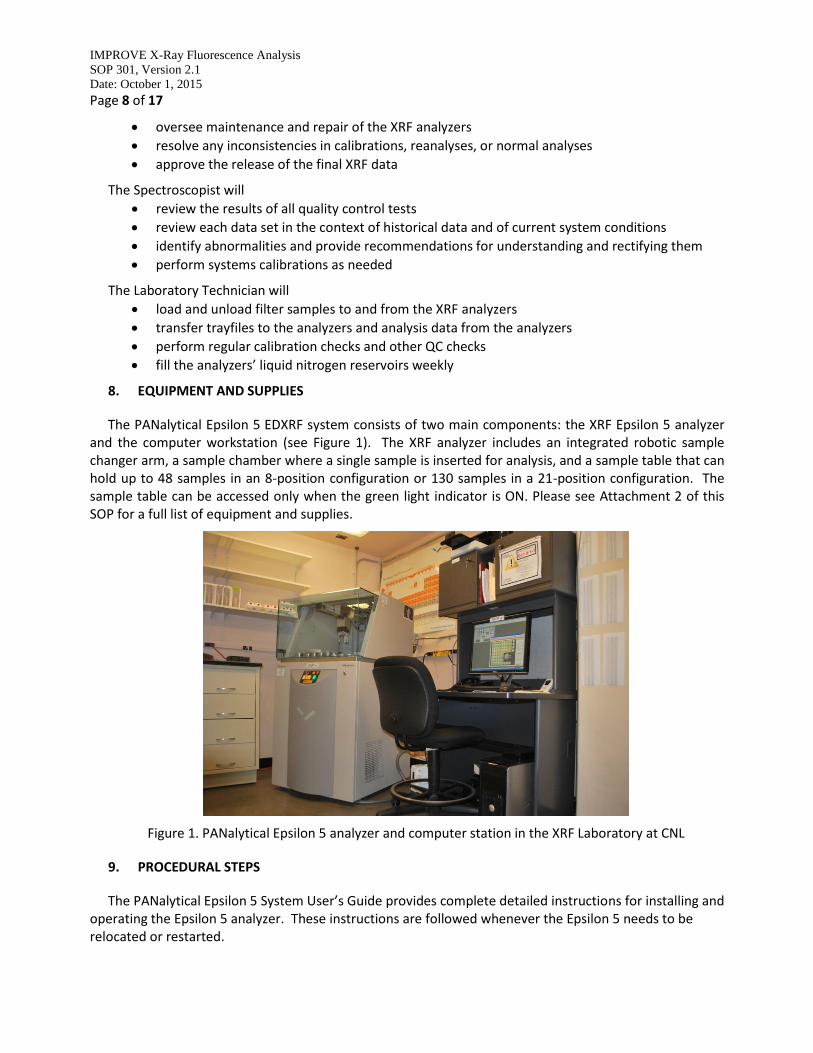
The PANalytical Epsilon 5 EDXRF system consists of two main components: the XRF Epsilon 5 analyzer and the computer workstation (see Figure 1). The XRF analyzer includes an integrated robotic sample changer arm, a sample chamber where a single sample is inserted for analysis, and a sample table that can hold up to 48 samples in an 8-position configuration or 130 samples in a 21-position configuration. The sample table can be accessed only when the green light indicator is ON. Please see Attachment 2 of this SOP for a full list of equipment and supplies.
Figure 1. PANalytical Epsilon 5 analyzer and computer station in the XRF Laboratory at CNL
9. PROCEDURAL STEPS
The PANalytical Epsilon 5 System User’s Guide provides complete detailed instructions for installing and operating the Epsilon 5 analyzer. These instructions are followed whenever the Epsilon 5 needs to be relocated or restarted.
IMPROVE X-Ray Fluorescence Analysis
SOP 301, Version 2.1
Date: October 1, 2015
Page 9 of 17
9.1 XRF Application Setup
In order to start analyzing samples on the Epsilon 5 analyzer, a specific application needs to be developed and set up. Setting up the application requires selecting the elements to be reported, acquisition and reporting scheme conditions, a calibration standards file along with measurement of standards, and deconvolution parameters. As long as no changes are made to the processing methods for a given application, the theoretical intensities of the standard reference materials remain valid. The basic application settings used for the routine IMPROVE sample analyses are shown in Table 1.
9.2 Calibration
The Epsilon 5 has been shown to be a stable analyzer that does not need frequent calibrations. Calibrations are performed upon first installation, approximately yearly or when the analyzer fails verification tests, and whenever an analysis-critical component (e.g., x-ray source or detector) of the analyzer is maintained or replaced.
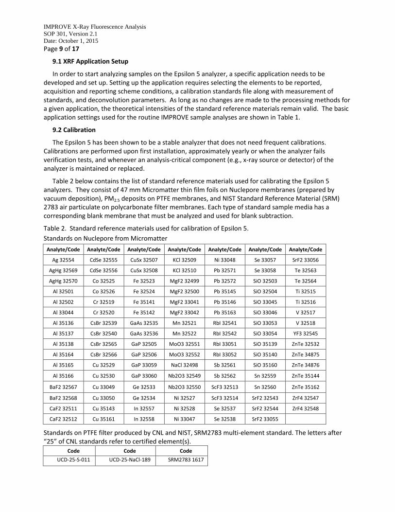
Table 2 below contains the list of standard reference materials used for calibrating the Epsilon 5 analyzers. They consist of 47 mm Micromatter thin film foils on Nuclepore membranes (prepared by vacuum deposition), PM2.5 deposits on PTFE membranes, and NIST Standard Reference Material (SRM) 2783 air particulate on polycarbonate filter membranes. Each type of standard sample media has a corresponding blank membrane that must be analyzed and used for blank subtraction.
Table 2. Standard reference materials used for calibration of Epsilon 5.
Standards on Nuclepore from Micromatter
Analyte/Code Analyte/Code Analyte/Code Analyte/Code Analyte/Code Analyte/Code Analyte/Code
Ag 32554 CdSe 32555 CuSx 32507 KCl 32509 Ni 33048 Se 33057 SrF2 33056
AgHg 32569 CdSe 32556 CuSx 32508 KCl 32510 Pb 32571 Se 33058 Te 32563
AgHg 32570 Co 32525 Fe 32523 MgF2 32499 Pb 32572 SiO 32503 Te 32564
Al 32501 Co 32526 Fe 32524 MgF2 32500 Pb 35145 SiO 32504 Ti 32515
Al 32502 Cr 32519 Fe 35141 MgF2 33041 Pb 35146 SiO 33045 Ti 32516
Al 33044 Cr 32520 Fe 35142 MgF2 33042 Pb 35163 SiO 33046 V 32517
Al 35136 CsBr 32539 GaAs 32535 Mn 32521 RbI 32541 SiO 33053 V 32518
Al 35137 CsBr 32540 GaAs 32536 Mn 32522 RbI 32542 SiO 33054 YF3 32545
Al 35138 CsBr 32565 GaP 32505 MoO3 32551 RbI 33051 SiO 35139 ZnTe 32532
Al 35164 CsBr 32566 GaP 32506 MoO3 32552 RbI 33052 SiO 35140 ZnTe 34875
Al 35165 Cu 32529 GaP 33059 NaCl 32498 Sb 32561 SiO 35160 ZnTe 34876
Al 35166 Cu 32530 GaP 33060 Nb2O3 32549 Sb 32562 Sn 32559 ZnTe 35144
BaF2 32567 Cu 33049 Ge 32533 Nb2O3 32550 ScF3 32513 Sn 32560 ZnTe 35162
BaF2 32568 Cu 33050 Ge 32534 Ni 32527 ScF3 32514 SrF2 32543 ZrF4 32547
CaF2 32511 Cu 35143 In 32557 Ni 32528 Se 32537 SrF2 32544 ZrF4 32548
CaF2 32512 Cu 35161 In 32558 Ni 33047 Se 32538 SrF2 33055
Standards on PTFE filter produced by CNL and NIST, SRM2783 multi-element standard. The letters after “25” of CNL standards refer to certified element(s).
Code Code Code
UCD-25-S-011 UCD-25-NaCl-189 SRM2783 1617
IMPROVE X-Ray Fluorescence Analysis
SOP 301, Version 2.1
Date: October 1, 2015
Page 10 of 17
UCD-25-S-013 UCD-25-NaCl-194 SRM2783 1618
UCD-25-S-015 UCD-25-NaCl-196 SRM2783 1719
UCD-25-S-017 UCD-25-NaCl-198 SRM2783 1720
UCD-25-S-019 UCD-25-NaCl-204
UCD-25-S-024 UCD-25-NaCl-205
UCD-25-S-026
UCD-25-S-028
UCD-25-S-030
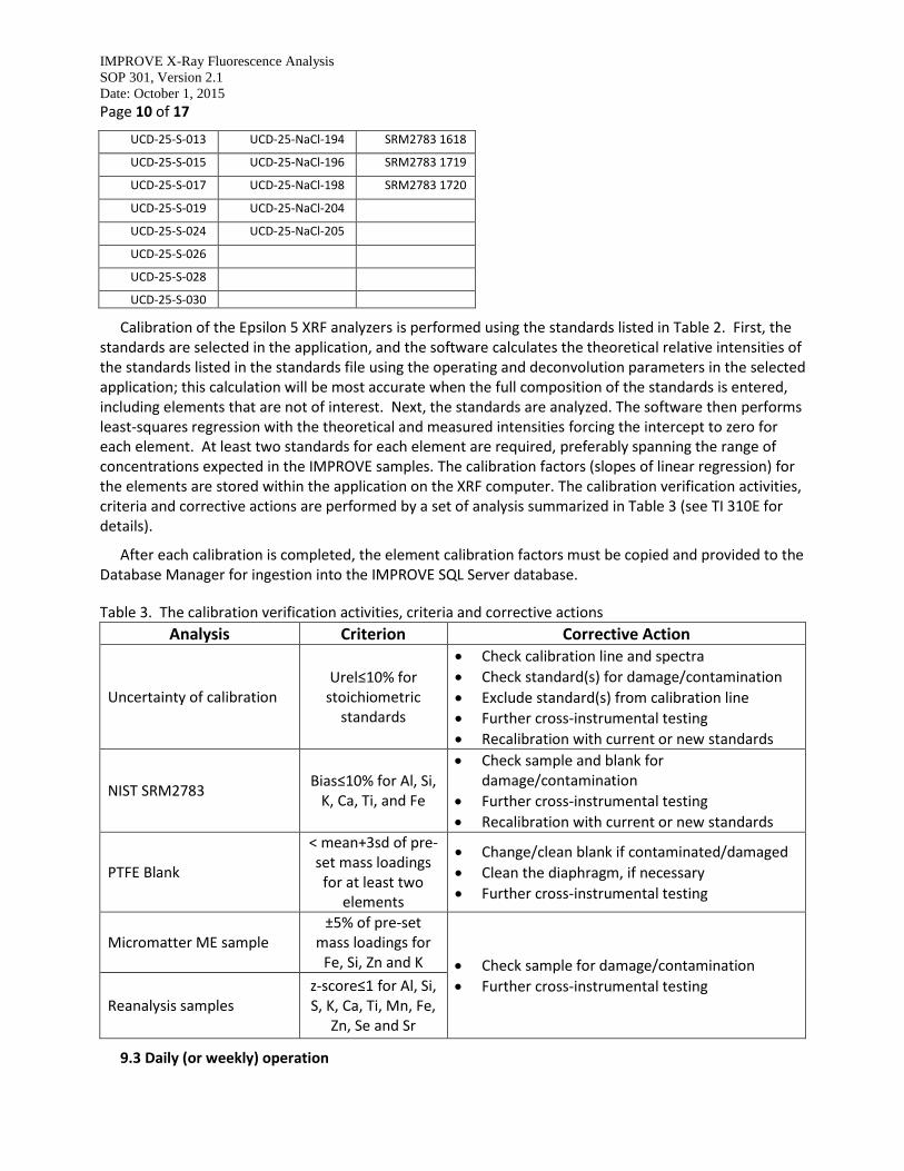
Calibration of the Epsilon 5 XRF analyzers is performed using the standards listed in Table 2. First, the standards are selected in the application, and the software calculates the theoretical relative intensities of the standards listed in the standards file using the operating and deconvolution parameters in the selected application; this calculation will be most accurate when the full composition of the standards is entered, including elements that are not of interest. Next, the standards are analyzed. The software then performs least-squares regression with the theoretical and measured intensities forcing the intercept to zero for each element. At least two standards for each element are required, preferably spanning the range of concentrations expected in the IMPROVE samples. The calibration factors (slopes of linear regression) for the elements are stored within the application on the XRF computer. The calibration verification activities, criteria and corrective actions are performed by a set of analysis summarized in Table 3 (see TI 310E for details).
After each calibration is completed, the element calibration factors must be copied and provided to the Database Manager for ingestion into the IMPROVE SQL Server database.
Table 3. The calibration verification activities, criteria and corrective actions
Analysis Criterion Corrective Action
Uncertainty of calibration Urel≤10% for
stoichiometric standards
Check calibration line and spectra
Check standard(s) for damage/contamination
Exclude standard(s) from calibration line
Further cross-instrumental testing
Recalibration with current or new standards
NIST SRM2783 Bias≤10% for Al, Si,
K, Ca, Ti, and Fe
Check sample and blank for damage/contamination
Further cross-instrumental testing
Recalibration with current or new standards
PTFE Blank
< mean+3sd of pre-set mass loadings
for at least two elements
Change/clean blank if contaminated/damaged
Clean the diaphragm, if necessary
Further cross-instrumental testing
Micromatter ME sample ±5% of pre-set
mass loadings for Fe, Si, Zn and K Check sample for damage/contamination
Further cross-instrumental testing Reanalysis samples
z-score≤1 for Al, Si, S, K, Ca, Ti, Mn, Fe,
Zn, Se and Sr
9.3 Daily (or weekly) operation

IMPROVE X-Ray Fluorescence Analysis
SOP 301, Version 2.1
Date: October 1, 2015
Page 11 of 17
Verify that analyzer is set for the current IMPROVE application (7 targets)
The current version of the IMPROVE application is used for analysis of all IMPROVE samples. The IMPROVE applications all use the same analytical settings. The processing parameters calibration factors are analyzer and time specific. Therefore, the application version number changes on an analyzer each time an element calibration is performed. The application performs fully automated analyses of samples under the specified conditions, saves the measured spectra within the application database, and processes the spectra into raw intensities. Spectra can be accessed and viewed while analysis is in progress.
Liquid nitrogen (LN2) fills
The Ge X-ray detector employed in the Epsilon 5 needs to be cooled with liquid nitrogen (LN2) to provide stability. It is necessary to regularly fill the dewar of about 20 L capacity with LN2. The LN2 is refilled every Wednesday. The software will prompt the user to refill the LN2 if it is running low, but under normal operating conditions, the LN2 should never run low if it is filled every week. The liquid nitrogen level calibration is performed automatically immediately following the refill, and the detector calibration is performed two hours later.
Users should refer to the System Users Guide and TI 301A for detailed safety information regarding the handling of liquid nitrogen and for specific instructions on performing the refill.
Detector calibration
The detector calibration process consists of repeated measurements of the Tungsten permanently installed in the Epsilon 5. Tungsten has a characteristic fluorescence for Kα at 58.856 keV and Lα at 8.396 keV, which are used to calibrate the corresponding energy channels. During the process, the photon signals coming from the detector to the DSP (Digital Signal Processor) are positioned into the appropriate energy channels. The calibration is typically performed on a weekly basis, following the weekly liquid nitrogen fill on Wednesdays. The analysis needs to be stopped to perform detector calibration. For more information on this process, please see TI 301A.
Creating and loading tray files
Tray files are a set of procedures written in .XML format that are used to queue samples. Tray files uniquely identify each sample by site and date. Thus, they record and track the sample associated with each collected spectrum. They also guide the laboratory technician in loading samples into the analyzer so that each sample is placed in its assigned position in the analysis queue. The procedures for creating, transferring, and using tray files are described in detail in TI 301B.
9.4 Loading and removing filters
Filter Handling
Sampled PTFE “A” filters previously received from the field are validated, post-weighed in the Sample Handling Laboratory, stored in Petri dishes, and organized according to a generated inventory list. For more information on these procedures, please see SOP 251, “Sample Handling.”
Filter Preparation
All IMPROVE “A” filters and “A” field blanks with valid status flags are organized into trays to be analyzed by XRF. More information on this process can be found in TI 251M, “AD Tray Check.”

IMPROVE X-Ray Fluorescence Analysis
SOP 301, Version 2.1
Date: October 1, 2015
Page 12 of 17
Sets of filters (8 traysx50 filters=400 filters per set) are assigned to the Epsilon 5 analyzers in a way that allows an equal distribution of field blanks among the analyzers. Epsilon 5 specific XRF tray files are created to organize and control distribution of the samples to each Epsilon 5 analyzer.
The specific procedures used for loading samples vary depending on whether 8 or 21 position trays are being used. In general, tray files are transferred to the PANalytical sample changer software using a program called LIMS. Filters are transferred from labeled Petri dishes to the tray and position designated by the tray file. Once a tray has been loaded and placed in the analyzer, the samples are queued using the software. Detailed instructions for loading and unloading the trays can be found in TI 301C.
At this time, filters are only identified by the position of the cup they have been placed in once the filters have been removed from their labeled Petri dishes. Special attention must be given during loading and unloading to assure the proper identity of samples. In addition, any physical changes to the sample after analysis (torn, dropped, etc.) must be reported and noted in the database.
10. DATA AND RECORDS MANAGEMENT
10.1 Log books
Each day the IDs (site and date) of the first and last samples loaded into each XRF analyzer are logged into the respective XRF Analyzer log book. The detailed list of all samples analyzed is included in that day’s trayfiles, which serve as an electronic version of the log book.
10.2 Transferring data to the IMPROVE database
The Epsilon 5 software calculates raw intensities and stores them in a results database table within the application in which the samples were analyzed. At a designated time interval (usually nightly) a program referred to as the XRF Migration Service uploads any new raw intensities data to a table in the IMPROVE database.
10.3 Data storage and backups
Raw and processed spectra are saved and available for use at any time on the Epsilon 5 computers. Copies of the intensity data are stored in the IMPROVE SQL Server database. Small changes or corrections are sometimes made to the sample metadata (e.g., sample dates may be swapped) during the data validation process. The details of data validation process can be found in TI 301D. These changes are recorded in a “Table of Changes” in the IMPROVE SQL Server database.
A backup service copies the files from each Epsilon 5 PC and places them in analyzer-specific compressed folders on CNL’s backup server. Differential backups are performed daily, while full backups are performed weekly.
10.4 Calculation of mass loadings, Minimum Detectable Limits (MDLs), and uncertainties
Several different stored procedures in the IMPROVE SQL Server database are executed to calculate median field blank (FB) intensities, blank-correct the raw sample intensities, calculate mass loadings for each of the elements detected in the sample, and calculate uncertainties and minimum detectable limits. The stored procedures are described in detail in TI 301D.
Blank correction is applied to each set of XRF data during data processing. Blank correction is specific to an analyzer, an analyzer application, and a month. The blank correction procedure consists of the following steps:

IMPROVE X-Ray Fluorescence Analysis
SOP 301, Version 2.1
Date: October 1, 2015
Page 13 of 17
For each element, determine the median FB raw intensities for the sample month and each analyzer-configuration used with that month. The median FB raw intensities will be used to subtract from raw intensities of samples.
o For each analyzer select the last 25 FB results. o The 25 selected FBs for each analyzer that were used to calculate the blank subtraction
will be recorded in another table along with a new field to identify which month they were used to process, BlankSetID.
o Determine the median FB intensity (cps/mA) by element by sorting the intensities from high to low and select the 13th record.
o Save the median FB intensity (cps/mA) to another table along with the month for which they were calculated, the date on which they were calculated, and the BlankSetID parameter (described above).
Subtract the median FB intensity (cps/mA) from the sample intensity (cps/mA) to determine the blank-corrected intensity for each element in the selected month by analyzer and analyzer configuration.
Multiply the blank-corrected intensity for each element by the analyzer-configuration-specific calibration factor for that element. This converts the blank-corrected intensities to blank-corrected mass/area (µg/cm2) loadings that will be exported into a .dbf file for subsequent processing and final delivery.
Minimum detectable limits (MDLs) for XRF have been determined separately for each of the three Epsilon 5 analyzers used for IMPROVE. The MDLs were determined from the analysis of approximately 50 to 100 field blanks on each analyzer, performed in 2012. For each element on each analyzer the MDL was calculated as the 95th percentile value of the intensity measured on these field blanks. The analyzer calibration factors in effect at that time were used to convert the intensities (cps/mA) to elemental mass loadings (µg/cm2). These MDLs are static, with the same value being used for all samples analyzed subsequently on each analyzer.
Uncertainties for each element are calculated by combining estimates of the additive and proportional uncertainties in the measurement. Additive uncertainties are derived from the MDLs described above. One-sigma additive uncertainty is estimated as MDL/1.6449, 1.6449 being the 95% critical value for a normal distribution. Coefficients for proportional uncertainties were based on the XRF analysis of paired samples from sites with collocated modules. For each pair in which both values A1 and A2 are above three times the MDL, the signed scaled relative difference was calculated as:
𝑅𝐷 = √2(𝐴 − 𝐵)
(𝐴 + 𝐵)
The one-sigma proportional uncertainty coefficient was then estimated as one-half the difference between the 84th and 16th percentiles of these RD values, equivalent to one standard deviation for a normal distribution. Data from collocated pairs analyzed on two of CNL’s Epsilon 5 analyzers were used together without distinction. Data for the third analyzer were treated separately. These proportional uncertainty coefficients are static, with the same value being used for all samples analyzed subsequently.
The one-sigma uncertainty, Ui, associated with each XRF measurement of element i (µg/cm2) is then determined as:
𝑈𝑖 = √(𝐴𝑑𝑑𝑖𝑡𝑖𝑣𝑒 𝑢𝑛𝑐𝑒𝑟𝑡𝑎𝑖𝑛𝑡𝑦𝑖)2 + (𝑝𝑟𝑜𝑝𝑜𝑟𝑡𝑖𝑜𝑛𝑎𝑙_𝑢𝑛𝑐𝑒𝑟𝑡𝑎𝑖𝑛𝑡𝑦_𝑐𝑜𝑒𝑓𝑓𝑖𝑐𝑖𝑒𝑛𝑡𝑖 ∗ 𝑚𝑎𝑠𝑠_𝑙𝑜𝑎𝑑𝑖𝑛𝑔𝑖)2
IMPROVE X-Ray Fluorescence Analysis
SOP 301, Version 2.1
Date: October 1, 2015
Page 14 of 17
where the mass loading is distinct for each field sample.
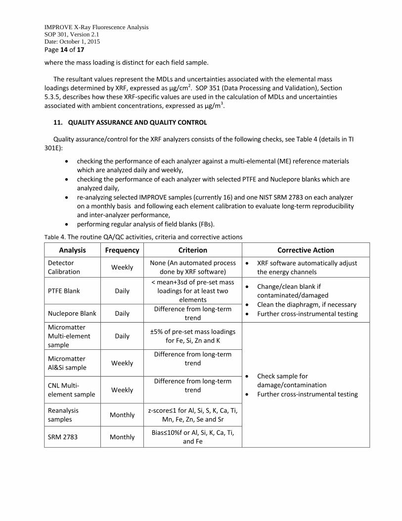
The resultant values represent the MDLs and uncertainties associated with the elemental mass loadings determined by XRF, expressed as µg/cm2. SOP 351 (Data Processing and Validation), Section 5.3.5, describes how these XRF-specific values are used in the calculation of MDLs and uncertainties associated with ambient concentrations, expressed as µg/m3.
11. QUALITY ASSURANCE AND QUALITY CONTROL
Quality assurance/control for the XRF analyzers consists of the following checks, see Table 4 (details in TI 301E):
checking the performance of each analyzer against a multi-elemental (ME) reference materials which are analyzed daily and weekly,
checking the performance of each analyzer with selected PTFE and Nuclepore blanks which are analyzed daily,
re-analyzing selected IMPROVE samples (currently 16) and one NIST SRM 2783 on each analyzer on a monthly basis and following each element calibration to evaluate long-term reproducibility and inter-analyzer performance,
performing regular analysis of field blanks (FBs).
Table 4. The routine QA/QC activities, criteria and corrective actions
Analysis Frequency Criterion Corrective Action
Detector Calibration
Weekly None (An automated process
done by XRF software) XRF software automatically adjust
the energy channels
PTFE Blank Daily < mean+3sd of pre-set mass
loadings for at least two elements
Change/clean blank if contaminated/damaged
Clean the diaphragm, if necessary
Further cross-instrumental testing Nuclepore Blank Daily Difference from long-term
trend
Micromatter Multi-element sample
Daily ±5% of pre-set mass loadings
for Fe, Si, Zn and K
Check sample for damage/contamination
Further cross-instrumental testing
Micromatter Al&Si sample
Weekly Difference from long-term
trend
CNL Multi-element sample
Weekly Difference from long-term
trend
Reanalysis samples
Monthly z-score≤1 for Al, Si, S, K, Ca, Ti,
Mn, Fe, Zn, Se and Sr
SRM 2783 Monthly Bias≤10%f or Al, Si, K, Ca, Ti,
and Fe
IMPROVE X-Ray Fluorescence Analysis
SOP 301, Version 2.1
Date: October 1, 2015
Page 15 of 17
11.1 Performance testing, control charts, tolerances and actions to be taken
The stability of the analyzers is monitored daily by analyzing multi-element (ME) Micromatter thin film reference materials containing Al, Si, Fe, K, Cl, Cs, Br, Zn and Te, PTFE and Nuclepore blanks. The results (mass loadings in μg/cm2 from each daily check) are recorded into a web application site. Graphs of the data are updated daily and can be viewed at any time.
The mass loadings of PTFE blanks should remain within the acceptance limits determined by the filter acceptance procedure as the mean ±3 standard deviations of the tested filters. If prolonged exceedance of the limits is observed, checks are made to determine possible causes (e.g., atmospheric deposition). PTFE blanks are air brushed to remove any possible contaminants. If the blank continues to exceed the limits, the filter is replaced with a new one. The mass loadings of the Nuclepore blank are monitored for anomalies in the system. Any unexpected increase or decrease in the mass loadings is investigated.
The mass loadings of ME reference samples must remain within a max 5% of bias from assigned values. The upper and lower acceptance limits (± 5%) and upper and lower warning limits (± 3%) of ME reference samples are listed and clearly marked on the charts (see Figure 2 below as an example). The upper/lower limits are based on the average raw intensities and elemental mass loadings from the first three analyses of the ME reference materials after the last calibration. If the values of each daily check are between the warning limits no action is necessary; if they are between the warning and acceptance limits, no immediate action is required but a few checks including another analyzing multi-element reference materials, calibration standards, etc. are performed to assure proper analytical settings. In addition, the ME reference material is air brushed to remove possible contaminants. In case of permanent damage, the ME reference material is replaced.
The Al&Si reference samples and CNL made ME sample are also routinely measured to check the instrumental performance. Any unexpected increase or decrease in the mass loadings is investigated.
The results of reanalysis samples must remain within pre-determined limits. The SRM 2783 biases for Al, Si, K, Ca, Ti, and Fe must remain equal to or less than 10%. If the results exceed the acceptance limits, several tests are performed to determine the cause and solve the problem.
The details of this testing can be found in TI 301E.
Successful outcome of the tests mentioned above grants further analysis of samples. If the values exceed acceptance limits, the XRF lab manager must be immediately notified and the problem must be fixed before analysis continues.

IMPROVE X-Ray Fluorescence Analysis
SOP 301, Version 2.1
Date: October 1, 2015
Page 16 of 17
Figure 2. Performance testing with ME reference material: daily monitoring of Fe mass loadings with warning (±3%, grey lines) and acceptance (±5%, out of scale) limits
11.2 Reproducibility testing
Long-term reproducibility is monitored by re-analyzing selected IMPROVE samples (currently 16) and 1 NIST SRM 2783 on each analyzer every month. The individual result of each monthly analysis is compared to its assigned reference value. The assigned reference value is determined as a mean of initial multiple time measurements. The difference between the result of each monthly analysis and its reference value is calculated and compared to their accompanying uncertainties. The average of this calculation for 17 samples must remain within their accompanying uncertainties. In other words, the average of absolute difference to uncertainty ratio must be lower than 1.
This process also serves as an inter-analyzer comparison check. The inter-analyzer long-term reproducibility of each Epsilon 5 analyzer is determined by comparing each monthly measurement to the average of the reference values from other two analyzers. If continuous exceedances of the limit are observed in reproducibility, the laboratory manager is notified and further tests are employed to determine the cause of the instability. The details of this testing can be found in TI 301E.
11.3 Data Validation
All data entries (e.g., sample ID, sample status, etc.) in the sample changer (from tray files) are verified to match actual samples loaded. If there are any discrepancies, notes are made and the laboratory manager is notified.
Data integrity, internal consistency and reasonableness of results are reviewed after analysis by the spectroscopist and/or laboratory manager.
The data integrity check consists of verifying that all valid samples were analyzed by XRF.
IMPROVE X-Ray Fluorescence Analysis
SOP 301, Version 2.1
Date: October 1, 2015
Page 17 of 17
Initial data validation to detect outliers/anomalies in the XRF data (so called Level I Validation of XRF data, see TI 301F for details) includes checking correlations between elements, ratios of sums of quantified elements to PM masses, ratios of crustal elements, and reconstructed elemental ratios provided from previous years’ measurements. The detected outliers/anomalies and basic statistics (e.g., mean, median and 90th percentile) for the examination of year to-year observed trends are reported for final validation. Any changes made to the original data are reflected in the “Table of Changes” and saved in the IMPROVE database. The details of this testing can be found in TI 301D.
11.4 Approval of data for final validation and delivery
After the initial data review is complete, the elemental composition data are merged with data from other analyses and undergo final validation before delivery.
12. REFERENCES
1. Panalytical Manual for Epsilon 5 2. B. Vekemans et.al. “Analysis of X-ray Spectra by Iterative Least Squares (AXIL): New Developments”.
1994, X-Ray Spectrometry, 23, 278-285.