important safety instructions save these …€¦ · important safety instructions save these...
TRANSCRIPT

1
INSTALLATION AND OPERATION MANUAL
1645 Lemonwood Dr.Santa Paula, CA. 93060, USA
Toll Free 1-888-262-3880Tel: 1-805-421-5114www.quickjack.com
IMPORTANT SAFETY INSTRUCTIONS SAVE THESE INSTRUCTIONS
PLEASE READ THE ENTIRE CONTENTS OF THIS MANUAL PRIOR TO INSTALLATION AND OPERATION. BY PROCEEDING WITH JACK INSTALLATION AND OPERATION YOU AGREE THAT YOU FULLY UNDERSTAND AND COMPREHEND THE FULL CONTENTS OF THIS MANUAL. FORWARD THIS MANUAL TO ALL OPERATORS. FAILURE TO OPERATE THIS EQUIPMENT AS DIRECTED MAY CAUSE INJURY OR DEATH.
MAN REV A 10-09-2015P/N 5900395
3,500 / 5,000 / 7,000 LB CAPACITY (1588 / 2268 / 3175 KG)QUICKJACK
MODELS:
BL-3500SLX VER C
BL-5000SLX VER C
BL-7000SLX VER C
BE SAFEYour new jack was designed and built with safety in mind. However, your overall safety can be increased with proper training and thoughtful operation on the part of the operator. DO NOT operate or repair this equipment without reading this manual and the important safety instructions shown inside. Keep this operation manual near the jack at all times. Make sure that ALL USERS read and understand this manual.
RECEIVINGThe shipment should be thoroughly inspected as soon as it is received. The signed Bill of Lading is acknowledgement by the shipping carrier as receipt of this product as listed in your invoice as being in a good condition of shipment. If any of these goods listed on this Bill of Lading are missing or damaged, do not accept goods until the shipping carrier makes a notation on the freight bill of the missing or dam-aged goods. Do this for your own protection.
QUICKJACK ™
By Ranger Products
WARNING!
PATENTED. ALL RIGHTS RESERVED
ORIGINAL INSTRUCTIONS IN ENGLISH LANGUAGE
Keep this operation manual near the machine at all times. Make sure that
ALL USERS read this manual.
2
This instruction manual has been prepared especially for you. Your new jack is the product of over 40 years of continuous research, testing and development;
it is the most technically advanced vehicle jack on the market today.
READ THIS ENTIRE MANUAL BEFORE INSTALLATION & OPERATION BEGINSThe manner in which you care for and maintain your QuickJack™ will have a direct effect on
its overall performance and longevity.
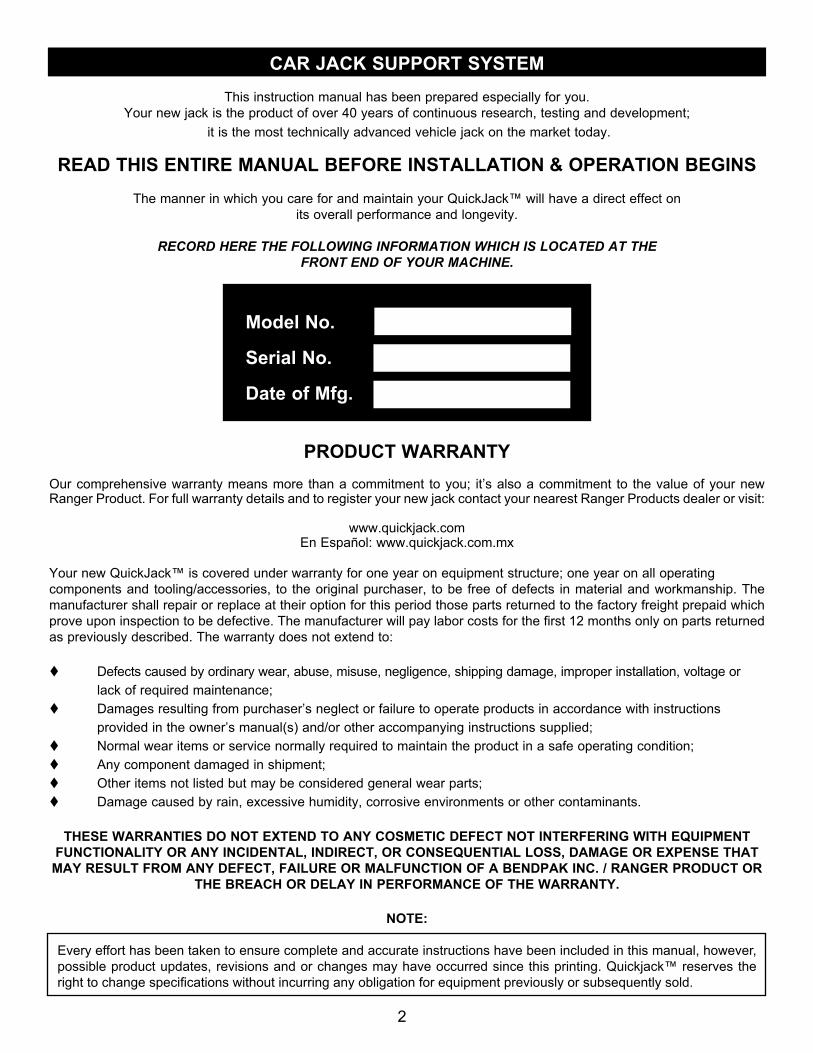
RECORD HERE THE FOLLOWING INFORMATION WHICH IS LOCATED AT THEFRONT END OF YOUR MACHINE.
PRODUCT WARRANTY Our comprehensive warranty means more than a commitment to you; it’s also a commitment to the value of your new Ranger Product. For full warranty details and to register your new jack contact your nearest Ranger Products dealer or visit:
www.quickjack.comEn Español: www.quickjack.com.mx
Your new QuickJack™ is covered under warranty for one year on equipment structure; one year on all operating components and tooling/accessories, to the original purchaser, to be free of defects in material and workmanship. The manufacturer shall repair or replace at their option for this period those parts returned to the factory freight prepaid which prove upon inspection to be defective. The manufacturer will pay labor costs for the first 12 months only on parts returned as previously described. The warranty does not extend to:
t Defects caused by ordinary wear, abuse, misuse, negligence, shipping damage, improper installation, voltage or lack of required maintenance;t Damages resulting from purchaser’s neglect or failure to operate products in accordance with instructions provided in the owner’s manual(s) and/or other accompanying instructions supplied;t Normal wear items or service normally required to maintain the product in a safe operating condition;t Any component damaged in shipment;t Other items not listed but may be considered general wear parts;t Damage caused by rain, excessive humidity, corrosive environments or other contaminants.
THESE WARRANTIES DO NOT EXTEND TO ANY COSMETIC DEFECT NOT INTERFERING WITH EQUIPMENT FUNCTIONALITY OR ANY INCIDENTAL, INDIRECT, OR CONSEQUENTIAL LOSS, DAMAGE OR EXPENSE THAT MAY RESULT FROM ANY DEFECT, FAILURE OR MALFUNCTION OF A BENDPAK INC. / RANGER PRODUCT OR
THE BREACH OR DELAY IN PERFORMANCE OF THE WARRANTY.
NOTE:
Every effort has been taken to ensure complete and accurate instructions have been included in this manual, however, possible product updates, revisions and or changes may have occurred since this printing. Quickjack™ reserves the right to change specifications without incurring any obligation for equipment previously or subsequently sold.
CAR JACK SUPPORT SYSTEM
Model No.
Serial No.
Date of Mfg.

3
Product Warranty . . . . . . . . . . . . . . . . . . . . . . . . . . . .. . .. . . . . . . . . . . . . . . . . . . . . . . . . . . . . . . . . . . . . . . . . . . . . . . . . . . . . 2 Definitions of Hazard Levels . . . . . . . . . . . . . . . . . . . . . . . . . . . . . . . . . . . . . . . . . . . . . . . . . . . . . . . . . . . . . . . . . . . . . . . . . . . 4
Important Safety Instructions . . . . . . . . . . . . . . . . . . . . . . . . . . . . . . . . . . . . . . . . . . . . . . . . . . . . . . . . . . . . . . . . . . . . . . . . . . . . . . . 5
Parts Inventory . . . . . . . . . . . . . . . . . . . . . . . . . . . . . . . . . . . . . . . . . . . . . . . . . . . . . . . . . . . .. . . . . . . . . . . . . . . . . . . . . . . . . . . 6 Specifications BL-3500SLX / BL-5000SLX/ BL-7000SLX. . . . . . . . . . . . . . . . . . . . . . . . . . . . . . . . . . . . . . . . . . . . . . . . . . . . . . .7
Tools Required / Getting Started . . . . . . . . . . . . . . . . . . . . . . . . . . . . . . . . . . . . . . . . . . . . . . . . . . . . . . . . . . . . . . . . . . . . . . . . . 8
Selecting Site / Floor Requirements / Unpacking . . . . . . . . . . . . . . . . . . . . . . . . . . . . . . . . . . . . . . . . . . . . . . . . . . . . . . . . . . . . . . . . . . . . . . . . . 8
Installing Cylinder Fittings . . . . . . . . . . . . . . . . . . . . . . . . . . . . . . . . . . . . . . . . . . . . . . . . . . . . . .. . . . . . . . . . . . . .. . . . . . . . . 8
Installing Cylinder Fittings (Cont’d) / Installing Inflation Valves . . . . . . . . . . . . . . . . . . . . . . . . . . . . . . . . . . . . . . . . . . . . . . . . . . . . . .9
Pressurizing Air Bottle Cylinders / Power Unit Assembly . . . . . . . . . . . . . . . . . . . . . . . . . . . . . . . . . . . . . . . . . . . . . . . . . . . . . .10
Power Unit Assembly (Cont’d) . . . . . . . . . . . . . . . . . . . . . . . . . . . . . . . . . . . . . . . . . . . . . . . . . . . . . . . . . . . . . . . . . . . . . . . . 11
Filling Power Unit Reservoir / Preparing Hoses . . . . . . . . . . . . . . . . . . . . . . . . . . . . . . . . . . . . . . . . . . . . . . . . . . . . . . .. . . . . .12
Preparing Hoses (Cont’d) . . . . . . . . . . . . . . . . . . . . . . . . . . . . . . . . . . . . . . . . . . . . . . . . . . . . . . . . . . . . . . . . . . . .. . . . . . . . . 13 . Jack Preparation. . . . . . . . . . . . . . . . . . . . . . . . . . . . . . . . . . . . . . . . . . . . . . . . . . . . . . . . . . . . . . . . . . . . . . . . . . . . . . . . 14 - 15
Bleeding the Cylinders . . . . . . . . . . . . . . . . . . . . . . . . . . . . . . . . . . . . . . . . . . . . . . . . . . . . . . . . . . . . . . . . . . . . . . . . . . . . . .15 - 16
Operation and Use . . . . . . . . . . . . . . . . . . . . . . . . . . . . . . . . . . . . . . . . . . . . . . . . . . . . . . . .. . . . . . . . . . . . . . . . . . . . . . . .16 - 17
Typical Jacking Points / Proper and Improper Set - Up. . . . . . . . .. . . . . . . . .. . . . . . . . . . . . . . . . . . . . . . . . . . . . . . . . . . . . .17 -18
Important Hydraulic Power Start-Up Instructions . . . . . . . . . . . . . . . . . . . .. . . . . . . . . . . . .. . . . . . . . . . . . . . . . . . . . .. . . . . . . . 18
To Raise Jack Frames . . . . . . . . . . . . . . . . . . . . . . . . . . . . . . . . . . . . . . . . . . . . . . . . . . . . . . . . . . . . . . . . . . . . . . . . . . . . . . .19
Lowering Jack - Parked on Low Lock / Parked on Upper Lock . . . . . . . . . . . . . . . . . . . . . . . . . . . . . . . . . . . . . . . . . . . . . . . . 20
Important Operating / Maintenance Instructions . . . . . . . . . . . . . . . . . . . . . . . . . . . . . . . . . . . . . . . . . . . . . . . . . . . . . . . . . .21 - 22
Lubrication Points . . . . . . . . . . . . . . . . . . . . . . . . . . . . . . . . . . . . . . . . . . . . . . . . . . . . . . . . . . . . . . . . . . . . . . . . . . . . . . . . . . . 23
Troubleshooting Instructions . . . . . . . . . . . . . . . . . . . . . . . . . . . . . . . . . . . . . . . . . . . . . . . . . . . . . . . . . . . . . . . . . . . . . . . . . . 24
SUV and Light Truck Adapter Kit . . . . . . . . . . . . . . . . . . . . . . . . . . . . . . . . . . . . . . . . . . . . . . . . . . . . . . . . . . . . . . . . . . . . . . . 25 Labels and Label Positioning . . . . . . . . . . . . . . . . . . . . . . . . . . . . . . . . . . . . . . . . . . . . . . . . . . . . . . . . . . . . . . . . . . . .. . . . . . 26 - 27
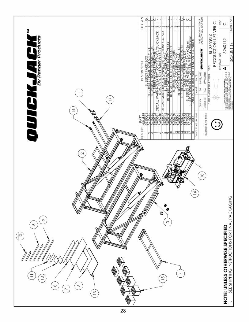
Parts Breakdowns . . . . . . . . . . . . . . . . . . . . . . . . . . . . . . . . . . . . . . . . . . . . . . . . . . . . . . . . . . . . . . . . . . . . . . . . . . . . .. . . 28 - 38 Declaration of Conformity . . . . . . . . . . . . . . . . . . . . . . . . . . . . . . . . . . . . . . . . . . . . . . . . . . . . . . . . . . . . . . . . . . . . . . . . . . . . . . 39
TABLE OF CONTENTS
4
Stay clear of any moving parts that can fall and cause injury. These instructions must be followed to insure proper instal-lation and operation of your jack. Failure to comply with these instructions can result in serious bodily harm and void product warranty. Manufacturer will assume no liability for loss or damage of any kind, expressed or implied resulting from improper installation or use of this product.
DEFINITIONS OF HAZARD LEVELS
Identify the hazard levels used in this manual with the following definitions and signal words:
Watch for this symbol as it means: Immediate hazards which will result in severe personal injury or death.
Watch for this symbol as it means: Hazards or unsafe practices which could result in severe personal
injury or death.
Watch for this symbol as it means: Hazards or unsafe practices which may result in minor personal injury,
product or property damage.
OWNER’S RESPONSIBILITY
To maintain the jack and user safety, the responsibility of the owner is to read and understand these instructions:
t Follow all installation and operation instructions.t Make sure installation conforms to all applicable Local Regulations and Electrical Codes.t Carefully check the product for correct initial function.t Read and follow the safety instructions. Keep them readily available for machine operators.t Make certain all operators are properly trained, know how to safely and correctly operate the unit, and are properly supervised.
t Allow unit operation only with all parts in place and operating safely.t Carefully inspect the unit on a regular basis and perform all maintenance as required.t Service and maintain the unit only with authorized or approved replacement parts.t Keep all instructions permanently with the unit and all decals on the unit clean and visible.
INSTALLER / OPERATORPLEASE READ AND FULLY
UNDERSTAND. BY PROCEEDING YOU AGREE TO THE FOLLOWING:
t I have visually inspected the site where the jack is tobe installed and verified the concrete to be in good condition and free of cracks or other defects. I understand that installing a jack on cracked or defective concrete couldcause jack failure resulting in personal injury or death. t I understand that a level floor is required for properinstallation and level lifting.t I understand that I am responsible if my floor is ofquestionable slope and that I will be responsible for allcharges related to pouring a new level concrete slab ifrequired and any charges.t I will assume full responsibility for the concrete floorand condition thereof, now or later, where the aboveequipment model is to be installed. Failure to followDanger, Warning, and Caution instructions may lead toserious personal injury or death to operator or bystanderor damage to property.
BEFORE YOU BEGIN RECEIVING YOUR SHIPMENT
The shipment should be thoroughly inspected as soon as itis received. The signed bill of lading is acknowledgement bythe carrier of receipt in good condition of shipment coveredby your invoice. If any of the goods called for on the bill oflading are shorted or damaged, do not accept them until thecarrier makes a notation on the freight bill of the shorted ordamaged goods. NOTIFY THE CARRIER AT ONCE if any hidden loss or damage is discovered after receipt and request the carrier to make an inspection.
IT IS DIFFICULT TO COLLECT FOR LOSS OR DAMAGE AFTER YOU HAVE GIVEN THE CARRIER A CLEAR RECEIPT. File your claim with the carrier promptly. Support your claim with copies of the bill of lading, freight bill, invoice, and photographs, if available.
IMPORTANT NOTICE

5
IMPORTANT SAFETY INSTRUCTIONSRead these safety instructions entirely. Do not attempt to install this QuickJack if you have never been trained
on basic vehicle jack installation procedures. Never attempt to lift components without proper lifting tools such as forklifts or cranes. Stay clear of any moving parts that may fall and cause injury. When using your garage equipment,
basic safety precautions should always be followed, including the following:
1. Read and understand all instructions and all safety warnings before operating jack.
2. Care must be taken as burns can occur from touching hot parts.
3. DO NOT operate equipment with a damaged electrical cable or hydraulic hose or if the equipment has been dropped or damaged until it has been examined by a qualified service person.
4. DO NOT let an electrical cord hang over the edge of the table, bench, or counter or come in contact with hot manifolds or moving fan blades.
5. Care should be taken to arrange the electrical cord and hydraulic hose so that it will not be tripped over or pulled.
6. Adequate ventilation should be provided when working on operating internal combustion engines.
7. Keep hair, loose clothing, fingers, and all parts of body away from moving parts. Keep feet clear of jack when lowering. Avoid pinch points.
8. Use only as described in this operation manual. Use only manufacturer’s recommended attachments.
9. ALWAYS USE FOOTWEAR AND SAFETY GLASSES. Everyday eyeglasses only have impact resistant lenses, they are not safety glasses.
10. Consider work environment. Keep work area clean. Cluttered work areas invite injuries. Keep areas well lit.
11. Only trained operators should operate this jack. All non-trained personnel should be kept away from the work area. Never let non-trained personnel come in contact with, or operate jack.
12. Clear area if vehicle is in danger of falling.
13. ALWAYS make sure the safeties are engaged before attempting to work on or near a vehicle.
14. MAINTAIN WITH CARE. Keep jack clean for better and safer performance. Follow manual for proper lubrication and maintenance instructions. Keep control handles and/or buttons dry, clean and free from grease and oil.
15. Check for damaged parts. Check for alignment of moving parts, breakage of parts or any condition that may affect operation of jack. Do not use jack if any component is broken or damaged.
16. NEVER remove safety related components from the jack. Do not use jack if safety related components are missing or damaged.
17. STAY ALERT. Use common sense and watch what you are doing. Remember, SAFETY FIRST.
SAVE THESE INSTRUCTIONS IN AN ACCESSIBLE LOCATION
IMPORTANTSAFETY INSTRUCTIONSQUICKJACK ™
By Ranger Products

6
SLX MODELS PARTS INVENTORYBe sure to take a complete inventory of parts prior to beginning installation.
DESCRIPTION QTYFrame Assemblies 2Power Unit with Carrier 1Quick Connect Twin Hose Assembly 1Quick Connect Hoses 2Rubber Lift Blocks 8Frame Handles 2Parts Box (Packing List Enclosed) 1
FrameAssemblies Power Unit with
Carrier
Twin Hose Assembly
Short Leader Hoses
Rubber Lift Blocks
Quick Frame Handles
*The design, material and specifications are subject to change without notice.

7
SLX MODELS SPECIFICATIONS
MODEL
BL‐350
0SLX
BL‐500
0SLX
BL‐700
0SLX
Lifting capacity per pair
3,50
0 lbs. / 1588
kg.
5,00
0 lbs. / 2268
kg.
7,00
0 lbs. / 3175
kg.
(A) M
inim
um collapsed
height
3” / 76
mm.
3” / 76
mm.
3.5” / 89
mm.
(B) P
latform lifting he
ight (Frame on
ly)
16.5” / 4
19 m
m.
17.2” / 4
37 m
m.
17.7” / 4
50 m
m.
(C) P
latform lifting he
ight (w
ith sm
all rub
ber b
lock)
17” / 4
32 m
m.
17.8” / 4
52 m
m.
18.2” / 4
62 m
m.
(D) P
latform lifting he
ight (w
ith ta
ll rubb
er block)
18.5” / 4
70 m
m.
19” / 4
83 m
m.
19.2” / 4
88 m
m.
(E) P
latform lifting he
ight (w
ith stacked rubb
er blocks)
20” / 5
08 m
m.
22.5” / 5
72 m
m.
21.2” / 5
38 m
m.
(F) Frame width
10.55” / 268 mm.
11” / 2
78 m
m.
12.5” / 3
18 m
m.
(G) R
ubbe
r lift block position
‐ max. spread
50.5” / 1
283 mm.
60” / 1
524 mm.
60” / 1
524 mm.
(H) R
ubbe
r lift block position
‐ min. spread
26.7” / 6
78 m
m.
31.5” / 8
00 m
m.
31.5” / 8
00 m
m.
(I) Overall fram
e length
62” / 1
575 mm.
72.5” / 1
841 mm.
72.5” / 1
841 mm.
Individu
al jack fram
e ‐ n
et weight (ea.)
60 lbs. / 27
kg.
76 lbs. / 34
kg.
91 lbs. / 41
kg.
Power unit/carrier com
plete ‐ n
et weight
35 lbs. / 16
kg.
35 lbs. / 16
kg.
35 lbs. / 16
kg.
Gross weight
180
212
242
Noise emission
<45d
BA<45d
BA<45d
BA
QU
ICK
JA
CK
™
By R
an
ge
r P
rod
uc
ts

8
STEP 1Selecting Site
Before installing your new jack, check the following:
1. JACK LOCATION: Always make sure that adequate space is available for installation. Your new QuickJack is shipped in two boxes. Approximate dimensions are shownbelow.
2. OVERHEAD OBSTRUCTIONS: The area where the jack will be located should be free of any overhead obstructions such as heaters, building supports, electrical lines etc.
3. DEFECTIVE FLOOR: Visually inspect the site where the jack is to be installed and check for defective concrete or asphalt.
STEP 2Floor Requirements
DO NOT POSITION JACK FRAMES IN THE PATH OF A VEHICLE OR DRIVE OVER JACK FRAMES. PERSONAL INJURY, PRODUCT OR PROPERTY
DAMAGE MAY RESULT.
This jack must be installed on a solid level area with no more than 3° of slope. Failure to do so could cause personal injury or death.
STEP 3Unpacking
1. After choosing the area of installation, open packaging and remove the frames, handles, hoses and power unit.
2. Place the QuickJack frames near work area.
STEP 4Installing Cylinder Fittings
1. Remove the shipping plugs from the hydraulic cylinders as shown below.
t Open-End Wrench Set: SAE/Metrict Socket And Ratchet Set: SAE/Metric
t Phillips Screwdrivert Wrench sizes: 7/16”, 3/8”, 5/8”, 11/16” and 3/4”
IMPORTANT NOTICETHESE INSTRUCTIONS MUST BE FOLLOWED TO ENSURE PROPER INSTALLATION AND OPERATION OF YOUR JACK. FAILURE TO COMPLY WITH THESE INSTRUCTIONS CAN RESULT IN SERIOUS BODILY HARM AND VOID PRODUCT WARRANTY. MANUFACTURER WILL ASSUME NO LIABILITY FOR LOSS OR DAMAGE OF ANY KIND,
EXPRESSED OR IMPLIED, RESULTING FROM IMPROPER INSTALLATION OR USE OF THIS PRODUCT.PLEASE READ ENTIRE MANUAL PRIOR TO INSTALLATION
TOOLS REQUIRED
FLOOR MUST BE DRY, FLAT, LEVEL AND COMPACT AND HAVE A MINIMUM COMPRESSIVE STRENGTH
OF 500 PSI. A LEVEL FLOOR IS REQUIRED FOR PROPER INSTALLATION AND LEVEL LIFTING.

9
2. Install the 90º O-ring fittings and position the fittings at 10 o’clock.
3. Using a wrench, secure the fitting nut.
STEP 5Installing Inflation Valves
Appropriate procedures must be employed for effective assembly of the air inflation valve located on each air bottle cylinder. Installation torque and cleanliness should be addressed when installing.
1. Using a hex key wrench, remove shipping plugs from both air bottle cylinders.
2. Wrap the threads on the two air inflation valves with Teflon™ tape. When applying tape, wrap it three times in
a clockwise rotation, as shown below. (Fig. 1) WARNING: Never allow Teflon tape to pass over end of threads or system contamination will occur. (Fig. 2)
3. Carefully thread each air inflation valve into each air bottle cylinder as shown. NOTE: It is strongly recommended that air infaltion valves be started by hand to minimize cross-threading.
4. Gently tighten each inflation valve.
EXCESS PACKING OIL MAY RELEASE FROM THE AIR BOTTLE CYLINDER. AVOID CONTACT WITH
HYDRAULIC FLUIDS. USE PERSONAL PROTECTIVE EQUIPMENT. IF HYDRAULIC FLUID COMES IN
CONTACT WITH EYES, GETS INTO THE BLOODSTREAM OR IS SWALLOWED, PLEASE
CONSULT A DOCTOR IMMEDIATELY.
This will cause system contamination.
Fig. 1
Fig. 2
10
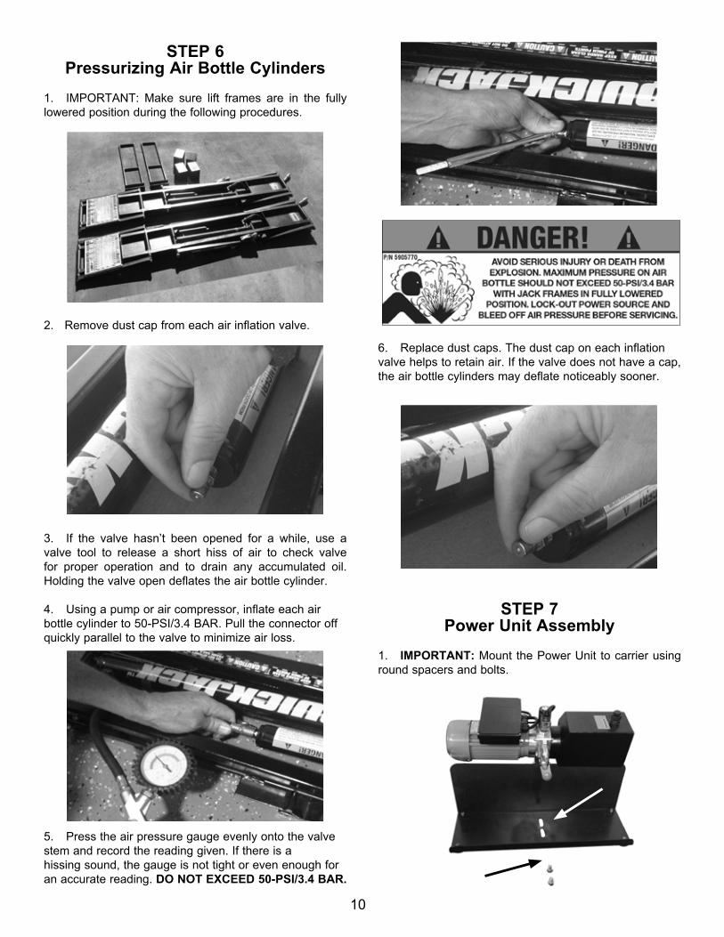
STEP 6Pressurizing Air Bottle Cylinders
1. IMPORTANT: Make sure lift frames are in the fully lowered position during the following procedures.
2. Remove dust cap from each air inflation valve.
3. If the valve hasn’t been opened for a while, use a valve tool to release a short hiss of air to check valve for proper operation and to drain any accumulated oil. Holding the valve open deflates the air bottle cylinder.
4. Using a pump or air compressor, inflate each air bottle cylinder to 50-PSI/3.4 BAR. Pull the connector off quickly parallel to the valve to minimize air loss.
5. Press the air pressure gauge evenly onto the valve stem and record the reading given. If there is a hissing sound, the gauge is not tight or even enough for an accurate reading. DO NOT EXCEED 50-PSI/3.4 BAR.
6. Replace dust caps. The dust cap on each inflation valve helps to retain air. If the valve does not have a cap, the air bottle cylinders may deflate noticeably sooner.
STEP 7 Power Unit Assembly
1. IMPORTANT: Mount the Power Unit to carrier using round spacers and bolts.

11
2. Remove protective shipping plugs from both power unit ports.
3. Locate both double-male O-ring fittings, then wrap Teflon tape on pipe threads only - NOT O-RING SIDE.
4. Place one double-male O-ring fitting in the lower port, with the O-ring facing inward.
5. Securely tighten fitting.
6. Install male quick-connect fitting to lower double-male fitting.
7. Securely tighten fitting.
8. Repeat same steps for the upper port. Both fittings should be installed as shown in the images below.
TING COMPONENTS AND CHECK FOR PROPER

12
STEP 8 Filling Power Unit Reservoir
1. Remove complete oil reservoir fill cap and screw nut assembly using an adjustable wrench.
2. Remove cap and place in a non-contaminated area.
3. Fill the reservoir with approximately 2 quarts/1.9 litres of automatic transmission fluid. (Use Dextron III ATF or similar grade) Make sure the funnel used to fill the power unit oil reservoir is clean.
4. Replace oil fill cap assembly and tighten firmly.
STEP 9Preparing Hoses
READ THE FOLLOWING PROCEDURES BEFORE ATTEMPTING TO CONNECT HOSES TO QUICKJACK
AND POWER UNIT.
1. Remove protective caps from threaded fittings on both ends of Twin Hose Assembly.
2. Wrap the threads with Teflon tape. When applying tape, wrap it three times in direction shown below.
3. Install female quick-connect fitting onto threaded end.
DURING THE START-UP PROCEDURE OBSERVE ALL OPERATING COMPONENTS AND CHECK FOR
PROPER INSTALLATION AND ADJUSTMENT. DO NOT ATTEMPT TO RAISE A LOAD UNTIL A THORUGH OP-
ERATIONAL CHECK HAS BEEN COMPLETED.

13
4. Securely tighten female fitting as shown below.
5. Repeat same procedure for ALL four hose ends, as shown in the image below.
6. Locate both Short Leader Hoses and remove protective caps from threaded fittings.
7. Wrap threaded ends with Teflon tape at least three times. Tape should be wrapped in direction shown below.
8. Locate the two remaining male quick-connect fittings and attach to Short Leader Hoses as shown below.
9. Connect both Short Leader Hoses to each hydraulic cylinder.
10. Route Short Leader Hoses under frame ends making sure they are clear from any pinch points.

14
STEP 10Jack Preparation
1. Place both QuickJack frames on a stable floor surface with both lock bars positioned outwards as illustrated below.
2. Check for proper tension on the safety lock bar retaining nuts. The safety lock bar must swing freely.
3. Remove any dirt, scales, chips or any foreign debris from your quick-connect fittings to avoid contamination or malfunction of the equipment.
4. TO CONNECT: Install the male fitting into the female fitting. Full connection is made when the ball release sleeve slides forward on the female fitting.TO DISCONNECT: Hold the male fitting then retract the sleeve on the female fitting until the fittings disconnect.
5. For DC Power Units connect directly to a 12-volt power source. Minimum requirement for jumper cables in the USA should be: 7 Gauge. For European countries:10 square millimeters.
6. For DC Power Units connect the 12-volt negative source to the negative terminal and the 12-volt positive power source to the positive terminal. See below images or follow instructions accompanying the unit.
VISUALLY CHECK QUICK-CONNECT FITTINGS FOR CORRODING, CRACKING, DAMAGE OR EXCESSIVE WEAR. IF ANY OF THESE
CONDITIONS EXIST, THE QUICK-CONNECT FITTINGS MUST BE REPLACED.

15
7. Make sure the power unit oil reservoir is full with 2 quarts/1.9 litres of automatic transmission fluid. (Use Dextron III ATF or similar grade.) The fluid level should be approximately 1/2” (12mm) below the fill hole.
8. Check air pressure in the air bottle cylinders. Make sure both register 50-PSI. DO NOT EXCEED 50-PSI/3.4 BAR.
10. Test the Power Unit by pressing the UP button. If the motor sounds like it is operating properly, raise jacks half way and check all hose connections for leaks. If the motor gets hot or sounds irregular, stop and check all electrical connections.
11. Cycle the jack up and down a few times to approximately half the lifting height, ensuring proper operation.
12. Engage safety bars by raising past safety lock then lower jack onto safeties by depressing the DOWN button. Check both safety lock bars for proper operation before proceeding.
STEP 11Bleeding the Cylinders
Raise QuickJack approximately half lifting height and then follow these procedures to drain and bleed cylinders.
1. BLEEDING AIR FROM HYDRAULIC SYSTEM. • Slightly loosen bleeder screw on the back side of the hydraulic cylinder using a hexagon wrench. WARNING: Keeps hands clear of pinch points.
• Slowly charge the hydraulic cylinders with oil by briefly pressing the UP button on the power unit pendant control. Air and oil will start to exit. • When you observe oil exiting the cylinder without bubbles, the air has been removed. • Tighten the hex socket bleed screw using a hexagon wrench to close and create a tight seal. DO NOT OVERTIGHTEN.
2. REMOVING PACKING OIL FROM AIR CHARGE CYLINDERS. • Using a pump or air compressor, inflate each air bottle cylinder to 50-PSI/3.4 BAR. • Use a valve tool or blunt-nose tool to depress the
16
valve core plunger to release any accumulated packing oil from the air charge cylinders. See image below.
• Repeat steps until air charge cylinders are completely drained of packing oil. • Place contaminated materials in disposable containers and dispose of in a manner consistent with applicable regulations.
STEP 12Operation and Use
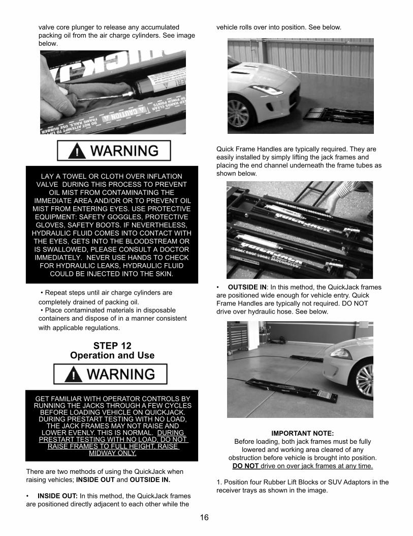
There are two methods of using the QuickJack when raising vehicles; INSIDE OUT and OUTSIDE IN.
• INSIDE OUT: In this method, the QuickJack frames are positioned directly adjacent to each other while the
vehicle rolls over into position. See below.
Quick Frame Handles are typically required. They are easily installed by simply lifting the jack frames and placing the end channel underneath the frame tubes as shown below.
• OUTSIDE IN: In this method, the QuickJack frames are positioned wide enough for vehicle entry. Quick Frame Handles are typically not required. DO NOT drive over hydraulic hose. See below.
IMPORTANT NOTE: Before loading, both jack frames must be fully
lowered and working area cleared of any obstruction before vehicle is brought into position.
DO NOT drive on over jack frames at any time.
1. Position four Rubber Lift Blocks or SUV Adaptors in the receiver trays as shown in the image.
GET FAMILIAR WITH OPERATOR CONTROLS BY RUNNING THE JACKS THROUGH A FEW CYCLES
BEFORE LOADING VEHICLE ON QUICKJACK. DURING PRESTART TESTING WITH NO LOAD,
THE JACK FRAMES MAY NOT RAISE AND LOWER EVENLY. THIS IS NORMAL. DURING
PRESTART TESTING WITH NO LOAD, DO NOT RAISE FRAMES TO FULL HEIGHT, RAISE
MIDWAY ONLY.
LAY A TOWEL OR CLOTH OVER INFLATION VALVE DURING THIS PROCESS TO PREVENT
OIL MIST FROM CONTAMINATING THE IMMEDIATE AREA AND/OR OR TO PREVENT OIL MIST FROM ENTERING EYES. USE PROTECTIVE EQUIPMENT: SAFETY GOGGLES, PROTECTIVE GLOVES, SAFETY BOOTS. IF NEVERTHELESS,
HYDRAULIC FLUID COMES INTO CONTACT WITH THE EYES, GETS INTO THE BLOODSTREAM OR IS SWALLOWED, PLEASE CONSULT A DOCTOR IMMEDIATELY. NEVER USE HANDS TO CHECK
FOR HYDRAULIC LEAKS, HYDRAULIC FLUID COULD BE INJECTED INTO THE SKIN.

17
IMPORTANT NOTE: Do not attempt to lift any load on the upper frame rail. Use
Rubber Lift Blocks only. Rubber Lift Blocks or SUV Adaptors must only be placed in the receiver trays.
2. With vehicle in ready position, place each jack frame under the vehicle making sure to position the Rubber Lift Blocks at the factory recommended jacking points. Ensure vehicle is positioned with the center-of-balance placed midway on the jack frames.
TYPICAL JACKING POINTSAlways lift a vehicle according to the manufacturers recommended lifting points. Typical vehicle jacking points are illustrated below.
CENTNTERED OVER THE JACK FRAMES.
IF THE SPECIFIC VEHICLE LIFT POINTS ARE NOT IDENTIFIED OR IF THE VEHICLE HAS ADDITIONAL
OR UNIQUELY POSITIONED PAYLOAD, HAVE A QUALIFIED PERSON CALCULATE THE VEHICLE CENTER OF GRAVITY OR HAVE THE VEHICLE
CENTER OF GRAVITY DETERMINED AT A VEHICLE SCALE.
MAKE SURE VEHICLE IS NEITHER FRONT NOR REAR HEAVY AND SELECT THE PROPER
CONFIGURATION FOR THE VEHICLE TO BE LIFTED AS SHOWN BELOW.
IMPORTANT NOTE:Center of balance should be midway between rubber lifting blocks and centered over the jack
frames.

18
MUST BEPARALLELWITHIN 2”
MUST BEPARALLELWITHIN 2”
PROPER SET-UP
ALWAYS MAKE SURE QUICKJACK FRAMES ARE PARALLEL WITHIN 2” AND ALIGNED EVENLY FRONT AND BACK AS SHOWN IN THE DIAGRAM. FAILURE TO DO SO COULD CAUSE QUICKJACK FRAMES TO BECOME
UNSTABLE AND NOT REST SQUARELY ON FLOOR SURFACE.
LONGITUDINAL
MUST BE PARALLELWITHIN 2”
MUST BE PARALLELWITHIN 2”
IMPORTANT HYDRAULIC POWER START-UP INSTRUCTIONSYOUR QUICKJACK HYDRAULIC POWER UNIT FEATURES AN INTEGRATED FLOW DIVIDER/COMBINER VALVE TO KEEP THE JACKING FRAMES CLOSELY LEVEL AS THE UNIT RISES. FLOW DIVIDER/COMBINER VALVES ARE USED TO PROPORTION THE SINGLE SOURCE FLOW INTO TWO ACTUATORS. IN THE REVERSE MODE, THE VALVE TAKES THE FLOW FROM THE TWO SOURCES AND COMBINES IT INTO ONE FLOW BACK TO TANK. THE NORMAL OPERATING RANGE OF THE FLOW DIVIDER/COMBINER VALVE IS
BETWEEN 300-2800 PSI. AT PRESSURES LOWER THAN 300 PSI, THE THROTTLE VALVE IS NOT ABLE TO EFFECTIVELY COMPENSATE FOR DIFFERING OIL COMPRESSION CAUSED BY DIFFERING CYLINDER LOADS. DURING INITIAL USE, IF TESTED WITH NO LOAD, THE JACK FRAMES MAY NOT RISE UNIFORMLY AND MAY ACT ERRATICALLY OR MAY BECOME STUCK OR PAUSE DURING DESCENT. THIS UNLOADED DE-SYNCHRONIZATION WILL GRADUALLY CORRECT ITSELF AFTER REPEATED USE.
IMPORTANT NOTE: NEVER STOP OR PAUSE THE LIFT WHEN LOWER THAN THE FIRST LOCKING POSITION.
PROPER SET-UP
IMPROPER SET-UP

19
TO RAISE JACK FRAMES
1. Before raising vehicle, be sure all personnel are clear of the surrounding area.
2. Pay careful attention to overhead clearances - stand clear at all times.
3. Operate the UP control until each jack platform makes contact with vehicle undercarriage. Check contact points. If required, slightly position Rubber Lift Blocks as needed.
4. When ready, raise vehicle keeping the UP button continuously depressed until tires clear the floor and the jack frames are at least 12” off the ground or the first safety lock position has been reached. NEVER stop or pause the lift when lower than 12” as explained in the manual. The flow divider is inefficient at real high pressures. All scissors lifts on the market are incapable of holding load when less than 7” rise.
5. Continue to raise to desired height only if vehicle is secure on lift. Keep hair, loose clothing, fingers, and all parts of body away from moving parts. Keep feet clear of jack when lowering. Avoid pinch points.
6. Operate the UP control until each jack platform reaches either the low locking position or high locking position.
7. Once you have reached your desired locking position, slowly lower the jack until lock bar grradualy settles on the lock block.
8. Ensure release cams are on top of the lock block as shown in image above. STAY ALERT. Use common sense and watch what you are doing. Remember, SAFETY FIRST.
ALWAYS MAKE SURE THE SAFETIES ARE ENGAGED BEFORE ATTEMPTING TO WORK ON
OR NEAR A VEHICLE.
DO NOT GO NEAR OR UNDER A RAISED VEHICLE IF ALL FOUR RUBBER LIFTING BLOCKS ARE NOT
IN SECURE CONTACT WITH VEHICLE.
IMMEDIATELY CLEAR AREA IF VEHICLE IS IN DANGER OF FALLING.
Lock Bar
Release Cam
Lock Block

20
LOWERING JACK PARKED ON UPPER LOCK
1. Ensure the load is firmly positioned and secured on upper lock position.
2. Operate the UP control button until safety lock bars are clear, as shown previously in image #1.
3. Briefly lift bars to release lock arms, as seen in image below.
4. Stand clear of vehicle and jack frames.
5. Operate the DOWN control button and keep visual contact of both jack platforms while jack is being lowered. Verify that lock bar and cam release clear the lock block. See Fig. # 2.
6. Using the utility handles, remove the jack frames from underneath the vehicle.
LOWERING JACKPARKED ON LOW LOCK
1. Verify load is firmly positioned and secured on jack frames.
2. Operate the UP control until safety lock bars are clear.
3. Ensure the safety latches are clear of lock bar, as shown in Fig. # 1, below.
4. Stand clear of vehicle and jack frames.
5. Operate the DOWN control button until both jack frames are lowered completely to the floor.
6. Using the utility handles, remove the jack frames from underneath the vehicle.
7. DO NOT drive vehicle over jack frames at any time.
Lock Block
Fig. 1
Release Cam
Lock Bar
Lock Bar
Release Cam
Lock Block
Fig. 2
LOCK BAR DISENGAGEDREADY TO LOWER JACKS
UPPER LOCK SAFETY DISENGAGED READY TO LOWER JACKS

21
QUICKJACK CANNOT BE RESPONSIBLE FOR DAMAGE OR INJURY RESULTING FROM, LACK OF MAINTENANCE OR UNSAFE USE OF THIS PRODUCT.
READ AND UNDERSTAND ALL WARNINGS AND INSTRUCTIONS BEFORE USE. FAILURE TO READ AND UNDERSTAND THE FOLLOWING WARNINGS MAY RESULT IN PERSONAL INJURY AND/OR PROPERTY DAMAGE. THIS UNIT IS DESIGNED FOR SERVICING LIGHT DUTY PASSENGER OR MOTORSPORT VEHICLES ONLY.
t Read all CAUTIONS, WARNINGS, and INSTRUCTIONS included with, or attached to this equipment prior to use. t Follow all safety precautions to avoid personal injury or property damage during operation. t Use on hard level floor surface only. t Always check vehicle gross weight before attempting to use this equipment. t DO NOT exceed rated load capacity. t RUBBER LIFT BLOCKS must only be used in the RECEIVER TRAYS.t DO NOT attempt to raise any load on the upper frame rails. Use RUBBER LIFT BLOCKS only. t Get familiar with operator controls by running the jacks through a few cycles before loading vehicle on QuickJack. During prestart testing with no load, the jack frames may not raise and lower evenly. This is normal. During prestart testing with no load, do not raise frames to full height, raise midway only.t Visually inspect all components for damage prior to use. t If any damage is found, DO NOT USE THIS EQUIPMENT.
HYDRAULIC POWER SYSTEM WARNINGS:
t All hose couplers must be correctly fastened together before using this equipment or applying pressure. t NEVER ATTEMPT to connect or disconnect hose couplers while equipment is loaded or hydraulic system is under pressure.t Keep quick coupler fittings clean and free from debris when not in use.t Use every precaution to guard against dirt entering the system.t USE CAUTION if using thread sealant or Teflon tape when installing hydraulic fittings/couplers. If using tape, trim any loose ends to prevent tape from entering the hydraulic system. Care must be taken to ensure that tape or thread sealant does not enter the hydraulic system. Tape or thread sealant in the fluid will impair fluid flow causing system malfunction.t Keep bare hands away from hydraulic fluids. t When dealing with hydraulic fluids, you must imperatively observe the safety instructions of the lubricant manufacturer.t Use your personal protective equipment (like e.g. safety goggles, protective gloves, suitable working clothes, safety boots).t If nevertheless, hydraulic fluid comes into contact with the eyes or gets into the bloodstream or is swallowed, please consult a doctor immediately.t Improper handling, use or other maintenance of tool could result in a leak or burst can cause oil injection into the body.t Failure to observe these precautions can result in serious personal injury.
IMPORTANT OPERATING INSTRUCTIONS

22
t ALWAYS make sure lift frames are parallel within 2” and aligned evenly front and back. Failure to do so could cause lift frames to become unstable and not rest squarely on floor surface.t DO NOT leave the controls while the jack is still in motion.t DO NOT stand directly in front of the vehicle or in the bay when vehicle is being loaded into position.t DO NOT go near vehicle or attempt to work on the vehicle when being raised or lowered.t REMAIN CLEAR of jack when raising or lowering vehicle.t DO NOT rock the vehicle while on the jack or remove any heavy component from vehicle that may cause excessive weight shift.t DO NOT lower the vehicle until people, materials, and tools are clear. t ALWAYS ENSURE that the safeties are engaged before any attempt is made to work on or near vehicle.t Some vehicle maintenance and repair activities may cause the vehicle to shift. Follow the manufacturer’s guidelines when performing these operations. The use of jack stands or alternate lift points may be required when completing some repairs.t READ AND UNDERSTAND all safety warning procedures before operating jack.t KEEP HANDS AND FEET CLEAR. Remove hands and feet from any moving parts. Keep feet clear of jack when lowering. Avoid pinch points.t ONLY TRAINED OPERATORS should operate this jack. All non-trained personnel should be kept away from work area. Never let non-trained personnel come in contact with, or operate jack.t USE JACK CORRECTLY. Use jack in the proper manner. Never use lifting adapters other than what is approved by the manufacturer.t CLEAR AREA if vehicle is on danger of falling.t STAY ALERT. Watch what you are doing. Use common sense. Be aware. t CHECK FOR DAMAGED PARTS. Check for alignment of moving parts, breakage of parts or any condition that may affect its operation. Do not use jack if any component is broken or damaged. t NEVER remove safety related components from the jack. Do not use jack if safety related components are damaged or missing.t When the jack is being lowered, make sure everyone is standing at least six feet away.t Be sure there are no tools or equipment left under the jack before lowering.t Always lower the vehicle down slowly and smoothly.t DO NOT drive or ride vehicle over jack frames at any time.
MAINTENANCE INSTRUCTIONS
t ALWAYS keep bolts tight. Check periodically.t ALWAYS keep lift components clean.t ALWAYS replace FAULTY PARTS before equipment is put back into operation.t DAILY: Make a visual inspection of ALL MOVING PARTS and check for excessive signs of wear.t DAILY Check safety locks to ensure they are in good operating condition.t DAILY: Inspect lift pads for damage or excessive wear. Replace as required with genuine QuickJack parts. t WEEKLY: Check all bolts and pins to ensure proper mounting.t MONTHLY: Lubricate all hinge points and check for excessive wear. (See diagram on page 23 for lube points).t SEMI MONTHLY: Check fluid level of Power Unit and refill if required per installation instructions. t Replace all caution, warning or safety related decals on the QuickJack if unable to read or missing. Reorder labels from QuickJack.com

23
LUBRICATION POINTS
* 90
WT
Gea
r O
il R
ecom
men
ded

24
TROUBLESHOOTING INSTRUCTIONS
POSSIBLE CAUSE1. Air in oil, (1,2)2. Cylinder binding, (6)3. Cylinder leaks internally, (6) 4. Motor run backward under pressure, (6,10, 7)5. Lowering valve leaks, (3,5, 7) 6. Motor runs backwards (6, 9,10)7. Pump damaged, (8, 7)8. Pump won’t prime, (1, 8 10, 7)9. Relief valve leaks, (7)10. Voltage to motor incorrect, (6,10, 7)11. Structure uneven or binding (1, 2, 9, 11)
REMEDY INSTRUCTION
1. Check for proper oil level. . . . . . . . . . . . . . . . . . . . . . . . . . The oil level should be approximately 1/2” (12mm) below the tank opening in the reservoir with the lift all the way down.
2. Bleed cylinders. . . . . . . . . . . . . . . . . . . . . . . . . . . . . . . . . . See Installation Manual.
3. Dirty oil. . . . . . . . . . . . . . . . . . . . . . . . . . . . .. . . . . . . . . . . . Replace oil with clean Dexron ATF.
4.. Tighten all fasteners. . . . . . . . . . . . . . . . . . . . . . . . . . . . . . . Tighten fasteners to recommended torques.
5. Check for free movement of release. . . . . . . . . . . . . . . . . . . If handle does not move freely, replace bracket or handle assembly. 6. See Installation Manual. . . . . . . . . . . . . . . . . . . . . . . . . . . . .Consult Jack Manufacturer. 7. Replace with new part. . . . . . . . . . . . . . . . . . . . . . . . . . . . . Replace with new part.
8. Inlet Screen Clogged. . . . . . . . . . . . . . . . . . . . . . . . . . . . . . .Clean inlet screen in tank reservoir or replace. 9. Confirm motor is wired correctly . . . . . . . . . . . . . . . . . . . . . .Compared wiring of motor to electrical diagram on diagram.
10. Check Wall Outlet Voltages and Wiring . . . . . . . . . . . . . . . . . Make sure unit and wall outlet are wired properly.
11. Structure binds or won’t come up or down evenly . . . . . . . . . .Check hoses for leaks. Prime pump. If only one side is binding swap hoses. If still binding, swap cylinders. If still binding, swap frames. See page 18 for more information.
FOR QUESTIONS REGARDING YOUR NEW QUICKJACK, PLEASE CONTACT US AT: [email protected]
25
SUV AND LIGHT TRUCK ADAPTER KIT
The QuickJack SUV and Light Truck Adapter Kit fits the BL-5000 and 7000 Series Models Only. This is an OPTIONAL item. This item is sold separately.
The adapter kit includes:
• (4) 3” Receivers• (4) 3” Stackable Risers• (4) Drop-in Contact Pads with Urethane Rubber Tops

26
SLX MODELS LABELSQuickjack SLX/ALX Models Product Decal Positioning
*A
*B
*C
QuickJack_3500SLX/ALX_Caution_Decal.pdf:Trim: 8.75”W x 8.5”H
Material: 2 Mil. White Adhesive Vinyl
Ink: U.V. protected CMYK 4/C Process
Finish: Polished
Print Process: Offset Lithography - 200 line-screen or 300 p.p.i. for digital
Lamination: Clear-gloss over-laminate for abrasion, chemical, and ultra violet protection
QuickJack_5000SLX/ALX_Caution_Decal.pdf:Trim: 8.75”W x 8.5”H
Material: 2 Mil. White Adhesive Vinyl
Ink: U.V. protected CMYK 4/C Process
Finish: Polished
Print Process: Offset Lithography - 200 line-screen or 300 p.p.i. for digital
Lamination: Clear-gloss over-laminate for abrasion, chemical, and ultra violet protection
QuickJack_7000SLX/ALX_Caution_Decal.pdf:Trim: 8.75”W x 8.5”H
Material: 2 Mil. White Adhesive Vinyl
Ink: U.V. protected CMYK 4/C Process
Finish: Polished
Print Process: Offset Lithography - 200 line-screen or 300 p.p.i. for digital
Lamination: Clear-gloss over-laminate for abrasion, chemical, and ultra violet protection
BL-3500SLX/ALX MAX. CAPACITY / PAIR: 3,500 LBS. / 1,588 KG.
QUICKJACK ™
By Ranger ProductsQUICKJACK ™
By Ranger Products
www.quickjack.com P/N 5905740
IMPORTANT OPERATION INSTRUCTIONS: · Read all CAUTIONS, WARNINGS, and INSTRUCTIONS included with, or attached to this equipment prior to use. · Follow all safety precautions to avoid personal injury or property damage during operation. · Use on hard level floor surface only. · Always check vehicle gross weight before attempting to use this equipment. · DO NOT exceed rated load capacity. · RUBBER CONTACT BLOCKS must only be used in the RUBBER CONTACT BLOCK TRAYS. · DO NOT attempt to raise any load on the upper frame rails. Use RUBBER CONTACT BLOCKS only. · Visually inspect all components for damage prior to use. · If any damage is found, DO NOT USE THIS EQUIPMENT. HYDRAULIC POWER SYSTEM WARNINGS: · All hose couplers must be correctly and completely fastened together before using this equipment or applying pressure. · NEVER ATTEMPT to connect or disconnect hose couplers while equipment is loaded or hydraulic system is under pressure. · Keep dust caps on hose couplers when not in use. · Use every precaution to guard against dirt entering the system. · USE CAUTION if using thread sealant or Teflon tape when installing hydraulic fittings/couplers. If using tape, trim any loose ends to prevent tape from entering the hydraulic system. Care must be taken to ensure that tape or thread sealant does not enter the hydraulic system. Tape or thread sealant in the fluid will impair fluid flow causing system malfunction.
BENDPAK/RANGER CANNOT BE RESPONSIBLE FOR DAMAGE OR INJURY RESULTING FROM, LACK OF MAINTENANCE OR UNSAFE USE OF THIS PRODUCT. READ AND UNDERSTAND ALL WARNINGS AND INSTRUCTIONS BEFORE USE.
QUICKJACK™ PRODUCTS ARE PROTECTED BY ONE OR MORE PATENTS OR PATENT PENDING APPLICATIONS IN THE UNITED STATES, EUROPE, AND OTHER COUNTRIES, INCLUDING THE FOLLOWING: USA PATENT D716,514S, CHINA PATENT ZL20143005269.X.
DO NOT attempt to lift any load on the upper frame rails. Use RUBBER CONTACT BLOCKS only. RUBBER CONTACT BLOCK must only be used in the RUBBER CONTACT BLOCK TRAYS. ©
Rubber contact blocks Upper frame rails
USE ONLY AS ILLUSTRATED
Read operationand safety manuals before using thejack frames. ©
SAFETYINSTRUCTIONS
Use vehiclemanufacturer’sjack framelifting points. ©
CAUTION
Keep clearof pinch pointswhen jack framesare moving. ©
WARNING
Keep feel clearof jack frameswhile lowering.
©
WARNING
BL-5000SLX/ALX MAX. CAPACITY / PAIR: 5,000 LBS. / 2,268 KG.
QUICKJACK ™
By Ranger ProductsQUICKJACK ™
By Ranger Products
www.quickjack.com P/N 5930624
IMPORTANT OPERATION INSTRUCTIONS: · Read all CAUTIONS, WARNINGS, and INSTRUCTIONS included with, or attached to this equipment prior to use. · Follow all safety precautions to avoid personal injury or property damage during operation. · Use on hard level floor surface only. · Always check vehicle gross weight before attempting to use this equipment. · DO NOT exceed rated load capacity. · RUBBER CONTACT BLOCKS must only be used in the RUBBER CONTACT BLOCK TRAYS. · DO NOT attempt to raise any load on the upper frame rails. Use RUBBER CONTACT BLOCKS only. · Visually inspect all components for damage prior to use. · If any damage is found, DO NOT USE THIS EQUIPMENT. HYDRAULIC POWER SYSTEM WARNINGS: · All hose couplers must be correctly and completely fastened together before using this equipment or applying pressure. · NEVER ATTEMPT to connect or disconnect hose couplers while equipment is loaded or hydraulic system is under pressure. · Keep dust caps on hose couplers when not in use. · Use every precaution to guard against dirt entering the system. · USE CAUTION if using thread sealant or Teflon tape when installing hydraulic fittings/couplers. If using tape, trim any loose ends to prevent tape from entering the hydraulic system. Care must be taken to ensure that tape or thread sealant does not enter the hydraulic system. Tape or thread sealant in the fluid will impair fluid flow causing system malfunction.
BENDPAK/RANGER CANNOT BE RESPONSIBLE FOR DAMAGE OR INJURY RESULTING FROM, LACK OF MAINTENANCE OR UNSAFE USE OF THIS PRODUCT. READ AND UNDERSTAND ALL WARNINGS AND INSTRUCTIONS BEFORE USE.
DO NOT attempt to lift any load on the upper frame rails. Use RUBBER CONTACT BLOCKS only. RUBBER CONTACT BLOCK must only be used in the RUBBER CONTACT BLOCK TRAYS. ©
Rubber contact blocks Upper frame rails
USE ONLY AS ILLUSTRATED
Read operationand safety manuals before using thejack frames. ©
SAFETYINSTRUCTIONS
Use vehiclemanufacturer’sjack framelifting points. ©
CAUTION
Keep clearof pinch pointswhen jack framesare moving. ©
WARNING
Keep feel clearof jack frameswhile lowering.
©
WARNING
QUICKJACK™ PRODUCTS ARE PROTECTED BY ONE OR MORE PATENTS OR PATENT PENDING APPLICATIONS IN THE UNITED STATES, EUROPE, AND OTHER COUNTRIES, INCLUDING THE FOLLOWING: USA PATENT D716,514S, CHINA PATENT ZL20143005269.X.
BL-7000SLX/ALX MAX. CAPACITY / PAIR: 7,000 LBS. / 3,175 KG.
QUICKJACK ™
By Ranger ProductsQUICKJACK ™
By Ranger Products
www.quickjack.com P/N 5905835
IMPORTANT OPERATION INSTRUCTIONS: · Read all CAUTIONS, WARNINGS, and INSTRUCTIONS included with, or attached to this equipment prior to use. · Follow all safety precautions to avoid personal injury or property damage during operation. · Use on hard level floor surface only. · Always check vehicle gross weight before attempting to use this equipment. · DO NOT exceed rated load capacity. · RUBBER CONTACT BLOCKS must only be used in the RUBBER CONTACT BLOCK TRAYS. · DO NOT attempt to raise any load on the upper frame rails. Use RUBBER CONTACT BLOCKS only. · Visually inspect all components for damage prior to use. · If any damage is found, DO NOT USE THIS EQUIPMENT. HYDRAULIC POWER SYSTEM WARNINGS: · All hose couplers must be correctly and completely fastened together before using this equipment or applying pressure. · NEVER ATTEMPT to connect or disconnect hose couplers while equipment is loaded or hydraulic system is under pressure. · Keep dust caps on hose couplers when not in use. · Use every precaution to guard against dirt entering the system. · USE CAUTION if using thread sealant or Teflon tape when installing hydraulic fittings/couplers. If using tape, trim any loose ends to prevent tape from entering the hydraulic system. Care must be taken to ensure that tape or thread sealant does not enter the hydraulic system. Tape or thread sealant in the fluid will impair fluid flow causing system malfunction.
BENDPAK/RANGER CANNOT BE RESPONSIBLE FOR DAMAGE OR INJURY RESULTING FROM, LACK OF MAINTENANCE OR UNSAFE USE OF THIS PRODUCT. READ AND UNDERSTAND ALL WARNINGS AND INSTRUCTIONS BEFORE USE.
DO NOT attempt to lift any load on the upper frame rails. Use RUBBER CONTACT BLOCKS only. RUBBER CONTACT BLOCK must only be used in the RUBBER CONTACT BLOCK TRAYS. ©
Rubber contact blocks Upper frame rails
USE ONLY AS ILLUSTRATED
Read operationand safety manuals before using thejack frames. ©
SAFETYINSTRUCTIONS
Use vehiclemanufacturer’sjack framelifting points. ©
CAUTION
Keep clearof pinch pointswhen jack framesare moving. ©
WARNING
Keep feel clearof jack frameswhile lowering.
©
WARNING
QUICKJACK™ PRODUCTS ARE PROTECTED BY ONE OR MORE PATENTS OR PATENT PENDING APPLICATIONS IN THE UNITED STATES, EUROPE, AND OTHER COUNTRIES, INCLUDING THE FOLLOWING: USA PATENT D716,514S, CHINA PATENT ZL20143005269.X.
P/N 5905740
P/N 5930624
P/N 5905835
Quic
kjac
k SL
X/AL
X M
odel
s Pr
oduc
t Dec
al P
ositi
onin
g
D E
Quic
kJac
k_W
arni
ng_I
nstr
uctio
n_De
cal-
SLX/
ALX.
pdf:
Trim
: 15.
5”W
x 4
.75”
H
Mat
eria
l: 2
Mil.
Whi
te A
dhes
ive
Viny
l
Ink:
U.V
. pro
tect
ed C
MYK
4/C
Pro
cess
Fini
sh: P
olis
hed
Prin
t Pro
cess
: Offs
et L
ithog
raph
y -
200
line-
scre
en o
r 300
p.p
.i. fo
r dig
ital
Lam
inat
ion:
Cle
ar-g
loss
ove
r-la
min
ate
for a
bras
ion,
che
mic
al, a
nd u
ltra
viol
et p
rote
ctio
n
Quic
kJac
k_Sa
fety
_Bar
_War
ning
_Dec
al.p
df:
Trim
: 11”
W x
0.6
25”H
Mat
eria
l: 2
Mil.
Whi
te A
dhes
ive
Viny
l
Ink:
U.V
. pro
tect
ed C
MYK
4/C
Pro
cess
Fini
sh: P
olis
hed
Prin
t Pro
cess
: Offs
et L
ithog
raph
y -
200
line-
scre
en
or 3
00 p
.p.i.
for d
igita
l
Lam
inat
ion:
Cle
ar-g
loss
ove
r-la
min
ate
for a
bras
ion,
ch
emic
al, a
nd u
ltra
viol
et p
rote
ctio
n
P/N
5905
581
P/N
5930
637
WAR
NING
SA
FETY
LO
CK
DEVIC
EAL
WAY
S EN
GAGE
WHE
N P
LATF
ORM
S AR
E RA
ISED
P/N
5905581
Lock
Blo
ck
Lock
Blo
ck
Lock
Bar
Lock
Bar
Rele
ase
Cam
Rele
ase
Cam
ALW
AYS
CON
FIRM
IN
LOCK
ED P
OSIT
ION
WHE
N
PLAT
FORM
S AR
E RA
ISED
.
SAFE
TY IN
LOC
KED
POSI
TION
( Rel
ease
Cam
Rai
sed-
Lock
Bar
Rest
ing
Agai
nst L
ock
Bloc
k )
SAFE
TY IN
UNLO
CKED
POS
ITIO
N( R
elea
se C
am L
ower
ed )
3 N
ever
exc
eed
the
rate
d ca
paci
ty. S
EE P
RODU
CT D
ATA
PLAT
E.
3 I
nspe
ct e
ntire
uni
t and
all
fast
ener
s th
orou
ghly
bef
ore
each
use
.3
Do
not o
pera
te th
is e
quip
men
t if a
ny c
ompo
nent
is fo
und
to b
e
m
issi
ng, d
efec
tive
or w
orn.
3 N
ever
ope
rate
this
equ
ipm
ent w
ith a
ny p
erso
n in
clo
se p
roxi
mity
.3
Alw
ays
ensu
re lo
ad is
cen
tere
d an
d se
cure
on
each
jack
fram
e
pr
ior t
o op
erat
ion.
3
Whe
n lo
wer
ing,
pay
car
eful
atte
ntio
n th
at a
ll pe
rson
nel a
nd
ob
ject
s ar
e ke
pt c
lear
. 3
Alw
ays
keep
a v
isua
l lin
e of
site
on
vehi
cle
and
jack
fram
es
durin
g op
erat
ion.
3 A
lway
s st
and
clea
r whe
n un
it is
in o
pera
tion.
WAR
NING
- P
LEAS
E RE
AD
FAIL
URE
TO R
EAD
AND
UNDE
RSTA
ND T
HE F
OLLO
WIN
G W
ARNI
NGS
MAY
RES
ULT
IN P
ERSO
NAL
INJU
RY
AND/
OR P
ROPE
RTY
DAM
AGE.
This
uni
t is
desi
gned
for s
ervi
cing
ligh
t dut
y pa
ssen
ger o
r mot
orsp
ort v
ehic
les
only
. Re
ad a
nd u
nder
stan
d en
tire
cont
ents
of o
pera
tion
man
ual a
nd w
arni
ngs
belo
w b
efor
e op
erat
ing
this
equ
ipm
ent.
3 N
ever
leav
e un
it in
an
elev
ated
pos
ition
unl
ess
both
saf
ety
lock
bars
are
fully
eng
aged
.3
Ke
ep a
ll bo
dy p
arts
and
obj
ects
aw
ay fr
om h
inge
or p
inch
poin
ts w
hen
unit
is in
mot
ion.
3 F
loor
sur
face
mus
t be
dry,
flat
, lev
el a
nd c
ompa
ct a
nd h
ave
a
m
inim
um c
ompr
essi
ve s
treng
th o
f 500
PSI
.3
Al
way
s w
ear d
urab
le w
ork
clot
hing
dur
ing
inst
alla
tion
and
oper
atio
n. L
oose
fitti
ng c
loth
ing
shou
ld b
e av
oide
d.3
Vis
ually
con
firm
that
bot
h sa
fety
lock
bar
s ar
e en
gage
d be
fore
near
ing
elev
ated
veh
icle
.3
DO
NOT
wor
k un
der a
n el
evat
ed v
ehic
le u
nles
s pr
oper
ly ra
ted
vehi
cle
jack
sta
nds
are
used
and
pla
ced
unde
r the
fact
ory
appr
oved
jack
ing
poin
ts.
P/N
593
0637
1. E
nsur
e ve
hicl
e is
pos
ition
ed w
ith th
e ce
nter
-of-b
alan
ce p
lace
d m
idw
ay o
n th
e ja
ck fr
ames
.2.
Alw
ays
lift a
veh
icle
acc
ordi
ng to
the
man
ufac
ture
rs re
com
men
ded
liftin
g po
ints
.3.
Bef
ore
rais
ing
vehi
cle,
be
sure
all
pers
onne
l are
cle
ar o
f the
sur
roun
ding
are
a.
4. P
ay c
aref
ul a
ttent
ion
to o
verh
ead
clea
ranc
es -
stan
d cl
ear a
t all
times
.5.
Ope
rate
the
UP c
ontro
l unt
il ea
ch ja
ck p
latfo
rm re
ache
s th
e de
sire
d he
ight
.6.
Low
er th
e lif
t slig
htly
unt
il th
e SA
FETY
LOC
K BA
RS re
st s
ecur
ely
on th
e ne
ares
t LOC
K BL
OCK.
7. A
lway
s en
sure
bot
h SA
FETY
LOC
K BA
RS a
re fu
lly e
ngag
ed b
efor
e ne
arin
g el
evat
ed v
ehic
le.
1. E
nsur
e th
at v
ehic
le is
firm
ly p
ositi
oned
and
sec
ure
on ja
ck fr
ames
.2.
Ope
rate
the
UP c
ontro
l unt
il bo
th S
AFET
Y LO
CK B
ARS
are
clea
r and
the
RELE
ASE
CAM
is p
rope
rly p
ositi
oned
.3.
IF O
N TO
P LO
CK B
LOCK
: Rai
se e
ach
SAFE
TY L
OCK
BAR
slig
htly
by
hand
unt
il th
e RE
LEAS
E CA
M d
rops
dow
n
in
the
rele
ase
posi
tion.
4. IF
ON
LOW
ER L
OCK
BLOC
K: C
heck
to m
ake
sure
pla
tform
s ar
e ra
ised
hig
h en
ough
for R
ELEA
SE C
AM to
dro
p.5.
Sta
nd c
lear
of v
ehic
le a
nd ja
ck fr
ames
.6.
Ope
rate
the
DOW
N CO
NTRO
L LE
VER
until
bot
h ja
ck fr
ames
are
low
ered
com
plet
ely
to th
e flo
or.
7. U
sing
the
utili
ty h
andl
e, re
mov
e th
e ja
ck fr
ames
from
und
erne
ath
the
vehi
cle.
8. D
O NO
T dr
ive
or ri
de v
ehic
les
over
jack
fram
es a
t any
tim
e.
TO R
AISE
JAC
K FR
AMES
OPER
ATIO
N
TO L
OWER
JAC
K FR
AMES
1645
Lem
onw
ood
Driv
e •
San
ta P
aula
, CA
930
60TE
L: 1
-888
-262
-388
0 •
ww
w.q
uick
jack
.com
ENG
INEE
RED
BY
RA
NG
ER P
RO
DU
CTS
US
AM
AD
E IN
CH
INA
QU
ICK
JA
CK
™
By R
an
ge
r P
rod
uc
ts
PATE
NTE
D U
.S. P
ATEN
T N
O. D
716,
514S
Quickjack SLX/ALX Models Product Decal Positioning
D
E
QuickJack_Warning_Instruction_Decal-SLX/ALX.pdf:Trim: 15.5”W x 4.75”H
Material: 2 Mil. White Adhesive Vinyl
Ink: U.V. protected CMYK 4/C Process
Finish: Polished
Print Process: Offset Lithography - 200 line-screen or 300 p.p.i. for digital
Lamination: Clear-gloss over-laminate for abrasion, chemical, and ultra violet protection
QuickJack_Safety_Bar_Warning_Decal.pdf:Trim: 11”W x 0.625”H
Material: 2 Mil. White Adhesive Vinyl
Ink: U.V. protected CMYK 4/C Process
Finish: Polished
Print Process: Offset Lithography - 200 line-screen or 300 p.p.i. for digital
Lamination: Clear-gloss over-laminate for abrasion, chemical, and ultra violet protection
P/N 5905581
P/N 5930637
WARNING SAFETY LOCK DEVICEALWAYS ENGAGE WHEN PLATFORMS ARE RAISED
P/N 5905581Lock Block
Lock Block
Lock Bar Lock BarRelease Cam Release Cam ALWAYS CONFIRM IN LOCKED POSITION WHEN PLATFORMS ARE RAISED.
SAFETY IN LOCKED POSITION( Release Cam Raised-Lock Bar
Resting Against Lock Block )
SAFETY INUNLOCKED POSITION
( Release Cam Lowered )
3 Never exceed the rated capacity. SEE PRODUCT DATA PLATE. 3 Inspect entire unit and all fasteners thoroughly before each use.3 Do not operate this equipment if any component is found to be missing, defective or worn.3 Never operate this equipment with any person in close proximity.3 Always ensure load is centered and secure on each jack frame prior to operation. 3 When lowering, pay careful attention that all personnel and objects are kept clear. 3 Always keep a visual line of site on vehicle and jack frames during operation.3 Always stand clear when unit is in operation.
WARNING - PLEASE READ FAILURE TO READ AND UNDERSTAND THE FOLLOWING WARNINGS MAY RESULT IN PERSONAL INJURY
AND/OR PROPERTY DAMAGE.This unit is designed for servicing light duty passenger or motorsport vehicles only.
Read and understand entire contents of operation manual and warnings below before operating this equipment.
3 Never leave unit in an elevated position unless both safety lock bars are fully engaged.3 Keep all body parts and objects away from hinge or pinch points when unit is in motion.3 Floor surface must be dry, flat, level and compact and have a minimum compressive strength of 500 PSI.3 Always wear durable work clothing during installation and operation. Loose fitting clothing should be avoided.3 Visually confirm that both safety lock bars are engaged before nearing elevated vehicle.3 DO NOT work under an elevated vehicle unless properly rated vehicle jack stands are used and placed under the factory approved jacking points.
P/N 5930637
1. Ensure vehicle is positioned with the center-of-balance placed midway on the jack frames.2. Always lift a vehicle according to the manufacturers recommended lifting points.3. Before raising vehicle, be sure all personnel are clear of the surrounding area. 4. Pay careful attention to overhead clearances - stand clear at all times.5. Operate the UP control until each jack platform reaches the desired height.6. Lower the lift slightly until the SAFETY LOCK BARS rest securely on the nearest LOCK BLOCK.7. Always ensure both SAFETY LOCK BARS are fully engaged before nearing elevated vehicle.
1. Ensure that vehicle is firmly positioned and secure on jack frames.2. Operate the UP control until both SAFETY LOCK BARS are clear and the RELEASE CAM is properly positioned.3. IF ON TOP LOCK BLOCK: Raise each SAFETY LOCK BAR slightly by hand until the RELEASE CAM drops down in the release position.4. IF ON LOWER LOCK BLOCK: Check to make sure platforms are raised high enough for RELEASE CAM to drop.5. Stand clear of vehicle and jack frames.6. Operate the DOWN CONTROL LEVER until both jack frames are lowered completely to the floor.7. Using the utility handle, remove the jack frames from underneath the vehicle.8. DO NOT drive or ride vehicles over jack frames at any time.
TO RAISE JACK FRAMES
OPERATION
TO LOWER JACK FRAMES
1645 Lemonwood Drive • Santa Paula, CA 93060TEL: 1-888-262-3880 • www.quickjack.com
ENGINEERED BY RANGER PRODUCTS USAMADE IN CHINA
QUICKJACK ™
By Ranger Products
PATENTED U.S. PATENT NO. D716,514S

27
SLX MODELS LABEL POSITIONING
A, B or C
A, B or C
D
QuickJack SLX/ALX Models Product Decal Positioning
E
*Depends on Model
*Depends on Model
28
DIM
ENSI
ON
S A
RE IN
MM
☺
2
4
1
5
6
7
8
9
11
10
13
3
17
14
15
16
12
18
IN H
OUS
E O
NLY
, N
OT F
OR
PRO
DUC
TION
ITEM
NO
PART
N
UMBE
RD
ESC
RIPT
ION
QTY
REV
152
5000
5BL
SER
IES
PART
S BO
X1
G2
5215
415
BL-3
500S
LX F
RAM
E A
SSEM
BLY,
R.H
.1
C3
5215
416
BL-3
500S
LX F
RAM
E A
SSEM
BLY,
L.H
.1
C4
5600
725
BL S
ERIE
S H
AN
DLE
WEL
DM
ENT
2C
559
0558
1D
ECA
L; W
ARN
ING
/SA
FETY
LO
CK
DEV
ICE/
QUI
CKJ
AC
K2
-6
5905
740
BL-3
500S
LX/A
LX C
AUT
ION
LA
BEL
2-
759
3063
7D
ECA
L; Q
UIC
KJA
CK
WA
RNIN
G IN
STRU
CTIO
N; S
LX, A
LX1
-8
5905
745
BL S
ERIE
S C
YLIN
DER
DEC
AL
2-
959
0575
0BL
SER
IES
CA
UTIO
N, K
EEP
HA
ND
S C
LEA
R2
-10
5905
765
BL S
ERIE
S D
O N
OT
DRI
VE
ON
LA
BEL
2-
1159
0577
0BL
SER
IES
DA
NG
ER A
IR L
ABE
L2
-12
5930
801
QUI
CKJ
AC
K SE
RIA
L TA
G2
-13
5900
395
BL S
ERIE
S IN
STA
LLA
TION
MA
NUA
L1
-14
5600
726
BL S
ERIE
S PU
MP
CA
RRIE
R W
ELD
MEN
T1
G15
5174
675
BL-3
500S
LX R
UBBE
R PA
D K
IT1
F16
5570
202
BL S
ERIE
S H
OSE
ASS
EMBL
Y Ø
6.4
x 60
3mm
2C
1755
7020
3BL
SER
IES
TWIN
HO
SE A
SSEM
BLY
Ø6.
4 x
3810
mm
1C
1880
0M
INI P
OW
ER U
NIT
WITH
PEN
DA
NT
CO
NTR
OL
1-
REV
ISIO
NRE
VD
ESC
RIPT
ION
DA
TEED
ITED
BY
ECO
#A
IN H
OUS
E, N
OT
FOR
PRO
DUC
TION
, DER
IVED
FR
OM
526
0110
06/1
9/20
15TM
0070
7
BRE
PLA
CED
590
5933
WITH
593
0637
, UPD
ATE
D
BOM
REV
ISIO
NS
08/1
0/20
15TM
0071
6C
AD
DED
800
, UPD
ATE
D B
OM
REV
ISIO
NS
09/0
2/20
15TM
0072
2
SHE
ET 1
OF
2
REV
DW
G.
NO
.
ASIZE
TITLE
:
NA
ME
DA
TE
CHE
CKE
D
DRA
WN
C
P
ROPR
IETA
RY A
ND
CO
NFI
DEN
TIAL
THE
INFO
RMA
TION
CO
NTA
INED
IN T
HIS
DRA
WIN
G IS
TH
E SO
LE P
ROPE
RTY
OF
BEN
DPA
K IN
C. A
NY
REPR
OD
UCTIO
N IN
PA
RT O
R A
S A
WHO
LE W
ITHO
UT
THE
WRI
TTEN
PER
MIS
SIO
N O
F BE
NDP
AK
INC
. IS
PRO
HIBI
TED
.
NO
TE: U
NLE
SS O
THER
WIS
E SP
ECIF
IED.
TM
5260
112
BL-3
500S
LX
PRO
DUC
TION
LIF
T V
ER C
06/1
8/20
15
DO
NO
T SC
ALE
DRA
WIN
G
1:14
SCA
LE:
THIR
D A
NG
LE P
ROJE
CTIO
N
CA
09/1
0/20
15
SEE
SHIP
PIN
G IN
STRU
CTIO
NS
FOR
FIN
AL
PAC
KAG
ING
1.
1645
LEM
ON
WO
OD
DR.
SAN
TA P
AUL
A, C
A 9
3060
QU
ICK
JA
CK
™
By R
an
ge
r P
rod
uc
ts
QU
ICK
JA
CK
™
By R
an
ge
r P
rod
uc
ts

29
DIM
ENSI
ON
S A
RE IN
MM
☺
1
4
5
6
7
3
8
11
910
2
NEX
T A
SSEM
BLY
5215
246
5260
112
ITEM
NO
PART
NUM
BER
DES
CRI
PTIO
NQ
TYRE
V1
5601
007
BL-3
500S
LX F
RAM
E W
ELD
MEN
T, R
.H.
1C
252
1524
4BL
SER
IES
SAFE
TY B
AR
ASS
EMBL
Y1
B3
5600
839
BL-3
500S
LX/5
000S
LX C
YLIN
DER
WEL
DM
ENT
1D
457
4669
7D
OUB
LE T
HREA
DED
RO
D M
12 x
1.7
5 x
212
1A
555
3501
2N
UT M
12x1
.75
NL
4-
657
4669
6D
OUB
LE T
HREA
DED
RO
D M
12 x
1.7
5 x
242
1A
755
5005
5FT
G N
PL -0
2 ST
M x
-02
NPT
1-
857
1619
2BL
SER
IES
PLA
STIC
WHE
EL2
A9
5545
026
WA
SHER
M6
x Ø
12 S
L2
-10
5535
357
NUT
M6
x 1.
0 N
L2
-11
5530
027
HHB
M6
x 1.
0 x
352
-
REV
ISIO
NRE
VD
ESC
RIPT
ION
DA
TEED
ITED
BY
ECO
#A
PRO
DUC
TION
REL
EASE
, DER
IVED
FRO
M 5
2156
5106
/12/
2105
TM00
707
BRE
PLA
CED
553
0313
WITH
574
6697
, 553
0246
W
ITH 5
7466
96, A
DD
ED (2
) 553
5012
, UPD
ATE
D
BOM
REV
ISIO
NS
08/0
5/20
15TM
0071
6
CUP
DA
TED
BO
M R
EVIS
ION
08/3
1/20
15TM
0072
2
SHE
ET 1
OF
1
REV
DW
G.
NO
.
ASIZE
TITLE
:
NA
ME
DA
TE
CHE
CKE
D
DRA
WN
C
1645
LEM
ON
WO
OD
DR.
SAN
TA P
AUL
A, C
A 9
3060
PRO
PRIE
TARY
AN
D C
ON
FIDE
NTIA
LTH
E IN
FORM
ATIO
N C
ON
TAIN
ED IN
THI
S D
RAW
ING
IS
THE
SOLE
PRO
PERT
Y O
F BE
NDP
AK
INC
. AN
Y RE
PRO
DUC
TION
IN P
ART
OR
AS
A W
HOLE
WITH
OUT
TH
E W
RITT
EN P
ERM
ISSI
ON
OF
BEN
DPA
K IN
C. I
S PR
OHI
BITE
D.
NO
TE: U
NLE
SS O
THER
WIS
E SP
ECIF
IED.
TM
5215
415
BL-3
500S
LX F
RAM
E A
SSEM
BLY,
R.H
.
06/1
2/20
15
DO
NO
T SC
ALE
DRA
WIN
G
1:8
SCA
LE:
THIR
D A
NG
LE P
ROJE
CTIO
N
CA
09/1
0/20
15
SEE
SHIP
PIN
G IN
STRU
CTIO
NS
FOR
FIN
AL
PAC
KAG
ING
1.A
SSEM
BLE
ITEM
S A
S SH
OW
N2.
QU
ICK
JA
CK
™
By R
an
ge
r P
rod
uc
ts
QU
ICK
JA
CK
™
By R
an
ge
r P
rod
uc
ts

30
DIM
ENSI
ON
S A
RE IN
MM
☺
1
2
4
5
6
27
11
8
3
9
10
NEX
T A
SSEM
BLY
5215
245
5260
112
ITEM
NO
PART
NUM
BER
DES
CRI
PTIO
NQ
TYRE
V1
5601
008
BL-3
500S
LX F
RAM
E W
ELD
MEN
T, L
.H.
1C
256
0083
9BL
-350
0SLX
/500
0SLX
CYL
IND
ER W
ELD
MEN
T1
D3
5215
244
BL S
ERIE
S SA
FETY
BA
R A
SSEM
BLY
1B
457
4669
7D
OUB
LE T
HREA
DED
RO
D M
12 x
1.7
5 x
212
1A
555
3501
2N
UT M
12x1
.75
NL
4-
657
4669
6D
OUB
LE T
HREA
DED
RO
D M
12 x
1.7
5 x
242
1A
755
5005
5FT
G N
PL -0
2 ST
M x
-02
NPT
1-
855
3002
7HH
B M
6 x
1.0
x 35
2-
955
4502
6W
ASH
ER M
6 x
Ø12
SL
2-
1055
3535
7N
UT M
6 x
1.0
NL
2-
1157
1619
2BL
SER
IES
PLA
STIC
WHE
EL2
A
REV
ISIO
NRE
VD
ESC
RIPT
ION
DA
TEED
ITED
BY
ECO
#A
PRO
DUC
TION
REL
EASE
, DER
IVED
FRO
M 5
2156
5206
/18/
2015
TM00
707
BRE
PLA
CED
553
0313
WITH
574
6696
, 553
0246
W
ITH 5
7466
97, A
DD
ED (2
) 553
5012
, UPD
ATE
D
BOM
REV
ISIO
NS
08/0
5/20
15TM
0071
6
CUP
DA
TED
BO
M R
EVIS
ION
08/3
1/20
15TM
0072
2
SHE
ET 1
OF
1
REV
DW
G.
NO
.
ASIZE
TITLE
:
NA
ME
DA
TE
CHE
CKE
D
DRA
WN
C
1645
LEM
ON
WO
OD
DR.
SAN
TA P
AUL
A, C
A 9
3060
PRO
PRIE
TARY
AN
D C
ON
FIDE
NTIA
LTH
E IN
FORM
ATIO
N C
ON
TAIN
ED IN
THI
S D
RAW
ING
IS
THE
SOLE
PRO
PERT
Y O
F BE
NDP
AK
INC
. AN
Y RE
PRO
DUC
TION
IN P
ART
OR
AS
A W
HOLE
WITH
OUT
TH
E W
RITT
EN P
ERM
ISSI
ON
OF
BEN
DPA
K IN
C. I
S PR
OHI
BITE
D.
NO
TE: U
NLE
SS O
THER
WIS
E SP
ECIF
IED.
TM
5215
416
BL-3
500S
LX F
RAM
E A
SSEM
BLY,
L.H
.
06/1
8/20
15
DO
NO
T SC
ALE
DRA
WIN
G
1:10
SCA
LE:
THIR
D A
NG
LE P
ROJE
CTIO
N
CA
09/1
0/20
15
SEE
SHIP
PIN
G IN
STRU
CTIO
NS
FOR
FIN
AL
PAC
KAG
ING
1.A
SSEM
BLE
ITEM
S A
S SH
OW
N2.
QU
ICK
JA
CK
™
By R
an
ge
r P
rod
uc
ts
QU
ICK
JA
CK
™
By R
an
ge
r P
rod
uc
ts

31
DIM
ENSI
ON
S A
RE IN
MM
☺
2
4
1
5
67
89
1011
12
314
13
1516
17
18
IN H
OUS
E O
NLY
, N
OT F
OR
PRO
DUC
TION
ITEM
NO
PART
NUM
BER
DES
CRI
PTIO
NQ
TYRE
V1
5250
005
BL S
ERIE
S PA
RTS
BOX
1G
252
1541
7BL
-500
0SLX
FRA
ME
ASS
EMBL
Y, R
.H.
1C
352
1541
9BL
-500
0SLX
FRA
ME
ASS
EMBL
Y, L
.H.
1C
456
0072
5BL
SER
IES
HAN
DLE
WEL
DM
ENT
2C
559
0558
1D
ECA
L; W
ARN
ING
/SA
FETY
LO
CK
DEV
ICE/
QUI
CKJ
AC
K2
-6
5930
624
BL-5
000S
LX/A
LX C
AUT
ION
LA
BEL
2-
759
3063
7D
ECA
L; Q
UIC
KJA
CK
WA
RNIN
G IN
STRU
CTIO
N;
SLX,
ALX
1-
859
0574
5BL
SER
IES
CYL
IND
ER D
ECA
L2
-9
5905
750
BL S
ERIE
S C
AUT
ION
, KEE
P HA
ND
S C
LEA
R2
-10
5905
765
BL S
ERIE
S D
O N
OT
DRI
VE
ON
LA
BEL
2-
1159
0577
0BL
SER
IES
DA
NG
ER A
IR L
ABE
L2
-12
5900
395
BL S
ERIE
S IN
STA
LLA
TION
MA
NUA
L1
-13
5600
726
BL S
ERIE
S PU
MP
CA
RRIE
R W
ELD
MEN
T1
G14
5174
016
BL-5
000/
7000
SLX
RUBB
ER P
AD
KIT
1A
1555
7020
2BL
SER
IES
HOSE
ASS
EMBL
Y Ø
6.4
x 60
3mm
2C
1655
7020
3BL
SER
IES
TWIN
HO
SE A
SSEM
BLY
Ø6.
4 x
3810
mm
1C
1759
3080
1Q
UIC
KJA
CK
SERI
AL
TAG
2-
1880
0M
INI P
OW
ER U
NIT
WITH
PEN
DA
NT
CO
NTR
OL
1-
REV
ISIO
NRE
VD
ESC
RIPT
ION
DA
TEED
ITED
BY
ECO
#A
IN H
OUS
E, N
OT
FOR
PRO
DUC
TION
, DER
IVED
FR
OM
526
0111
06/2
3/20
15TM
0070
7
BRE
PLA
CED
590
5933
WITH
593
0637
, REP
LAC
ED
5905
932
WITH
593
0624
, UPD
ATE
D B
OM
RE
VIS
ION
S08
/10/
2015
TM00
716
CA
DD
ED 8
00, R
EPLA
CED
517
4675
WITH
571
4016
, UP
DA
TED
BO
M R
EVIS
ION
S08
/26/
2015
TM00
722
SHE
ET 1
OF
2
REV
DW
G.
NO
.
ASIZE
TITLE
:
NA
ME
DA
TE
CHE
CKE
D
DRA
WN
C
1645
LEM
ON
WO
OD
DR.
SAN
TA P
AUL
A, C
A 9
3060
PRO
PRIE
TARY
AN
D C
ON
FIDE
NTIA
LTH
E IN
FORM
ATIO
N C
ON
TAIN
ED IN
THI
S D
RAW
ING
IS
THE
SOLE
PRO
PERT
Y O
F BE
NDP
AK
INC
. AN
Y RE
PRO
DUC
TION
IN P
ART
OR
AS
A W
HOLE
WITH
OUT
TH
E W
RITT
EN P
ERM
ISSI
ON
OF
BEN
DPA
K IN
C. I
S PR
OHI
BITE
D.
NO
TE: U
NLE
SS O
THER
WIS
E SP
ECIF
IED.
TM
5260
113
BL-5
000S
LX
PRO
DUC
TION
LIF
T V
ER C
06/2
3/20
15
DO
NO
T SC
ALE
DRA
WIN
G
1:16
SCA
LE:
THIR
D A
NG
LE P
ROJE
CTIO
N
CA
09/1
0/20
15
SEE
SHIP
PIN
G IN
STRU
CTIO
NS
FOR
FIN
AL
PAC
KAG
ING
1.
QU
ICK
JA
CK
™
By R
an
ge
r P
rod
uc
ts
QU
ICK
JA
CK
™
By R
an
ge
r P
rod
uc
ts
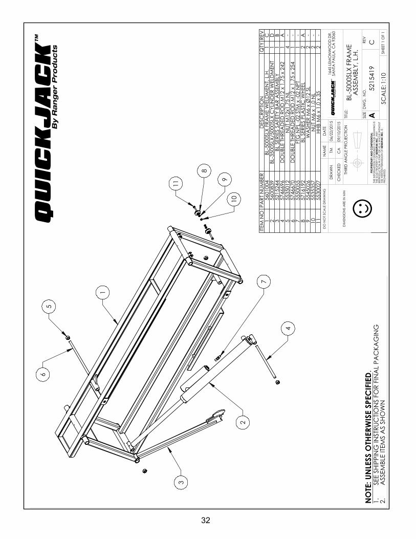
32
DIM
ENSI
ON
S A
RE IN
MM
☺
1
4
2
7
8
113
56
910
NEX
T A
SSEM
BLY
5215
249
5260
113
REV
ISIO
NRE
VD
ESC
RIPT
ION
DA
TEED
ITED
BY
ECO
#A
PRO
DUC
TION
REL
EASE
, DER
IVED
FRO
M 5
2156
6506
/23/
2015
TM00
707
BRE
PLA
CED
553
0313
WITH
574
6696
, AD
DED
(1)
5535
012,
UPD
ATE
D B
OM
REV
ISIO
NS
08/0
5/20
15TM
0071
6
CUP
DA
TED
BO
M R
EVIS
ION
08/2
6/20
15TM
0072
2
ITEM
NO
PART
NUM
BER
DES
CRI
PTIO
NQ
TYRE
V1
5601
004
BL-5
000S
LX F
RAM
E W
ELD
MEN
T, L
.H.
1C
256
0083
9BL
-350
0SLX
/500
0SLX
CYL
IND
ER W
ELD
MEN
T1
D3
5215
244
BL S
ERIE
S SA
FETY
BA
R A
SSEM
BLY
1B
457
4669
6D
OUB
LE T
HREA
DED
RO
D M
12 x
1.7
5 x
242
1A
555
3501
2N
UT M
12x1
.75
NL
4-
657
4667
0D
OUB
LE T
HREA
DED
RO
D M
12 x
1.7
5 x
254
1-
755
5005
5FT
G N
PL -0
2 ST
M x
-02
NPT
1-
857
1619
2BL
SER
IES
PLA
STIC
WHE
EL2
A9
5545
026
WA
SHER
M6
x Ø
12 S
L2
-10
5535
357
NUT
M6
x 1.
0 N
L2
-11
5530
027
HHB
M6
x 1.
0 x
352
-
SHE
ET 1
OF
1
REV
DW
G.
NO
.
ASIZE
TITLE
:
NA
ME
DA
TE
CHE
CKE
D
DRA
WN
C
1645
LEM
ON
WO
OD
DR.
SAN
TA P
AUL
A, C
A 9
3060
PRO
PRIE
TARY
AN
D C
ON
FIDE
NTIA
LTH
E IN
FORM
ATIO
N C
ON
TAIN
ED IN
THI
S D
RAW
ING
IS
THE
SOLE
PRO
PERT
Y O
F BE
NDP
AK
INC
. AN
Y RE
PRO
DUC
TION
IN P
ART
OR
AS
A W
HOLE
WITH
OUT
TH
E W
RITT
EN P
ERM
ISSI
ON
OF
BEN
DPA
K IN
C. I
S PR
OHI
BITE
D.
NO
TE: U
NLE
SS O
THER
WIS
E SP
ECIF
IED.
TM
5215
419
BL-5
000S
LX F
RAM
E A
SSEM
BLY,
L.H
.
06/2
2/20
15
DO
NO
T SC
ALE
DRA
WIN
G
1:10
SCA
LE:
THIR
D A
NG
LE P
ROJE
CTIO
N
CA
09/1
0/20
15
SEE
SHIP
PIN
G IN
STRU
CTIO
NS
FOR
FIN
AL
PAC
KAG
ING
1.A
SSEM
BLE
ITEM
S A
S SH
OW
N2.
QU
ICK
JA
CK
™
By R
an
ge
r P
rod
uc
ts
QU
ICK
JA
CK
™
By R
an
ge
r P
rod
uc
ts
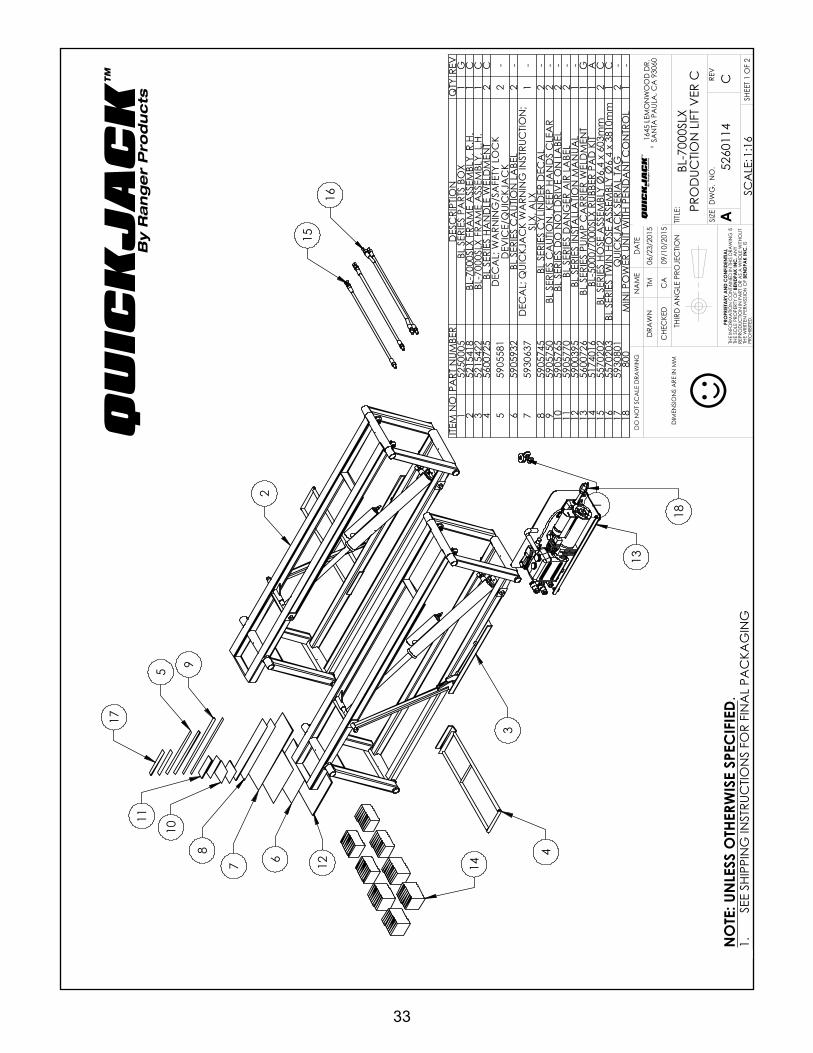
33
DIM
ENSI
ON
S A
RE IN
MM
☺
2
4
1
5
67
89
10
11
12
3
14
13
15
16
17
18
IN H
OUS
E O
NLY
, N
OT F
OR
PRO
DUC
TION
ITEM
NO
PART
NUM
BER
DES
CRI
PTIO
NQ
TYRE
V1
5250
005
BL S
ERIE
S PA
RTS
BOX
1G
252
1541
8BL
-700
0SLX
FRA
ME
ASS
EMBL
Y, R
.H.
1C
352
1542
2BL
-700
0SLX
FRA
ME
ASS
EMBL
Y, L
.H.
1C
456
0072
5BL
SER
IES
HAN
DLE
WEL
DM
ENT
2C
559
0558
1D
ECA
L; W
ARN
ING
/SA
FETY
LO
CK
DEV
ICE/
QUI
CKJ
AC
K2
-6
5905
932
BL S
ERIE
S C
AUT
ION
LA
BEL
2-
759
3063
7D
ECA
L; Q
UIC
KJA
CK
WA
RNIN
G IN
STRU
CTIO
N;
SLX,
ALX
1-
859
0574
5BL
SER
IES
CYL
IND
ER D
ECA
L2
-9
5905
750
BL S
ERIE
S C
AUT
ION
, KEE
P HA
ND
S C
LEA
R2
-10
5905
765
BL S
ERIE
S D
O N
OT
DRI
VE
ON
LA
BEL
2-
1159
0577
0BL
SER
IES
DA
NG
ER A
IR L
ABE
L2
-12
5900
395
BL S
ERIE
S IN
STA
LLA
TION
MA
NUA
L1
-13
5600
726
BL S
ERIE
S PU
MP
CA
RRIE
R W
ELD
MEN
T1
G14
5174
016
BL-5
000/
7000
SLX
RUBB
ER P
AD
KIT
1A
1555
7020
2BL
SER
IES
HOSE
ASS
EMBL
Y Ø
6.4
x 60
3mm
2C
1655
7020
3BL
SER
IES
TWIN
HO
SE A
SSEM
BLY
Ø6.
4 x
3810
mm
1C
1759
3080
1Q
UIC
KJA
CK
SERI
AL
TAG
2-
1880
0M
INI P
OW
ER U
NIT
WITH
PEN
DA
NT
CO
NTR
OL
1-
REV
ISIO
NRE
VD
ESC
RIPT
ION
DA
TEED
ITED
BY
ECO
#A
IN H
OUS
E, N
OT
FOR
PRO
DUC
TION
, DER
IVED
FR
OM
526
0111
06/2
6/20
15TM
0070
7
BRE
PLA
CED
590
5933
WITH
593
0637
, UPD
ATE
D
BOM
REV
ISIO
NS
08/1
0/20
15TM
0071
6
CA
DD
ED 8
00, R
EPLA
CED
517
4675
WITH
517
4016
, UP
DA
TED
BO
M R
EVIS
ION
S09
/02/
2015
TM00
722
SHE
ET 1
OF
2
REV
DW
G.
NO
.
ASIZE
TITLE
:
NA
ME
DA
TE
CHE
CKE
D
DRA
WN
C
1645
LEM
ON
WO
OD
DR.
SAN
TA P
AUL
A, C
A 9
3060
PRO
PRIE
TARY
AN
D C
ON
FIDE
NTIA
LTH
E IN
FORM
ATIO
N C
ON
TAIN
ED IN
THI
S D
RAW
ING
IS
THE
SOLE
PRO
PERT
Y O
F BE
NDP
AK
INC
. AN
Y RE
PRO
DUC
TION
IN P
ART
OR
AS
A W
HOLE
WITH
OUT
TH
E W
RITT
EN P
ERM
ISSI
ON
OF
BEN
DPA
K IN
C. I
S PR
OHI
BITE
D.
NO
TE: U
NLE
SS O
THER
WIS
E SP
ECIF
IED.
TM
5260
114
BL-7
000S
LX
PRO
DUC
TION
LIF
T V
ER C
06/2
3/20
15
DO
NO
T SC
ALE
DRA
WIN
G
1:16
SCA
LE:
THIR
D A
NG
LE P
ROJE
CTIO
N
CA
09/1
0/20
15
SEE
SHIP
PIN
G IN
STRU
CTIO
NS
FOR
FIN
AL
PAC
KAG
ING
1.
QU
ICK
JA
CK
™
By R
an
ge
r P
rod
uc
ts
QU
ICK
JA
CK
™
By R
an
ge
r P
rod
uc
ts

34
DIM
ENSI
ON
S A
RE IN
MM
☺
1
4
2
7
8
11
3
56
910
NEX
T A
SSEM
BLY
5215
349
5260
113
REV
ISIO
NRE
VD
ESC
RIPT
ION
DA
TEED
ITED
BY
ECO
#A
PRO
DUC
TION
REL
EASE
, DER
IVED
FRO
M 5
2156
6206
/23/
2015
TM00
707
BRE
PLA
CED
553
0313
WITH
574
6696
, AD
DED
(1)
5535
012,
UPD
ATE
D B
OM
REV
ISIO
NS
08/0
5/20
15TM
0071
6C
UPD
ATE
D B
OM
REV
ISIO
NS
08/2
6/20
15TM
0072
2
ITEM
NO
PART
NUM
BER
DES
CRI
PTIO
NQ
TYRE
V1
5601
003
BL-5
000S
LX F
RAM
E W
ELD
MEN
T, R
.H.
1C
256
0083
9BL
-350
0SLX
/500
0SLX
CYL
IND
ER W
ELD
MEN
T1
D3
5215
244
BL S
ERIE
S SA
FETY
BA
R A
SSEM
BLY
1B
457
4669
6D
OUB
LE T
HREA
DED
RO
D M
12 x
1.7
5 x
242
1A
555
3501
2N
UT M
12x1
.75
NL
4-
657
4667
0D
OUB
LE T
HREA
DED
RO
D M
12 x
1.7
5 x
254
1C
755
5005
5FT
G N
PL -0
2 ST
M x
-02
NPT
1-
857
1619
2BL
SER
IES
PLA
STIC
WHE
EL2
A9
5545
026
WA
SHER
M6
x Ø
12 S
L2
-10
5535
357
NUT
M6
x 1.
0 N
L2
-11
5530
027
HHB
M6
x 1.
0 x
352
-
SHE
ET 1
OF
1
REV
DW
G.
NO
.
ASIZE
TITLE
:
NA
ME
DA
TE
CHE
CKE
D
DRA
WN
C
1645
LEM
ON
WO
OD
DR.
SAN
TA P
AUL
A, C
A 9
3060
PRO
PRIE
TARY
AN
D C
ON
FIDE
NTIA
LTH
E IN
FORM
ATIO
N C
ON
TAIN
ED IN
THI
S D
RAW
ING
IS
THE
SOLE
PRO
PERT
Y O
F BE
NDP
AK
INC
. AN
Y RE
PRO
DUC
TION
IN P
ART
OR
AS
A W
HOLE
WITH
OUT
TH
E W
RITT
EN P
ERM
ISSI
ON
OF
BEN
DPA
K IN
C. I
S PR
OHI
BITE
D.
NO
TE: U
NLE
SS O
THER
WIS
E SP
ECIF
IED.
TM
5215
417
BL-5
000S
LX F
RAM
E A
SSEM
BLY,
R.H
.
06/2
3/20
15
DO
NO
T SC
ALE
DRA
WIN
G
1:10
SCA
LE:
THIR
D A
NG
LE P
ROJE
CTIO
N
CA
09/1
0/20
15
SEE
SHIP
PIN
G IN
STRU
CTIO
NS
FOR
FIN
AL
PAC
KAG
ING
1.A
SSEM
BLE
ITEM
S A
S SH
OW
N2.
QU
ICK
JA
CK
™
By R
an
ge
r P
rod
uc
ts
QU
ICK
JA
CK
™
By R
an
ge
r P
rod
uc
ts

35
DIM
ENSI
ON
S A
RE IN
MM
☺
4
2
7
8
11
3
56
910
1
NEX
T A
SSEM
BLY
5215
248
5260
114
REV
ISIO
NRE
VD
ESC
RIPT
ION
DA
TEED
ITED
BY
ECO
#A
PRO
DUC
TION
REL
EASE
, DER
IVED
FRO
M 5
2156
6206
/26/
2015
TM00
707
BRE
PLA
CED
553
0269
WITH
574
6696
, AD
DED
(1)
5535
012,
UPD
ATE
D B
OM
REV
ISIO
NS
08/0
5/20
15TM
0071
6
CUP
DA
TED
BO
M R
EVIS
ION
08/3
1/20
15TM
0072
2
ITEM
NO
PART
NUM
BER
DES
CRI
PTIO
NQ
TYRE
V1
5601
005
BL-7
000S
LX F
RAM
E W
ELD
MEN
T, R
.H.
1C
256
0084
0BL
-700
0SLX
CYL
IND
ER W
ELD
MEN
T1
C3
5215
244
BL S
ERIE
S SA
FETY
BA
R A
SSEM
BLY
1B
457
4669
6D
OUB
LE T
HREA
DED
RO
D M
12 x
1.7
5 x
242
1A
555
3501
2N
UT M
12x1
.75
NL
4-
657
4614
2D
OUB
LE T
HREA
DED
RO
D M
12 x
1.7
5 x
274
1A
755
5005
5FT
G N
PL -0
2 ST
M x
-02
NPT
1-
857
1619
2BL
SER
IES
PLA
STIC
WHE
EL2
A9
5545
026
WA
SHER
M6
x Ø
12 S
L2
-10
5535
357
NUT
M6
x 1.
0 N
L2
-11
5530
027
HHB
M6
x 1.
0 x
352
-
SHE
ET 1
OF
1
REV
DW
G.
NO
.
ASIZE
TITLE
:
NA
ME
DA
TE
CHE
CKE
D
DRA
WN
C
1645
LEM
ON
WO
OD
DR.
SAN
TA P
AUL
A, C
A 9
3060
PRO
PRIE
TARY
AN
D C
ON
FIDE
NTIA
LTH
E IN
FORM
ATIO
N C
ON
TAIN
ED IN
THI
S D
RAW
ING
IS
THE
SOLE
PRO
PERT
Y O
F BE
NDP
AK
INC
. AN
Y RE
PRO
DUC
TION
IN P
ART
OR
AS
A W
HOLE
WITH
OUT
TH
E W
RITT
EN P
ERM
ISSI
ON
OF
BEN
DPA
K IN
C. I
S PR
OHI
BITE
D.
NO
TE: U
NLE
SS O
THER
WIS
E SP
ECIF
IED.
TM
5215
418
BL-7
000S
LX F
RAM
E A
SSEM
BLY,
R.H
.
06/2
6/20
15
DO
NO
T SC
ALE
DRA
WIN
G
1:10
SCA
LE:
THIR
D A
NG
LE P
ROJE
CTIO
N
CA
09/1
0/20
15
SEE
SHIP
PIN
G IN
STRU
CTIO
NS
FOR
FIN
AL
PAC
KAG
ING
1.A
SSEM
BLE
ITEM
S A
S SH
OW
N2.
QU
ICK
JA
CK
™
By R
an
ge
r P
rod
uc
ts
QU
ICK
JA
CK
™
By R
an
ge
r P
rod
uc
ts

36
DIM
ENSI
ON
S A
RE IN
MM
☺
1
4
2
7
8
113
56
910
NEX
T A
SSEM
BLY
5215
247
5260
114
REV
ISIO
NRE
VD
ESC
RIPT
ION
DA
TEED
ITED
BY
ECO
#A
PRO
DUC
TION
REL
EASE
, DER
IVED
FRO
M 5
2156
6506
/26/
2015
TM00
707
BRE
PLA
CED
553
0269
WITH
574
6696
, AD
DED
(1)
5535
012,
UPD
ATE
D B
OM
REV
ISIO
NS
08/0
5/20
15TM
0071
6C
UPD
ATE
D B
OM
REV
ISIO
N08
/31/
2015
TM00
722
ITEM
NO
PART
NUM
BER
DES
CRI
PTIO
NQ
TYRE
V1
5601
006
BL-7
000S
LX F
RAM
E W
ELD
MEN
T, L
.H.
1C
256
0084
0BL
-700
0SLX
CYL
IND
ER W
ELD
MEN
T1
C3
5215
244
BL S
ERIE
S SA
FETY
BA
R A
SSEM
BLY
1B
457
4669
6D
OUB
LE T
HREA
DED
RO
D M
12 x
1.7
5 x
242
1A
555
3501
2N
UT M
12x1
.75
NL
4-
657
4614
2D
OUB
LE T
HREA
DED
RO
D M
12 x
1.7
5 x
274
1A
755
5005
5FT
G N
PL -0
2 ST
M x
-02
NPT
1-
857
1619
2BL
SER
IES
PLA
STIC
WHE
EL2
A9
5545
026
WA
SHER
M6
x Ø
12 S
L2
-10
5535
357
NUT
M6
x 1.
0 N
L2
-11
5530
027
HHB
M6
x 1.
0 x
352
-
SHE
ET 1
OF
1
REV
DW
G.
NO
.
ASIZE
TITLE
:
NA
ME
DA
TE
CHE
CKE
D
DRA
WN
C
1645
LEM
ON
WO
OD
DR.
SAN
TA P
AUL
A, C
A 9
3060
PRO
PRIE
TARY
AN
D C
ON
FIDE
NTIA
LTH
E IN
FORM
ATIO
N C
ON
TAIN
ED IN
THI
S D
RAW
ING
IS
THE
SOLE
PRO
PERT
Y O
F BE
NDP
AK
INC
. AN
Y RE
PRO
DUC
TION
IN P
ART
OR
AS
A W
HOLE
WITH
OUT
TH
E W
RITT
EN P
ERM
ISSI
ON
OF
BEN
DPA
K IN
C. I
S PR
OHI
BITE
D.
NO
TE: U
NLE
SS O
THER
WIS
E SP
ECIF
IED.
TM
5215
422
BL-7
000S
LX F
RAM
E A
SSEM
BLY,
L.H
.
06/2
6/20
15
DO
NO
T SC
ALE
DRA
WIN
G
1:10
SCA
LE:
THIR
D A
NG
LE P
ROJE
CTIO
N
CA
09/1
0/20
15
SEE
SHIP
PIN
G IN
STRU
CTIO
NS
FOR
FIN
AL
PAC
KAG
ING
1.A
SSEM
BLE
ITEM
S A
S SH
OW
N2.
QU
ICK
JA
CK
™
By R
an
ge
r P
rod
uc
ts
QU
ICK
JA
CK
™
By R
an
ge
r P
rod
uc
ts

37
DIM
ENSI
ON
S A
RE IN
MM
☺
ISO
MET
RIC
VIE
WFO
R RE
FERE
NC
E O
NLY
DO
NO
T SC
ALE
1
2
3
NEX
T A
SSEM
BLY
5215
415
5215
416
5215
417
5215
418
5215
419
5215
422
REV
ISIO
NRE
VD
ESC
RIPT
ION
DA
TEED
ITED
BY
ECO
#A
PRO
DUC
TION
REL
EASE
, DER
IVED
FRO
M 5
2155
9406
/10/
2015
TM00
707
BUP
DA
TED
BO
M R
EVIS
ION
S08
/05/
2015
TM00
716
ITEM
NO
PART
NUM
BER
DES
CRI
PTIO
NQ
TYRE
V1
5601
009
BL S
ERIE
S SA
FETY
ARM
WEL
DM
ENT
1B
257
3688
7BL
SER
IES
SAFE
TY L
ATC
H1
A3
5505
028
SPRI
NG
PIN
M6
x 20
2--
SHE
ET 1
OF
1
REV
DW
G.
NO
.
ASIZE
TITLE
:
NA
ME
DA
TE
CHE
CKE
D
DRA
WN
B
1645
LEM
ON
WO
OD
DR.
SAN
TA P
AUL
A, C
A 9
3060
PRO
PRIE
TARY
AN
D C
ON
FIDE
NTIA
LTH
E IN
FORM
ATIO
N C
ON
TAIN
ED IN
THI
S D
RAW
ING
IS
THE
SOLE
PRO
PERT
Y O
F BE
NDP
AK
INC
. AN
Y RE
PRO
DUC
TION
IN P
ART
OR
AS
A W
HOLE
WITH
OUT
TH
E W
RITT
EN P
ERM
ISSI
ON
OF
BEN
DPA
K IN
C. I
S PR
OHI
BITE
D.
NO
TE: U
NLE
SS O
THER
WIS
E SP
ECIF
IED.
TM
5215
244
BL S
ERIE
S SA
FETY
BA
R A
SSEM
BLY
06/1
0/20
15
DO
NO
T SC
ALE
DRA
WIN
G
1:3
SCA
LE:
THIR
D A
NG
LE P
ROJE
CTIO
N
CA
08/1
1/20
15
ASS
EMBL
E ITE
MS
AS
SHO
WN
1.
QU
ICK
JA
CK
™
By R
an
ge
r P
rod
uc
ts
QU
ICK
JA
CK
™
By R
an
ge
r P
rod
uc
ts

38
QU
ICK
JA
CK
™
By R
an
ge
r P
rod
uc
ts
POW
ER-U
NIT-
SCHE
MA
TIC
1
2V -
DCRe
d T
erm
inal
Blac
k Te
rmin
al
*Min
imum
requ
irem
ent f
orJu
mpe
r Cab
les i
n th
e U
SA
shou
ld b
e: 7
Gau
ge.
For E
urop
ean
coun
tries
:10
squa
re m
illim
eter
s.


40
FOR PARTS OR SERVICE CONTACT:
QuickJack1645 Lemonwood Dr.
Santa Paula, CA 930601-805-421-5114
Toll Free: 1-888-262-3880www.quickjack.com
EN ESPAÑOL: www.quickjack.com.mx
QUICKJACK ™
By Ranger Products
P/N 5900395
NOTE:
Every effort has been taken to ensure complete and accurate instructions have been included in this manual, however, possible product updates, revisions and or changes may have occurred since this printing. Quickjack™ reserves the right to change specifications without incurring any obligation for equipment previously or subsequently sold.