important! - restroomplus.com braced-baked ename… · important! read this entire ... refer to the...
TRANSCRIPT

P.O. Box 309, Menomonee Falls, WI53052-0309TEL. 1-800-BRADLEY FAX 262-251-5817http://www.bradleycorp.com
Baked Enamel & Stainless SteelFloor-Mounted Overhead-BracedRestroom Partitions - Series 400
Installation
ADA•
CO
M
PLIANT
Table of ContentsLayout Dimensions ........................................2–3Mounting Stirrup Brackets.................................4Pilaster Hardware...............................................5Panels & Pilasters ..............................................6Headrail ..............................................................7Hinges ............................................................8–9Slide Latch & Strike/Keeper ......................10–11
Installation for Optional ComponentsMounting Continuous Brackets .................12–14Telescoping Pilaster .........................................15Wall-Hung Pilaster .....................................16–17Continuous Piano Hinge ..................................18Flat Hinge.........................................................19Surface-Mounted Slide Latch ....................20–21Double Door Pull .............................................22
HDWT-INSTR-009 Rev. D; EN 07-1417© 2008 Bradley CorporationPage 1 of 22 2/5/08
IMPORTANT!Read this entire installation manual to ensure proper installation. When finished with theinstallation, file this manual with the owner or maintenance department. Compliance andconformity to local codes and ordinances is the responsibility of the installer.
Separate parts from packaging and make sure all parts are accounted for before discardingpackaging material. If parts are missing, do not begin installation until you obtain the missingparts. Leave the protective masking on until installation is complete. To prevent warping,always lay the material flat. Do not lean the material against the wall or stack unevenly.
Product warranties may be found under "Products" on our web site at www.bradleycorp.com.
THIS
SIDE
UP
Packing List
••••
Installation
For Standard HeightDoors and Panels Only

2
Baked Enamel & Stainless Steel Overhead Braced Restroom PartitionsSeries 400 Installation
2/5/08 The Mills Company • HDWT-INSTR-009 Rev. D; EN 07-1417
Supplies required:• Chalk line and pencil • Tape measure and 4' level• Jigsaw or hacksaw • Two spring clamps• 9/64", 3/16", 7/32" and 1/4" drill bits • Power drill or screw gun with drill bit extension• 5/16" ceramic tile and masonry drill bit • Hammer drill• Circular saw • Spacer, 12" high and deep enough to support panel
Hardware Supplied
Installation InstructionsStep 1: Layout Dimensions - Stirrup Brackets
NOTE: When installing the partition components, consult the applicable Mills Partition submittaldrawing for compartment layout dimensions.
1. To locate the pilaster centerline, measure from the back wall forward to the face of thecompartment (Figure 1b “A”), subtract 5/8" and mark this location on the floor. Mark the samemeasurement on the opposite end of your layout (Figure 1b “A1”) and draw a straight lineconnecting both marks.FOR FREESTANDING (FS) PARTITIONS: Refer to submittal drawings and determine theapproximate location of the outside panels. Establish dimensions “A” and “A1” as explainedabove.
2. To locate the panel centerline, measure the stall width across the back wall and place a mark atthe base of the rear wall (Figure 1b “B”). Repeat this step for each panel, starting eachmeasurement from the last panel centerline (Figure 1b “B1”).
3. To locate the stirrup brackets, draw a plumb line on all walls from each pilaster and panel center.From the highest point in the room, measure 18" and 64" from the floor and place a mark on thepilaster/panel plumb line. These marks represent the hole center line of the stirrup brackets. Usea level to transfer that mark to all other plumb lines (Figure 1b “C”).
#10-12PLASTIC ANCHOR
FAST-T281
#14 x 2" BUTTON HDSHEET METAL SCREW
TORX-T27 DRIVEFAST-Z002
#14 x 5/8" BUTTON HDSHEET METAL SCREW
TORX-T27 DRIVEFAST-Z0016
#10 x 3/4" FLAT HDSHEET METAL SCREW
TORX-T25 DRIVEFAST-Z0006
#10-24 x 1-3/8" BUTTON HDSHOULDER SCREW
TORX-T27 DRIVEFAST-Z0003
#10-24x3/4" BUTTON HDSHOULDER SCREW
TORX-T27 DRIVEFAST-Z004
#10-24 x 1" BUTTON HDSHOULDER SCREW
TORX-T27 DRIVEFAST-Z004A
#10-24 x 3/4" BUTTON HDBARREL NUT
TORX-T27 DRIVEFAST-Z003
#10 x 5/8" BUTTON HDSHEET METAL SCREW
TORX-T27 DRIVEFAST-Z0019
#14 x 5/8" BUTTON HDSELF-TAPPING SCREW
TORX-T27 DRIVEFAST-S355A
#10 x 2 FLAT HDSHEET METAL SCREW
TORX-T25 DRIVEFAST-Z0023
#5-40 x 5/8" FLAT HDMACHINE SCREWTORX-T10 DRIVE
FAST-T300
#14-16PLASTIC ANCHOR
FAST-T373
#8 x 5/8" FLAT HDSHEET METAL SCREW
TORX-T10 DRIVEFAST-T346

PILASTERPLUMB
LINE
*"C"
*"C"
*"C"
*"C"
PANELPLUMB
LINE
PILASTERCENTER
LINE
CL CL
CL
CL CL
CL
"A" "B"
"A1"
"B1"
*"C"
*"C"
18"
64"
Figure 1b - Stirrup Bracket Installation
(26")
(36")
3" 36" 24" 26" 8"
60-1/2"WALL TO
CENTER LINE
36"CENTER TOCENTER
1"GAP
61-1/4"TO
FACE
1/2"GAP
1"GAP
20-1
/2"
3-1/
2"
6-1/
2"1-
1/2"
3"
(58-
1/2"
)
(58-
1/2"
)
3
Baked Enamel & Stainless Steel Overhead Braced Restroom PartitionsInstallation Series 400
The Mills Company • HDWT-INSTR-009 Rev. D; EN 07-1417 2/5/08
Figure 1a - Submittal Drawing Example

2/5/08 The Mills Company • HDWT-INSTR-009 Rev. D; EN 07-1417
PILASTER
SPLIT
SPLIT
63-7/16"
STIRRUPBRACKET
17-7/16"
#14 X 5/8"SCREW
CL
OF "U"BRACKET
CL
4
Baked Enamel & Stainless Steel Overhead Braced Restroom PartitionsSeries 400 Installation
Installation Instructions continued . . .Step 2: Install Stirrup Brackets to Wall
NOTE: Refer to Figure 2a for two-eared brackets and Figure 2bfor one-eared brackets.
1. Place the center of the stirrup bracket at each establishedlevel line. Center the bracket opening on the pilaster/panelplumb line. Using the bracket as a template, mark the holelocations on the wall. Remove the bracket and drill a 5/16"dia. hole (min. 2" deep) at each hole location.
2. Insert plastic anchors and secure brackets to the wall withfasteners provided.
Step 3: Install Stirrup Brackets to PilasterNOTE: Refer to Figure 3a for “U” brackets, Figure 3b for alcovebrackets and Figure 3c for one-eared brackets.
1. Refer to the submittal drawing to locate the split dimension ofthe pilaster bracket.
2. To locate the brackets, measure down from the top of thepilaster and place a mark on the pilaster split centerline asshown. These marks represent the level line for the stirrupbrackets.
3. Place the center of the stirrup bracket at each establishedlevel line. Center the bracket opening on the panel plumbline. Using the bracket as a template, mark the hole locationson the pilaster. Remove the bracket and drill a 3/16" dia. pilothole (through inside face of pilaster only) at each location.
Do not permit drill bit to touch outside face of pilaster.4. Secure the brackets to the pilasters using the hardware
provided for “U” brackets or alcove brackets.
STIRRUPBRACKET
PLASTICANCHOR
#14 x 2"SCREW
PANEL PLUMBLINE
FLOOR
STIRRUPBRACKET
#14 x 2"SCREW
PILASTER/PANELPLUMB LINE
FLOOR
ESTABLISHEDLEVEL LINE
ESTABLISHEDLEVEL LINE
PLASTICANCHOR
Figure 2a - Two-eared Bracket
Figure 3a - “U” Bracket
Figure 2b - One-eared Bracket
PILASTER
CL
ALCOVEBRACKET
#14 x 5/8"SCREW
63-7/16"
17-7/16"
Figure 3b - Alcove Bracket
PILASTER
SPLIT
SPLIT
63-7/16"
STIRRUPBRACKET
17-7/16"
#14 X 5/8"SCREW
CL
OF "U"BRACKET
CL
Figure 3c - One-Eared Bracket

5
Baked Enamel & Stainless Steel Overhead Braced Restroom PartitionsInstallation Series 400
The Mills Company • HDWT-INSTR-009 Rev. D; EN 07-1417 2/5/08
Installation Instructionscontinued . . .
Step 4: Install Pilaster MountingHardware
1. Refer to your submittal drawings todetermine placement of the anchorson the pilaster centerline (see Figure4a).
2. Drill 5/16" dia. x 2" minimum deepholes in the floor and remove all dirtand debris from the holes.
3. Insert the plastic anchors into theholes and secure as shown in Figure4b.
4. Repeat procedures #2–3 forremaining hole locations.
PILASTERCENTERLINE
3" 38" 22" 28" 5"DOOR
OPENINGDOOR
OPENING
Figure 4a - Anchor Placement Example
BASECLIP
PLASTICANCHOR
LEVELINGBRACKET
#14 x 2"SCREW
Figure 4b - Pilaster Mounting Hardware
PILASTERWIDTH
1" TYP.

6
Baked Enamel & Stainless Steel Overhead Braced Restroom PartitionsSeries 400 Installation
2/5/08 The Mills Company • HDWT-INSTR-009 Rev. D; EN 07-1417
Installation Instructions continued . . .Step 5: Install Panels and Pilasters
NOTE: Start at one end and install a panel, then a pilaster. Continue alternating until installation iscomplete. When installing in an alcove or in-corner alcove, use an alcove bracket to secure thepilaster to the panel.
1. Using a 12" spacer to help support the panel weight, place a panel on the spacer and insert thepanel into the stirrup bracket. Adjust the panel height to maintain the 6" dim. shown in Figure 5a.
2. Thread the leveling bolt into the leveling bar leaving 3/4" of the bolt exposed (see inset below).3. Slide the shoes carefully over the mounting end of the pilasters and leave approximately 5"
above bottom end.4. Place the pilaster between the “L” brackets and fasten loosely with screws at pre-drilled
locations on each side (see Figure 5b).NOTE: Refer to your submittal drawing and leave the appropriate gap (standard gap is 1/2") betweenthe panel and the pilaster (see Figure 5c).
5. Make sure the pilasters are plumb and level to each other. The pilaster height can be adjusted bymoving the leveling bolt to achieve the 6" dim. as shown. Using the stirrup bracket as a template,drill a 3/16" dia. hole in the panel. Secure the panel to the pilaster with fasteners provided.
NOTE: Refer to your submittal drawing and leave the appropriate gap (standard gap is 1") betweenthe panel and the wall.
6. Using the stirrup brackets as a template, drill a 3/16" dia. hole in the panel. Secure the panel tothe bracket with fasteners provided.
7. Repeat procedures 1–6 to install remaining pilasters and panels.
PILASTER
#14 x 5/8"SCREW
5/16 x 3"LEVELING
BOLT
12" A.F.F.
PANEL
STANDARD1/2" GAP
STIRRUPBRACKET
PANEL
#14 x 5/8"SCREW
6"
6"
SHOE
STIRRUPBRACKET
Figure 5bFigure 5a Figure 5c
LEVELINGBOLT

7
Baked Enamel & Stainless Steel Overhead Braced Restroom PartitionsInstallation Series 400
The Mills Company • HDWT-INSTR-009 Rev. D; EN 07-1417 2/5/08
Installation Instructions continued . . .Step 6: Headrail
NOTE: Refer to Figure 6 when installing the headrail.
1. Place the headrail across the top of the pilasters and slide it tight against the side wall. Mark theoutline of the headrail on the wall and remove the headrail.
2. Place the headrail bracket on the outline marked on the wall. Mark the bracket mounting holesand drill a 5/16" dia. hole (minimum 2" deep). Install wall anchors.
3. Secure the headrail bracket to the wall anchors using fasteners provided.4. Place the headrail across the top of the pilasters and slide it tight into the mounting bracket. Use
the headrail bracket as a template and drill a 1/4" dia. hole through the headrail.5. Secure the headrail to the bracket using hardware provided.6. Make sure that the pilaster is plumb. Leave the appropriate door opening between the pilasters as
shown on your submittal drawing. Securely tighten the pilaster mounting hardware on the floor7. On the back of the first pilaster, drill a 7/32" dia. hole through one face of the headrail only.
Using this hole as a template, drill a 9/64" dia. pilot hole through one face of the pilaster only.8. Secure the headrail to the back of the first pilaster using the fasteners provided.9. Carefully slide the shoe down the pilaster and snap into the shoe clip (see Figure 6a).
10. Repeat Procedures 6–9 to secure the headrail to the remaining pilasters.
PILASTER
#10 x 5/8" SCREW
#14 x 2" SCREW
#10-24 x 3/4"BARREL NUT
PLASTIC ANCHOR
HEADRAILBRACKET
#10-24 x 1-3/8SHOULDER SCREW
ENDCAP
HEADRAIL
Figure 6 - Install the headrails
SHOE
SHOE CLIP
Figure 6a

Installation Instructions continued . . .Step 7: Install Gravity-CamHinges
NOTE: Before installing the hinges,make sure the door openings are theappropriate size, the pilasters areplumb, and the headrail is installed.Refer to Figures 7a–7d found on pages8–9.
1. Determine the door swing byfacing the compartment from theoutside. The Mills submittaldrawings will detail the specificdoor swing.
2. To locate the pilaster hinge,measure from the top of thepilaster and mark a level line asshown in Figure 7a. This linerepresents the upper hole locationof the top and bottom hinge.
3. Using the hinge as a template,drill 1/4" dia. holes through thepilaster. Secure the top andbottom pilaster hinge to thepilaster with the hardwareprovided (see Figure 7b).
4. Assemble the bottom hinge camand pin (see Figure 7c). Threadthe locknut loosely onto the bottom hinge pin.
5. Place the bottom door hinge into the bottom pilasterhinge. Place the top door hinge into the top pilasterhinge, then insert the top hinge pin (see Figure 7d,page 9).
NOTE: The top hinge pin should snap securely into place.6. Rotate the door to the desired “at rest” position.
Push down on the door while holding it in the “atrest” position. This sets the male and female cams inthe bottom hinge. For doors requiring a full close,rotate the door 15° past the closed position, thentighten the hex nut to secure the door in the “at rest”position.
7. Repeat Procedures 1–6 for remaining doors.
2-1/16"
56-3/16"
Wall-HungPilaster
(58")
13-1/2"
67-5/8"
Wall-HungPilaster
(69-9/16")
13-1/2"
67-5/8"
Figure 7a
Floor-MountedOverhead-Braced
Pilaster
13-1/2" 13-1/2"
67-5/8" 67-5/8" 56-3/16"
2-1/16"
8
Baked Enamel & Stainless Steel Overhead Braced Restroom PartitionsSeries 400 Installation
2/5/08 The Mills Company • HDWT-INSTR-009 Rev. D; EN 07-1417
#10-24 x 1"SHOULDER
SCREW
#10-24 x 3/4"BARREL NUT
TOP HINGE WITHNYLON BUSHING
Figure 7b

9
Baked Enamel & Stainless Steel Overhead Braced Restroom PartitionsInstallation Series 400
The Mills Company • HDWT-INSTR-009 Rev. D; EN 07-1417 2/5/08
BOTTOMHINGE CAM
LOCKNUT
TOP HINGEPIN (DOOR)
BOTTOMHINGE PIN
BOTTOM HINGE
Figure 7d
Figure 7c
Installation Instructions continued . . .

10
Baked Enamel & Stainless Steel Overhead Braced Restroom PartitionsSeries 400 Installation
2/5/08 The Mills Company • HDWT-INSTR-009 Rev. D; EN 07-1417
#5-40 x 5/8"FLAT HDMACHINESCREW
#10-24 x 3/4"BARREL NUT
DOOR PULL(ADDED FOR 34"& 36" DOORS)
STRIKE/KEEPER
ESCUTCHEON(OUTSIDEOF DOOR)
CONCEALEDLATCH#10-24 x 1"
SHOULDERSCREW
LATCH BOLT
#10 x 1-3/8"SHOULDER
SCREW
4"
Figure 8a - Inswing Door Hardware Details
#10 x 3/4"FLAT HEAD
SCREW
CONCEALEDLATCH
FLATSTRIKE/KEEPER
(INSWING)
COAT HOOK(INSWING)
3"
3"
#10 x 5/8" SHEETMETAL SCREW
Installation Instructions continued . . .Step 8a: Concealed Latch and Strike/keeper for Inswing Doors
NOTE: Refer to the details in Figure 8a when installing inswing doors. ADA COMPLIANT DOORS:When installing coat hook, wall bumper and door pull, refer to Figure 8b for proper location.
1. Assemble the latch as shown in Figure 8a. Tighten the fasteners and insert the latch bolt, pushingin until it snaps into place.
2. Place the strike/keeper on the pilaster and center it on the opposing latch bolt.3. Wrap Around Strike/Keeper Applications: Using the strike/keeper as a template, mark the
hole locations on the pilasters. Remove the strike/keeper and drill 1/4" dia. holes through thepilaster. Secure to the pilaster with fasteners provided.Flat Strike/Keeper Applications: Using the flat strike/keeper as a template, mark the holelocations on the pilasters. Remove the strike/keeper and drill 1/8" dia. holes through one face ofthe pilaster only. Secure to the pilaster with fasteners provided.
Do not permit drill bit to touch outside face of pilaster.4. Inswing ADA Doors: For 34" and 36" doors, drill a 1/4" dia. hole through the door and mount
the door pull to the inside of the door with fasteners provided.NOTE: Local codes vary from state to state. Check your local codes before installing coat hook.
5. Install the coat hook on the inside of the door on the latch side at a location 3" down from thetop and 3" in from the side. Using the coat hook as a template, drill two 9/64" dia. pilot holesthrough one face of the door only. Secure the coat hook using the fasteners provided.
Do not permit drill bit to touch outside face of door.6. Repeat Procedures 1–5 for remaining doors.
TYPICAL INSWING FLAT STRIKE/KEEPER

11
Baked Enamel & Stainless Steel Overhead Braced Restroom PartitionsInstallation Series 400
The Mills Company • HDWT-INSTR-009 Rev. D; EN 07-1417 2/5/08
FLATSTRIKE/KEEPER
(OUTSWING)
#10 x 3/4"FLAT HEAD
SCREW
CONCEALEDLATCH
DOORPULL
#10 x 1-3/8"SHOULDER
SCREW
Installation Instructions continued . . .Step 8b: Concealed Latch and Strike/keeper for Outswing Doors
NOTE: Refer to the details in Figure 8b when installing outswing doors.1. Assemble the latch as shown in Figure 8b. Tighten the fasteners and insert the latch bolt, pushing
in until it snaps into place.2. Place the strike/keeper on the pilaster and center it on the opposing latch bolt.3. Wrap Around Strike/Keeper Applications: Using the strike/keeper as a template, mark the
hole locations on the pilasters. Remove the strike/keeper and drill 1/4" dia. holes through thepilaster. Secure to the pilaster with fasteners provided.Flat Strike/Keeper Applications: Using the flat strike/keeper as a template, mark the holelocations on the pilasters. Remove the strike/keeper and drill 1/8" dia. holes through one face ofthe pilaster only. Secure to the pilaster with fasteners provided.
4. Drill a 1/4" dia. hole through the door and mount the door pull to the outside of the door usingthe fasteners provided.
5. Install the wall bumper on the outside of the door on the latch side at a location 3" up from thebottom and 3" over from the side. Using the wall bumper as a template, drill two 9/64" dia. pilotholes through one face of the door only. Secure the wall bumper using the fasteners provided.
Do not permit drill bit to touch outside face of door/pilaster.NOTE: Local codes vary from state to state. Check your local codes before installing coat hook.
6. Using the coat hook as a template, drill 3/16" dia. pilot holes. See Figure 8b for suggestedlocation.
Do not permit drill bit to touch outside face of door.7. Repeat Procedures 1–6 for remaining doors.
TYPICAL OUTSWINGFLAT STRIKE/KEEPER
WALL BUMPER(OUTSWING)3"
#10 x 5/8" SHEETMETAL SCREW
3"
CONCEALEDLATCH
#10 x 1-3/8SHOULDER
SCREW
DOORPULL
LATCH BOLT
ESCUTCHEON(OUTSIDEOF DOOR)
#5-40 x 5/8FLAT HEADMACHINESCREW
#10-24 x 1"SHOULDER
SCREW
#10-24 x 3/4"BARREL NUT
STRIKE/KEEPER
4"
#14 x 5/8"SCREW
COAT HOOK(OUTSWING)
36"A.F.F.
Figure 8b - Outswing Door Hardware Details

12
Baked Enamel & Stainless Steel Overhead Braced Restroom PartitionsSeries 400 Installation
2/5/08 The Mills Company • HDWT-INSTR-009 Rev. D; EN 07-1417
Installation Instructions for Optional ComponentsStep 1: Layout Dimensions - Continuous Brackets
NOTE: When installing the partition components, consult the applicable Mills Partition submittaldrawing for compartment layout dimensions.NOTE: The continuous brackets are optional components. For partitions with stirrup brackets, referto the stirrup bracket installation instructions found on page 2.
1. To locate the pilaster centerline, measure from the back wall forward to the face of thecompartment (Figure 10 “A”), subtract 5/8" and mark this location on the floor. Mark the samemeasurement on the opposite end of your layout (Figure 10 “A1”) and draw a straight lineconnecting both marks.FOR FREESTANDING (FS) PARTITIONS: Refer to submittal drawings and determine theapproximate location of the outside panels. Establish dimensions “A” and “A1” as explainedabove.
2. To locate the panel centerline, measure the stall width across the back wall and place a mark atthe base of the rear wall (Figure 10 “B”). Repeat this step for each panel, starting eachmeasurement from the last panel centerline (Figure 10 “B1”).
3. To locate the continuous brackets, draw a plumb line on all walls from each pilaster and panelcenter. From the highest point in the room, measure 12-1/2" (for stainless steel) or 12-1/4" (foraluminum) from the floor and place a mark on the pilaster/panel plumb line. Use a level totransfer that mark to all other plumb lines (Figure 10 “C”).
*"C"
*"C"
*"C"
PILASTERPLUMB
LINE
PANELPLUMB
LINE
PILASTERCENTER
LINE
CLCL
CL
CL
"A" "B"
"A1"
"B1" 12-1/2" FOR STAINLESS STEEL BRACKETS12-1/4" FOR ALUMINUM BRACKETS
TO BOTTOM OF BRACKET(HIGHEST POINT IN FLOOR)
Figure 10 - Centerline Layouts (continuous brackets)

13
Baked Enamel & Stainless Steel Overhead Braced Restroom PartitionsInstallation Series 400
The Mills Company • HDWT-INSTR-009 Rev. D; EN 07-1417 2/5/08
Installation Instructions continued . . .IMPORTANT: Brackets are used as templates but, since the hole patterns may be
different, the brackets may not be interchanged.Step 2: Install Continuous Brackets to Wall
NOTE: Refer to Figure 11a for one-eared brackets and Figure 11bfor two-eared brackets.
1. Place the bottom of the continuous bracket at the establishedlevel line. Center the bracket opening on the pilaster/panelplumb line. Using the bracket as a template, mark the holelocations on the wall. Remove the bracket and drill a 5/16"dia. hole (min. 2" deep) at each hole location.
2. Insert the plastic anchors and secure the brackets usingfasteners provided.
Step 3: Install Continuous Brackets to PilasterNOTE: Refer to Figure 11c for continuous aluminum “U”brackets, Figure 11d for stainless steel alcove brackets or Figure11e for continuous stainless steel “U” brackets.
1. Refer to the submittal drawing to locate the split dimension ofthe pilaster bracket.
2. To locate the top and bottom of the bracket, measure downfrom the top of the pilaster and place a mark on the pilastersplit centerline as shown.
3. Carefully position the bracket on the pilaster and drill a 3/16"dia. pilot hole through one face of the pilaster only at eachhole location.
Do not permit drill bit to touch outside face of pilaster.4. Secure the bracket to the pilasters using the fasteners
provided.
FLOOR
PLASTICANCHOR
ESTABLISHEDLEVEL LINE
#14 x 2"SCREW
CONTINUOUSBRACKET
PILASTER/PANELPLUMB LINE
FLOOR
PLASTICANCHOR
ESTABLISHEDLEVEL LINE
#14 x 2"SCREW
CONTINUOUSBRACKET
PANELPLUMB
LINE
Figure 11a - One-eared Bracket
Figure 11b - Two-eared Bracket
PLASTER
CONTINUOUSALUMINUMBRACKET
SPLIT
SPLIT
#14 x 5/8"SCREW
69-3/16"
11-11/16"
OF "U"BRACKET
CL
Figure 11c - ContinuousAluminum “U”
ALCOVEBRACKET
PLASTER
#14 x 5/8"SCREW
63-7/16"
17-7/16"
Figure 11d - Stainless SteelAlcove
68-15/16"SPLIT
#14 x 5/8"SCREW
11-15/16"
CONTINUOUSSTAINLESS
STEELBRACKET
SPLIT
PLASTER
OF "U"BRACKET
CL
Figure 11e - ContinuousStainless Steel “U”

14
Baked Enamel & Stainless Steel Overhead Braced Restroom PartitionsSeries 400 Installation
2/5/08 The Mills Company • HDWT-INSTR-009 Rev. D; EN 07-1417
Installation Instructions continued . . .Step 4: Install Continuous Brackets to Panels and Pilasters
NOTE: Start at one end and install a panel, then a pilaster. Continue alternating until installation iscomplete. When installing in an alcove or in-corner alcove, use an alcove bracket to secure thepilaster to the panel.
1. Using a 12" spacer to help support the panel weight, place a panel on the spacer and insert thepanel into the wall bracket (see Figure 12a).
2. Thread the leveling bolt into the leveling bar leaving 3/4" of the bolt exposed (see inset below).3. Slide the shoe carefully over the mounting end of the pilasters and leave approximately 5" above
the bottom end.4. Place the pilaster between the “L” brackets and fasten loosely with screws at pre-drilled
locations on each side (see Figure 12b)NOTE: Refer to your submittal drawing and leave the appropriate gap (standard gap is 1/2") betweenthe panel and the pilaster (see Figure 12c).
5. Make sure the pilasters are plumb and level to each other. The pilaster height can be adjusted bymoving the leveling bolt to allow the panel to be centered top-to-bottom in the continuousbracket. Using the continuous bracket as a template, drill 1/4" dia. holes through the panel.Secure the panel to the pilaster with fasteners provided.
NOTE: Refer to your submittal drawing and leave the appropriate gap (standard gap is 1") betweenthe panel and the wall.
6. Using the continuous bracket as a template, drill 1/4" dia. holes through the panel. Secure thepanel to the bracket with fasteners provided.
7. Repeat procedures 1–6 to install remaining pilasters and panels.
#10-24 x 1"SHOULDER
SCREW
CONTINUOUSBRACKET
#10-24 x 3/4"BARREL NUT
PANEL
#14 x 5/8"SCREW
SHOE
PILASTER
12" A.F.F.
PANEL
5/16 x 3"LEVELING
BOLT
CONTINUOUSBRACKET
STANDARD1/2" GAP
Figure 12bFigure 12a Figure 12c
#14 x 5/8"SCREW
SHOE
PILASTER
5/16 x 3"LEVELING
BOLT
LEVELINGBOLT

15
Baked Enamel & Stainless Steel Overhead Braced Restroom PartitionsInstallation Series 400
The Mills Company • HDWT-INSTR-009 Rev. D; EN 07-1417 2/5/08
Installation Instructions continued . . .Step 5: Layout and Install Telescoping Pilaster
Mounting channels are used as templates but may not be interchanged because the holepatterns may be different.
1. Refer to pages 2 & 3 to establish the pilaster plumb line. From the highest point in the room,measure 12-1/8" from the floor. Use a level to transfer this mark to the pilaster plumb line.
2. Place the bottom of the mounting channel at the established level line. Center the channelopening on the pilaster plumb line. Using the bracket as a template, mark the hole locations onthe wall. Remove the bracket and drill a 5/16" dia. hole (minimum 2" deep) at each holelocation.
3. Insert plastic anchors and secure mounting channel to wall using fasteners provided.4. Slide the telescoping channel over the mounting channel. Refer to the submittal drawing and
adjust the width to meet the specified dimension.5. Using the holes in the telescoping channel as a template, drill a 1/4" dia. hole through the
mounting channel. Secure the telescoping channel to the mounting channel with fastenersprovided.
6. Refer to page 8 for installation of hinges.7. Repeat procedures 1–6 to install remaining telescoping pilasters.
#14 x 2"SCREW
PILASTERPLUMB LINE
PLASTICANCHOR
12-1/8"TO BOTTOM
OF CHANNELHIGHESTPOINT INFLOOR)
MOUNTINGCHANNEL
FLOOR
Figure 13a
Telescoping Pilaster at Wall
PILASTERCENTERLINE
12-5/16"
#10-24 x 1"SHOULDER
SCREW
#10-24 x 3/4"BARREL NUT
MOUNTINGCHANNEL
Telescoping Pilaster at Pilaster
#10-24 x 1"SHOULDER
SCREW
#10-24 x 3/4"BARREL NUT
SPECIFIEDDIMENSION
WALL, PILASTEROR PANEL
MOUNTINGCHANNEL
TELESCOPINGCHANNEL
16
Baked Enamel & Stainless Steel Overhead Braced Restroom PartitionsSeries 400 Installation
2/5/08 The Mills Company • HDWT-INSTR-009 Rev. D; EN 07-1417
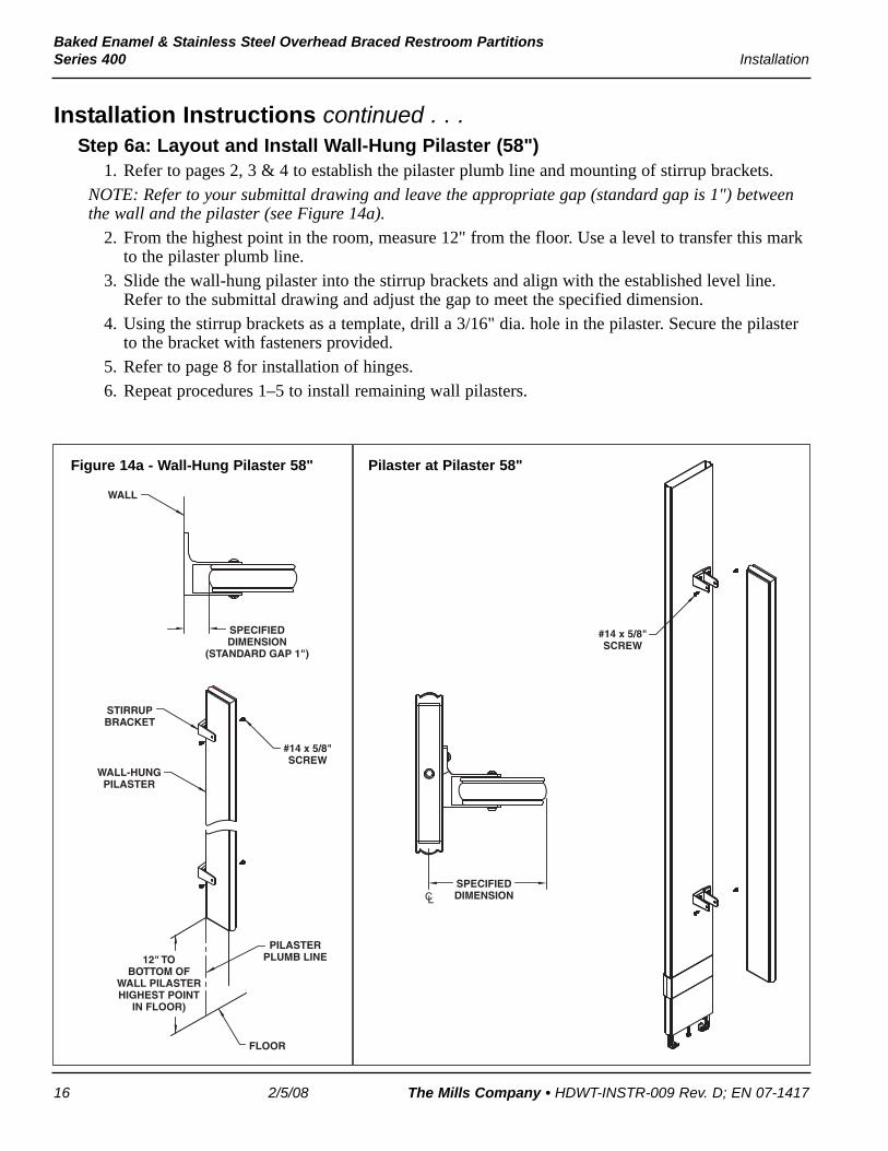
Installation Instructions continued . . .Step 6a: Layout and Install Wall-Hung Pilaster (58")
1. Refer to pages 2, 3 & 4 to establish the pilaster plumb line and mounting of stirrup brackets.NOTE: Refer to your submittal drawing and leave the appropriate gap (standard gap is 1") betweenthe wall and the pilaster (see Figure 14a).
2. From the highest point in the room, measure 12" from the floor. Use a level to transfer this markto the pilaster plumb line.
3. Slide the wall-hung pilaster into the stirrup brackets and align with the established level line.Refer to the submittal drawing and adjust the gap to meet the specified dimension.
4. Using the stirrup brackets as a template, drill a 3/16" dia. hole in the pilaster. Secure the pilasterto the bracket with fasteners provided.
5. Refer to page 8 for installation of hinges.6. Repeat procedures 1–5 to install remaining wall pilasters.
WALL-HUNGPILASTER
SPECIFIEDDIMENSION
(STANDARD GAP 1")
WALL
FLOOR
#14 x 5/8"SCREW
STIRRUPBRACKET
PILASTERPLUMB LINE12" TO
BOTTOM OFWALL PILASTERHIGHEST POINT
IN FLOOR)
Figure 14a - Wall-Hung Pilaster 58"
#14 x 5/8"SCREW
SPECIFIEDDIMENSIONCL
Pilaster at Pilaster 58"

17
Baked Enamel & Stainless Steel Overhead Braced Restroom PartitionsInstallation Series 400
The Mills Company • HDWT-INSTR-009 Rev. D; EN 07-1417 2/5/08
Installation Instructions continued . . .Step 6b: Layout and Install Wall-Hung Pilaster (69-9/16")
1. Refer to pages 2, 3 & 4 to establish the pilaster plumb line and mounting of wall brackets(stirrup).
NOTE: Refer to your submittal drawing and leave the appropriate gap (standard gap is 1") betweenthe wall and the pilaster.
2. Find the highest point in the room; measure 12" from the floor. Use a level to transfer this markto the pilaster plumb line.
3. Slide the wall-hung pilaster into the stirrup brackets and align with the established level line.Refer to the submittal drawing and adjust to meet the specified dimension.
4. Using the stirrup brackets as a template, drill a 3/16" dia. hole in the pilaster. Secure the pilasterto the bracket with fasteners provided.
5. Refer to page 7 for installation of headrail.6. Repeat procedures 1–5 to install remaining wall pilasters.
WALL-HUNGPILASTER
SPECIFIEDDIMENSION
(STANDARD GAP 1")
WALL
FLOOR
#14 x 5/8"SCREWSTIRRUP
BRACKET
PILASTERPLUMB LINE12" TO
BOTTOM OFWALL PILASTERHIGHEST POINT
IN FLOOR)
Figure 14b - Wall-Hung Pilaster 69-9/16"
#14 x 5/8"SCREW
SPECIFIEDDIMENSIONCL
Pilaster at Pilaster 69-9/16"

18
Baked Enamel & Stainless Steel Overhead Braced Restroom PartitionsSeries 400 Installation
2/5/08 The Mills Company • HDWT-INSTR-009 Rev. D; EN 07-1417
Installation Instructions continued . . .Step 7a: Install Continuous Stainless Steel Piano Hinge
NOTE: Before installing continuous piano hinges,make sure the door openings are the appropriatesize, all pilasters are plumb and that the headrail isinstalled. Refer to Figure 15a.
1. Use a 12" spacer to help support the weight ofthe door (refer to Figure 5a on page 6).
2. Determine the door swing by facing thecompartment from the outside. The Millssubmittal drawings will detail the actual doorswing. Hinge #HDWT-S0209 is for “left handin, right hand out” and hinge #HDWT-S0208is for “right hand in, left hand out.”
3. Place a door on the spacer and set the gap atthe latch side (standard gap is 3/16").
4. Center the hinge in the opening opposite thelatch and top to bottom on door(approximately 1/4" down from the top of thedoor).
5. Using the hinge as a template, drill a 1/4" dia.hole through the door at the top and bottomhole. Secure the hinge to the door withfasteners provided.
6. Ensure that the gap on the latch side isconsistent; repeat Procedure #5 on the pilasterside.
7. Drill a 1/4" dia. hole through the remaininghinge holes on the door and pilaster. Secure with fasteners provided.
8. Repeat Procedures 1-7 to install the remaining doors and hinges.9. Refer to page 10, Step 8a, to continue door latch and keeper installation.
#10-24 x 3/4"BARREL NUT
PILASTER
DOOR
CONTINUOUSSTAINLESS
STEELPIANO HINGE
HEADRAIL
#10-24 x 3/4"SHOULDER
SCREW
#10-24 x 1" SHOULDERSCREW
Figure 15a - Continuous Stainless SteelPiano Hinge

19
Baked Enamel & Stainless Steel Overhead Braced Restroom PartitionsInstallation Series 400
The Mills Company • HDWT-INSTR-009 Rev. D; EN 07-1417 2/5/08
Installation Instructions continued . . .Step 7b: Layout and Install Stainless Steel Flat Hinge
NOTE: Refer to Figure 15b when installing stainless steel flat hinges.1. Refer to pages 2 & 3 to establish the pilaster
plumb line.2. From the highest point in the room, measure
12" from the floor. Use a level to transfer thismark to the pilaster plumb line.
3. Carefully position the bottom of the bottomflat hinge on the established level line andcentered on the pilaster plumb line. Using theflat hinge as a template, mark the holelocations on the wall. Remove the flat hingeand drill a 1/4" dia. hole (minimum 2" deep) ateach hole location.
4. To locate the top flat hinge measure 56-3/8"from the bottom of the bottom flat hinge andplace a line on the pilaster plumb line.
5. Carefully position the top of the top flat hingeon the established level line and centered onthe pilaster plumb line, using the flat hinge asa template, mark the hole locations on thewall. Remove the flat hinge and drill a 1/4"dia. hole (minimum 2" deep) at each holelocation.
6. Insert plastic anchors and secure the flat hingeto the wall with fasteners provided.
7. To mount the door, refer to page 8, startingwith procedure #4.
8. Repeat procedures 1–6 to install remaining flathinges.
56-3/8"
PILASTERPLUMB LINE
TOP FLATHINGEPLASTIC
ANCHOR
#10 x 2"SCREW
BOTTOMFLAT HINGE
12" TO BOTTOMOF FLAT HINGE(HIGHEST POINT
IN FLOOR)
FLOOR
Figure 15b - Stainless Steel Flat Hinge

20
Baked Enamel & Stainless Steel Overhead Braced Restroom PartitionsSeries 400 Installation
2/5/08 The Mills Company • HDWT-INSTR-009 Rev. D; EN 07-1417
Installation Instructions continued . . .Step 8a: Surface-Mounted Latch & Strike/Keeper for Inswing Doors
NOTE: Refer to Figure 16a when installing inswing doors. ADA COMPLIANT DOORS: Wheninstalling coat hook, wall bumper and door pull, refer to Figure 16b for proper location.
1. Position the latch on the inside of the door, centered top to bottom on the 58" tall doors (41"above finished floor). The leading edge of the latch body should be 3/8" from the door edge.
2. Using the latch as a template, mark the hole locations on the door. Remove the latch and drill1/4" dia. holes through the door. Secure the latch to the door with fasteners provided.
3. With the door in the closed position, place the strike/keeper on the pilaster and align the top ofthe strike/keeper so it is 1/2" maximum above the bottom edge of the latch slide bar and fitswithin the top notch of the keeper.
4. Wrap Around Strike/Keeper Applications: Using the strike/keeper as a template, mark thehole locations on the pilasters. Remove the strike/keeper and drill 1/4" dia. holes through thepilaster. Secure to the pilaster with fasteners provided.Flat Strike/Keeper Applications: Using the flat strike/keeper as a template, mark the holelocations on the pilasters. Remove the strike/keeper and drill 1/8" dia. holes through one face ofthe pilaster only. Secure to the pilaster with fasteners provided.
Do not permit drill bit to touch outside face of pilaster.
5. Inswing ADA Doors: For 34" and 36" doors, drill a 1/4" dia. hole through the door. Mount thedoor pull to the inside of the door with fasteners provided.
NOTE: Local codes vary from state to state. Check your local codes before installing coat hook.
6. Install the coat hook on the inside of the door on the latch side at a location 3" down from thetop and 3" in from the side. Using the coat hook as a template, drill two 9/64" dia. pilot holesthrough one face of the door only. Secure the coat hook to the door using the fasteners provided.
Do not permit drill bit to touch outside face of door.
7. Repeat Procedures 1–6 for remaining doors.
#10-24 x 1-3/8"SHOULDER
SCREW
#10-24 x 3/4"BARREL NUT
#10-24 x 3/4"SHOULDER
SCREW
#10-24 x 1"SHOULDER
SCREW
OFDOOR
DOOR PULL (FOR 34" AND 36" DOORS)
SURFACE-MTD. LATCH
WRAP AROUND INSWING
STRIKE/KEEPER
OFDOOR
3/8"
1/2"
3"
3"
#10 x 3/4"FLAT HEAD
SHEET METALSCREW
FLAT INSWING STRIKE/KEEPER
#10 x 5/8"SHEET METAL
SCREW
COAT HOOK (INSWING)
OFDOOR
CL
CL
CL
SLIDE BAR
Figure 16a - Surface-Mounted Latch and Strike/Keeper for Inswing Doors

21
Baked Enamel & Stainless Steel Overhead Braced Restroom PartitionsInstallation Series 400
The Mills Company • HDWT-INSTR-009 Rev. D; EN 07-1417 2/5/08
Installation Instructions continued . . .Step 8b: Surface-Mounted Latch & Strike/Keeper for Outswing Doors
NOTE: Refer to the details in Figure 16b when installing outswing doors.1. Position the latch on the inside of the door, centered top to bottom on the 58" tall doors (41"
above finished floor). The leading edge of the latch body should be 1" from the door edge.2. Using the latch as a template, mark the hole locations on the door. Remove the latch and drill
1/4" dia. holes through the door. Secure the latch and door pull to the door with fastenersprovided.
3. With the door in the closed position, place the strike/keeper on the pilaster and align the top ofthe strike/keeper so it is 1/2" maximum above the bottom edge of the latch slide bar.
4. Wrap Around Strike/Keeper Applications: Using the strike/keeper as a template, mark thehole locations on the pilasters. Remove the strike/keeper and drill 1/4" dia. holes through thepilaster. Secure to the pilaster with fasteners provided.Flat Strike/Keeper Applications: Using the flat strike/keeper as a template, mark the holelocations on the pilasters. Remove the strike/keeper and drill 1/8" dia. holes through one face ofthe pilaster only. Secure to the pilaster with fasteners provided.
Do not permit drill bit to touch outside face of door/pilaster.5. Install the wall bumper on the outside of the door on the latch side at a location 3" up from the
bottom and 3" over from the side. Using the wall bumper as a template, drill two 9/64" dia. pilotholes through one face of the door only. Secure the wall bumper to the door using the fastenersprovided.
Do not permit drill bit to touch outside face of door/pilaster.NOTE: Local codes vary from state to state. Check your local codes before installing coat hook.
6. Using the coat hook as a template, drill two 3/16" dia. pilot holes through one face of the pilasteronly. Refer to Figure 16b for suggested location.
Do not permit drill bit to touch outside face of pilaster.7. Repeat Procedures 1–6 for remaining doors.
#10-24 x 1-3/8"SHOULDER
SCREW
#10-24 x 3/4"BARREL NUT
OFDOOR
DOORPULL
SURFACE-MTD. LATCH
WRAP AROUND OUTSWING
STRIKE/KEEPER
CL
SLIDE BAR
#10-24 x 1"SHOULDER
SCREW
OFDOOR
CL
1/2"
1"
#10 x 3/4"FLAT HEAD
SHEET METALSCREWFLAT OUTSWING
STRIKE/KEEPER
OFDOOR
CL
COAT HOOK (OUTSWING)
#14 x 5/8"SCREW
3"3"
#10 x 5/8"SHEET METAL
SCREW
WALL BUMPER(OUTSWING)
Figure 16b - Surface-Mounted Latch andStrike/Keeper for Outswing Doors

22
Baked Enamel & Stainless Steel Overhead Braced Restroom PartitionsSeries 400 Installation
2/5/08 The Mills Company • HDWT-INSTR-009 Rev. D; EN 07-1417
Installation Instructions continued . . .Step 9: Install Double Door Pull
NOTE: Refer to Figure 17a for doors with concealed latch, Figure 17b for doors with surface-mounted latch or Figure 17c for stainless steel door pull.
1. Using the door pull as a template, mark the location for the top hole on the inside of the door30-3/4" up from the bottom of 58" tall doors (42-3/4" above finished floor). The center of thedoor pull should be 4" (for concealed latch) or 5-1/2" (for surface-mounted latch) from the dooredge.
2. Drill 1/4" dia. holes through the door as shown. Secure the door pulls to the door with fastenersprovided.
3. Repeat procedures 1–2 to install remaining doors.NOTE: Local codes vary from state to state. Check your local codes before installing door pulls.
CONCEALEDLATCH
DOORPULL
DOOR PULL(COUNTERSINK)
#10-24 x 2"FLAT HEADMACHINESCREW
30-3/4"(BOTTOMOF DOOR)
42-3/4"A.F.F.
1/4" HOLES4"
Figure 17a - Concealed Latch
#10-24 x 2"FLAT HEADMACHINESCREW
SURFACE-MTD.LATCH
DOOR PULL(COUNTERSINK)
DOORPULL
5-1/2"
1/4" HOLES
30-3/4"(BOTTOMOF DOOR)
42-3/4"A.F.F.
3-1/2"(89mm)
Figure 17b - Surface-Mounted Latch
#10-24 x 1-3/8"SHOULDER
SCREWSLIDE LATCH
DOOR PULL(STAINLESS
STEEL)
DOOR PULL(STAINLESS
STEEL)
#10-24 x 1-3/8"SHOULDER
SCREW
Figure 17c - Double Door Pull (Stainless Steel)