implementing immediate forwarding for 4g in a network
TRANSCRIPT

Implementing immediateforwarding for 4G in a network
simulator
Magnus Vevik Austrheim
Thesis submitted for the degree ofMaster in Programming and Networks
60 credits
Department of InformaticsFaculty of mathematics and natural sciences
UNIVERSITY OF OSLO
Autumn 2018


Implementing immediateforwarding for 4G in a network
simulator
Magnus Vevik Austrheim

© 2018 Magnus Vevik Austrheim
Implementing immediate forwarding for 4G in a network simulator
http://www.duo.uio.no/
Printed: Reprosentralen, University of Oslo

Contents
1 Introduction 31.1 Hypothesis . . . . . . . . . . . . . . . . . . . . . . . . . . . . . 41.2 Experimental Approach . . . . . . . . . . . . . . . . . . . . . 51.3 Limitations . . . . . . . . . . . . . . . . . . . . . . . . . . . . . 51.4 Research Method . . . . . . . . . . . . . . . . . . . . . . . . . 61.5 Main Contributions . . . . . . . . . . . . . . . . . . . . . . . . 61.6 Outline . . . . . . . . . . . . . . . . . . . . . . . . . . . . . . . 7
2 Background 92.1 IP . . . . . . . . . . . . . . . . . . . . . . . . . . . . . . . . . . 92.2 TCP . . . . . . . . . . . . . . . . . . . . . . . . . . . . . . . . . 9
2.2.1 Congestion Control and Avoidance . . . . . . . . . . 102.2.2 Selective Acknowledgement (SACK) . . . . . . . . . . 112.2.3 Recent Acknowlegment (RACK) . . . . . . . . . . . . 12
2.3 Long Term Evolution (LTE) . . . . . . . . . . . . . . . . . . . 142.3.1 The need for LTE . . . . . . . . . . . . . . . . . . . . . 152.3.2 LTE Architecture . . . . . . . . . . . . . . . . . . . . . 172.3.3 LTE Air Interface . . . . . . . . . . . . . . . . . . . . . 19
2.4 LTE Radio Protocol Stack . . . . . . . . . . . . . . . . . . . . . 222.4.1 Packet Data Convergence (PDCP) . . . . . . . . . . . 222.4.2 Radio Link Control (RLC) . . . . . . . . . . . . . . . . 232.4.3 Medium Access Control (MAC) . . . . . . . . . . . . 262.4.4 Physical layer (PHY) . . . . . . . . . . . . . . . . . . . 29
2.5 Noise and Interference . . . . . . . . . . . . . . . . . . . . . . 302.5.1 Signal transmission and reception . . . . . . . . . . . 302.5.2 Modulation schemes . . . . . . . . . . . . . . . . . . . 322.5.3 Propagation . . . . . . . . . . . . . . . . . . . . . . . . 322.5.4 Fading . . . . . . . . . . . . . . . . . . . . . . . . . . . 332.5.5 Metrics . . . . . . . . . . . . . . . . . . . . . . . . . . . 33
3 Design 353.1 Hypothesis . . . . . . . . . . . . . . . . . . . . . . . . . . . . . 35
3.1.1 Throughput . . . . . . . . . . . . . . . . . . . . . . . . 353.1.2 Latency . . . . . . . . . . . . . . . . . . . . . . . . . . . 363.1.3 Applicability . . . . . . . . . . . . . . . . . . . . . . . 36
3.2 Related Works . . . . . . . . . . . . . . . . . . . . . . . . . . . 363.2.1 XLR8 . . . . . . . . . . . . . . . . . . . . . . . . . . . . 36
1

3.2.2 Improving TCP Performance Over Mobile Data Net-works . . . . . . . . . . . . . . . . . . . . . . . . . . . 37
3.2.3 Occupancy regulation for ARQ Re-ordering Buffer . 393.2.4 Limiting HARQ retransmissions in Downlink for
Poor Radio Link in LTE . . . . . . . . . . . . . . . . . 393.2.5 Advice to link designers on link Automatic Repeat
reQuest (ARQ) . . . . . . . . . . . . . . . . . . . . . . 403.3 Proposed Scheme . . . . . . . . . . . . . . . . . . . . . . . . . 40
3.3.1 Immediate Forwarding . . . . . . . . . . . . . . . . . 413.3.2 Threshold Tuning . . . . . . . . . . . . . . . . . . . . . 423.3.3 PDCP reordering . . . . . . . . . . . . . . . . . . . . . 433.3.4 RACK awareness . . . . . . . . . . . . . . . . . . . . . 44
4 Implementation 454.1 NS-3 . . . . . . . . . . . . . . . . . . . . . . . . . . . . . . . . . 45
4.1.1 LTE Module . . . . . . . . . . . . . . . . . . . . . . . . 454.1.2 DCE . . . . . . . . . . . . . . . . . . . . . . . . . . . . 50
4.2 Simulation Setup . . . . . . . . . . . . . . . . . . . . . . . . . 514.2.1 User Equipment node . . . . . . . . . . . . . . . . . . 514.2.2 Evolved NodeB node . . . . . . . . . . . . . . . . . . . 524.2.3 SGW/PGW node . . . . . . . . . . . . . . . . . . . . . 524.2.4 Remote host node . . . . . . . . . . . . . . . . . . . . . 524.2.5 Traces and Data Collection . . . . . . . . . . . . . . . 52
4.3 HARQ Re-transmission Limit . . . . . . . . . . . . . . . . . . 534.4 RLC AM Immediate Forwarding . . . . . . . . . . . . . . . . 53
4.4.1 Original implementation . . . . . . . . . . . . . . . . 534.4.2 Modification . . . . . . . . . . . . . . . . . . . . . . . . 544.4.3 Forward () . . . . . . . . . . . . . . . . . . . . . . . . . 58
4.5 TCP . . . . . . . . . . . . . . . . . . . . . . . . . . . . . . . . . 604.5.1 LibOS Modifications . . . . . . . . . . . . . . . . . . . 61
4.6 3GPP HTTP Applications . . . . . . . . . . . . . . . . . . . . 624.6.1 Server . . . . . . . . . . . . . . . . . . . . . . . . . . . 624.6.2 Client . . . . . . . . . . . . . . . . . . . . . . . . . . . . 64
5 Results 655.1 Experiment setup . . . . . . . . . . . . . . . . . . . . . . . . . 655.2 Short dynamic flows . . . . . . . . . . . . . . . . . . . . . . . 66
5.2.1 Good signal conditions . . . . . . . . . . . . . . . . . 665.2.2 Poor signal conditions . . . . . . . . . . . . . . . . . . 67
5.3 Long flows . . . . . . . . . . . . . . . . . . . . . . . . . . . . . 685.3.1 Poor signal conditions . . . . . . . . . . . . . . . . . . 68
5.4 Evaluation . . . . . . . . . . . . . . . . . . . . . . . . . . . . . 695.5 Limitations . . . . . . . . . . . . . . . . . . . . . . . . . . . . . 69
6 Conclusions 71
7 Future Work 73
2

Chapter 1
Introduction
As the world of networking continues to move towards wireless solutions,more and more challenges emerge as a result of using and patching upolder technologies that could not have anticipated either the scale orcircumstances of today’s realities in their design.
Mobile networks have specific challenges, particularly rapidly varyingbit rate and frequent high levels of transmission losses due to interferencein highly unpredictable signal conditions. Increasingly more mobilebandwidth is having less and less effect, because delay has become acritical factor limiting performance. Long Term Evolution (LTE) is astandard for high-speed wireless communications for mobile networks,more commonly marketed as 4G LTE, that addresses these challenges byproviding features such as lower data transfer latency and a simplifiedsystem architecture with better and more robust support for a large numberof users.
While there is still room for improvement and with 5G on the horizonfor the near future, the system architecture and procedures that mobilenetwork standards like LTE use to tackle its own problems can also imposeunderlying challenges for the network transport protocols that passes overthese mobile network systems. An essential attribute of the TranmissionControl Protocol (TCP) protocol, one of the most used protocols in digitalnetwork communications, is that its throughput performance relies on in-order delivery of its data packets to a significant extent. As frequentpacket losses and re-transmissions are in the nature of mobile networks,the current method of ensuring in-order delivery in respect to TCP is to usea buffer for storing packets until losses have been repaired, causing delay.With the rapid widespread deployment of TCP RACK (Linux, iOS andWindows), this main assumption of in-order buffering on which mobiledata networking was built can be reassessed to allow the opportunity toremove reordering delays and associated buffer memory.
In addition, there is thought that delay can be further reduced by usingtechnologies such as Active Queue Management (AQM) and ExcplicitCongestion Notification (ECN) to limit queuing delay in the networkelements.
3

Figure 1.1: Current solution to HoL blocking through buffering
1.1 Hypothesis
TCP RACK is a loss detection algorithm that, instead of counting sequencesof duplicate acknowledgements, uses the notion of time for repair of packetlosses. While the most common approach is to count three duplicate ac-knowledgements, RACK uses a time window of one-quarter of the RoundTrip Time (RTT), allowing out-of-order sequential reception. If any lostpackets do not arrive to fill the entire sequence by this time, the packet isdeemed lost. This radically alters a number of assumptions on which lowerlayer protocols have been designed.
One such assumption is found on the link-layer, where buffering is usedto make sure that data segments are sent in sequentially correct order in re-spect to loss detection algorithms at the transport-layer. This process ofreordering data segments causes Head-of-line blocking (HOL), illustratedin figure 1.1. This problem can induce delay, and is implemented with theassumption that the link must send the data in-order to upper-layer to workin conjunction with the assumed sequence based loss detection algorithms.
The hypothesis is that while using TCP RACK, the assumption thatthe link has to reorder data sequentially in the receive buffer can be rolledback. Instead, the link will send data segments out-of-order to bypass HOLblocking delay, and let the link resend any lost data segments in time to fillany gaps in the TCP receive window within one-quarter on the RTT. Theproposed change from the current schematic in figure 1.1 in illustrated infigure 1.2 below.
4

Figure 1.2: Proposal: Bypass HoL blocking with RACK
1.2 Experimental Approach
In order to test the proposed hypothesis, we need to simulate a mobile net-work with functionality that reaches the technological requirements andspecifications. Using the ns-3 network simulator, we can simulate the error-prone wireless environment, and modify the simulators open-source filesto implement the desired forwarding scheme.
This thesis aims to solve the following problems:
1. Investigate the potential for forwarding IP packets out-of-orderduring reorering procedures on the radio link layer, and furthermeasures to favor link-layer retransmissions.
2. Implement the desired scheme in a network simulator.
3. Simulate and compare the performance of a TCP Cubic flow usingthe default link reordering scheme versus forwarding packets out-of-order.
1.3 Limitations
The focus of this thesis is limited to a single TCP flow transversing thesimulated mobile network. While in reality such a flow would competewith other flows in terms of bandwidth and queueing, the performance ofsuch other flows using different protocols in the proposed modified schemeare not considered within the scope of this thesis.
The error models are limited to LTE induced errors, and assumed aperfect link from the end of the mobile network to the remote host. This
5
enhances the focus on the effect of radio spectrum errors, while limitingthe scope to not account for external transmission errors. To further thefocus on the proposed scheme, the TCP flow is limited to only transverseone radio link on the network path.
Certain aspects such as data collection, implementations of specifica-tions or Linux kernel version and protocol availability are to different de-grees limited to the current version of the ns-3 simulator and its subprojects.
It is also noted that the concept of randomness in regard to error modelsare limited to computed randomness variables that can never be trulyrandom and therefor not a perfect representation of random errors in thereal world.
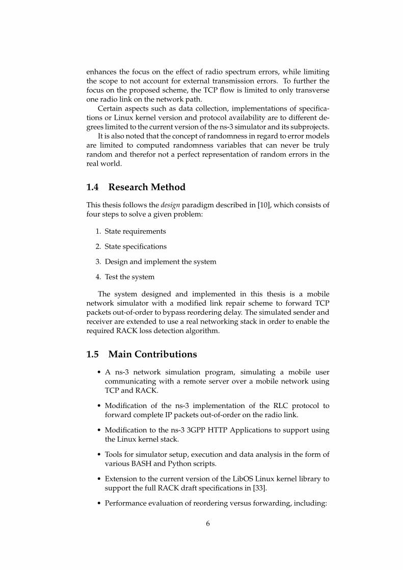
1.4 Research Method
This thesis follows the design paradigm described in [10], which consists offour steps to solve a given problem:
1. State requirements
2. State specifications
3. Design and implement the system
4. Test the system
The system designed and implemented in this thesis is a mobilenetwork simulator with a modified link repair scheme to forward TCPpackets out-of-order to bypass reordering delay. The simulated sender andreceiver are extended to use a real networking stack in order to enable therequired RACK loss detection algorithm.
1.5 Main Contributions
• A ns-3 network simulation program, simulating a mobile usercommunicating with a remote server over a mobile network usingTCP and RACK.
• Modification of the ns-3 implementation of the RLC protocol toforward complete IP packets out-of-order on the radio link.
• Modification to the ns-3 3GPP HTTP Applications to support usingthe Linux kernel stack.
• Tools for simulator setup, execution and data analysis in the form ofvarious BASH and Python scripts.
• Extension to the current version of the LibOS Linux kernel library tosupport the full RACK draft specifications in [33].
• Performance evaluation of reordering versus forwarding, including:
6

1.6 Outline
The thesis consists of the following parts:
• Chapter 2: an overview of the technological background relevant tothe thesis.
• Chapter 3: describes the design of the hypothesis.
• Chapter 4: breaks down the implementation of the design.
• Chapter 5: shows the simulation results and evaluation.
• Chapter 6: summerizes the work and draws the final conslusion.
• Chapter 7: lists the future work to build on this thesis.
7

8

Chapter 2
Background
Term DefinitionSegment Unit of data in the Transport layerPacket Unit of data in the Network layerFrame Unit of data in the Link layer
SDU Service Data Unit in the LTE Radio protocol stackPDU Protocol Data Unit in the LTE Radio protocol stack
Table 2.1: Cross-layer terminology used.
2.1 IP
The Internet Protocol (IP) is the principal protocol for networking, itspurpose is to relay packets through the network from the source to thedestination host. The protocol uses IP addresses to identify each host in thenetwork.
Internet Protocol version 4 (IPv4) is currently the most dominantprotocol in the internet. Its upgraded successor IPv6, which dealt withthe exhaustion of the IPv4 address space, is being deployed incrementallydeployed.
2.2 TCP
The Tranmission Control Protocol (TCP) protocol is a transport protocolused for communication between applications, it complements the IPprotocol and thus the suite as a whole is often also called TCP/IP. Itspurpose is to provide reliability of data transfer through ordering and errorchecking of packets.
File transferring, e-mail or browsing are examples of applications thatuses TCP for its reliability, re-transmitting any lost packets to ensure alldata is delivered. For purposes such as video streaming that is not as
9

dependent as much on reliability, User Datagram Protocol (UDP) is a fasteralternative.
In essence, a TCP works by the communicating parties acknowledgingsuccessfully transmitted packets. When a sender sends one or morepackets, the receiver must respond with an acknowledgement for eachpacket received. When the sender does not receive an acknowledgementfor a packet, it means that there is a hole in the transmission and the packetmust be re-transmitted.
2.2.1 Congestion Control and Avoidance
As a statefull connection communicating back and fourth, TCP has limitedthroughput as opposed to a stateless protocol like UDP which does notregard reliability. In order to utilise the available bandwidth, TCP wants tosend as many packets as possible for each iteration, without congesting thenetwork causing these packets to be lost. If there are buffers on the networkroute that are congested or does not have enough capacity to buffer a largenumber of TCP packets, the buffer will overflow and the packets will bedropped. In 1986, a congestion control algorithm was added to TCP toenforce conservation of sending packets.[32]
Congestion controls works by keeping a Congestion Window (CWND)variable at the sender which limits the amount of data TCP can send.[7]When initiating a flow, TCP enters slow-start, which starts by sending onepacket and then exponentially increase the number of packets per RoundTrip Time (RTT).[32] At the first sign on congestion, normally by packetloss, the CWND is reduced by half to compensate for the overshoot thatcaused congestion. Now that a reasonable CWND size is determined, TCPenters the state of congestion avoidance, conservatively probing for morebandwidth by gradually increasing the CWND until a congestion signal(packet loss) lowers it again. Some of these states are illustrated in figure2.1.
One form of congestion signal in TCP is by using timers, for example isa packet is not acknowledged before a timeout. Another congestion signalhighly relevant to this thesis is duplicate acknowledgements, or dup-acks.An acknowledgement is considered a duplicate when[7]:
• The acknowledgement number is equal to the greatest acknowledge-ment received on the given connection.
• The advertised window in the incoming acknowledgement equalsthe advertised window in the last incoming acknowledgement.
in addition to erroneous properties like outstanding/no data or SYNand FIN header bits being off.
Say by way of example a sender sends five packets in sequence, SN(1)through SN(5), but SN(2) is lost in transmission. The receiver receivesSN(1) and responds with ACK(1), now expecting SN(2) next. However,since SN(2) was lost the next two packets to be reveived are SN(3), SN(4)
10

Figure 2.1: Graph showing different TCP states over time, from [24].
and SN(5). Since these sequence numbers are greater than the expectedsequence number, the receiver will regard these ad dup-acks and respondwith ACK(1) for each of the last three packets to signal that SN(1) wasthe last packet that was received in-order. This will make the sendercount three dup-acks which is the standard threshold and trigger fast-retranmission, in which the sender performs a re-transmission of whatappears to be the missing segment, without waiting for the re-transmissiontimer to expire.[7] Different TCP algorithms have their own procedures forhandling congestion signals such as this, with the default being a state offast-recovery which waits for acknowledgement of the entire transmissionwindow.
The problem is that TCP cannot determine whether dup-acks arecaused by actual congestion or packet disordering.
2.2.2 Selective Acknowledgement (SACK)
Selective Acknowledgement (SACK) is an optional elements for TCP thatappends additional information to the otherwise ambiguous dup-ACK.The limited information provided by dup-ACKs means a TCP sender canonly learn about a single lost packet per round trip time.[20] As a result,other packets may end up being transmitted multiple times. If both endsystems support and enable the SACK option, each acknowledgement willinclude a range of non-contiguous packets received. Figure 2.2 illustratesan example similar to the previous one, where SN(2) is lost, but with SACKinforming which packets have been received out of order. This allows thesender to re-transmit only SN(2) knowing the following sequence numbershave been delivered, where otherwise it could not have know and wouldhave to send all packets starting from SN(2) again.
11

Figure 2.2: Illustration of a TCP connection using SACK.[29]
DSACK is an extension to the SACK specification that enabled TCP toreport duplicate segments, which is otherwise not specified in the RFC.[19]
2.2.3 Recent Acknowlegment (RACK)
Recent Acknowlegment (RACK)[8] is a sender-only TCP loss detection al-gorithm developed by Google, which uses the notion of time instead of theconventional packet or sequence counts to detect losses for modern TCPimplementations. It supports per-packet timestamps and the Selective Ac-knowledgement (SACK) option. It is intended to replace the conventionaldup-ACK threshold approach and its variants.
RACK is designed to, among other things, combat three common lossand reordering patterns that has been observed in today’s Internet:
1. Lost re-transmissions. Traffic policers and burst losses often causere-transmissions to be lost again, severely increasing TCP latency.
2. Tail drops. Structured request-response traffic turns more losses intotail drops. In such cases, TCP is application-limited, so it cannot sendnew data to probe losses and has to rely on a Retransmission Timeout(RTO).
3. Reordering. Link layer protocols or routers’ internal load-balancing
12

can deliver TCP/IP packets out-of-order. The degree of suchreordering is usually within the order of the path round trip time.
RACK timestamps all transmitted and re-transmitted packets. It alsokeeps a reordering window and a minimum RTT value which are calculatedbased on the packet relative timestamps. When a packet is received outof order, the packets sent chronologically before that were either lost orreordered. In this case, RACK conducts time-based inferences insteadof inferring losses with packet or sequence counting approaches like thestandard TCP loss recovery mechanism[7] or Forward Acknowledgment(FACK)[21]. Today’s prevalent reordering patterns and lost retransmis-sions are making packet-counting approached more and more unreliable.Maintaining a duplicate threshold can be difficult as it needs to be con-stantly adjusted to allow big packets bursts and low enough to detect realpacket losses all using sequence space logic. Higher speed links and fastertechnology in the Internet are also problematic for sequence counting, asrapid volleys of packets can hit the DupThresh fast when there are gaps inthe sequence due to loss or reordering.
Where a DupThresh approach would deem a packet lost at for instancethree duplicate acknowledgements, RACK deems a packet lost if somepacket sent sufficiently later has been (S)ACKed. ’Sufficiently later’ is laterby one reordering window, for which the default is set to one quarter ofa Round Trip Time, min_rtt / 4, for which the minimum RTT is calculatedper packet acknowledgement. As of draft 01, the default is an algorithmthat adapts the reordering window to the reordering degree, but the draftused in this thesis uses on quarter of the minimum RTT. For packets thatare reordered in the network, there is no need to initiate re-transmission ifthe packets eventually arrive within the reordering window. The choice forusing one quarter of minimum RTT is because Linux TCP uses the samefactor in its implementation to delay early re-transmit to reduce spuriousloss detection in the prescience of reordering, in addition to that the authorsclaim through experience that this works reasonably well.[8]
Say by way of example you want to transmit three packets SN(1), SN(2)and SN(3), but reordering on the network path causes SN(3) to be deliveredfirst. If SN(1) and SN(2) arrive within min_rtt / 4 to fill the reordering win-dow, they are not deemed lost. If they do however arrive ’sufficiently later’after SN(3), they will be falsely deemed lost and initiate fast re-transmit.
While allowing a small degree of reordering is one of the keyinnovations of RACK. It also has an advantage in being able to detectlosses of retransmissions that the conventional dup-ACK approaches donot when there is an insufficient number of dup-ACKs to trigger fastretransmission. Take SN(1), SN(2) and SN(3) again, this time the firsttwo are actually lost and SN(3) arrives. The receiver sends back aSACK notifying the sender that SN(1) and SN(2) are missing, RACK theneventually deems these lost and re-transmits them as R(1) R(2). Now re-
13

transmission R(1) is lost again but R(2) arrives and is SACKed, RACK yetagain deems R(1) lost and re-transmits it again. Such lost retransmissionsare common with low rate limits.
Tail Loss Probe
In the world of congestion control, the worst case scenario is an RTOwhich induces seconds of delay. While this can be avoided using the re-transmission schemes previously presented, they rely on acknowledge-ments of subsequent packets to investigate packet losses. This introducesan important edge case, tail loss. When the tail (last few packets) of a trans-mission is lost, there is not enough subsequent acknowledgements to indi-cate a loss, which will lead to an RTO timeout. Tail Loss Probe (TLP)[12]is a sender-only algorithm that allows the transport to recover tail lossesthrough fast recovery as opposed to lengthy re-transmission timeouts. TLPworks by repeating the last unacknowledged data segment (probe) withan aggressive timer in order to force some feedback from the receiver. If atail segment was lost, the probe will feed back an acknowledgement to thesender to signal that the tail segment was lost and allowing fast recoveryinstead of an RTO timeout. An example is illustrated in figure 2.3.
TLP is a supplemental algorithm but works naturally well with RACKto further reduce RTO recoveries. TLP gives RACK additional (S)ACKs todetect losses and in turn RACK relaxes TLP’s requirement for using FACKand re-transmitting the highest sequence packet.[8] Given the dramaticdelay from an RTO, good use of TLP is important. According to theTLP specification[12]: measurements on Google Web servers show thatapproximately 70% of retransmissions for Web transfers are sent after theRTO timer expires, while only 30% are handled by fast recovery.
2.3 Long Term Evolution (LTE)
Long Term Evolution (LTE) is a standard for mobile broadband networksfor mobile devices and terminals, developed by the Third GenerationPartnership Project (3GPP). LTE evolved from the previous mobile networkarchitecture 3rd Generation (3G). The terms 4G and LTE are ofteninterchanged and can be a cause for confusion. The InternationalTelecommunication Union (ITU) intended for the term 4th Generation(4G) to be used for system that meet certain requirements like peakdownload speeds achieved in different environments etc, using their ownIMT-Advanced to model the target requirements. LTE did not meet theserequirements initially, and the engineering community came to describe itas 3.9G.[11] Needless to say, this did not stop the markets from labellingLTE as a 4G technology, and eventually the ITU gave in, allowing LTE tobe described as a true 4th Generation (4G) technology.
14

Figure 2.3: RACK + TLP timeline from [9]
2.3.1 The need for LTE
There were various motivations for evolving the revolutionary and dom-inant 3G system, such as latency issues and giving designers a fresh startfrom complex 3G specifications as a result of keeping backward compati-bility support for earlier devices.[11]
The leading motivation however that pushed the need for LTE was thegrowth of mobile data. For many years, voice calls dominated the trafficin mobile telecommunication networks. The growth of mobile data wasinitially slow, but in the years leading up to 2010 its use started to increasedramatically.[11] 2.4 shows how the increase in mobile data usage went toovertake the more stable voice usage.
In the older systems like Global System for Mobile Communications(GSM), voice calls were highly prioritises in the design ans data serviceswere only possible over the circuit switched connection, yielding very lowdata rates. Later the Universal Mobile Telecommunication System (UMTS)went to improve the data rates by emulating a circuit switched connectionfor real time services and a packet switched connection for datacomservices in the access network, but data packets still relied upon the circuitswitched core in the form of allocating IP addresses from establishment andrelease of data services.[22]
The LTE specifications by the 3GPP describes an evolved design ofthe older GSM and UMTS systems into a system optimised for packetswitching with lower complexity and higher data rates whilst ensure thecontinuity of competitiveness of the 3G system for the future.[22]
15

Figure 2.4: Worldwide mobile network traffic and data 2007-2011.[13]
16

Figure 2.5: Architecture of the evolved UMTS terrestrial radio accessnetwork. [11]
2.3.2 LTE Architecture
There are three main components of the LTE architecture, the User Equip-ment (UE), the uetran and the epc, each containing its own architecturewithin to fulfil their purpose.
UE
The UE depicts the device that is communicating through the LTE mobilenetwork. It is typically illustrated as a mobile phone, which easily conveysthe aspect of mobility and hardware limitations of a UE. In order tocommunicate with the mobile network, the UE uses the radio link, orwireless transmissions, that are in range of a radio base station that servesas a component of the next LTE component, the E-UTRAN.
E-UTRAN
The Evolved Universal Terrestrial Access Network (E-UTRAN) handlesradio communications between the UE and the EPC and just has onecomponent, the Evolved NodeB (eNB), which is the radio base station.Multiple EPCs are used to extend coverage, and the UE only communicateswith one eNB at the time, then being the serving eNB. If the E-UTRANcontains more than one eNB base station, the base stations can beinterconnected through the optional X2 interface. When a UE moves outof range of one base station into the range of another, a process calledhandover, the base stations can organise via the X2 interface to move theuser session between the two base stations. The data packets are sent fromthe eNBs to the EPC via the S1 interface.
17

Figure 2.6: Evolution of the system architecture from GSM and UMTS toLTE. [11]
EPC
The Evolved Packet Core (EPC) is the last main component of acrshort-lte, where data packets coming over the S1 interface from the E-UTRANis routed to the end of the LTE network and towards the destination endsystem. The EPC broke free from the circuit switching ways of its prede-cessors, and is purely based on the IP transport protocol for both real-timeand data services. A big factor that allowed the circuit switching core to bereplaced was Voice over IP (VoIP) which proved a reliable alternative forreal-time voice communications over a packet switched network.
Within the EPC there are again three main components, the MobilityManagement Entity (MME), the Serving Gateway (S-GW) and the PacketData Network (PDN) gateway (P-GW). The S1 link from the E-UTRANis split using two logical links, the S1-U for traffic going to the gatewayand S1-MME for signalling messages. The S-GW gateway acts as a router,forwarding traffic fro the base stations to the P-GW via the S5/S8 interface.The P-GW acts as the end point of the LTE network, connecting with theinternet using its SGi interface. The MME handles high-level operationssuch as security issues or unrelated data streams. The MME only usessignalling to manage its network elements.
18

Figure 2.7: Main components of the EPC.[11]
2.3.3 LTE Air Interface
The OSI model standardises communication functions into layers, where(logically) data flows down through the layers, and each layer is responsi-ble for communicating with its corresponding layer on the receiving side.For example application that wants to send a data to a destination host,will send the data to the Transport layer where transport protocols such asTCP or UDP are used to determine in what fashion the two parts shouldcommunicate. Down towards the lower layers the Network layer handleswhere the data should be sent or routed through the IP protocol, and theLink layer and Physical layer undertake the physical addressing and actualbit transmissions of the data.
In LTE Air Interface the physical and data link layers, also referredto as layers 1 and 2 respectively, are different from those of their wiredcounterparts. Layer 1 (PHY) divides data bulks up in smaller pieces that ismore manageable and safer to transmit over a wireless radio link, and layer2 controls these low-level operations and offers functionality to resolvetransmission errors before data is forwarded to the Network layer. Also,in the higher layers before entering layer 2 of the air interface, there is aseparation between the user plane and the control plane. The user plane iswhere the actually data flows as in the OSI model described above, whereasthe control plane handles control signals used to manage the users sessionwith its serving base station in the LTE network. Altogether the layersmake up the Air Interface Protocol Stack, illustrated in 2.9, while layers 1and 2 alone is referred to as the LTE Radio Protocol Stack.
LTE Channels
Data going through the LTE air interface may be grouped into differentchannels, namely the Physical channels, Logical channels or the Transport chan-
19

Physical channelsPhysical Uplink Shared Channel (PUSCH) Uplink data transfer.Physical Downlink Shared Channel (PDSCH) Downlink data transfer.Physical Uplink Control Channel (PUCCH) Uplink control signals.Physical Downlink Control Channel (PDCCH) Downlink control signals.Transport channelsUplink Shared Channel (UL-SCH) Uplink data transfer.Downlink Shared Channel (DL-SCH) Downlink data transfer.Logical channelsDedicated Traffic Channel (DTCH) Transmission of user data.Paging Control Channel (PCCH) Paging information.Broadcast Control Channel (BCCH) Broadcats system information to users.Dedcated Control Channel (DCCH) User specific information.Common Control Channel (CCCH) Setting up new connections.
Figure 2.8: Main LTE channels.
nels. These channels are required to segregate different sorts of data in anorganised manner. The various channels types of each of these groups areagain sorted into categories of down link and up link, as well as broadcast-ing, multi-casting, paging etc.
The physical channels are the main transmission channels that handlesuser data and control signals, while the transport and logical channels areused within the layer 2 protocols. For example when the RLC protocol hasdata to send, it passes the data down to the MAC layer on a logical channel.The MAC then sends this data as a transport block on a transport channelto physical layer, which in turn encodes this data to signals and transmitsthis data on a physical channel. The location of these channel groups arepinpointed in figure 2.9.
Table 2.8 lists some of the most commonly referred to channels:
Radio Resource Control (RRC)
The RRC protocol is used by the UE and eNB as part of the control plane inthe air interface. The RRC manages different states of a connecting such asbeing idle, connected or during handover, and configures the lower layersaccordingly using control signals. Functions include mobility, configura-tion of point to point radio bearers and broadcasting system information tohigher control plane protocols that handle functions such as authentication.While the RRC is mostly impartial regarding the data plane, it’s Quality ofService (QoS) functions does affect resource scheduling on lower layers.
20

Figure 2.9: Architecture of the air interface protocol stack.[11]
21

Figure 2.10: Data flow through the LTE radio protocol layers, from[31]
2.4 LTE Radio Protocol Stack
Both user data coming from the user plane and control signals from theRadio Resource Control (RRC) on the control plane pass through theentire Radio Protocol Stack. The relevant functions of each the PacketData Convergence (PDCP), Radio Link Control (RLC), Medium AccessControl (MAC) and Physical layer are described below in order. Note thattransmitting in the context of all but the physical layers means to submit thedata to lower layers.
When data moves down the layers, each non-physical layer addsits own header segment to the data in order to communicate with thecorresponding layer on the receiving side. A data packet that is receivedfrom a higher layer is call a Service Data Unit (SDU), whereas when it hasadded its own header to the SDU(s) it is called a Protocol Data Unit (PDU),which is sent toward lower layers. The flow of data units through the LTEradio protocol stack is illustrated in figure 2.10.
2.4.1 Packet Data Convergence (PDCP)
The Packet Data Convergence (PDCP) protocol ensures that handoverprocedure is relatively seamless by preventing packet loss by sendingstatus reports between the old and new eNB. The PDCP layer makes surethat packets pending transmission in one cell to terminal connection, are
22
transmitted in the new cell to terminal connection. This way all packetswill be ensured to be delivered to the endpoint.[15]
PDCP also ensures that all packets are delivered in order up to higherlayers.[15]
Header Compression
Sending data over the air interface can be expensive in terms of time andresources, so it is desirable to not send more then necessary. Large headersizes can become a problem when reaching the PDCP layer, especiallywhen considering the large 128 bit address spaces for IPv6, and whenattached to each data packet the transmission of headers across becomea significant portion of the radio link bandwidth. To combat this, the PDCPprotocol takes use of the RObust Header Compression (ROHC)[27]. Inessence, ROHC sends the full header on the first transmitted packet, butthen only sends any differences in the header for later packets. This greatlyreduces the overall overhead of the user data.
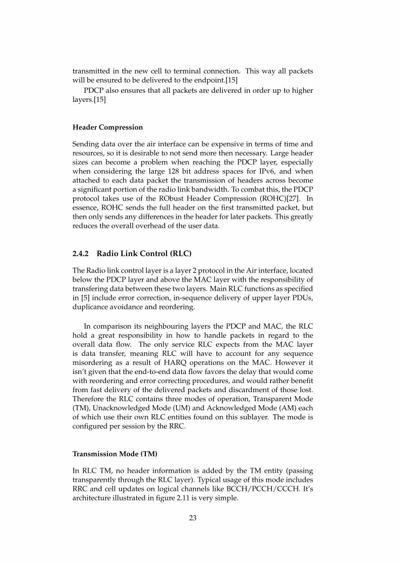
2.4.2 Radio Link Control (RLC)
The Radio link control layer is a layer 2 protocol in the Air interface, locatedbelow the PDCP layer and above the MAC layer with the responsibility oftransfering data between these two layers. Main RLC functions as specifiedin [5] include error correction, in-sequence delivery of upper layer PDUs,duplicance avoidance and reordering.
In comparison its neighbouring layers the PDCP and MAC, the RLChold a great responsibility in how to handle packets in regard to theoverall data flow. The only service RLC expects from the MAC layeris data transfer, meaning RLC will have to account for any sequencemisordering as a result of HARQ operations on the MAC. However itisn’t given that the end-to-end data flow favors the delay that would comewith reordering and error correcting procedures, and would rather benefitfrom fast delivery of the delivered packets and discardment of those lost.Therefore the RLC contains three modes of operation, Transparent Mode(TM), Unacknowledged Mode (UM) and Acknowledged Mode (AM) eachof which use their own RLC entities found on this sublayer. The mode isconfigured per session by the RRC.
Transmission Mode (TM)
In RLC TM, no header information is added by the TM entity (passingtransparently through the RLC layer). Typical usage of this mode includesRRC and cell updates on logical channels like BCCH/PCCH/CCCH. It’sarchitecture illustrated in figure 2.11 is very simple.
23

Figure 2.11: Transmission Mode (TM) architecture, from [11]
Figure 2.12: Unacknowledged Mode (UM) architecture, from [11]
Unacknowledged Mode (UM)
RLC UM is the most simplistic of the two data transfer modes. Itsarchitecture illustrated in 2.12 shows the three main functions enabledon this mode for both the transmitting and receiving entity. PDCPPDUs coming from the PDCP are put in a transmission buffer. The RLCcommunicated with the MAC layer through control signals and waits forthe MAC to report a transmisson opportunity on the link large enough tosend either one, multiple or segmented RLC SDUs. When such a payloadis prepared the RLC header is added to make a RLC PDU and is sent to thelink. On the receiver the RLC may recieve these RLC PDUs out of order dueto the Hybrid-Automatic Repeat Request (HARQ) retransmission schemeon the link. Since the RLC needs to deliver the received RLC SDUs in orderto the PDCP, the received data units are buffered and reordered before theyare stripped of their RLC headers and possibly re-assembled if they aresegmented.
Acknowledged Mode (AM)
RLC AM implements the same functions as RLC UM but with much moreextended functionality. While RLC UM does reorder out-of-order PDUs
24

Figure 2.13: Acknowledged Mode (AM) architecture, from [11]
received from the MAC it does not account for lost PDUs. The RLC AMmode provides reliability by accounting for such losses by implementingAutomatic Repeat Request (ARQ) functionality to signal the transmittingRLC AM entity that lost PDUs should be retransmitted. In order to frontthe communication between the RLC AM transmitting and receiving entity,RLC AM differentiates between data and control PDUs through setting adedicated bit in the RLC header. Data PDUs are handled as normal whilecontrol PDUs are used for internal information. An RLC AM entity can re-quest a stats PDU (type of control PDU) from the entity it is communicatingwith by setting a polling bit in the header, which is done at regular intervals,also called polling. The architecture of RLC AM is illustrated in figure 2.13.In addition to the tranmission buffer, the RLC AM contains a re-transmitbuffer, where copies of transmitted PDUs are temporarily stored. If a con-trol PDU signals that a data PDU must be retransmitted, it is extracted fromthe retransmission buffer.
For applications using TCP for purposes like emails or web browsing,RLC AM is desireable for the robustness and reliability provided by theARQ function. However this induces delay from the control overhad asopposed to cutting your losses. For applications like video streaming orvoice using protocols like VoIP or UDP, RLC UM is much more desireablefor such RTT sensitive flows that would rather skip the ARQ.
RLC Automatic Repeat Request (ARQ)
The RLC ARQ uses much overhead from the control signaling as opposedto other ARQs, but the principle of the error correcting scheme remains
25

the same. The RLC ARQ is a case of a selective repeat ARQ, meaning thatlost frames will be selectively NACKed so that the transmitted only needsto retransmit the selected ones as opposed to ARQ instances like Go-Back-N or Stop-and-Wait where the transmitter needs to retransmit all frameshigher than the one that was last acknowledged. This is very similar toTCP retranasmissions using Selective Acknowledgement (SACK) versuscumulative acknowledgements.
As an example, a transmitting RLC AM entity has a sending windowof five and sends data PDUs with SN(1) to SN(5). Out of these five SN(3)and SN(4) are lost in transmission, the receiving RLC AM entity acknowl-edged the highest SN(5) but also sends a NACK for SN(3) and SN(4). Thetranmitter advances the sending window by two since it know SN(1) andSN(2) were delivered, then retransmits SN(3) and SN(4) along with newPDUs SN(6) and SN(7) since the window advanced.
One might wonder why HARQ reordering is done on the RLC layer andnot on the MAC layer itself. This is a key feature of the Evolved UniversalTerrestrial Access Network (E-UTRAN) architecture in LTE, in UniversalTerrestrial Access Network (UTRAN) reordering is done on the MAC layer.The disadvantage of reordering on the MAC is additional buffering ofpackets. Since the RLC already keeps track of sequence numbering anduses transmission buffers, offloading such buffering from the MAC to theRLC reduces the overall architecture complexity.
Segmentation and Concatenation
Complete PDCP PDUs in the transmission buffer go through the processof segmentation or concatination if necessary before being transmitted.Higher layer data unites such as IP packets and PDCP PDUs maintainsa "static" size of one packet per data unit, whereas the RLC is at themercy of link layer transmission opportunities in addition to the size ofthe PDCP PDUs. When the quality of the radio link is good, there arelarge transmission opportunities from the MAC and the RLC can sendmultiple RLC SDUs and does so by concatenating them together into oneRLC PDU. When the quality of the radio link is poor, the transmissionopportunities may be smaller than the size of a PDCP PDU, and the RLCneeds to segment the RLC SDUs into incomplete segments and transmitthem, needing the receiver to re-assemble the segments back to a completeSDU. This is illustrated in figure 2.10 from the previous section.
2.4.3 Medium Access Control (MAC)
The Medium Access Control (MAC) protocol, specified by the 3GPP in[3], schedules transmissions that are carried out on the air interface andcontrols the low-level operation of the physical layer.[11] Data is receivedfrom the RLC layers in the form of MAC SDUs. These data unitscan then be combined through multiplexing and reassembled throughdemultiplexing, similar to the segmentation and concatination process
26

on the RLC. Important features of the MAC layers include buffer statusreporting, multiplexing/demultiplexing of data units and transmissionscheduling.
Buffer Status
The MAC layers on an UE device needs to inform the base station of howmuch data is available for transmission. It does so by sending a buffer statusreport of the current state of the transmission buffers. This is done bothperiodically, and for cases regarding the transmission buffers. A statusreport is sent if new data becomes ready for transmission, a higher prioritychannel has new data to send or for timeouts for pending transmissions.
Multiplexing and Demultiplexing
In similar fashion to the other layers, the MAC takes one or more RLCPDUs as MAC SDUs and appends its header to make a MAC PDU fortransmission, displayed in figure 2.10. In addition to the MAC SDUs thepayload contains control elements, such as buffer status report, powersignals, timing advances etc. The MAC protocol data unit differs from thatof the other layer in that the payload may contain padding at the end, inorder to round the size of the data unit up to the current Transport Block(TB) size. In addition each SDU in the payload is assigned its own headerthat hold information of the logical channel the SDU originated from andthe its size.
Scheduling
The MAC uses a scheduling algorithm, for which there are many differ-ent versions, to distribute the resources among the users. A base stationMAC scheduler needs to gather information about its UEs like buffer sta-tus reports and Quality of Service (QoS) to decide how to distribute re-source allocation. There is scheduling for uplink and downlink, where bothoutput values like transport block sizes permitted to UEs and modulationschemes. MAC SDU sizes are calculated on the downlink scheduling.
Different MAC scheduling algorithms vary between acheived through-put and fairness.[11] A high throughput scheduler will allocate resourcesto UEs with high signal-to-noise ratios to allows them to utilize the high-est data rates, maximizing cell throughput but aldo proves highly unfairto UEs experiencing poor signal conditions. Schedulers aiming for fairnesssuch as a round-robin approach giveas each UE the same data rate, beingvery fair but very inefficient in terms of cell throughput. Other algorithmsattempt to find a balance point inbetween these two extremes.
Hybrid-Automatic Repeat Request
The MAC performs error correction on the link, and does so very efficientlythrough the Hybrid-Automatic Repeat Request (HARQ) mechanism. The
27

following describes the HARQ operation and the concepts around it.
HARQ is a technique which combines features from Forward Error Cor-rection (FEC) and Automatic Repeat Request (ARQ) [17]. FEC adds a codeword to the data. The code word is larger than the actual data, and the twoare intertwined in such a way that even when it arrives at the receiver witherrors the receiver is still able to extract the actual data from it. A modu-lation scheme is needed to decide the comparative size of the code wordto the data, which makes an important tradeoff between throughput anderror management. Adding more bits for error checking reduced the avail-able bandwith for the actual data but provides greated error correction,and less bits for error checking gives more data bandwidth but reducesthe probability of correcting errors. Error management in ARQ checks forerrors but without the means to fix them. The ARQ takes the data andcomputes a Cyclic Redundancy Check (CRC), a bit sequence based on thedata it was computed from. The CRC is attached to the data and transmit-ted. At the receiver, the receiver calculates a CRC from the transmitted dataand compares it with the attached CRC. If any of the CRC bits are differ-ent, the transmission has errors and a retransmission is requested. TODO:UM vs AM "In HARQ, the actual data is encrypted with a FEC code, andparity bits are sent upon request or immediately sent along with the mes-sage when erroneous data is detected" [17]. In other words, HARQ detectserros upon reception, identifies which parts of the data was erroneous andretransmits only these missing bits instead of retransmitting the messageas a whole.
The HARQ operation is either synchronous or asyncrhonous. Syn-chronous HARQ processes retransmissions periodically over a certain timeinterval. Asynchronous HARQ retransmissions have no timing constraintsand are triggered via explicit signaling, giving better scheduling flexibilityat the expense of increased overhead due to signaling. HARQ can alsobe either adaptive or non-apaptive. Adaptive HARQ dynamically adjustsscheduling parameters such as code rate or resource allocation, allowingthe scheduler to properly adapt to the state of the radio link but again atthe expense of information overhead. Non-adaptive HARQ uses fixed sizesand formats, having less overhead but may be sub-optimal for schedul-ing. When the HARQ receives erronous data, the valid bits of the dataare buffered until the parity bits are retransmitted to be combined withthe buffered data. Chase combining is a type that uses less error-correctingcoding, correcting errors for good signal conditions, but in poor signalconditions there are not enough error-correcting bits to repair the errorsand a retransmission is requested. Incremental redundancy uses more error-correcting bits, but each retransmission contains multiple sets of code bitsfrom the same data bits, using different redundancy versions of the sets.This makes it sufficent for the receiver to repair losses and retransmissionsare only made in poor signal conditions and if the data was not decodedcorrectly.
28
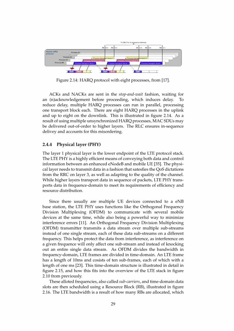
Figure 2.14: HARQ protocol with eight processes, from [17].
ACKs and NACKs are sent in the stop-and-wait fashion, waiting foran (n)acknowledgement before proceeding, which induces delay. Toreduce delay, multiple HARQ processes can run in parallel, processingone transport block each. There are eight HARQ processes in the uplinkand up to eight on the downlink. This is illustrated in figure 2.14. As aresult of using multiple unsynchronized HARQ processes, MAC SDUs maybe delivered out-of-order to higher layers. The RLC ensures in-sequencedelivey and accounts for this misordering.
2.4.4 Physical layer (PHY)
The layer 1 physical layer is the lower endpoint of the LTE protocol stack.The LTE PHY is a highly efficient means of conveying both data and controlinformation between an enhanced eNodeB and mobile UE [35]. The physi-cal layer needs to transmit data in a fashion that satesfies the QoS dictationsfrom the RRC on layer 3, as well as adapting to the quality of the channel.While higher layers transport data in sequence of packets, LTE PHY trans-ports data in frequence-domain to meet its requirements of efficiency andresource distribution.
Since there usually are multiple UE devices connected to a eNBbase station, the LTE PHY uses functions like the Orthogonal FrequencyDivision Multiplexing (OFDM) to communicate with several mobiledevices at the same time, while also being a powerful way to minimizeinterference errors [11]. An Orthogonal Frequency Division Multiplexing(OFDM) transmitter transmits a data stream over multiple sub-streamsinstead of one single stream, each of these data sub-streams on a differentfrequency. This helps protect the data from interference, as interference ona given frequence will only affect one sub-stream and instead of knockingout an entire single data stream. As OFDM divides the bandwidth infrequency-domain, LTE frames are divided in time-domain. An LTE framehas a length of 10ms and cosists of ten sub-frames, each of which with alength of one ms [23]. This time-domain structure is illustrated in detail infigure 2.15, and how this fits into the overview of the LTE stack in figure2.10 from previously.
These alloted frequencies, also called sub-carriers, and time-domain dataslots are then scheduled using a Resource Block (RB), illustrated in figure2.16. The LTE bandwidth is a result of how many RBs are allocated, which
29

Figure 2.15: LTE frame structure, from [23]
can be up to 100 RBs.
2.5 Noise and Interference
Digital transmission over a wireless medium are prone to variable and of-ten intense error rates and delay. From the source of the transmission an-tenna and towards the destination receiver, signals are exposed to externalinterference that can obstruct the encoded information. Atmospheric con-ditions such as noise on the transmission channel or factors like path prop-agation and fading due to large distances and blocking objects can causesevere error rates for wireless links. While technologies like Wireless LocalArea Networks (WLAN) are susceptible to wireless induces errors, LTE andSatellite are even more affected given the scale of factors such as distanceand mobility changes. Following are some of the key generic characteristicsof wireless systems.
2.5.1 Signal transmission and reception
The data in need of transmission are represented by bits. On the physicallayer these bits are encoded by a modulator into a radio wave signals. Thisis done by computing the bits into symbols that represent the amplitude andphase of the radio wave. On the receiver, the radio wave is picked up byan analogue antenna and the symbol are extracted from the amplitude andphase of the radio wave. However during symbol extraction it isn’t giventhat the radio wave hasn’t been tampered with by noise of interference. Fordistorted waves, the intended symbol may not be clear given the amplitudeand phase. With variable levels of confidence the receiver will have todecide whether the symbol might be a 0 bit or a 1 bit. For heavy noiseand interference, the receiver might misinterpret a 0 bit for a 1 bit or viceversa, causing errors.
30
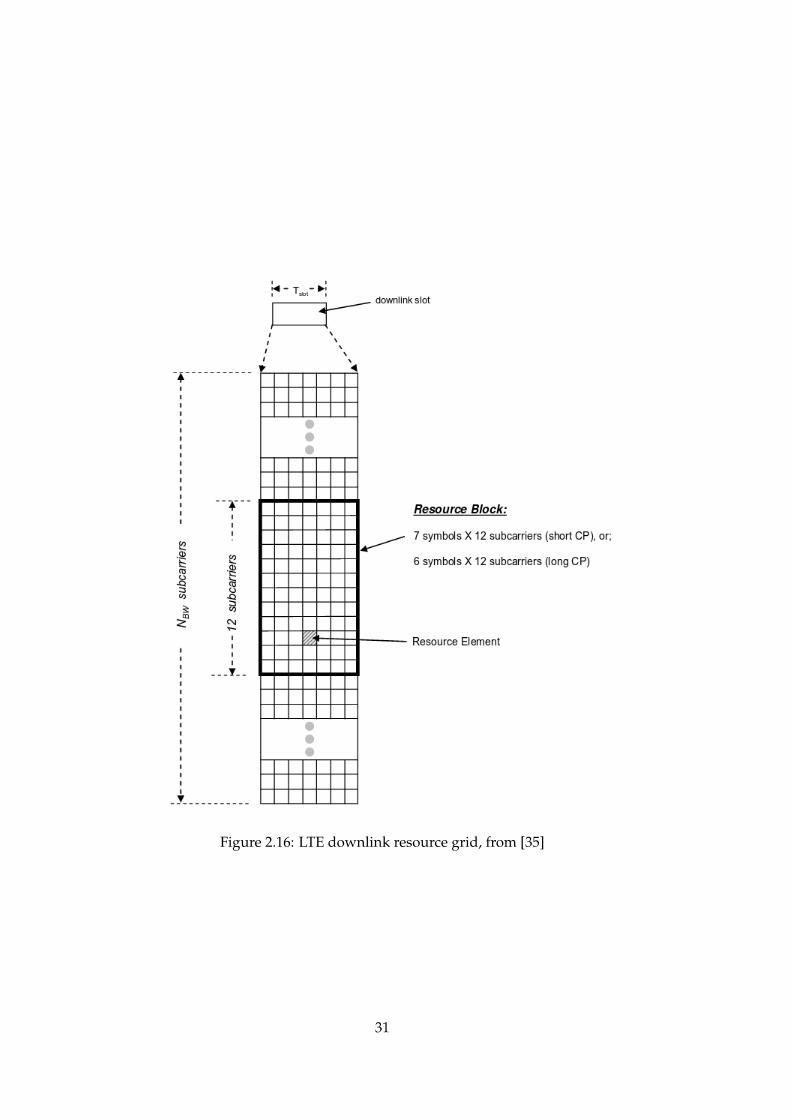
Figure 2.16: LTE downlink resource grid, from [35]
31

Figure 2.17: LTE modulation schemes, from [11]
2.5.2 Modulation schemes
A modulation scheme converts the digital bits into the form of a radiowave. The simplest example is to represent one bit per symbol, havingstarting phases of 0◦ and more as a 0 bit and 180◦ and more as 1 bit. Thedownside with this example is that is highly inefficient since transmissiondelays can be costly, and it would be more efficient to represent morebits per symbol. Figure 2.17 shows the modulation schemes used inLTE, where the Quadrature Amplitude Modulation (QAM) schemes arenormal for data transmission. While a high number of bits per symbolis desirable, it comes with a disadvantage of being highly error prone, asnoise affected radio waves can cause the receiver to misinterpret not juston bit but a whole bit sequence. Because of this, LTE dynamically changesits modulation scheme based on the condition of the radio link, using 64-QAM when there is good signal conditions and schemes more tolerant toerrors like QPSK for poorer conditions.
2.5.3 Propagation
As a signal is emitted on the wireless link, the signal spreads out as it travelsaway from the transmitter. This causes the received power of the signal tobe less than when it was when it was initially transmitted. The ratio of thetwo is called the propagation loss, also called pathloss. The signal expands ina spherical fashion, making the pathloss proportional to the radius2 [11].
Pathloss = Power(Transmitted)Power(Received)
A signal can also be reflected or blocked by object along its path, whichaffects the propagation loss.
32

2.5.4 Fading
While an ideal signal travels straight from the transmitter to the receiver,signals can reflect and "bounce" of to different paths and eventually endup at the destination receiver. The receiver may therefore receive collidingsignals, that either reinforce each other as constructive interference or canceleach other out as destructive interference. Destructive interference causes thesignal power to drop significantly, know as fading. Fading increases errorrates as the low power signals cause errors for the modulation scheme.
2.5.5 Metrics
Various metrics for measuring noise and interference is needed both forperformance analysis and channel quality indications for devices. Thefollowing sections describe some measurement quantities used for LTE.
Noise Figure
Noise figure is a measure of how much a device (such an amplifier) degradesthe Signal to Noise Ratio (SNR). For radio signals that go through multiplehops via amplifiers, the amplifiers will amplify he input signal but in theprocess also the noise from the input signal in addition to the noise figureof the device itself.[25]
Signal to Interference and Noise Radio (SINR)
The error rate depends on the Signal to Interference and Noise Radio(SINR) at the receiver.
33

34

Chapter 3
Design
3.1 Hypothesis
TCP deems a packet lost after a certain time with no delivery at all (RTO)or after receiving a number of subsequent dup-ACKs. These cases haveto deem packet loss because the transport layer cannot ever know if thepacket was actually lost or not, and not just delayed by a re-transmissionor reordering. In contrast, the ARQ on the link layer can identify actuallosses and the exact causes such as congestion or re-transmission errors.With the addition of RACK fast recovery to TCP, RACK reduces the riskthat a packet is deemed lost incorrectly due to reordering in contrast todup-ACKs. The link layer ARQ is better suited to deal with transmissionerrors on poor radio link, but the ARQ process is a cause of reordering it-self, requiring delay inducing reordering timers to avoid triggering falsepacket loss assumptions at the transport layer.
This thesis proposes a scheme for RACK and link layer ARQ tocomplement each other. RACK should ease the pressure on the ARQto satisfy in-order delivery by giving it more time to fix errors detectedon the link. In response, the ARQ needs to feed RACK with packetsto avoid triggering RACK timeouts, which can be done by immediatelyforwarding complete packets out of order instead of holding them inthe transmission windows for reordering. In theory, this scheme hopesto improve throughput and reduce latency for situations where packetswould otherwise be deemed lost.
3.1.1 Throughput
RACK reduces the number of spurious congestion reductions due to packetreordering as opposed to using dup-ACKs. This also allows the ARQ moretime to repair losses, letting the ARQ reduce congestion reductions due toactual transmission losses. Combined these two aspects should improvethroughput by avoiding unnecessary congestion windows reductions inthe TCP flow.
35

3.1.2 Latency
On the link layer, forwarding packets out of order without waiting forthe ARQ to put them in order does not deliver the in sequence packetsto the application any faster. However, giving ARQ more time to repairtransmission losses reduces the delay that would otherwise occur as aresult of re-transmitting the packet end to end. This could be particularlyuseful for short flows, given their completion time is more sensitive toindividual losses.
3.1.3 Applicability
In the standard dup-ACK scheme will deem that it needs to re-transmit apacket earlier than RACK will, given the notion of time versus sequencecounting. So if a packet loss was in fact due to congestion in the network,dup-ACK have re-transmitted the packet faster than RACK. But if the losswas falsely deemed lost, RACK and ARQ will be the victor.
The proposed scheme is therefore aimed at networks that experiencea significant level of errors and reordering that will end up producingfalse negatives for the TCP congestion control algorithm. Wireless systemsthat deploy ARQ functionality are prime candidates for this, both dueto the erroneous nature of a radio link but also the cause of reorderingfrom the ARQ. This thesis focuses on simulating an LTE network, but thistheory could also be applied to other radio link systems such as Wi-Fi andsatellite.
3.2 Related Works
3.2.1 XLR8
The concept of forwarding buffered packets out of order using RACK is nota new idea. It was proposed in XLR8: Accelerating Beyond 5G[23], which ad-dressed the struggles of transport protocols like TCP or QUIC over radiochannels. The objective was to deliver enduring solutions to slow internetprotocol acceleration for better utilisation for a varying radio channel, andto enable data flows to accelerate in constant time up to whatever peak ratethe underlying radio technology can deliver.
While the XLR8 proposal addresses a larger scope of TCP relatedbottlenecks in LTE such as capacity variability and receive window, it alsoaddresses transmission losses as a significant reason for poor end to endTCP performance, due to its inability to distinguish transmission lossesfrom congestion losses and HARQ timeout limitations.
XLR8 proposes to use Active Queue Management (AQM) to integrateinternal buffers for better control and to reduce the aggregated queuingdelay, illustrated in 3.1.
36
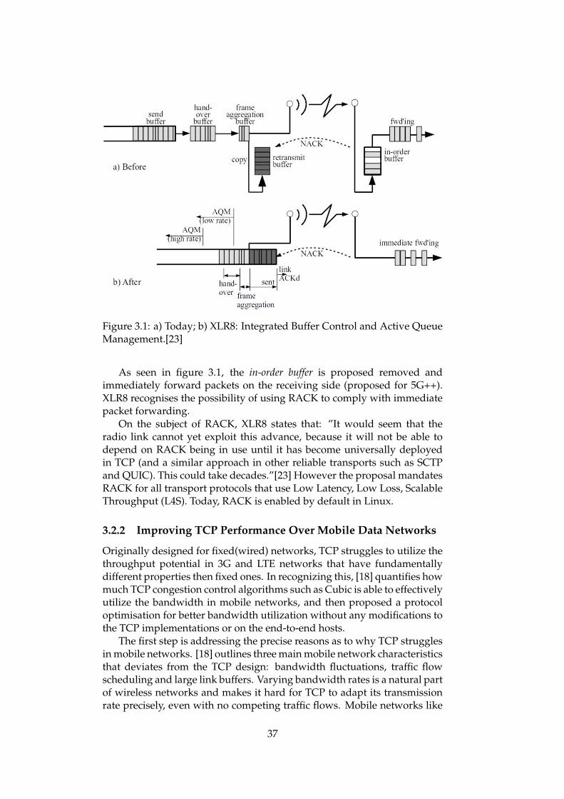
Figure 3.1: a) Today; b) XLR8: Integrated Buffer Control and Active QueueManagement.[23]
As seen in figure 3.1, the in-order buffer is proposed removed andimmediately forward packets on the receiving side (proposed for 5G++).XLR8 recognises the possibility of using RACK to comply with immediatepacket forwarding.
On the subject of RACK, XLR8 states that: ”It would seem that theradio link cannot yet exploit this advance, because it will not be able todepend on RACK being in use until it has become universally deployedin TCP (and a similar approach in other reliable transports such as SCTPand QUIC). This could take decades.”[23] However the proposal mandatesRACK for all transport protocols that use Low Latency, Low Loss, ScalableThroughput (L4S). Today, RACK is enabled by default in Linux.
3.2.2 Improving TCP Performance Over Mobile Data Networks
Originally designed for fixed(wired) networks, TCP struggles to utilize thethroughput potential in 3G and LTE networks that have fundamentallydifferent properties then fixed ones. In recognizing this, [18] quantifies howmuch TCP congestion control algorithms such as Cubic is able to effectivelyutilize the bandwidth in mobile networks, and then proposed a protocoloptimisation for better bandwidth utilization without any modifications tothe TCP implementations or on the end-to-end hosts.
The first step is addressing the precise reasons as to why TCP strugglesin mobile networks. [18] outlines three main mobile network characteristicsthat deviates from the TCP design: bandwidth fluctuations, traffic flowscheduling and large link buffers. Varying bandwidth rates is a natural partof wireless networks and makes it hard for TCP to adapt its transmissionrate precisely, even with no competing traffic flows. Mobile networks like
37

Table 3.1: Comparison of TCP throughput performance in a LTE network,from [18]
LTE uses MAC layer schedulers to schedule different user traffic flows.In fixed networks, there is no such traffic scheduling in routers and TCPhas to enforce fair bandwidth sharing in bottleneck buffers. With basestations already enforcing scheduling, it offloads this purpose from theTCP protocol. Last but not least, base stations typically use large per-userlink buffers to support link layer re-transmissions and reduce packet lossesdue to buffer overflows during large and rapid bandwidth fluctuations.[18]This enabled TCP to send more bytes without causing buffer overflow.
The first experiments did in [18] was measuring the bandwidthefficiency achieved for a set of selected TCP congestion control algorithms.The results are shown in table 3.1, comparing the average TCP throughputto the average UDP goodput. As seen from their results, the performanceis sub-optimal, 43.7% efficiency at best for Cubic. The proposed schemein [18] involves adding a mobile accelerator between the internet serverand the mobile network. This accelerator intercepts the TCP logic andadds a more opportunistic flavor. Firstly, the original purpose for theTCP receiver window was to avoid overwhelming slow receivers. Withtodays relatively higher computing power in even mobile devices, theaccelerator opportunistically forwards packets regardless of the receverwindow size (unless zero, at which point forwarding is suspended).TCP sending rate is also by design very conservative in regard to itscongestion window. Instead, the accelerator disregards the congestionwindow and does bandwidth estimation using ACK timings. To make along story short, [18] also proposed estimations in time-domain, in thiscase using fixed intervals of seconds and acknowledgement timestamps.Lastly, the accelerator allows the opportunistic transmission of new packetsduring the recovery phase, where normally TCP suspends new packettransmissions during this phase.
The end results concluded with a 97.6% bandwidth utilisation foraccelerated TCP Cubic in LTE, a 53.9% increase from the previousexperiments.
38

3.2.3 Occupancy regulation for ARQ Re-ordering Buffer
Re-ordering delay on the RLC is a product of its error control scheme basedon selective-repeat ARQ. The receiving window has to be large enough tobuffer a large burst of packets, but also increases the occupancy at the re-ordering buffer. In [28], the effects of windows sizes on RLC throughputand performance is investigated, along with a proposed scheme to regulatethe re-ordering buffer occupancy.
[28] proposes to regulate the re-ordering buffer occupancy using athreshold value. Packets arriving that are below the threshold value will beplaced in the re-ordering buffer and handled in a selective-repeat fashionas normal. Packets that go over the threshold however (but still inside thewindow) are handled using go-back-N instead, essentially discarding thepacket and wait for it to be re-transmitted.
With the approach in this thesis, there shouldn’t be an occupancyproblem, because it’s only buffering a few segments.
3.2.4 Limiting HARQ retransmissions in Downlink for PoorRadio Link in LTE
While this project proposed to increase HARQ re-transmissions if needed,[16] makes some arguments for limiting HARQ retransmissions for poorradio link conditions.
While the HARQ is a powerfull tool for link layer repairs, it alsoconsumes radio resources through both scheduling and overhead ofthe process. The proposal in [16] to reduce the maximum HARQretransmission threshold from 3 to 1 or 2 is justified by saving radioresources. When there are multiple UEs communicating with a basestation, a UE with poor radio link quality will makes less use of the radioresources compared to a UE with good radio link quality. If the UE withpoor radio link quality reduces its number of HARQ retransmissions it willreduce its throughput but free resources that can be better utilized by theother UE with good radio link quality. There is also the case of failure torepair the transmission even after 3 HARQ retransmissions, in which casethose retransmissions are considered to be wasted. In regard to robustnessfor the TCP protocol, failure to repair the transmission on the MAC can stillbe recovered by the RLC ARQ.
In simulations testing error rates versus SNR for low CQI values, [16]concludes that a HARQ retransmission threshold of 3 or higher doesdoes improve the error rate, but not substansially enough to justify theunfairness in resource allocation that comes with it. As this thesis opensfor the opportunity to increase the HARQ retransmission threshold to givethe RLC ARQ more time to repair errors, it is noted that doing so couldnegatively impact other UEs by taking more of the shared radio resources.
39

3.2.5 Advice to link designers on link Automatic Repeat reQuest(ARQ)
An optimal design for the protocol performance on one layer may be affectprotocol performance on other layers. For example, TCP designers need tobe aware that the IP protocol operates over a diverse range of underlyingsubnetworks on its route. [14] outlines some important considerationsregarding link ARQs impact on the performance of higher layer TCP orUDP protocols.
Perfect reliability is not required for IP networks for optimal perfor-mance, and thus may drop packets due to a number of reasons like queu-ing, faults etc. It has long been widely understood that perfect end-to-endreliability can be ensured only at or above the transport layer, enter the end-to-end principle.[26] ARQs on the link can be used to make the link complywith the needs of the higher layer protocols such as reordering and delay,to make sure these upper layers do not have their performance degradedby link layer operations. [14] discusses the pros and cons of using differentARQ implementations for transport protocol performance.
ARQs can be implemented with variable persistence. A perfectlypersistent (reliable) ARQ, which is the type implemented in the RLC ARQin LTE, provides reliable service to the upper layers, using high degreesof reordering and retransmissions. If a the ARQ fails to retransmit alost frame, the ones that are received out-of-order are discarded insteadof forwarded in order to avoid inducing congestion avoidance signals athigher layers. Such reliability comes at the expense of high end-to-enddelay, which can be desireable for TCP but not for non-reliable protocolssuch as UDP. Non-reliable transport protocols instead benefit from ARQswith lower persistence, with lower timeout thresholds for reduced delayand less guarantees for reliable delivery. This poses a problem when usingmultiple flows through the same ARQ, as different protocols on differentflows may require different implementation schemes.
In conclusion, [14] advises ARQ designers to consider the implicationsof their design on the wider Internet, as it can be very hard to generaliseARQ schemes for transport protocols, especially considering that theremay be multiple ARQs along the end-to-end network route. Also, theapproach of being able to identify flows at the link layer is noted, whichwould enable ARQs to implement low persistancy but high-persistancymechanisms for TCP specifically. Algorithms to implement this remain anarea of research[14], and is also required to realise this project in its fullpotential.
3.3 Proposed Scheme
The proposed scheme of using RACK with a modified link error-correctingprocedure aims at examining the measures of the effect this scheme willhave on the performance of a number of TCP flows in comparison to thedefault schemes and congestion control algorithms. The design is not in-
40

tended to be something complete that could be deployed immediately.Rather, it’s purpose is to apply the previously presented idea to incre-mentally focus more packet re-transmission instances from the end-to-endtransport protocols to the link protocols. Since the scope of the design ofthis scheme is narrowed down to such an extent, it would be biased to com-pare its results directly to default schemes that account for a much widerscope and applicability. Therefore this section also addresses limitationssuch as technical requirements and use cases that would be needed for thisscheme to truly level with comparative schemes.
The key modification required for the proposed scheme is packetforwarding to bypass the delay from the HARQ reordering procedure.Additionally, tuning of timers such as reordering timers and increasing re-transmission thresholds are considered. Lastly technical requirements andproposed solutions to extend the applicability of the scheme are discussed.
3.3.1 Immediate Forwarding
The end goal of this scheme is to make sure that complete IP packets areimmediately forwarded up to higher layers to reach the TCP protocol, by-passing any HOL blocking. However these IP packets are encapsulatedinto data units in lower layers going down the LTE protocol stack, meaningthat forwarding a lower layer data unit such as a MAC PDU could poten-tially mean forwarding multiple IP packets, theoretically making all dataunits from the IP layer and below candidates for forwarding. The problemhowever arises regarding functions such as segmentation and multiplex-ing, because there is no guarantee that a data unit on layer 2 or layer 1are divided in line with the IP packets in the payload. Such data units(PDUs) could instead contain incomplete IP packets as a result of segmen-tation, and it would be counter-effective to immediately forward these asthey would cause errors for the network protocol and again for the remain-ing parts of the IP packet.
Ideally, in the fashion of forwarding IP packets, one would want to for-ward all PDUs. However looking down the LTE protocol stack, PDUs thatcan realistically be forwarded can be identified. For a clear overview ofhow the IP packets are packed through the LTE protocol stack, see figure2.10 from the previous chapter. IP packets first arrive at the PDCP layer,where they are PDCP SDUs put into PDCP PDUs. The PDCP compressesthe IP header using its ROHC procedure, but PDCP PDUs are still capableof being forwarded since the decompression uses the COUNT value whichis composed of the PDCP SN [4], and the decompression of packets is nothalted by out-of-order sequencing.
PDCP PDUs, containing complete IP packets, are sent to the RLC asRLC SDUs. The RLC layer may concatenate or segment this data, depend-ing on whether the conditions of the radio link are good enough to carrymultiple RLC SDUs or so poor that an RLC SDU must be segmented over
41

multiple RLC PDUs. Even if the signal conditions are good, RLC wantsto fill up its transmission opportunity and will segment parts of an RLCSDU to utilise the remaining byte space allowed. This means that RLCPDUs should not be immediately forwarded as a whole because they maycontain an incomplete RLC SDU and therefore incomplete IP packet. How-ever if the RLC PDU contains one or more complete RLS SDUs, thesecan be forwarded individually and incomplete RLC SDU segments canbe buffered until new segments make them complete. This requires man-agement to make sure that the incomplete RLC SDU segments are reassem-bled correctly in regard to its sequence number and whether the segmentis the first, last or even a middle part of the complete RLC SDU.
MAC PDUs containing MAC SDUs are already forwarded in the sensethat they are immediately shipped to the RLC when the MAC PDU is com-plete because in E-UTRAN HARQ reordering is done at the RLC ARQ in-stead of buffering locally on the MAC layer. Going deeper to the PHY layer,the MAC PDU is re-assembled by the receiver by time-divided sub-frames.These sub-frames could in theory contain complete IP packets, but becauseof the time-domain there is no way to confirm that given the structural ar-chitecture of the data units. Even if one could detect IP packets within thesub-frames, forwarding these would break the entire structure of the LTEprotocol stack in regard to header data and packet control.
Immediately forwarding PDUs must therefore be limited to forwardingcompleted RLC SDUs on the RLC layer up the the PDCP layer, withmechanisms to correctly re-assemble incomplete RLC SDU segments.
3.3.2 Threshold Tuning
Reordering timers and re-transmission thresholds are by default set to val-ues that are high enough to allow reordering but low enough not to causetoo much delay. The main limits in question are the RLC reordering timerand the HARQ maximum re-transmission limit.
When the RLC receives a RLC PDU that is out-of-sequence, it startsa reordering timer. While the reordering timer is running, any duplicateRLC PDUs are discarded and positive or negative acknowledgement isprohibited.[5] Any additional RLC PDUs that are received out-of-sequencewhile the timer is running are buffered in the reception window. The timerwill continue to run until the expected SN arrives or until the timer expires.If the expected SN arrives, the timer is cancelled and the expected RLCPDU is delivered along with any packets of higher SN that fall in order.This is illustrated in figure 3.2, where the RLC reordering timer waits for aHARQ re-transmission.
If the timer expires, the RLC deems the expected PDU lost and start de-livering the RLC SDUs that were buffered during the reordering timer. Thereason the reordering timer prohibits status reporting when running is togive the HARQ more time for re-transmission before the RLC ARQ starts
42
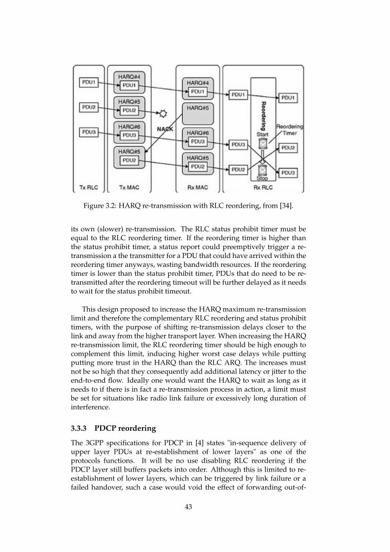
Figure 3.2: HARQ re-transmission with RLC reordering, from [34].
its own (slower) re-transmission. The RLC status prohibit timer must beequal to the RLC reordering timer. If the reordering timer is higher thanthe status prohibit timer, a status report could preemptively trigger a re-transmission a the transmitter for a PDU that could have arrived within thereordering timer anyways, wasting bandwidth resources. If the reorderingtimer is lower than the status prohibit timer, PDUs that do need to be re-transmitted after the reordering timeout will be further delayed as it needsto wait for the status prohibit timeout.
This design proposed to increase the HARQ maximum re-transmissionlimit and therefore the complementary RLC reordering and status prohibittimers, with the purpose of shifting re-transmission delays closer to thelink and away from the higher transport layer. When increasing the HARQre-transmission limit, the RLC reordering timer should be high enough tocomplement this limit, inducing higher worst case delays while puttingputting more trust in the HARQ than the RLC ARQ. The increases mustnot be so high that they consequently add additional latency or jitter to theend-to-end flow. Ideally one would want the HARQ to wait as long as itneeds to if there is in fact a re-transmission process in action, a limit mustbe set for situations like radio link failure or excessively long duration ofinterference.
3.3.3 PDCP reordering
The 3GPP specifications for PDCP in [4] states "in-sequence delivery ofupper layer PDUs at re-establishment of lower layers" as one of theprotocols functions. It will be no use disabling RLC reordering if thePDCP layer still buffers packets into order. Although this is limited to re-establishment of lower layers, which can be triggered by link failure or afailed handover, such a case would void the effect of forwarding out-of-
43

order RLC SDUs. During this process, PDCP keep a Reordering_Windowvariable with a size half of the PDCP SN space. Disabling reordering inthis case could be done by for example disabling such functions that aretriggered by such sequencing. However, this project does not cover thehandover process, and as will be described in the next chapter the PDCPimplementation of the simulator does not support such a function. Thismeans that the experiments will automatically bypass this aspect, but it isnoted as a limitation. The RLC reordering scheme will still be in place andout-of-sequence deliveries at the RLC will still trigger the reordering timer,however the out-of-sequence RLC PDUs that are buffered are not helduntil the reordering timeout or the reception of the expected SN. Instead,completed RLC PDUs are inspected to look for complete RLC SDUs, whichare then individually forwarded. When the reordering timer times out orthe expected SN arrives and start sending packets in order, the completedRLC SDUs buffered have already been forwarded.
3.3.4 RACK awareness
While immediate forwarding is designed to work for RACK, it would beseverely damaging for TCP flows that do not use RACK and does dependon receiving packets in order. Therefore there needs to be a mechanismfor the RLC to differentiate between whether data packets should be for-warded or reordered. This is another limitation that is not implementedbut is included as theoretical proposals.
One solution could be to peek at the available IP headers from the IPpackets stored in a packet payload. RACK compliant packets could beidentified using the ECN bits of the IP header, assuming that an end-to-end connecting employing ECN also uses RACK. As the work on RACKprogresses, and is already enabled in Linux by default, this is not animprobable assumption to make, although still not completely thorough.These identified RACK data units can then be forwarded while others cannot. There is an additional problem with this method regarding the PDCPheader compression. If the PDCP compresses the IP headers, lower layersare unable to inspect the IP headers. Disabling PDCP header compressionwould solve this but is highly undesirable, since it would add severemeasures of overhead to the data transmission.
A better but more extensive solution could be to extend the LTE stackfunctionality. For RACK compliant connections, the RRC which assignsthe RLC AM mode, could also configure the immediate forwarding schemeeither through additional control variables or a modified duplicate of theAM mode. There would also have to be dynamic changes to the MACscheduler controlling the HARQ and the mac re-transmission threshold,which could also be configured by higher layers. Packets can be identifiedabove the PDCP layer as they would be classified into the different bearers.
44
Chapter 4
Implementation
4.1 NS-3
Network Simulator version 3 (NS-3) is an open-source network simulatorwhich is publicly available for research and educational purposes.[2] It is adiscrete-event simulator, meaning that it models all events in a simulatedsystem as a discrete sequence of events. Any event occurs within it’s owntime instance in which it marks any changes it imposes on the system be-fore jumping to the next event.
The simulator, written in C++, revolves around creating and configur-ing different nodes in the simulated network environment, which can rep-resent any network entity such as user equipment, terminals, routers etc.These nodes can be configured by using the ns3 Model Library, by for exam-ple having a node resemble a smartphone by using the network module toinstall the required devices and networking stacks and the mobility modelto map movement over time. Although a very powerfull tool, there arestill limitations in regard to support or functionality of some technologicalspecifications. However, being an open-source project allows users to im-plement and adapt their own features or extensions to the already existingns3 implementation.
4.1.1 LTE Module
The ns3 LTE Module is used to simulate an LTE network. An overview ofthe module is illustrated in figure 4.1. The module is a product of two maincomponents:
• LTE Model: includes the LTE Radio Protocol stack (RRC, PDCP, RLC,MAC, PHY). These entities reside entirely within the UE and the eNBnodes. This model simulates spectrum aspects that occurs on a radiolink such as interference. To accurately model packet scheduling andinterference, the model needs a granularity of one Resource Block(RB).
• EPC Model: includes core network interfaces, protocols and entities.
45

Figure 4.1: An overview of the LTE-EPC simulation model from [2]
These entities and protocols reside within the S-GW, P-GW and MMEnodes, and partially within the eNodeB nodes.
Together the LTE-EPC simulation model generates a network routefrom a UE through whatever node is connected to the LTE gateway. Notethat in this model the S-GW and P-GW are combined into a single SG-W/PGW node that hold the functionality of both. This eliminates the needfor the S5/S8 interface specified by the 3GPP, being the only major butharmless deviation from the LTE specifications. The other interfaces andprotocols follow 3GPP specifications, even though the implemented codemight be tailored differently for the scope of the simulator but generatingthe desired output. However some implementations of protocols may belimited by only being partially implemented.
The S1-AP and S11 interfaces are used by the control plane of theEPC model, used by the MME to control its connected base stations andgateways. On the data plane, the X2 interface connects base stations whichin turn connect to the gateway using an S1-U interface. The eNB connects tothe UE endpoint over the radio link. The S1-U interface between the eNBand the SGW/PGW encapsulates packets over GPRS Tunneling Protocol(GTP), UDP and IP as done in real LTE systems.[2] The overall protocolstack that a data packet transverses through the data plane from end toend is illustrated in figure 4.2.
Propagation and Fading Models
There are many different propagation models available to produce pathlosson the radio link. These models range from simple models such aspure randomness and range models, to more complex models that modelenvironments or buildings. The pathloss is computed for downlink anduplink separately, and only for communication between UE and eNB. TheFriis propagation loss mode is the default propagation model.
46

Figure 4.2: LTE-EPC data plane protocol stack, from [2]
Table 4.1: Delay profiles for E-UTRA channel models, from [6]
The fading loss model is based on precalculated fading traces. Suchtraces can be generated with 3GPP specified models from [6], which usesdelay profiles in the form of a ’tapped delay-line’ characterised by anumber of taps at fixed positions on a sampling grid, which are furthercharacterised using delay spread and maximum delay spanned by the taps.These profiles are then used in combination with a maximum Dopplerfrequency to generate profiles such as the Extended Pedestrian A (EPA),Extended Vehicular A model (EVA) and Extended Typical Urban model(ETU), whose model parameters are shown in table 4.1. These models areselected to represent low, medium and high delay spread environments. Inaddition the ns3 fading model takes user speed as an important variable,where typical values include 0 to 3 kmph for pedestrian scenarios and 30to 60 kmph for vehicular scenarios, both being considered urban scenarios.Three such models are provided by ns3:
• EPA: Pedestrian with speed 3 kmph.
• EVA: Vehicular with speed 60 kmph.
• ETU: Typical urban with speed 3kmph.
47

Spectrum Model
The radio spectrum is modelled using the carrier frequency and transmis-sion bandwidth. The spectrum model is the base for transmission speedand error models when nodes communicate over a radio link. The spec-trum model is assigned for every eNB, where different eNBs can have dif-ferent spectrum models. A UE will automatically use the spectrum modelof the eNB it is currently attached to.
Data transmitted over the radio spectrum on the data plane (PDSCHand PUSCH), are sent over resource blocks. The error model used over thespectrum is therefore in terms of Code Block Error Rate (BLER). BLER per-formance is modelled using BLER curves, that outputs the TB size giventhe BLER, SINR and MCS.
There are also error models for the control plane, but for this projectthis model will be disabled to ensure an ideal error free downlink/uplinkcontrol channel for simplicity and to avoid tampering with the data errormodel results.
HARQ
HARQ is implemented with Incremental Redundancy (IR) combined withstop-and-wait processes, and is enabled by default. UL transmissionsare synchronous while DL transmissions are asynchronous as per thestandard. There are 8 HARQ processes on the MAC layer, controlled by aspecified MAC scheduler. These processes are illustrated in 4.3. The HARQimplementation is active on both PHY and MAC layers, despite begin aMAC layer technology. The PHY layers implements HARQ functionalityrelated to its layer to support decodification buffers for IR management.
The MAC schedulers that control the HARQ processes mostly revolvearound fairness among the UEs using the eNB, such as Round-Robin,proportionality or token based schemes. Since this project is limited to oneUE node, the Maximum Throughput (MT) Scheduler is chosen to maximiseoverall throughput of the eNB, since it is not a problem in this case that theMT scheduler cannot provide fairness to UEs in poor channel conditions.
RLC
The RLC implementation includes a model for each of the three 3GPPspecified entities Transmission Mode (TM), Unacknowledged Mode (UM)and Acknowledged Mode (AM). In addition, ns3 provides a SaturationMode (SM) model, an unrealistic model for simplified cases.
The implementation interfaces with the PDCP by using sending andreceiving PDCP PDUs through its Service Access Point (SAP). Similarlythe RLC interfaces with the lower MAC layer by sending/receiving RLCPDUs, but in addition the MAC entity uses NotifyTxOpportunity to notify atransmission opportunity to the RLC entity, and the RLC uses ReportBuffer-Status to report the size of pending buffers in the transmitted peer. This
48

Figure 4.3: LTE HARQ processes scheme, from [2]
project only uses of the Acknowledged Mode (AM) RLC.
The ns3 implementation of AM RLC uses the following three buffers:
• Transmission Buffer: queue with RLC SDUs delivered from the PDCP.SDUs are silently dropped when the buffer size is full.
• Transmitted Buffer: queue with transmitted RLC PDUs that have notyet been ACKed or NACKed.
• Retransmission Buffer: queue with RLC PDUs considered for retrans-mission, meaning they have been NACKed or timed out.
When a RLC SDU is received from the upper PDCP layer, it is placed inthe transmission buffer and a report on the buffer status is sent to the MACfor scheduling purposes. When the MAC scheduler sees a transmissionopportunity it notifies the RLC, which in turn creates an RLC PDU usingthe buffered SDUs in the transmission buffer and copies the data to thetransmitted buffer before it is send to the MAC.
In the textitns-3 implementation, AM RLC generally wants to send ex-actly one RLC PDU per transmission, even if the transmission opportunityis large enough to hold an additional segment. When the transmission op-portunity is smaller than the RLC PDU size, AM RLC will segment andconcatenate as needed to fill the opportunity. [5] specified that there is noconcatenation in the retransmission buffer. The ns3 implementation fol-lows this by not supporting re-segmentation in the retransmission bufferand rather waits for a sufficiently large transmission opportunity instead.
Currently the AM RLC implementation does not support the followingprocedures in [5]:
49

• Send an indication of successful delivery of RLC SDU.
• Indicate to upper layers that max retransmission limit has beenreached.
• SDU discard procedures.
• Re-establishment procedure.
PDCP
The PDCP implementation in ns3 is simple, and only features themost basic functions needed from this layer. It supports the followingprocedures in [4]:
• Transfer of data.
• Maintenance of PDCP SNs.
• Transfer of SN status.
Among the procedures not supported from [4] that relates to this projectare:
• In-sequence delivery of upper layer PDUs at re-establishment oflower layers.
• Duplicate elimination of lower layer SDUs at re-establishment oflower layer for RLC AM mapped radio bearers.
• Header compression and decompression of IP data flows during theROHC protocol.
• Duplicate discarding.
• Timer based discarding.
4.1.2 DCE
Direct Code Execution (DCE) is a framework for ns-3 that providesfacilities to execute, within ns-3, existing implementations of userspaceand kernelspace network protocols or applications without source codechanges.[1] For applications that are not already implemented in ns-3, DCEcan be used to to run applications on the Linux networking stack and haveits data traffic routed through the ns-3 simulator. This project uses thecurrently latest version DCE-1.9.
50
Linux Kernel library
DCE uses a kernel compiled as a library. A ns-3 simulation that needs itsapplication to use the Linux network stack does so by linking to this kernellibrary. By default DCE comes with net-next-sim, a simplified and slightlymodified kernel that compiles into a kernel library that is compatible withDCE. However net-next-sim is now deprecated and does not contain therequired networking code for this project, so instead its successor net-next-nuse will be used, also called LibOS.
Most desirably one would want to use the latest version of the Linuxkernel. There is a work in progress to integrate ns-3 with the Linux kernellibrary (LKL), which reuses the Linux kernel code more extensively, but asstated in [30] it remains uncertain when this is finished.
4.2 Simulation Setup
The core simulation setup implements a single UE communicating with aremote host over an LTE network.
The setup revolves around four nodes:
1. UE node
2. eNB node
3. SGW/PGW node
4. Remote host node
These nodes are installed and interconnected as needed to representtheir intended network entity, explained in more detail below. Figure 4.4shows an overview of the simulation nodes in action, generated usingthe ns-3 NetAnim module which traces all ns-3 nodes and their actions,outputting an animation of the simulation in XML format. The imagesrepresenting the nodes are added for better visual representation.
4.2.1 User Equipment node
The UE node has a Linux networking stack installed, configuring network-ing parameter such as congestion control algorithm from the simulationparameters. LTE UE Net devices are install for communicating over a ra-dio link, and is then attached to the eNB node. For network purposes, thenode is assigned an IP address and the Linux ip tables are configured forrouting to the remote host. Lastly the UE starts an iperf application, config-ured as a client targeting the remote node IP address. The UE node uses aconstant position mobility model, and by default does not move through-out the simulation, otherwise it moves at a constant velocity.
51

Figure 4.4: NetAnim animation of the simulation setup.
4.2.2 Evolved NodeB node
The eNB node is initialised using the LTE module. This node is responsiblefor modelling the radio environment, since when the UE node attacheditself it inherits these configurations. Simulation parameters can overridedefault values such as noise or spectrum properties. The eNB node sets thedesired pathloss and fading model from the simulation parameters, as wellas configuring the MAC scheduler.
4.2.3 SGW/PGW node
The gateway node attaches to the eNB node over the S1-U interface link.Net devices are installed and IP address is assigned for IP routing. TheSGW/PGW node connects to the remote host node over a point-to-pointlink. For the simulation results to focus on LTE aspects, the point-to-pointlink from the gateway to the remote host is implemented as an error-free100 Gigabit per second link to ensure that this is not the network bottleneck.
4.2.4 Remote host node
The remote host is similar to the UE node except from the LTE aspects.The remote nodes uses the Linux stack with RACK enabled by default, netdevices for physical links and the point-to-point link to the gateway node.
4.2.5 Traces and Data Collection
The various devices installed on the nodes are enabled to output trace filesdisplaying LTE radio stack operations such as number of transmitted orreceived bytes, delay, data unit sizes etc. Network packets are captured aspcap files for those net devices that allow it. Before every simulation, an
52

ns-3 Flow Monitor is installed that hooks onto packet flows observed underthe simulation, outputting end-to-end statistics.
4.3 HARQ Re-transmission Limit
The HARQ retransmission limit in ns-3 is hard-coded to a constant of value3, the 3GPP specified threshold. The different HARQ schedulers all havetheir own implementations, all with the retransmission limit hard-coded.To modify the retransmission limit, we must modify the scheduler flavorthat is being used in the main simulation program, which in this case is theTime Domain Maximize Throughput scheduler.
The retransmission limit is implemented as a simple if -statement,which drops a HARQ process if it triggers this case. In order to increasethe HARQ retransmission limit, the constant is simply changed to thedesired value. This is done for both instances of the if -statment, onefor the uplink function TdMtFfMacScheduler::DoSchedUlTriggerReq and thedownlink function TdMtFfMacScheduler::DoSchedDlTriggerReq.
The optimal solution to increase the retransmission limit would havebeen to change the constant into a run-time attribute configured by themain simulation program. However due to simplicity and time constraints,several compiled versions of the simulator with different threshold valuesfrom 3 to 8 were implemented.
4.4 RLC AM Immediate Forwarding
The implementation of immediate forwarding completed RLC SDUs isdone by modifying the ns-3 source code files for the receiver side ofthe RLC AM, namely lte-rlc-am.cc and lte-rlc-am.h. The changes involvemodifications in of the void LteRlcAm::DoReceivePdu function, and theaddition of the voidLteRlcAm::Forward function which forwards completeRLC SDUs and handles re-segmentation. Before describing the details, anoverview of the original code is presented as a basis for the modifications.
4.4.1 Original implementation
The original code starts by initialising all variables and timers as config-ured by the RRC and default values. The core functions are DoReceivePdu,which handles an RLC PDU received from the MAC, DoNotifyTxOpportu-nity which is called by the MAC to signal an opportunity and Reassem-bleAndDeliver that delivers buffered RLC SDUs from the receiver window.PDCP PDUs (RLC SDUs) received from the PDCP are put into the trans-mission buffer. When the MAC calls DoNotifyTxOpportunity that signals asufficiently large transmission opportunity, this function takes RLC SDUsfrom the transmission buffer and packages them into an RLC PDU fittingof the opportunity size and transmits it to the MAC. DoReceivePdu takes re-ceived RLC PDUs and implements ARQ functionality. Both of these func-tions differentiate between control PDUs and data PDUs, each with their
53

own procedure. For each data RLC PDU received with the expected SN,ReassembleAndDeliver takes each completed RLC PDU in the window witha SN equal to or higher than expected one (m_vrR) and extracts completeRLC SDUs. RLC SDU segments are temporarily kept until its match isfound, and discarded if not. This is done by keeping the reordering statesshown in 4.1.
Listing 4.1: lte-rlc-am.h reordering states
SequenceNumber10 m_vrH ; / / / < VR(H)
/ * ** Counter s . See s e c t i o n 7 . 1 in TS 36 .322* /
u i n t 3 2 _ t m_pduWithoutPoll ; / / / < PDU w i t h o u t p o l lu i n t 3 2 _ t m_byteWithoutPoll ; / / / < b y t e w i t h o u t p o l l
/ * *
For example When a RLC PDU contains an RLC SDU segment, it storesthe segments in m_keepS0 and sets the state to WAITING_SI_SF. For the nextRLC PDU, if in sequence, will then concatenate its starting segment to thestores one and deliver it as a complete RLC SDU, resetting the reassemblingstate. If it is out of sequence, the kept segment is discarded and state reset.
RLC PDUs are stored in a data structure containing the sequencenumber, byte segments and Boolean variable for whether the RLC PDU iscomplete or not, given that a RLC PDU may be sent as multiple segmentsif transmission opportunities are small.
4.4.2 Modification
Rewinding back to the design and motivation, this is where out-of-orderIP packets are delayed because out-of-sequence RLC PDUs are buffered inthe window waiting for a reordering timeout or another packet to move thereception window. In order to forward out-of-sequence RLC PDUs, a fewadditions are added to DoReceivePdu. In the original implementation, whenreceiving a RLC PDU, the function first checks if the packet is a duplicateor if its within the receiving window or not, in which it is discarded, andwhether the packet is complete or not. For a new RLC PDU that has passedthese tests, DoReceivePdu checks if the sequence number is the expectedone (m_vrR), and only if so does it initiates the procedure of delivering thebuffered packets. For this immediate forwarding scheme, another test caseis added for which the sequence number is higher than m_vrR, meaningthat at least this one packet is received out of order and forwarding shouldtake place. For every such out-of-order packet received, the forwardingfunction Forward () is called, which iterates the window and forwards anycomplete RLC SDUs it can find and re-assembling segments if possible.
54

The forwarding function is described in detail later. In order to maintainthe core structure of the original code, RLC PDUs that have had all theirpayload forwarded are not deleted from the window. When reorderingtimes out or the expected packet arrives, the RLC moves the windows in-crementally delivering packets in order, but to avoid having the RLC try todeliver a packet that has already been forwarded, and additional variable isadded to the RLC PDU data structure, m_delivered, marking it as forwarded.
It is noted that this may not necessarily be the most optimal approachin regards to performance.
Listing 4.2: lte-rlc-am.h RLC PDU data structure
** \param packet the packet*/
void ReassembleAndDeliver ( Ptr <Packet > packet ) ;
bool Forward ( SequenceNumber10 seqNumber ) ;
/ * *
PDUs marked as delivered do not invoke the delivery functionReassembleAndDeliver, as it has already been processed with Forward. IfForward has modified the RLC PDU by forwarding complete RLC SDUs butbeen unable to re-assemble any remaining segments, it will have modifiedthe packet payload by removing the forwarded RLC SDUs, and only thesegment will remain in the packet payload under the normal deliveryprocedure.
55

Listing 4.3: lte-rlc-am.cc expected SN and out-of-orderforwarding
}
/ / − i f x = VR(R) :/ / − i f a l l b y t e s egments o f t h e AMD PDU with SN = VR
(R) a r e r e c e i v e d :/ / − up da t e VR(R) t o t h e SN o f t h e f i r s t AMD PDU
with SN > c u r r e n t VR(R) f o r which not a l l b y t es egments have been r e c e i v e d ;
/ / − up da t e VR(MR) t o t h e upda t ed VR(R) +AM_Window_Size ;
/ / − r e a s s e m b l e RLC SDUs from any b y t e s egments o fAMD PDUs with SN t h a t f a l l s o u t s i d e o f t h e r e c e i v i n gwindow and in−s e q u e n c e b y t e s egments o f t h e AMD PDUwith SN = VR(R) , remove RLC h e a d e r s when do ing so and
d e l i v e r t h e r e a s s e m b l e d RLC SDUs t o upper l a y e r ins e q u e n c e i f no t d e l i v e r e d b e f o r e ;
i f ( seqNumber == m_vrR ){
std : : map <uint16_t , PduBuffer > : : i t e r a t o r i t =m_rxonBuffer . f ind ( seqNumber . GetValue ( ) ) ;
i f ( i t != m_rxonBuffer . end ( ) &&i t −>second . m_pduComplete )
{i t = m_rxonBuffer . f ind ( m_vrR . GetValue ( ) ) ;i n t f i r s t V r R = m_vrR . GetValue ( ) ;while ( i t != m_rxonBuffer . end ( ) &&
i t −>second . m_pduComplete ){
i f ( ! i t −>second . m_delivered ){
NS_LOG_LOGIC ( " Reassemble and Del iver (SN = " << m_vrR << " ) " ) ;
NS_ASSERT_MSG ( i t −>second . m_byteSegments .s i z e ( ) == 1 ,
" Too many segments . PDUReassembly processdidn ’ t work " ) ;
ReassembleAndDeliver ( i t −>second .m_byteSegments . f r o n t ( ) ) ;
}
m_rxonBuffer . erase ( m_vrR . GetValue ( ) ) ;
m_vrR++;m_vrR . SetModulusBase ( m_vrR ) ;m_vrX . SetModulusBase ( m_vrR ) ;m_vrMs . SetModulusBase ( m_vrR ) ;m_vrH . SetModulusBase ( m_vrR ) ;i t = m_rxonBuffer . f ind ( m_vrR . GetValue ( ) ) ;
NS_ASSERT_MSG ( f i r s t V r R != m_vrR . GetValue ( ) ," I n f i n i t e loop in RxonBuffer " ) ;
}
56

NS_LOG_LOGIC ( "New VR(R) = " << m_vrR ) ;m_vrMr = m_vrR + m_windowSize ;
NS_LOG_LOGIC ( "New VR(MR) = " << m_vrMr) ;}
}
57

4.4.3 Forward ()
The Forward function is a modified version of the ReassembleAndDeliverfunction. The original ReassembleAndDeliver function takes an RLC PDUas argument and strips it of its RLC header. The header information isused to correctly extract the RLC SDU segment(s) in the payload, puttingRLC SDUs and segments into a buffer. The framing information from theRLC headers indicates whether the the payload contains segments that areeither the first part or the last part of a complete RLC SDU. If the payloadcontains the first and last bytes of an already complete RLC SDU. Reassem-bleAndDeliver has to account for a large set of cases, from the framing in-formation to the re-assembling status and whether or not the RLC PDU isin order. For example, if the previous call to the function found an incom-plete segment which was kept for the next call to find its missing piece,the next function call might contain such a segment but if the RLC PDUwas out-of-order these two segments cannot be concatenated because theydo not belong to the same RLC SDU, in which the kept segment has to bediscarded and re-assembly status updated. For each complete RLC SDU,it is delivered directly to the PDCP using the Service Access Point (SAP),namely ReceivePdcpPdu(Ptr < Packet > p).
Forward() is a recursive function. Instead of being a void function callthat only processes one RLC PDU, it transverses all the completed RLCPDUs in the reception window each time it is called. To indicate the baseSN at which to start iterating the window, the function takes this sequencenumber as an argument, which will be the expected SN (m_vrR) plus one.Sequence slots in the window that are incomplete or marked as deliveredare simply skipped. The idea behind recursively iterating the out-of-orderRLC PDUs is for segment re-assembly, since a newly added RLC PDUmight contain segments that complete that of previously processes RLCPDUs which had to keep those segments. Recursion also reduces somecomplexity in regard to state variables. The recursion ends when there areno more complete RLC PDUs to transverse in the reception buffer.
Instead of decisively removing the RLC header from the packet, For-ward merely peeks at the information. This is because it is not given thatthe packet is to be delivered or not, as it may contain segments that do nothave a complementary match in the reception window. Therefore a copy ismade of the original packet, and a copy is processed. If the copy success-fully forwards all RLC SDUs, the original PDU is marked as delivered, andif no changes took place, it is left intact in its original state. If some RLCSDUs were forwarded but there are remaining segments, a new packet ismade by adding an updated RLC header to the remaining segments, andthe original packet is replaced by the updated one.
58

Listing 4.4: Forward recursion
{NS_LOG_LOGIC ( seqNumber << " i s OUTSIDE the r e c e i v i n g
window" ) ;return f a l s e ;
}}
boolLteRlcAm : : Forward ( SequenceNumber10 seqNumber ){
Ptr <Packet > packet = 0 ;
for ( u i n t 1 6 _ t i = seqNumber . GetValue ( ) ; i < m_vrH . GetValue( ) ; i ++)
{s td : : map <uint16_t , PduBuffer > : : i t e r a t o r i t =
m_rxonBuffer . f ind ( i ) ;i f ( i t != m_rxonBuffer . end ( ) && i t −>second .
m_pduComplete &&! i t −>second . m_delivered )
{i f ( i == seqNumber . GetValue ( ) )
{packet = i t −>second . m_byteSegments . f r o n t ( ) ;
}e lse
{keepS = 0 ;Forward ( SequenceNumber10 ( i ) ) ;
}break ;
}}
The function returns a Boolean value to signal the calling functionwhether the kept segment was delivered or not. This is demonstratedin Listing 4.5 which is the case for a RLC PDU that has no last byte,meaning it contains an incomplete segment at the end. First it iteratesthe SDU buffer to forward any completed SDUs extracted. The "tail"segment is temporarily stored and copied to the shared re-assembly pointerkeepS. However the function does not know if there are any in-order RLCPDU(s) received that can complete the remaining part of this tail segment.Therefore it starts the next recursive iteration at the desired sequencenumber that can complete the segment. If the function returns true, it measthe tail segment was successfully re-assembled and delivered by the nextiteration, and the packet can be marked as delivered. If it returns false,either no such RLC PDU has been received or it was unable to re-assemblethe RLC SDU, in which case the tail segment much be kept. If in additionto keeping the segment the counter variable (which counts delivered RLCSDUs) is zero, no changes were made and the function should abort.
59

Listing 4.5: RLC SDU re-assembly case
NS_LOG_DEBUG ( " ( 1 1 ) Forward SN( " << seqNumber .GetValue ( ) << " ) Time : " << Simulator : : Now ( ) .GetSeconds ( ) ) ;
m_rlcSapUser−>ReceivePdcpPdu ( * i t p ) ;counter ++;
}
i t −>second . m_delivered = t rue ;Forward ( seqNumber + 1 ) ;return r e t v ;
case ( LteRlcAmHeader : : FIRST_BYTE | LteRlcAmHeader : :NO_LAST_BYTE) :
while ( sdusBuffer . s i z e ( ) > 1 ){
NS_LOG_DEBUG ( " ( 1 0 ) Forward SN( " << seqNumber .GetValue ( ) << " ) Time : " << Simulator : : Now ( ) .GetSeconds ( ) ) ;
m_rlcSapUser−>ReceivePdcpPdu ( sdusBuffer . f r o n t ( ) ) ;sdusBuffer . pop_front ( ) ;counter ++;
}NS_LOG_DEBUG( " T a i l ( 1 ) " ) ;ta i lSegment = sdusBuffer . f r o n t ( ) ;sdusBuffer . pop_front ( ) ;keepS = tai lSegment−>Copy ( ) ;
i f ( Forward ( seqNumber + 1 ) ){
i t −>second . m_delivered = t rue ;return true ;
}e lse
{keepS = 0 ;
Function calls that reach the very end of the function and has not returneither true or false, are cases where the packet is modified and must beupdated. At this point, any completed RLC SDUs have been forwarded,and the only potentially remaining segments are the head segment and thetail segment. A new RLC header is constructed in regard to whether thereare any head and/or tail segments, while also updating head informationsuch as length indicators. The new packet, the segment(s) and the new RLCheader, replaces the original packet pointer.
4.5 TCP
The LibOS library operating system contains most of the up-to-date net-working code for TCP like the Cubic congestion control algorithm. Al-though it also supports RACK, the implementation of RACK in LibOS is asimplified version of the algorithm which does not fulfil the entirety of the
60

[8] draft (draft 03). The current version is only used after recovery starts,and does not detect the first loss.
In order to make use of the full power of RACK, its implementationshas to be updated. The current RACK implementation is replaced with theRACK implementation from the Linux kernel library, which is a completeimplementation of the first RACK draft [33] (draft 01). In order to incorpo-rate this version to LibOS, various TCP kernel networking files have to beupdated as well such as header files or acknowledgement procedures thatthis RACK implementation depends on.
4.5.1 LibOS Modifications
The following directory tree lists the LibOS kernel files that were modifiedto support the updated RACK version:
includelinux
tcp.hnet
inet_connection_sock.htcp.h
netipv4
tcp_cubic.c .3 tcp_input.ctcp_recovery.c
linux/tcp.h contains the RACK data structure with information of themost recently (s)acked Socket Buffer (SKB) that handles sent or receivedpackets. Associated RTT with microsecond granularity and ending TCPsequence of the SKB is added to the data structure. In inet_connection_sock.ha reordering timeout is defined and added to the function logic whenresetting the re-transmission timer. net/tcp.h replaces old flags and functiondefinitions from the old implementation to the new one. Also a rate sampledata structure is added for various timestamp and counter variables.tcp_recovery.c is the RACK source code file and is entirely replaced withthe new version. tcp_input.c is a core file for the Linux TCP/IP protocolsuite. This file contains many additions from the newer LKL file tothe older one. These additions include RACK specific functions andcalls to these functions, integrating RACK into the overall logic andprocedures of TCP/IP. Some data structures and variables have beenupdated or simplified in the newer LKL versions but remain active inthe LibOS version, therefore some tweak have been made in terms ofpointers and casting the correct variable types to make sure the newRACK implementation is compatible with the older code. An examplewould be the acknowledgement timestamp in the SKB structure which waspreviously a pointer but in new version just a variable, so the same data is
61

Figure 4.5: Main object size, from [2]
flowing where it should but the correct formats are integrated.
4.6 3GPP HTTP Applications
Often used for network simulations in ns-3 are applications like Bulk-SendApplication or OnOffApplication which send data over a variable periodof time. These are suitable for simulating long flows for FTP-like traffic.
In order to simulate web traffic more realistically, the ThreeGp-pHttpServer/Client applications simulates web browsing traffic using theHypertext Transfer Protocol (HTTP). The client models a web browser, re-questing web pages from the corresponding server. Responding to clientrequests, the server will send back either a main object(web page) or andembedded object(media references by the web page, such as images).
4.6.1 Server
The server application accepts client requests, and keeps every connectionopen until the client disconnects. The size of the objects sent to the clientare randomly determined (see 4.5) and an object may be split into multiplepackets due to network limitations. The MTU values used are either536(low) or 1460(high).
62

Figure 4.6: Embedded object size, from [2]
Figure 4.7: Reading time, from [2]
63

4.6.2 Client
The client application open a connection to the server, and immediatelyrequests a main object. Once received, the main object is parsed to determinewhich embedded objects to request. This parsing time of the main objectaverages 0.1 seconds, and each request has a constant size of 350 bytes.Once an embedded object is determined, it is requested from the server. Thenext embedded object determined will not be requested until the first one iscompletely received.
Once all objects are received, the client simulates reading time, whereno network traffic occurs. Once the reading time expires, another web pageis requested. Reading time is randomly determined but is a very long delay,show in 4.7.
64

Chapter 5
Results
5.1 Experiment setup
The following experiments simulates an UE device communicating with aremote server over an LTE network, with multiple applications on the UEdevice initiating TCP flows. On the radio link, RLC Acknowledged Mode isused for the entire duration. Results using standard reordering on the RLCARQ will then be compared to the results using the unordered forwardingimplementation. Experiments are run with propagation and fading errormodels that are partly based on distance, allowing errors to be induced toincreasing the UEs distance to the eNB.
Good and poor signal conditions are here defined by how the signalconditions affect the RLC ARQ performance. For good signal conditionsthere is little to no buffering on the RLC ARQ. For poor signal conditionsthere is buffering on the RLC ARQ that allows the performance of theimmediate forwarding implementation to be exposed.
65

5.2 Short dynamic flows
Using the 3GPP HTTP Client/Server applications, two clients are initiatedon the UE and starts to request Main/Embedded objects from the server atthe same time. The size of the objects are compared to the completion time(delay from request to successful reception).
5.2.1 Good signal conditions
Figure 5.1: Average completion time of Web objects in good signalconditions.
66

5.2.2 Poor signal conditions
Figure 5.2: Average completion time of Web objects in poor signalconditions.
67

5.3 Long flows
Three packet sink applications (A, B and C) on the same UE starts receivingconstant data from a server to simulate FTP-like traffic.
5.3.1 Poor signal conditions
Figure 5.3: Output of long flows in poor signal conditions.
Ordered UnorderedApplication A 0.499542 0.487026Application B 0.553513 0.555012Application C 0.470535 0.487026
Table 5.1: Total bytes received for each application.
68

5.4 Evaluation
For short dynamic flows, unordered forwarding displayed no significantdifference from ordered buffering. This was expected since there was lit-tle reordering to be done on the RLC ARQ as retransmissions were rarelyrequired and quickly resolved in good signal conditions. In poor signalconditions however, shown in Figure 5.2, there were minor differences be-tween the two schemes. Although being mostly equal, unordered forward-ing shows to reduce delay of the completion time for some of the smallerobject sizes. However, in the cases where unordered forwarding fails to re-duce delay, it shows more delay.
Without more extensive experiments, it is not safe to assume any con-sistent effect, but these results can hint to the risk factor of immediate for-warding. If TCP packets arrive out-of-order at the receiver, and the RLCARQ manages to repair the error quickly, there can be improvements in theaverage completion time of requested objects by reducing HOL blocking.If however the lost TCP packet does not arrive in time, RACK will deemthe packet lost and initiate a costly retransmission on the transport layer.In that case, if the packets had not been delivered to TCP unordered hadbeen buffered in the RLC ARQ, the induced delay of buffering might stillbe smaller than a TCP retransmission.
Even though unordered forwarding was not aimed at improving longflows, the experiments shown in Figure 5.3 was included to see if ithad any significant effect on their performance. Even in poor signalconditions, performance was not significantly different between orderedand unordered forwarding. In fact, unordered forwarding seems to havedistributed the received bytes more equally across the three applications.
5.5 Limitations
These results are very limited, and they hints more to trends than theydo properly quantify the effective results. The main reason for this isthe currently limited ability of this simulation setup to produce effectivesimulations. One such problem is the LTE Radio protocol stack of the ns-3simulation failing to handle high traffic loads, even when using the defaultversion without any modifications. There could be various reasons forsuch unexpected behaviour or general rarities. Like DCE configured nodescommunicating with ns-3 configured nodes or changes to the 3GPP HTTPapplications to support the DCE Kernel stack, all required for the scopeof this project but pushing the limitations of how these components worktogether. Ideas such as increasing the HARQ retransmission limit or timertuning left out due to the inability to produce good enough simulations forthese cases. Insufficient knowledge or misconfigurations may also be theissue of course, anyhow more robust simulations are needed to produceresults to fully quantify the ideas presented in this project.
69

70

Chapter 6
Conclusions
• Immediate forwarding on the RLC ARQ can reduce HoL blocking inLTE networks, with the risk of not being able to fill gaps in the TCPreceiving window withing the RACK specified reordering time.
• RLC segmentation of PDUs limits the effect of immediate forwarding.When the signal conditions are poor, small segmented RLC PDUs aretransmitted which can not be immediately forwarded until they forma complete PDU.
• A high reordering timer on the RLC ARQ (10 ms in ns-3) is verypersistent a rarely causes any retransmissions on the transport layer.While it may induce HoL blocking it is still a strong alternative toimmediate forwarding since it performs well and is very safe.
• Immediate forwarding with TCP RACK does not significantly im-prove nor deteriorate the performance of long TCP flows in LTE net-works.
71

72

Chapter 7
Future Work
• Implement the idea of immediate forwarding for Wi-Fi, another error-prone network environment.
• Test immediate forwarding versus TCP Bottleneck Bandwidth andRound-trip propagation time (BBR) in the simulator, another protocolfavoring time over sequence counting.
• Investigate effect of reordering of re-establishment procedures asspecified by 3GPP.
• Investigate effect of a moving UE device, as opposed to stationary.
• Investigate ways to separate RACK-compliant flows within an LTEnetwork using L4S.
Project code: https://github.uio.no/magnuvau/Masters
73

74

Bibliography
[1] Direct code execution, 2018. https://www.nsnam.org/overview/projects/direct-code-execution.
[2] ns-3 home page, 2018. https://www.nsnam.org.
[3] 3rd Generation Partnership Project. Medium access control (mac)protocol specification (3gpp ts 36.321 version 8.6.0). Technical report,July 2009.
[4] 3rd Generation Partnership Project. Packet data convergence protocol(pdcp) specification (3gpp ts 36.323 version 8.6.0). Technical report,July 2009.
[5] 3rd Generation Partnership Project. Radio link control (rlc) protocolspecification (3gpp ts 36.322 version 9.0.0). Technical report, February2010.
[6] 3rd Generation Partnership Project. User equipment (ue) radiotransmission and reception (3gpp ts 36.101 version 11.2.0). Technicalreport, November 2012.
[7] M. Alman, V. Paxon, ICSI, and E. Blanton. Tcp congestion control.Technical report, September 2009.
[8] Y. Cheng, N. Cardwell, N. Dukkipati, and P. Jha. Rack: a time-basedfast loss detection algorithm for tcp (draft 03). Technical report, GoogleInc, March 2018.
[9] Yuchung Cheng, Neal Cardwell, and Nandita Dukkipati. Rack: atime-based fast loss recovery, 2016. Presentation slides from IETF97:Seoul.
[10] Doublas E. Comer, Peter J. Denning, David Gries, Michael C. Mulder,Allen Tucker, A. Joe Turner, and Paul R. Young. Computing as adicipline. Technical report, January 1989.
[11] Christopher Cox. An introduction to LTE: LTE, LTE-advanced, SAE and4G mobile communications. John Wiley & Sons, 2012.
[12] N. Dukkipati, N. Cardwell, Y. Cheng, and M. Mathis. Tail loss probe(tlp): An algorithm for fast recovery of tail losses. Technical report,Google Inc., February 2013.
75

[13] Ericsson. Traffic and market data report. Technical report, November2011.
[14] L. Wood G. Fairhurst. Advice to link designers on link automaticrepeat request (arq). Technical report, August 2002.
[15] I. Johansson. Congestion control for 4g and 5g access. Technical report,Ericsson AB, October 2015.
[16] Mohammad T. Kawser, Nafiz Imtiaz Bin Hamid, Md. NayeemulHasan, M. Shah Alam, and M. Musfiqur Rahman. Limiting harqretransmissions in downlink for poor radio link in lte. Technicalreport, September 2012.
[17] Sachin K.R, Nikhil Srinath Betgov, Nisarga C, Apeksha S.K, andSmt. Usha M.S. A review of hybrid arq in 4g lte, 2015.
[18] Ke Liu and Jack Y. B. Lee. On improving tcp performance over mobiledata networks. Technical report, November 2015.
[19] M. Mathis, J. Mahdavi, S. Floyd, ACIRI, J. Mahdavi, Novell, Pitts-burgh Supercomputing Center, M. Podolsky, and UC Berkeley. An ex-tension to the selective acknowledgement (sack) option for tcp. Tech-nical report, July 2000.
[20] M. Mathis, J. Mahdavi, PSC, S. Floyd, LBNL, and A. Romanow. Tcp se-lective acknowledgment options. Technical report, Sun Microsystems,October 1996.
[21] Matthew Mathis and Jamshid Mahdavi. Forward acknowledgment:Refining tcp congestion control. Technical report, Pittsburgh Super-computing Center.
[22] Magdalena Nohrborg. Lte overview, 2018. http://www.3gpp.org/technologies/keywords-acronyms/98-lte.
[23] University Carlos III of Madrid, Simula Research Laboratory, Nokia,Orange, LiveU, Software Radio Systems, IMDEA Networks Institute,University of Oslo, and Court of the University of Aberdeen. Xlr8:Accelerating beyond 5g. Technical report.
[24] Colin Perkins. RTP: Audio and Video for the Internet. Pearson Educationand Addison-Wesley Professional, 2003.
[25] Iulian Rosu. Understanding noise figure. http://www.qsl.net/va3iul.
[26] J. H. Saltzer, D. P. Reed, and D. Clark. End-to-end arguments in systemdesign. Technical report, 1981.
[27] K. Sandlund, G. Pelletier, Ericsson, and L-E. Jonsson. The robustheader compression (rohc) framework. Technical report, March 2010.
76

[28] Woo Cheol Shin, Jin Kyung Park, Jun Ha, and Cheon Won Choi.Occupancy regulation for re-ordering buffer at 3gpp’s arq. Technicalreport, 2004.
[29] Jeremy Stretch. Tcp selective acknowledgments (sack), 2010. http://packetlife.net/blog/2010/jun/17/tcp-selective-acknowledgments-sack/.
[30] Hajime Tazaki. dead or alive: Linux libos project in 2016, 2016.https://github.com/thehajime/blog/issues/1.
[31] tutorialspoint.com. Lte layers data flow, 2018. https://www.tutorialspoint.com/lte/lte_layers_data_flow.htm.
[32] Michael J. Karels Van Jacobson. Congestion avoidance and control.Technical report, 1988.
[33] N. Dukkipati Y. Cheng, N. Cardwell. Rack: a time-based fast lossdetection algorithm for tcp (draft 01). Technical report, Google Inc.,March 2017.
[34] SeungJune Yi, SeungDuck Chun YoungDae Lee, SungJun Park, andSungHoon Jung. Radio Protocols for LTE and LTE-Advanced. John Wiley& Sons, 2012.
[35] Jim Zyren. Overview of the 3gpp long term evolution physical layer.Technical report, NXP, July 2007.
77

78

Glossary
3G 3rd Generation. 14, 15, 37
3GPP Third Generation Partnership Project. 14, 15, 26, 46, 53
4G 4th Generation. 14
ACK Acknowledgement. 10, 11, 38
AM Acknowledged Mode. 24, 25, 48, 49
AQM Active Queue Management. 3, 36
ARQ Automatic Repeat Request. 25, 28, 35, 36
BBR Bottleneck Bandwidth and Round-trip propagation time. 73
BCCH Broadcast Control Channel. 20
BLER Code Block Error Rate. 48
CCCH Common Control Channel. 20
CQI Channel Quality Information. 39
CRC Cyclic Redundancy Check. 28
CWND Congestion Window. 10
DCCH Dedcated Control Channel. 20
DCE Direct Code Execution. 50, 51
DL-SCH Downlink Shared Channel. 20
DSACK Duplicate SACK. 12
DTCH Dedicated Traffic Channel. 20
dup-ACK Duplicate Acknowledgement. 11–13, 35, 36
E-UTRAN Evolved Universal Terrestrial Access Network. 17, 18, 26, 42
ECN Excplicit Congestion Notification. 3, 44
79

eNB Evolved NodeB. 2, 17, 20, 22, 29, 46, 48, 51, 52, 65
EPA Extended Pedestrian A. 47
EPC Evolved Packet Core. 17, 18
ETU Extended Typical Urban model. 47
EVA Extended Vehicular A model. 47
FACK Forward Acknowledgment. 13, 14
FEC Forward Error Correction. 28
FTP File Transfer Protocol. 62
GSM Global System for Mobile Communications. 15
GTP GPRS Tunneling Protocol. 46
HARQ Hybrid-Automatic Repeat Request. 24, 27–29, 36, 48
HOL Head-of-line blocking. 4, 41, 69
HTTP Hypertext Transfer Protocol. 62
IP Internet Protocol. 9, 19, 46
IPv4 Internet Protocol version 4. 9
IPv6 Internet Protocol version 6. 9, 23
IR Incremental Redundancy. 48
ITU International Telecommunication Union. 14
L4S Low Latency, Low Loss, Scalable Throughput. 37
LTE Long Term Evolution. 1, 3, 14, 15, 17–19, 26, 29, 30, 32, 36–38, 45, 46,51, 65, 71, 73
MAC Medium Access Control. 1, 22, 26, 48
MCS Modulation Coding Scheme. 48
MME Mobility Management Entity. 18, 46
MT Maximum Throughput. 48
MTU Maximum Transmission Unit. 62
NS-3 Network Simulator version 3. 45
ns-3 Network Simulator 3. 5, 6, 51, 53, 62, 69, 71
80

OFDM Orthogonal Frequency Division Multiplexing. 29
OSI Open Systems Interconnection. 19
P-GW Packet Data Network (PDN) gateway. 18, 46
PCCH Paging Control Channel. 20
PDCCH Physical Downlink Control Channel. 20
PDCP Packet Data Convergence. 1, 22, 23
PDSCH Physical Downlink Shared Channel. 20
PDU Protocol Data Unit. 22
PHY Physical layer. 1, 29, 48
PUCCH Physical Uplink Control Channel. 20
PUSCH Physical Uplink Shared Channel. 20
QAM Quadrature Amplitude Modulation. 32
QoS Quality of Service. 20, 27, 29
RACK Recent Acknowlegment. 1, 12–15, 35–37
RB Resource Block. 29, 30, 45
RLC Radio Link Control. 1, 22, 23
ROHC RObust Header Compression. 23, 41
RRC Radio Resource Control. 20, 22, 29, 44, 53
RTO Retransmission Timeout. 12, 14, 35
RTT Round Trip Time. 4, 10, 13, 25
S-GW Serving Gateway. 18, 46
SACK Selective Acknowledgement. 1, 11, 12, 26
SAP Service Access Point. 48, 58
SDU Service Data Unit. 22
SINR Signal to Interference and Noise Radio. 33, 48
SKB Socket Buffer. 61
SN Sequence Number. 10, 11, 58
SNR Signal to Noise Ratio. 33
81
TB Transport Block. 27, 48
TCP Tranmission Control Protocol. 3, 9–13, 19, 35–38
TLP Tail Loss Probe. 14, 15
TM Transmission Mode. 23, 24, 48
UDP User Datagram Protocol. 10, 19, 38, 46
UE User Equipment. 2, 17, 20, 27, 29, 46, 48, 51, 52, 65, 66, 68, 73
UL-SCH Uplink Shared Channel. 20
UM Unacknowledged Mode. 24, 48
UMTS Universal Mobile Telecommunication System. 15
UTRAN Universal Terrestrial Access Network. 26
VoIP Voice over IP. 18
WLAN Wireless Local Area Networks. 30
82