implementing gmpls uni - cisco.com · •improvedipavailabilitythroughpro-activeprotection. how to...
TRANSCRIPT
Implementing GMPLS UNI
The Generalized Multiprotocol Label Switching (GMPLS) User Network Interface (UNI) creates a circuitconnection between two clients (UNI-C) of an optical network. This connection is achieved by signalingexchanges between UNI Client (UNI-C) and UNI Network (UNI-N) nodes, where UNI-C nodes are routernodes and UNI-N nodes are optical nodes.
A GMPLS overlay model is required to connect packet routers with the optical network in these scenarios:
• Different groups within a service provider are responsible for managing packet and optical networks.
• The optical and packet network are managed by different service providers.
• There is a weak trust model between the entities operating the optical and packet networks.
Feature History for Implementing GMPLS UNI
ModificationRelease
This feature was introduced.Release 4.3.0
nLight enhancements were introduced.Release 6.0
• Prerequisites for Implementing GMPLS UNI, page 1
• Restrictions for Implementing GMPLS UNI, page 2
• Information About Implementing GMPLS UNI, page 2
• How to Implement GMPLS UNI, page 4
• Configuration Examples for GMPLS UNI, page 16
• Additional References, page 18
Prerequisites for Implementing GMPLS UNIThe following prerequisites are required to implement GMPLS UNI:
Cisco ASR 9000 Series Aggregation Services Router MPLS Configuration Guide, Release 4.3.x 1
• Youmust be in a user group associated with a task group that includes the proper task IDs. The commandreference guides include the task IDs required for each command. If you suspect user group assignmentis preventing you from using a command, contact your AAA administrator for assistance.
• Router that runs Cisco IOS XR software.
• Installation of the Cisco IOS XR software mini-image on the router.
• Installation of the Cisco IOS XR MPLS software package on the router.
Restrictions for Implementing GMPLS UNI• The total number of configured GMPLS UNI controllers should not exceed the platform scale limit of500 GMPLS interfaces.
• Each UNI-N (ingress or egress) should be routable from its adjacent UNI-C. The UNI-C nodes need tobe routable from the UNI-N nodes too.
• GMPLSUNI is supported only over DWDMcontrollers and so, over POS andGigabitEthernet interfaces.
• GMPLS UNI is supported only with these Cisco ASR 9000 Enhanced Ethernet Line Cards:
◦A9K-MOD80-SE : 80G Modular Line Card, Service Edge Optimized
◦A9K-MOD80-TR : 80G Modular Line Card, Packet Transport Optimized
Information About Implementing GMPLS UNITo implement GMPLS UNI, you should understand these concepts:
GMPLS UNI vs GMPLS NNIIn case of GMPLS NNI, the optical network topology is known and path calculations are performed at theNNI head. In case of GMPLS UNI, the optical network topology is unknown to the UNI-C nodes and pathcalculations are performed by the UNI-N nodes.
GMPLS LSP SignalingThe GMPLS overlay model architecture is used for LSP signaling for GMPLS connections. In GMPLS UNI,UNI-C nodes send a request for a connection to UNI-N node. The connection request does not contain anend-to-end path. This is because, as mentioned previously, UNI-C nodes do not have knowledge of the topologyof the optical network and therefore cannot determine the end-to-end path. TheUNI-C node signals a connectionrequest without an ERO.
The LSP diversity is signalled on a GMPLS UNI tunnel with a path-option. A path-option is permitted on aGMPLS UNI tunnel with a "no ERO" and an optional "XRO" attribute sets to specify LSP diversityrequirements. If multiple LSP exclusions are configured in the attribute-set, they can be added to the pathmessage along with an appropriate LSP connection diversity sub-object.
Cisco ASR 9000 Series Aggregation Services Router MPLS Configuration Guide, Release 4.3.x2
Implementing GMPLS UNIRestrictions for Implementing GMPLS UNI

Path Message without an EROIn GMPLS UNI, UNI-C nodes send a request for a connection to UNI-N node. The connection request doesnot contain an end-to-end path, because, UNI-C nodes do not have knowledge of the topology of the opticalnetwork and therefore cannot determine the end-to-end path. The UNI-C node signals a connection requestwithout an ERO.
When no ERO is present in a received path message, the UNI-N node calculates a route to the destination andincludes that route in an ERO, before forwarding the path message. If no route is found, the UNI-N returns apath error message with an error code and subcode of 24,5 - "No route available toward destination".
The destination address of a GMPLS LSP can be either the optical router-id of the tail UNI-C node, or theoptical address of the ingress interface to the tail UNI-C node. Supplying the router-id allows the UNI-N toroute the tunnel to the tail UNI-C node via any attached UNI-N node; supplying the UNI-C's ingress interfaceaddress forces the tunnel's path to traverse the UNI-N node attached to that interface.
The optical router-ids and interface addresses may or may not be the same as the packet ones.Note
XRO Attribute-setAn optional XRO attribute-set can be specified as part of the path-option to specify LSP diversity requirements.An empty XRO attribute set results in the GMPLS tunnel being signaled with no exclusions, and thereforeno XRO.
A non-existent XRO attribute-set can be configured in the GMPLS UNI tunnel path-option; in this caseno attempt will be made to bring up the GMPLS tunnel until the configuration is complete.
Note
Connection DiversityConnection diversity is required to ensure that GMPLS tunnels can be established without sharing resources,thus, greatly reducing the probability of simultaneous connection failures. For example, an edge-node wishesto establish multiple LSPs towards the same destination edge-node, and these LSPs need to have few or noresources in common.
Connection diversity supports the establishment of a GMPLS LSP which is diverse from the path taken byan existing LSP. An XRO is added to the tunnel's path message with appropriate LSP diversity sub-objectsor exclusions. A maximum of 20 connection diversity exclusions per XRO is supported.
DWDM Transponder IntegrationAGMPLS UNI based solution preserves all the advantages of the integration of the DWDM transponder intothe router blade. These advantages include:
• improved CAPEX and OPEX models
• component, space and power savings
Cisco ASR 9000 Series Aggregation Services Router MPLS Configuration Guide, Release 4.3.x 3
Implementing GMPLS UNIDWDM Transponder Integration

• improved IP availability through pro-active protection.
How to Implement GMPLS UNIA new submode is introduced under the main TE submode to enable GMPLS UNI and to contain GMPLSUNI configuration.
To implement GMPLS UNI, follow these procedures:
Configuring TE for GMPLS UNITE configuration specific to packet tunnels does not affect GMPLS UNI tunnels.
To implement TE configuration for GMPLS UNI, follow these procedures:
Enabling GMPLS UNI SubmodePerform this task to enable GMPLS UNI configuration submode and to configure GMPLS UNI tunnels.
Removal of the GMPLS UNI submode results in the removal of all configuration within it, including anyother parser submode, and the immediate destruction of all GMPLS UNI tunnels.
Note
SUMMARY STEPS
1. configure2. mpls traffic-eng3. gmpls optical-uni4. commit
DETAILED STEPS
PurposeCommand or Action
configureStep 1
Enters MPLS-TE configuration mode.mpls traffic-eng
Example:
RP/0/RSP0/CPU0:router(config)# mpls traffic-eng
Step 2
Enters GMPLS UNI configurationsubmode.
gmpls optical-uni
Example:
RP/0/RSP0/CPU0:router(config-mpls-te)# gmpls optical-uni
Step 3
Cisco ASR 9000 Series Aggregation Services Router MPLS Configuration Guide, Release 4.3.x4
Implementing GMPLS UNIHow to Implement GMPLS UNI
PurposeCommand or Action
RP/0/RSP0/CPU0:router(config-te-gmpls)#
commitStep 4
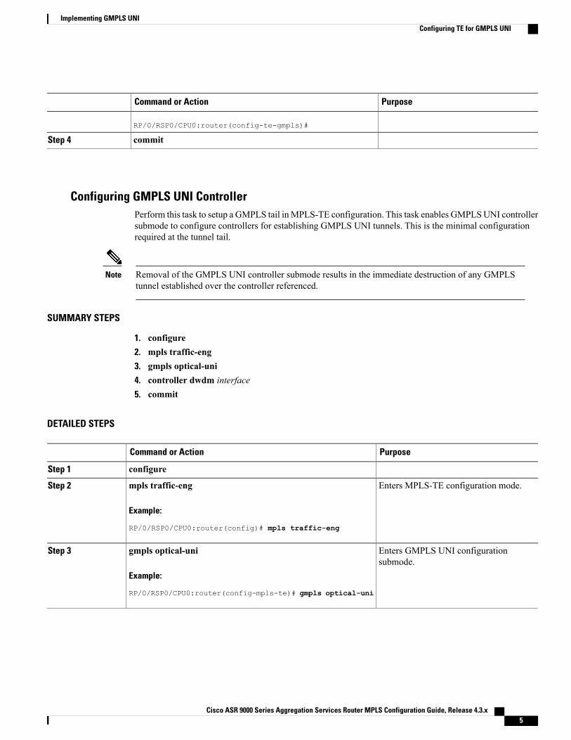
Configuring GMPLS UNI ControllerPerform this task to setup a GMPLS tail inMPLS-TE configuration. This task enables GMPLSUNI controllersubmode to configure controllers for establishing GMPLS UNI tunnels. This is the minimal configurationrequired at the tunnel tail.
Removal of the GMPLS UNI controller submode results in the immediate destruction of any GMPLStunnel established over the controller referenced.
Note
SUMMARY STEPS
1. configure2. mpls traffic-eng3. gmpls optical-uni4. controller dwdm interface5. commit
DETAILED STEPS
PurposeCommand or Action
configureStep 1
Enters MPLS-TE configuration mode.mpls traffic-eng
Example:
RP/0/RSP0/CPU0:router(config)# mpls traffic-eng
Step 2
Enters GMPLS UNI configurationsubmode.
gmpls optical-uni
Example:
RP/0/RSP0/CPU0:router(config-mpls-te)# gmpls optical-uni
Step 3
Cisco ASR 9000 Series Aggregation Services Router MPLS Configuration Guide, Release 4.3.x 5
Implementing GMPLS UNIConfiguring TE for GMPLS UNI

PurposeCommand or Action
Enters GMPLS UNI controller submode.controller dwdm interface
Example:
RP/0/RSP0/CPU0:router(config-te-gmpls)# controller dwdm
Step 4
0/1/0/1
RP/0/RSP0/CPU0:router(config-te-gmpls-cntl)#
commitStep 5
Configuring GMPLS UNI Controller as a Tunnel HeadPerform this task to configure the tunnel properties for a GMPLS UNI controller.
This configuration designates the controller as a tunnel-head, rather than a tunnel tail. After the tunnel propertiesare configured, the incoming path messages are rejected and any existing tail-end tunnel is torn down.
SUMMARY STEPS
1. configure2. mpls traffic-eng3. gmpls optical-uni4. controller dwdm interface5. tunnel-properties6. tunnel-id number7. destination ipv4 unicast address8. path-option 10 no-ero lockdown9. commit
DETAILED STEPS
PurposeCommand or Action
configureStep 1
Enters MPLS-TE configuration mode.mpls traffic-eng
Example:
RP/0/RSP0/CPU0:router(config)# mpls traffic-eng
Step 2
Cisco ASR 9000 Series Aggregation Services Router MPLS Configuration Guide, Release 4.3.x6
Implementing GMPLS UNIConfiguring TE for GMPLS UNI

PurposeCommand or Action
Enters GMPLS UNI configuration submode.gmpls optical-uni
Example:
RP/0/RSP0/CPU0:router(config-mpls-te)# gmplsoptical-uni
Step 3
Enters GMPLS UNI controller submode.controller dwdm interface
Example:
RP/0/RSP0/CPU0:router(config-te-gmpls)# controller
Step 4
dwdm 0/1/0/1
RP/0/RSP0/CPU0:router(config-te-gmpls-cntl)#
Enters the submode to configure tunnel-specificinformation for a GMPLS UNI controller.
tunnel-properties
Example:
RP/0/RSP0/CPU0:router(config-te-gmpls-cntl)#
Step 5
tunnel-properties
RP/0/RSP0/CPU0:router(config-te-gmpls-tun)#
Specifies a tunnel-id for a headend router of a GMPLStunnel. The tunnel-id is a 16-bit number ranging from0 to 65535.
tunnel-id number
Example:
RP/0/RSP0/CPU0:router(config-te-gmpls-tun)#tunnel-id 100
Step 6
Specifies a tunnel destination for a headend router ofa GMPLS tunnel. The destination argument is an IPv4address.
destination ipv4 unicast address
Example:
RP/0/RSP0/CPU0:router(config-te-gmpls-tun)#destination ipv4 unicast 10.10.3.4
Step 7
Specifies the path-option for a headend router of aGMPLS tunnel.
path-option 10 no-ero lockdown
Example:
RP/0/RSP0/CPU0:router(config-te-gmpls-tun)#path-option 10 no-ero lockdown
Step 8
An XRO attribute-set can be specified as partof the path-option, if required.
Note
commitStep 9
Configuring Other Tunnel Properties for a GMPLS UNI TunnelPerform this task to configure the optional tunnel properties for a GMPLS UNI tunnel. This configuration isoptional, and if omitted, the GMPLS tunnel is established with the default property values.
Cisco ASR 9000 Series Aggregation Services Router MPLS Configuration Guide, Release 4.3.x 7
Implementing GMPLS UNIConfiguring TE for GMPLS UNI

SUMMARY STEPS
1. configure2. mpls traffic-eng3. gmpls optical-uni4. controller dwdm interface5. tunnel-properties6. priority setup-priority hold-priority7. record-route8. signalled-name name9. logging events lsp-status state10. commit
DETAILED STEPS
PurposeCommand or Action
configureStep 1
Enters MPLS-TE configuration mode.mpls traffic-eng
Example:
RP/0/RSP0/CPU0:router(config)# mpls
Step 2
traffic-eng
Enters GMPLS UNI configuration submode.gmpls optical-uni
Example:
RP/0/RSP0/CPU0:router(config-mpls-te)# gmplsoptical-uni
Step 3
Enters GMPLS UNI controller submode.controller dwdm interface
Example:
RP/0/RSP0/CPU0:router(config-te-gmpls)#controller dwdm 0/1/0/1
Step 4
Enters the submode to configure tunnel-specific informationfor a GMPLS UNI controller.
tunnel-properties
Example:
RP/0/RSP0/CPU0:router(config-te-gmpls-cntl)#tunnel-properties
Step 5
Specifies the priority for a GMPLS tunnel. The default priorityvalue is 7 for both setup and hold priorities.
priority setup-priority hold-priority
Example:
RP/0/RSP0/CPU0:router(config-te-gmpls-tun)#priority 3 2
Step 6
Cisco ASR 9000 Series Aggregation Services Router MPLS Configuration Guide, Release 4.3.x8
Implementing GMPLS UNIConfiguring TE for GMPLS UNI

PurposeCommand or Action
The setup-priority and hold-priority values arenumbers ranging from 0 to 7, where 0 represents thehighest priority. The hold-priority must be equal orhigher (numerically less) than the setup-priority.
Note
Enables record-route functionality for a GMPLS tunnel.record-route
Example:
RP/0/RSP0/CPU0:router(config-te-gmpls-tun)#record-route
Step 7
Configures signalled-name for a GMPLS tunnel.signalled-name nameStep 8
Example:
RP/0/RSP0/CPU0:router(config-te-gmpls-tun)#signalled-name sign1
If no signalled name is configured, TE will generatea default name in the form ofrouter-name_tunnel-id_destination-address, forexample, te-ma1_123_10.10.10.10.
Note
Configure events to generate system log messages when statechanges occur on the GMPLS tunnel. If omitted, no eventswill result in the generation of system log messages.
logging events lsp-status state
Example:
RP/0/RSP0/CPU0:router(config-te-gmpls-tun)#logging events lsp-status state
Step 9
commitStep 10
Configuring LSP DiversityTo configure an XRO attribute-set as part of the path-option for MPLS-TE, and to specify exclusions for anattribute set for LSP diversity, follow these procedures:
Configuring XRO Attribute-set
Perform this task to configure XRO attribute set in the GMPLS UNI tunnel path-option, under MPLS-TEsubmode.
SUMMARY STEPS
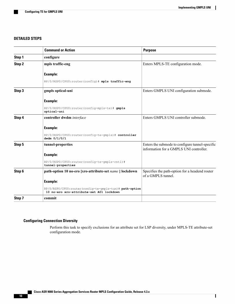
1. configure2. mpls traffic-eng3. gmpls optical-uni4. controller dwdm interface5. tunnel-properties6. path-option 10 no-ero [xro-attribute-set name ] lockdown7. commit
Cisco ASR 9000 Series Aggregation Services Router MPLS Configuration Guide, Release 4.3.x 9
Implementing GMPLS UNIConfiguring TE for GMPLS UNI
DETAILED STEPS
PurposeCommand or Action
configureStep 1
Enters MPLS-TE configuration mode.mpls traffic-eng
Example:
RP/0/RSP0/CPU0:router(config)# mpls traffic-eng
Step 2
Enters GMPLS UNI configuration submode.gmpls optical-uni
Example:
RP/0/RSP0/CPU0:router(config-mpls-te)# gmplsoptical-uni
Step 3
Enters GMPLS UNI controller submode.controller dwdm interface
Example:
RP/0/RSP0/CPU0:router(config-te-gmpls)# controllerdwdm 0/1/0/1
Step 4
Enters the submode to configure tunnel-specificinformation for a GMPLS UNI controller.
tunnel-properties
Example:
RP/0/RSP0/CPU0:router(config-te-gmpls-cntl)#tunnel-properties
Step 5
Specifies the path-option for a headend routerof a GMPLS tunnel.
path-option 10 no-ero [xro-attribute-set name ] lockdown
Example:
RP/0/RSP0/CPU0:router(config-te-gmpls-tun)# path-option10 no-ero xro-attribute-set A01 lockdown
Step 6
commitStep 7
Configuring Connection Diversity
Perform this task to specify exclusions for an attribute set for LSP diversity, under MPLS-TE attribute-setconfiguration mode.
Cisco ASR 9000 Series Aggregation Services Router MPLS Configuration Guide, Release 4.3.x10
Implementing GMPLS UNIConfiguring TE for GMPLS UNI

SUMMARY STEPS
1. configure2. mpls traffic-eng3. attribute-set xro name4. exclude {best-effort | strict} lsp source source-address destination destination-address tunnel-id
tunnel-id extended-tunnel-id extended-tunnel-id [lsp-id lsp-id]5. commit
DETAILED STEPS
PurposeCommand or Action
configureStep 1
Enters MPLS-TE configuration mode.mpls traffic-eng
Example:
RP/0/RSP0/CPU0:router(config)# mpls traffic-eng
Step 2
Configures an XRO attribute-set for aGMPLS tunnel.
attribute-set xro name
Example:
RP/0/RSP0/CPU0:router(config-mpls-te)# attribute-set xroattrset01
Step 3
Specifies exclusions for an attribute set forLSP diversity.
exclude {best-effort | strict} lsp source source-address destinationdestination-address tunnel-id tunnel-id extended-tunnel-idextended-tunnel-id [lsp-id lsp-id]
Step 4
A maximum of 20 LSP exclusionsper XRO is supported.
Note
Example:
RP/0/RSP0/CPU0:router(config-te-attribute-set)# excludebest-effort lsp source 10.10.1.2 destination 10.20.4.4tunnel-id 17 extended-tunnel-id 10.20.3.3 lsp-id 17RP/0/RSP0/CPU0:router(config-te-attribute-set)#
commitStep 5
Configuring LMP for GMPLS UNITo implement LMP configuration for GMPLS UNI, follow these procedures:
Configuring Optical Router IDPerform this task to enable GMPLS UNI LMP functionality and to configure LMP unicast router ID.
Cisco ASR 9000 Series Aggregation Services Router MPLS Configuration Guide, Release 4.3.x 11
Implementing GMPLS UNIConfiguring LMP for GMPLS UNI

SUMMARY STEPS
1. configure2. lmp3. gmpls optical-uni4. router-id ipv4 unicast address5. commit
DETAILED STEPS
PurposeCommand or Action
configureStep 1
Enters LMP configuration mode.lmp
Example:
RP/0/RSP0/CPU0:router(config)# lmp
Step 2
Enters GMPLS UNI configuration submode.gmpls optical-uni
Example:
RP/0/RSP0/CPU0:router(config-lmp)# gmpls optical-uni
Step 3
Configures the LMP unicast router ID forGMPLS.
router-id ipv4 unicast address
Example:
RP/0/RSP0/CPU0:router(config-lmp-gmpls-uni)# router-id
Step 4
ipv4 unicast 10.10.4.4
commitStep 5
Configuring an LMP NeighborPerform this task to configure an LMP neighbor for a GMPLS UNI tunnel.
Cisco ASR 9000 Series Aggregation Services Router MPLS Configuration Guide, Release 4.3.x12
Implementing GMPLS UNIConfiguring LMP for GMPLS UNI

SUMMARY STEPS
1. configure2. lmp3. gmpls optical-uni4. neighbor name5. ipcc routed6. router-id ipv4 unicast address7. commit
DETAILED STEPS
PurposeCommand or Action
configureStep 1
Enters LMP configuration mode.lmp
Example:
RP/0/RSP0/CPU0:router(config)# lmp
Step 2
Enters GMPLS UNI configuration submode.gmpls optical-uni
Example:
RP/0/RSP0/CPU0:router(config-lmp)# gmpls optical-uni
Step 3
Specifies an LMP neighbor for GMPLS andenters LMPGMPLSUNI neighbor configurationsubmode.
neighbor name
Example:
RP/0/RSP0/CPU0:router(config-lmp-gmpls-uni)# neighbor
Step 4
nbr1
Specifies the LMP neighbor IPCC configurationfor GMPLS UNI.
ipcc routed
Example:
RP/0/RSP0/CPU0:router(config-lmp-gmpls-uni-nbr-nbr1)#
Step 5
ipcc routed
Configures the LMP unicast router ID forGMPLS.
router-id ipv4 unicast address
Example:
RP/0/RSP0/CPU0:router(config-lmp-gmpls-uni-nbr-nbr1)#
Step 6
router-id ipv4 unicast 10.10.4.4
commitStep 7
Cisco ASR 9000 Series Aggregation Services Router MPLS Configuration Guide, Release 4.3.x 13
Implementing GMPLS UNIConfiguring LMP for GMPLS UNI
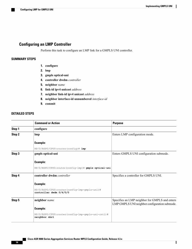
Configuring an LMP ControllerPerform this task to configure an LMP link for a GMPLS UNI controller.
SUMMARY STEPS
1. configure2. lmp3. gmpls optical-uni4. controller dwdm controller5. neighbor name6. link-id ipv4 unicast address7. neighbor link-id ipv4 unicast address8. neighbor interface-id unnumbered interface-id9. commit
DETAILED STEPS
PurposeCommand or Action
configureStep 1
Enters LMP configuration mode.lmp
Example:
RP/0/RSP0/CPU0:router(config)# lmp
Step 2
Enters GMPLS UNI configuration submode.gmpls optical-uni
Example:
RP/0/RSP0/CPU0:router(config-lmp)# gmpls optical-uni
Step 3
Specifies a controller for GMPLS UNI.controller dwdm controller
Example:
RP/0/RSP0/CPU0:router(config-lmp-gmpls-uni)#
Step 4
controller dwdm 0/4/0/0
Specifies an LMP neighbor for GMPLS and entersLMPGMPLSUNI neighbor configuration submode.
neighbor name
Example:
RP/0/RSP0/CPU0:router(config-lmp-gmpls-uni-cntl)#
Step 5
neighbor nbr1
Cisco ASR 9000 Series Aggregation Services Router MPLS Configuration Guide, Release 4.3.x14
Implementing GMPLS UNIConfiguring LMP for GMPLS UNI

PurposeCommand or Action
Specifies the optical interface address for an LMPlink for a GMPLS UNI controller.
link-id ipv4 unicast address
Example:
RP/0/RSP0/CPU0:router(config-lmp-gmpls-uni-cntl)#
Step 6
link-id ipv4 unicast 10.2.2.4
Specifies the neighbor's optical address of an LMPlink for a GMPLS UNI controller.
neighbor link-id ipv4 unicast address
Example:
RP/0/RSP0/CPU0:router(config-lmp-gmpls-uni-cntl)#
Step 7
neighbor link-id ipv4 unicast 10.10.4.4
Specifies the neighbor's optical interface ID of anLMP link for a GMPLS UNI controller.
neighbor interface-id unnumbered interface-id
Example:
RP/0/RSP0/CPU0:router(config-lmp-gmpls-uni-cntl)#
Step 8
neighbor interface-id unnumbered 17
commitStep 9
Configuring RSVP Optical Refresh Interval and Missed CountPerform this task to configure optical refresh interval under the RSVP controller submode and to configurethe number of missed refresh messages allowed before optical tunnel states are deleted.
SUMMARY STEPS
1. configure2. rsvp3. controller dwdm interface4. signalling refresh out-of-band interval interval5. signalling refresh out-of-band missed miss-count6. commit
DETAILED STEPS
PurposeCommand or Action
configureStep 1
Cisco ASR 9000 Series Aggregation Services Router MPLS Configuration Guide, Release 4.3.x 15
Implementing GMPLS UNIConfiguring RSVP Optical Refresh Interval and Missed Count

PurposeCommand or Action
Enters RSVP configuration mode.rsvp
Example:
RP/0/RSP0/CPU0:router(config)# rsvp
Step 2
Configures a controller for establishing a GMPLS UNI tunnel.controller dwdm interface
Example:
RP/0/RSP0/CPU0:router(config-rsvp)#
Step 3
controller dwdm 0/1/0/1
Configures optical refresh interval.signalling refresh out-of-band interval intervalStep 4
Example:
RP/0/RSP0/CPU0:router(config-rsvp-cntl)#
The interval argument is the interval (in seconds) at whichrefresh messages are sent and expected to be received. Therange is 180 to 86400 (a refresh-interval of 1 day).
signalling refresh out-of-band interval 200
Configures number of missed refresh messages allowed beforeoptical tunnel states are deleted.
signalling refresh out-of-band missed miss-count
Example:
RP/0/RSP0/CPU0:router(config-rsvp-cntl)#
Step 5
The miss-count argument is the number of refresh messages,expected at the configured refresh-interval, which can bemissedbefore optical tunnel states time out. The accepted range is 1to 48. The default value is 12.
signalling refresh out-of-band missed 30
commitStep 6
Configuration Examples for GMPLS UNIThese configuration examples are provided for GMPLS UNI:
Configuring Head UNI-C for a GMPLS Tunnel: ExampleThis example shows the minimal head UNI-C configuration require to establish a GMPLS tunnel:
rsvpcontroller dwdm 0/1/0/1signalling refresh out-of-band interval 3600signalling refresh out-of-band missed 24
!!mpls traffic-enggmpls optical-unicontroller dwdm 0/1/0/1tunnel-propertiestunnel-id 100
Cisco ASR 9000 Series Aggregation Services Router MPLS Configuration Guide, Release 4.3.x16
Implementing GMPLS UNIConfiguration Examples for GMPLS UNI

destination 100.20.20.20path-option 10 no-ero
!!
!!lmpgmpls optical-unirouter-id 100.11.11.11neighbor nbr_Aipcc routedneighbor router-id ipv4 unicast 100.12.12.12
!controller dwdm 0/1/0/1neighbor nbr_Alink-id ipv4 unicast 192.168.100.1neighbor link-id ipv4 unicast 192.168.100.2neighbor interface-id unnumbered 13
!!
!
Configuring Tail UNI-C for a GMPLS Tunnel: ExampleThis example shows the minimal tail UNI-C configuration require to establish a GMPLS tunnel:
The controller must be specified under the GMPLS UNI submode to inform TE that incoming GMPLSpath messages are to be accepted and processed.
Note
rsvpcontroller dwdm 0/1/0/1signalling refresh out-of-band interval 3600signalling refresh out-of-band missed 24
!!mpls traffic-enggmpls optical-unicontroller dwdm 0/1/0/1!
!!lmpgmpls optical-unirouter-id 100.20.20.20neighbor nbr_Bipcc routedneighbor router-id ipv4 unicast 100.19.19.19
!controller dwdm 0/1/0/1neighbor nbr_Blink-id ipv4 unicast 192.168.103.2neighbor link-id ipv4 unicast 192.168.103.1neighbor interface-id unnumbered 22
!!
!
Cisco ASR 9000 Series Aggregation Services Router MPLS Configuration Guide, Release 4.3.x 17
Implementing GMPLS UNIConfiguring Tail UNI-C for a GMPLS Tunnel: Example

Configuring LSP Diversity: ExampleThis example shows the configuration for two diverse LSPs:
mpls traffic-engattribute-set xro exclude-tun1exclude best-effort lsp source 88.0.0.8 destination 10.0.0.2 tunnel-id 1
extended-tunnel-id 88.0.0.8!attribute-set xro exclude-tun2exclude strict lsp source 88.0.0.8 destination 10.0.1.2 tunnel-id 2 extended-tunnel-id
88.0.0.8 lsp-id 2!gmpls optical-unicontroller dwdm 0/1/0/0tunnel-propertieslogging events lsp-status statetunnel-id 1destination ipv4 unicast 10.0.0.2path-option 10 no-ero xro-attribute-set exclude-tun2!!controller dwdm 0/1/0/1tunnel-propertieslogging events lsp-status statetunnel-id 2destination ipv4 unicast 10.0.1.2path-option 10 no-ero xro-attribute-set exclude-tun1!!!!
Additional ReferencesFor additional information related to implementing GMPLS UNI, refer to the following references:
Related Documents
Document TitleRelated Topic
GMPLS UNI Commandsmodule in Cisco ASR 9000Series Aggregation Services RouterMPLS CommandReference
GMPLS UNI commands
MPLS Traffic Engineering commands module inCisco ASR 9000 Series Aggregation Services RouterMPLS Command Reference
MPLS Traffic Engineering commands
RSVP commands module in Cisco ASR 9000 SeriesAggregation Services Router MPLS CommandReference
RSVP commands
Cisco ASR 9000 Series Aggregation Services RouterGetting Started Guide
Getting started material
Cisco ASR 9000 Series Aggregation Services Router MPLS Configuration Guide, Release 4.3.x18
Implementing GMPLS UNIConfiguring LSP Diversity: Example

Document TitleRelated Topic
Configuring AAA Servicesmodule in Cisco ASR 9000Series Aggregation Services Router System SecurityConfiguration Guide
Information about user groups and task IDs
Standards
TitleStandard
—No new or modified standards are supported by thisfeature, and support for existing standards has notbeen modified by this feature.
MIBs
MIBs LinkMIBs
To locate and download MIBs using Cisco IOS XRsoftware, use the Cisco MIB Locator found at thefollowingURL and choose a platform under the CiscoAccess Products menu:
http://cisco.com/public/sw-center/netmgmt/cmtk/mibs.shtml
—
RFCs
TitleRFCs
Generalized Multi-Protocol Label Switching(GMPLS) Signaling Functional Description
RFC 3471
Generalized Multi-Protocol Label Switching(GMPLS) Signaling Resource ReserVationProtocol-Traffic Engineering (RSVP-TE) Extensions
RFC 3473
GeneralizedMultiprotocol Label Switching (GMPLS)User-Network Interface (UNI): Resource ReserVationProtocol-Traffic Engineering (RSVP-TE) Support forthe Overlay Model
RFC 4208
RSVP-TE Extensions in Support of End-to-EndGeneralized Multi-Protocol Label Switching(GMPLS) Recovery
RFC 4872
Cisco ASR 9000 Series Aggregation Services Router MPLS Configuration Guide, Release 4.3.x 19
Implementing GMPLS UNIAdditional References

TitleRFCs
Exclude Routes - Extension to Resource ReserVationProtocol-Traffic Engineering (RSVP-TE)
RFC 4874
Generalized Labels for Lambda-Switch-Capable(LSC) Label Switching Routers
RFC 6205
Technical Assistance
LinkDescription
http://www.cisco.com/techsupportThe Cisco Technical Support website containsthousands of pages of searchable technical content,including links to products, technologies, solutions,technical tips, and tools. Registered Cisco.com userscan log in from this page to access evenmore content.
Cisco ASR 9000 Series Aggregation Services Router MPLS Configuration Guide, Release 4.3.x20
Implementing GMPLS UNIAdditional References