implementing adaptive modulation in a software-defined cognitive radio brandon bilinski computer...
TRANSCRIPT

Implementing Adaptive Modulation in a Software-Defined Cognitive Radio
Brandon BilinskiComputer Engineering Senior, Clemson University

What is a Software-Defined Radio?
An SDR is a flexible radio where programmable hardware is controlled by software.
SDRs can tune to any frequency band or change to any modulation type.
I am employing adaptive modulation.

Previous Implementations
With the frequency bands getting more and more crowded, a solution is needed.
Software-Defined radios allow for the advent of cognitive radios.
Many cognitive radios sense busy channels and change to free channels
What if there are no free channels available to change between?

Why adapt modulations?
If a channel is noisy it is more beneficial to change modulations rather than adjust power.
The following modulation types had constant power and bandwidth.

First Steps of Adaptive Modulation
Construct a library of various modulation types in the FPGA chip.
My radio contains 32-ary Orthogonal, BPSK, QPSK, and 16-QAM
All modulation types designed in Simulink using the Xilinx FPGA blockset.
BPSK – Binary Phase Shift Keying QPSK – Quadrature Phase Shift Keying QAM – Quadrature Amplitude Modulation

32-ary Orthogonal Modulation
This is the most robust modulation scheme used in my radio.
This scheme uses 32 chips to represent 5 bits of data, so it is also the slowest.
Each signal is orthogonal as a result of the orthogonality of the Hadamard matrix.

What are Hadamard Matrices?
21 1
1 1H
A Hadamard matrix is a matrix of the form 2^(n-1) x 2^(n-1) where every row is orthogonal.
If you multiply the Hadamard matrix by the transpose of any row, you will get n in the appropriate row and 0s elsewhere.
1 1 2* 1 1
1 1 0T

32-ary Orthogonal Implementation

32-ary Orthogonal Modulation Cont.
Transmit two words: 00000 and 00001 Corresponding Hadamard Rows:1 1 1 1 1 1 1 1 1 1 1 1 1 1 1 1 1 1 1 1 1 1 1 1 1 1 1 1 1 1 1 1
1 -1 1 -1 1 -1 1 -1 1 -1 1 -1 1 -1 1 -1 1 -1 1 -1 1 -1 1 -1 1 -1 1 -1 1 -1 1 -1

BPSK Modulation
The transmitter modulates only one bit at a time.
A ‘0’ is mapped to -1*cosine while a ‘1’ is mapped to 1*cosine.
The BPSK constellation is mapped on the complex plane to the right:

BPSK Implementation

BPSK Modulation Cont.
Transmit the following bits: 11110101

QPSK Modulation
QPSK is less robust than BPSK, but it can send twice the bits in one transmission.
QPSK has four possible words: ’00’, ’01’, ’10’, ’11’ that are modulated using a combination of sine and cosine.
The constellation mapping is once
again shown on the right:

QPSK Implementation

QPSK Modulation Cont.
Transmit the following bits: 11011000

16-QAM Modulation
Unlike BPSK and QPSK, 16-QAM involves changes in phase and amplitude.
In this way, each word can be 4 bits long, which allows you to send twice the bits that are possible with QPSK.
This is the toughest scheme that I implement to demodulate due to close proximity of points in the constellation.
d3- 0: cosine is negative
1: cosine is positive
d2- 0: 1x cosine
1: 2x cosine d1- 0: sine is
negative
1: sine is positive
d0- 0: 1x sine
1: 2x sine

16-QAM Implementation

How do you get environment stats?
How do you know what the CENR is in the environment in order to adapt your modulation types?

Adapting 32-Orthogonal Modulation
As previously stated, multiplying an nxn Hadamard matrix by a transpose of one row of the matrix theoretically results in an nx1 matrix of n and all 0s.
To estimate the signal to noise ratio we can use the following equation: 1 – (second_largest/max_product)
The following example is for 4-ary modulation:
1 1 1 1 .1
1 1 1 1 .7* 1.2 .7 .9 1.1
1 1 1 1 3.9
1 1 1 1 .3
T
1 - (.7/3.9) = .821

32-ary Ratio Statistic
When the ratio gets above .38, then it is desirable to switch to BPSK.
With additional orthogonal schemes included, a ratio lower than .38 would signify a switch to 16-ary orthogonal.
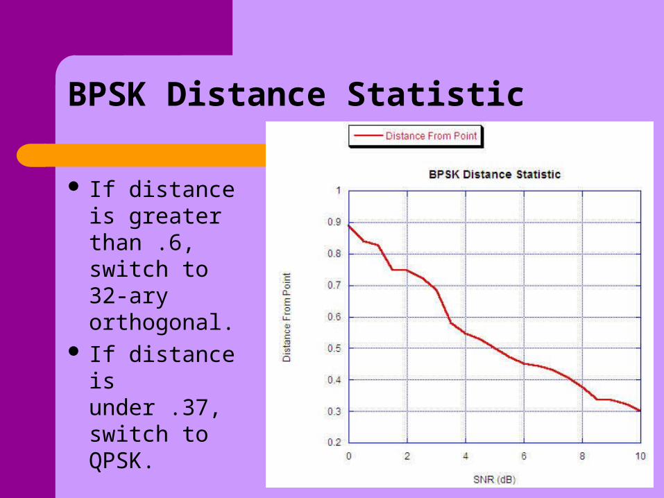
BPSK Distance Statistic
If distance is greater than .6, switch to 32-ary orthogonal.
If distance is under .37, switch to QPSK.

QPSK Distance Statistic
If distance is greater than .37, switch to BPSK
If distance is less than .19, switch to 16-QAM

16-QAM Distance Statistic
If the distance is greater than .19, switch down to QPSK.

Future Plans
Finish 16-QAM demodulator and add timing and phase synchronization in all demodulators.
Implement modulation library in FPGA Enable modulation scheme switching by
programming the DSP chip in the radio. Move the radio through different noise
environments to ensure modulation switching occurs where expected.
Add Forward Error Correcting codes to improve robustness of system.

Acknowledgements
Faculty Advisor: Dr. Michael Pursley
Graduate Student Advisors: Joel Simoneau Tommy Royster
Dr. Noneaker, Dr. Xu and Josh LawrenceDr. Russell, Dr. Hubing, Dr. Baum, Dr.
Hubbard and Dr. Fishman.

Questions?
Brandon BilinskiComputer Engineering Senior, Clemson University