implementing a microsoft private cloud on hp virtualsystem with microsoft system center 2012
TRANSCRIPT
Technical white paper
Implementing a Microsoft private cloud on HP VirtualSystem with Microsoft System Center 2012
Table of contents
Executive summary 3
Introduction 3
Overview of HP VirtualSystem 3
HP VirtualSystem offerings 4
Private cloud components 4
VirtualSystem hardware 5
VirtualSystem software 8
Building a private cloud with SC2012 VMM 11
Software versions used 11
Prerequisites 11
Creating logical networks 13
Deploying Hyper-V hosts 16
Configuring networks on Hyper-V hosts 25
Configuring storage for Hyper-V hosts 32
Building a Hyper-V cluster 34
Deploying virtual machines 36
Monitoring a private cloud with SC2012 Operations Manager 36
Adding Hyper-V hosts to the Operations console 37
Configuring OM connections to VMM 37
Installing IC-SC 38
Installing HP Storage Management Pack for System Center 41
Automating the private cloud with System Center 2012 Orchestrator 44
Deploying integration packs 44
Configuring SC Orchestrator connections 45

2
Automating the deployment of a new server 47
Summary 57
Appendix A 58
Disclaimer of warranty 58
Contents 58
For more information 64
3
Executive summary
For a growing number of companies, the journey to cloud computing starts with a private cloud – a service-based infrastructure that is implemented at their own premises. IT resources are pooled in a private cloud, allowing services to be rapidly deployed or modified in response to changing business needs. A private cloud also includes a centralized, automated, and integrated set of tools to provide consistent management for the underlying physical and virtual environments.
HP VirtualSystem, Microsoft® Windows® Server 2008 R2, Hyper-V, and Microsoft System Center 2012 (System Center) are key components of the solution described in this paper, allowing you to build a scalable, efficient private cloud environment that can transform the way you deliver IT services to the business.
This white paper provides guidelines for configuring a private cloud infrastructure based on HP VirtualSystem and System Center. It also details the steps required to build a resilient Hyper-V environment for the cloud and then configure the management framework needed to monitor cloud services and scale up the infrastructure as needed.
Target audience: The audience for this document is intended to be technical, including IT architects, HP and HP Partner services personnel, implementation specialists and IT planners.
Introduction
The private cloud infrastructure provides a new model for delivering and consuming IT services within the enterprise. It requires a fundamental shift in the way that data centers and IT processes are designed, allowing you to move away from traditional resource silos towards a more efficient, dynamic design.
Private cloud architecture includes the following key characteristics:
Pools of IT resources that can be allocated when business units request infrastructure or application services, allowing you to respond to changing business needs in a matter of hours or days, rather than the weeks or months required by a conventional infrastructure
A focus on demand, supply, and delivery rather than a built-to-order solution
Implementing the private cloud model requires a change in IT strategy, investment, and management, moving from a reactive, tool-centric model of resource management to a proactive model that uses streamlined processes and automation. To achieve this vision, IT must shift its focus from assembling hardware components and installing software to building a resilient, centralized infrastructure of available resources – both physical and virtual – that can be provisioned on-demand. All resources – including hardware, software, and applications – needed to support a particular service are provisioned on-demand in real time via intelligent resource management tools, making the process both scalable and flexible.
To accelerate your journey to the cloud, HP VirtualSystem for Microsoft provides a factory-integrated, turnkey virtualization solution based on Microsoft Hyper-V. This solution leverages System Center to create a management framework for the Microsoft private cloud.
Overview of HP VirtualSystem
A VirtualSystem solution is essentially composed of the following hardware elements:
Compute nodes
Storage nodes
Management nodes
Network switches
These elements have been chosen and sized based on industry best practices designs to deliver a range of resource-balanced solution capacities which are highly available (HA) and compliant with the Microsoft Private Cloud Fast Track architecture. The hardware is factory integrated, then the software is installed and the solution deployed and integrated in your own environment.
4
Compute nodes are physical servers that host your workloads as virtual machines (VMs). Since these servers exclusively run a hypervisor operating system, no workload or applications should be deployed directly on the physical machines.
Storage nodes are SAN-based storage arrays that are shared by compute nodes. As a recommended practice, application data and the binary files for workloads should be stored on the SAN arrays. While data can also be hosted on the local disks of compute nodes, this is not recommended.
Management nodes are dedicated servers that host management applications for the VirtualSystem solution. In the same way as compute nodes, management nodes run a hypervisor, with management software contained in VMs. Using separate VMs for management software prevents resource conflicts that could occur if such applications were co-hosted with your workloads.
Network switches connect all the components together, creating both private and public-facing networks. Private networks provide internal connectivity, such as the communications network for Hyper-V cluster nodes; public networks connect servers and VMs to the external production network environment.
VirtualSystem solutions use off-the-shelf components both for hardware and software. You can buy these components today and build a solution yourself using the reference architecture and solution guides that HP plans to publish. A self-build solution offers several advantages; for example, you can select the components needed and re-purpose existing hardware for the new solution. This approach offers great flexibility in component selection and can also reduce the total cost of acquiring solution hardware; on the other hand, it may require a significant amount of time and labor to assemble the hardware, cable components, and install and configure the software environment.
To reduce complexity and accelerate the deployment process, HP offers end-to-end VirtualSystem solutions with hardware components that have been tested, assembled, and pre-configured at the factory before being shipped to you. HP Services engineers work with you on-site to deploy the software stack on the VirtualSystem solution. As a result, you get a functional, managed virtualization infrastructure and can start to migrate your workloads on to the platform.
HP VirtualSystem offerings
HP offers the following HP VirtualSystem solutions for Microsoft Hyper-V:
VirtualSystem VS1, with HP ProLiant DL servers and HP LeftHand P4500 SAN storage
VirtualSystem VS2, with HP ProLiant BL server blades and HP LeftHand P4800 SAN storage
VirtualSystem VS3, with HP ProLiant BL server blades and HP 3PAR storage
Each solution has multiple versions. A base configuration offers an entry price point for VirtualSystem, with the fewest compute nodes and lowest storage capacity, while midline and extended configurations maximize rack real estate and enable the scale-up of resources. You can simply add new compute nodes when needed since the solution is built with upgrade-ready power and the networking needed to support additional components.
For more details on VirtualSystem, visit http://www.hp.com/go/virtualsystem.
Private cloud components
The document details implementing a Microsoft private cloud with System Center 2012 using an HP VirtualSystem VS2 base configuration hardware as the reference architecture. The hardware and software components detailed in this document are identical to VirtualSystem VS2 v1, with the exception of Microsoft System Center version. In version 1 of VirtualSystem VS2, Microsoft System Center 2008 R2 is deployed. This document leverages the System Center 2012 release candidate version for implementing the Microsoft private cloud.
To understand this implementation, it is helpful to be familiar with various components of the VirtualSystem VS2 solution, as described in this section.
5
VirtualSystem hardware
VirtualSystem VS2 includes the following HP hardware:
HP BladeSystem c7000 enclosure
HP ProLiant BL-series server blades
HP ProLiant DL-series servers
HP LeftHand P4800 G2 SAN
HP 5800-series and 5820-series network switches
c7000 enclosure
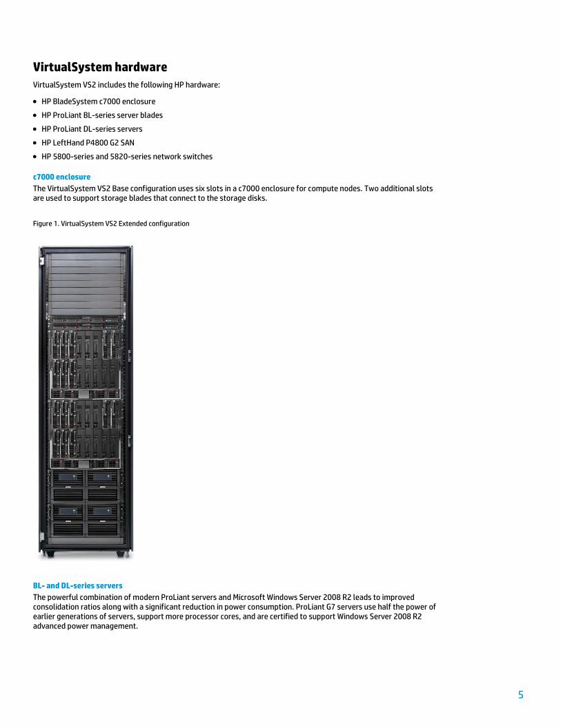
The VirtualSystem VS2 Base configuration uses six slots in a c7000 enclosure for compute nodes. Two additional slots are used to support storage blades that connect to the storage disks.
Figure 1. VirtualSystem VS2 Extended configuration
BL- and DL-series servers
The powerful combination of modern ProLiant servers and Microsoft Windows Server 2008 R2 leads to improved consolidation ratios along with a significant reduction in power consumption. ProLiant G7 servers use half the power of earlier generations of servers, support more processor cores, and are certified to support Windows Server 2008 R2 advanced power management.

6
BL460c G7 (workload) and DL360 G7 (management) servers make ideal platforms for a private cloud environment, delivering features that include:
Intel® Xeon® 5600 series processors
Intel Virtualization Technology (Intel VT)
Support for CPU core parking, which allows Windows and Hyper-V R2 (the hypervisor; hereafter referred to as Hyper-V in this document) to consolidate processing on to the fewest possible processor cores and suspend inactive cores
Maximum memory configuration of 192 GB
Wide variety of I/O options
Multiple options for network connectivity
HP Integrated Lights-Out (iLO) management
Broad range of options for providing redundancy
Embedded RAID controller
The Intel Xeon processors deployed in BL460c G7 and DL360 G7 servers provide features that can optimize Hyper-V execution; for example, Intel VT offers hardware assistance for virtualization. In addition, second-level address translation (SLAT) capability reduces hypervisor processor time and saves about 1 MB of memory per VM by using the processor to perform VM memory management functions. Delegating functionality to the processor leads to enhanced scalability and performance.
Running exclusively on 64-bit processors, Windows Server 2008 R2 delivers enhanced support for physical processor and memory resources; for example, up to 8 x64 physical processors (up to 256 logical processors) can now be supported on a single server. This operating system also increases support for virtual processor resources, allowing Hyper-V to support up to 64 logical processors (cores or Hyper-Threaded CPUs).
P4800 G2 SAN
An integral component of the VS2 solution is the HP LeftHand P4800 G2 SAS BladeSystem (P4800 G2) SAN, which provides scalable, shared storage for a converged server, storage, and networking environment.
The VS2 base configuration provides 42 TB of storage capacity via two P4460sb storage blades connected to 70 disk drives, while the extended configuration can deliver up to 84 TB of storage capacity via four storage blades and 140 disk drives.
Installed in the c7000 enclosure, storage blades run SAN/iQ software to provide SAN controller functionality, supporting high levels of SAN scalability and data availability.
Fully transparent to Hyper-V, the iSCSI-based P4800 G2 SAN provides high availability without the need for additional synchronous replication software. Moreover, Network RAID, which mirrors data blocks across storage nodes in the SAN, can be combined with traditional hardware RAID to extend fault tolerance to new levels. With Network RAID, you can create up to four copies of the data, providing a level of protection that allows the SAN to survive the failure of one or more drives, one or more network interfaces, and one or more storage nodes. HP refers to this capability as hyper-redundant clustered storage.
7
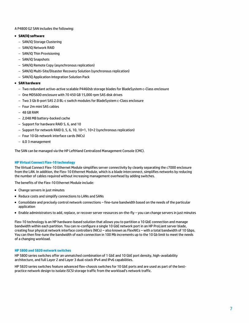
A P4800 G2 SAN includes the following:
SAN/iQ software
– SAN/iQ Storage Clustering
– SAN/iQ Network RAID
– SAN/iQ Thin Provisioning
– SAN/iQ Snapshots
– SAN/iQ Remote Copy (asynchronous replication)
– SAN/iQ Multi-Site/Disaster Recovery Solution (synchronous replication)
– SAN/iQ Application Integration Solution Pack
SAN hardware
– Two redundant active-active scalable P4460sb storage blades for BladeSystem c-Class enclosure
– One MDS600 enclosure with 70 450 GB 15,000 rpm SAS disk drives
– Two 3 Gb 8-port SAS 2.0 BL-c switch modules for BladeSystem c-Class enclosure
– Four 2m mini SAS cables
– 48 GB RAM
– 2,048 MB battery-backed cache
– Support for hardware RAID 5, 6, and 10
– Support for network RAID 0, 5, 6, 10, 10+1, 10+2 (synchronous replication)
– Four 10 Gb network interface cards (NICs)
– iLO 3 management
The SAN can be managed via the HP LeftHand Centralized Management Console (CMC).
HP Virtual Connect Flex-10 technology
The Virtual Connect Flex-10 Ethernet Module simplifies server connectivity by cleanly separating the c7000 enclosure from the LAN. In addition, the Flex-10 Ethernet Module, which is a blade interconnect, simplifies networks by reducing the number of cables required without increasing management overhead by adding switches.
The benefits of the Flex-10 Ethernet Module include:
Change servers in just minutes
Reduce costs and simplify connections to LANs and SANs
Consolidate and precisely control network connections – fine-tune bandwidth based on the needs of the particular application
Enable administrators to add, replace, or recover server resources on-the-fly – you can change servers in just minutes
Flex-10 technology is an HP hardware-based solution that allows you to partition a 10 GbE connection and manage bandwidth within each partition. You can re-configure a single 10 GbE network port in an HP ProLiant server blade, creating four physical network interface controllers (NICs) – also known as FlexNICs – with a total bandwidth of 10 Gbps. You can then fine-tune the bandwidth of each connection in 100 Mb increments up to the 10 Gb limit to meet the needs of a changing workload.
HP 5800 and 5820 network switches
HP 5800 series switches offer an unmatched combination of 1 GbE and 10 GbE port density, high-availability architecture, and full Layer 2 and Layer 3 dual-stack IPv4 and IPv6 capabilities.
HP 5820 series switches feature advanced flex-chassis switches for 10 GbE ports and are used as part of the best-practice network design to isolate iSCSI storage traffic from the workload’s network traffic.
8
VirtualSystem software
VirtualSystem VS2 includes the following software components:
Windows Server 2008 R2 SP1 with Hyper-V enabled
System Center Virtual Machine Manager 2008 R2 SP1 (SCVMM)
System Center Operations Manager 2007 R2 (SCOM)
HP Insight Control for Microsoft System Center
HP Storage Management Pack for Microsoft System Center
HP Service Pack for ProLiant (SPP)
HP LeftHand Central Management Console (CMC) – SAN/iQ 9.5
More information on these software components follows.
Windows Server 2008 R2 Hyper-V
Beginning with Windows Server 2008, server virtualization via Hyper-V technology has been an integral part of the operating system. Windows Server 2008 R2 introduced a new version of Hyper-V, making it easier to take advantage of the cost savings delivered by virtualization.
Windows Server 2008 R2 SP1 added dynamic memory capability to Hyper-V, enabling the density of VMs on a physical host to increase. The benefits of this version of Hyper-V include:
Higher availability for virtualized data centers through enhancements such as Live Migration
Improved management of virtualized data centers through integration with Windows PowerShell and System Center
Enhanced VM performance via processor compatibility mode
Enhanced scalability via support for 64 logical processors
Improved virtual networking performance
Simpler physical and virtual deployments using .vhd (virtual hard disk) files
System Center Virtual Machine Manager 2008 R2 SCVMM enables the centralized management of physical and virtual IT infrastructures, while increasing server utilization and dynamic resource optimization across multiple virtualization platforms.
SCVMM provides end-to-end capabilities including planning, deploying, managing, and optimizing the virtual infrastructure. Its benefits include:
Central creation and management of VMs across the entire data center
Easy consolidation of multiple physical servers on to virtualization hosts
Rapid provisioning and optimization of new and existing VMs
System Center Operations Manager 2007 R2 SCOM delivers capabilities in the following core areas:
End-to-end data center service management
Best-of-breed monitoring for Windows and beyond
Increased efficiency and control
SCOM helps you reduce the cost of data center management across server operating systems and hypervisors via a single, familiar, easy-to-use interface. You can obtain numerous views showing state, health and performance information, as well as alerts generated based on availability, performance, configuration, or security criteria. Thus, you can gain rapid insight into the state of the IT environment, as well as IT services running across different systems and workloads.
You can also improve availability and performance through enhanced service-level agreement (SLA) monitoring, while your operations staff gains better access to key functionality they need to maintain and enhance services delivered to end users.
9
For more information on System Center, visit http://www.microsoft.com/en-us/server-cloud/system-center/default.aspx.
SCOM management packs SCOM management packs provide the technology needed by the SCOM infrastructure to collect data from a monitored host, make intelligent decisions based on the data collected, and take appropriate action based on those decisions.
Microsoft and third parties create management packs for specific operating systems, applications, and network-connected hardware. The scenarios described in this white paper utilize the following SCOM management packs from Microsoft:
Windows Server Internet Information Services Library*
Windows Server Internet Information Services 2003*
Windows Server 2008 Internet Information Services 7*
Windows Server Operating System Library*
Windows Server 2008 Operating System (Discovery)*
Windows Server 2008 Operating System (Monitoring)
Windows Cluster Management Library
Windows Cluster Management Monitoring
Windows Server 2008 Cluster Management Library
Windows Server 2008 Cluster Management Monitoring SQL Server Core Library*
SQL Server 2008 (Discovery)
SQL Server 2008 (Monitoring)
* Required for Performance and Resource Optimization (PRO) integration with SCOM and SCVMM
VirtualSystem VS2 includes a five-day Start Service, delivered by HP Services professionals to help build the software environment. This service includes the deployment of SCVMM and SCOM; additional components can be deployed at your request. As of April 2012, the Start Service includes deployment of SCVMM 2008 R2 and SCOM 2007 on VirtualSystem; additional components can be deployed at customer‘s request. As of summer 2012, the Start Service is planned to implement the VMM and OM components of System Center 2012.
HP Insight Control for Microsoft System Center
HP Insight Control for Microsoft System Center provides seamless integration between ProLiant and BladeSystem manageability features and System Center consoles.
Licensed as part of HP Insight Control, HP Insight Control for Microsoft System Center provides comprehensive system health monitoring and alerting, configuration management, remote control, and proactive VM management in a flexible, easy-to-install package. Backed by HP service and support, HP Insight Control for Microsoft System Center delivers an outstanding hardware management experience for customers that have standardized on a System Center management platform.
The scenarios described in this white paper use ProLiant and BladeSystem management packs that are integrated with OM to expose the native capabilities of the HP hardware. OM Diagram, System, State, and Alert views provide enhanced visibility, enabling quick root cause analysis through graphical characterizations down to the server and blade subsystem level and, for c-Class enclosures, to the component level.
HP Storage Management Pack for Microsoft System Center
HP Storage Management Pack enables administrators to monitor Windows environments and HP storage products through a common OM console. The HP Storage Management Pack for Microsoft System Center includes the following features:
Support for events and alerts generated by P4800 SAN storage
Diagrammatic view of P4800 SANs
10
HP Service Pack for ProLiant (SPP)
SPP combines with HP Smart Update Manager to provide breakthrough system maintenance capabilities that can be used to systematically update servers and blade infrastructures with one-click simplicity, at the scale of your data center.
Important For any given Windows server, certain SPP components (such as HP Network Configuration Utility) must be installed after the Hyper-V role has been enabled. Thus, you should (1) deploy the Windows operating system, (2) enable the Hyper-V role, (3) reboot, and (4) install the complete SPP.
HP P4000 Central Management Console (CMC)
CMC is the management console for the P4000 SAN array family. CMC is a GUI Windows application and can be installed on any Windows server or Windows client machine and is the main central point for managing P4000 SAN.

11
Building a private cloud with SC2012 VMM
This section describes how HP used SC2012 VMM to build a private cloud with the HP VirtualSystem VS2 hardware environment, and provides information on the following topics:
Software versions used
Prerequisites
Instructions for the following activities:
– Creating logical networks
– Deploying Hyper-V hosts
– Configuring networks on Hyper-V hosts
– Configuring storage for Hyper-V hosts
– Building a Hyper-V cluster
– Deploying VMs
Software versions used
Table 1 shows the software versions used in the private cloud solution described in this document.
Table 1. Software versions used
Component Product and version
OS / hypervisor Windows Server 2008 R2 SP1 / Hyper-V
HP management HP Insight Control for Microsoft System Center 7.1 (beta release)
Virtual Connect Virtual Connect Manager 3.30
Onboard Administrator (OA) OA 3.31
P4800 G2 SAN CMC 9.5
ProLiant servers SPP 2012.01.0
Database Microsoft SQL Server 2008 SP2 or R2
VM management System Center 2012 Virtual Machine Manager release candidate (RC)
Operations management System Center 2012 Operations Manager RC
Workflows SC 2012 Orchestrator RC
Prerequisites
The procedures described in this document assume that default VirtualSystem VS2 hardware and software components have been pre-configured. In particular, the following assumptions are made:
The hardware has been racked and cabled.
The c7000 enclosure is fully configured; IP addresses for iLO have been populated.
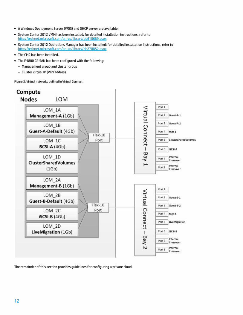
Virtual networks have been created and configured in Virtual Connect according to Figure 2 below.
A Windows Active Directory (AD) domain is available. In this scenario, the AD domain used is host.local.
12
A Windows Deployment Server (WDS) and DHCP server are available.
System Center 2012 VMM has been installed; for detailed installation instructions, refer to http://technet.microsoft.com/en-us/library/gg610669.aspx.
System Center 2012 Operations Manager has been installed; for detailed installation instructions, refer to http://technet.microsoft.com/en-us/library/hh278852.aspx.
The CMC has been installed.
The P4800 G2 SAN has been configured with the following:
– Management group and cluster group
– Cluster virtual IP (VIP) address
Figure 2. Virtual networks defined in Virtual Connect
The remainder of this section provides guidelines for configuring a private cloud.
13
Creating logical networks
VMM enables administrators to efficiently provision network resources for a virtualized environment with logical networks and network sites. You can build a network model in VMM that represents the underlying physical infrastructure in one or more data centers; VMM can then deploy Hyper-V hosts and VMs to specified networks.
In VMM, a logical network represents the abstraction layer for the physical network infrastructure and, with its associated network sites, consists of a user-defined collection of IP subnets and VLANs. You can assign logical networks as part of the VM creation process without needing to know the inner workings of these networks.
Configuring network global settings
When a host first boots, DNS settings have not yet been configured for host adapters; as a result, the name mapping of logical networks with DNS suffixes does not work. Fortunately, you can change the default mapping behavior by using the network connection name.
Use the following procedure to change the global network settings:
1. In the VMM console, open the Settings workspace.
2. In the Settings pane, click General.
3. In the right pane, click Network Settings.
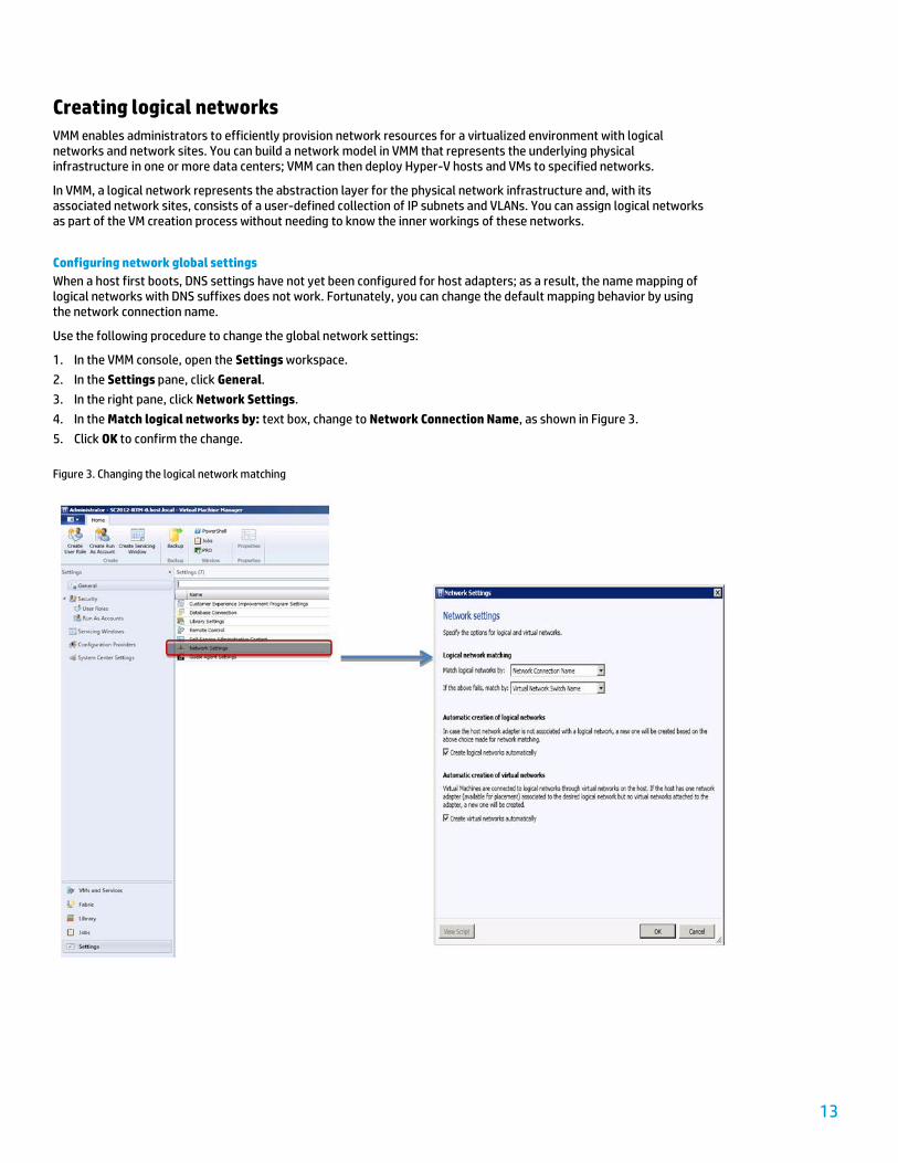
4. In the Match logical networks by: text box, change to Network Connection Name, as shown in Figure 3.
5. Click OK to confirm the change.
Figure 3. Changing the logical network matching
14
Creating logical networks and network sites
Every compute node in a VirtualSystem VS2 solution runs Windows Server 2008 R2 with Hyper-V enabled and has multiple network connections, as shown in Table 2.
Table 2. Network connections on compute nodes
Network connection Description
Guest-Team VM communications
Management-Team Management network
ClusterSharedVolume CSV network for Hyper-V cluster
LiveMigration LiveMigration network for Hyper-V cluster
iSCSI-A iSCSI network for P4800 G2 SAN storage
iSCSI-B iSCSI network for P4800 G2 SAN storage (redundant path)
For more information on the solution’s network configuration, refer to Configuring networks on Hyper-V hosts.
To represent the network topology in VMM, you must create logical networks with the same names as the network connections for compute nodes and configure network sites with the IP subnets defined in Table 3.
Table 3. Logical networks and network sites
Logical network Network site
Guest-Team Guest-Team-Site
Scope: All Hosts
Associated subnet: <subnet of Guest network>
Associated VLAN: None
Management-Team Management-Team-Site Scope: All Hosts
Associated subnet: <subnet of Mgt network>
Associated VLAN: None
ClusterSharedVolume ClusterSharedVolume-Site
Scope: All Hosts
Associated subnet: <subnet of CSV network>
Associated VLAN: None
LiveMigration LiveMigration-Site
Scope: All Hosts
Associated subnet: <subnet of LM network>
Associated VLAN: None
iSCSI-A iSCSI-A-Site
Scope: All Hosts
Associated subnet: <subnet of iSCSI-A network>
Associated VLAN: None
iSCSI-B iSCSI-B-Site
Scope: All Hosts
Associated subnet: <subnet of iSCSI-B network>
Associated VLAN: None
15
Use the following procedure to create logical networks from the VMM console:
1. In the console, open the Fabric workspace.
2. In the Fabric pane, click Networking.
3. From the menu bar, click Create Logical Network to open the Create Logical Network Wizard.
4. In the Name page, enter a name for a new logical network as specified in Table 3.
5. In the Network Site page, click Add.
6. Click All Hosts.
7. Click Insert row. Enter the IP subnet as defined in Table 3.
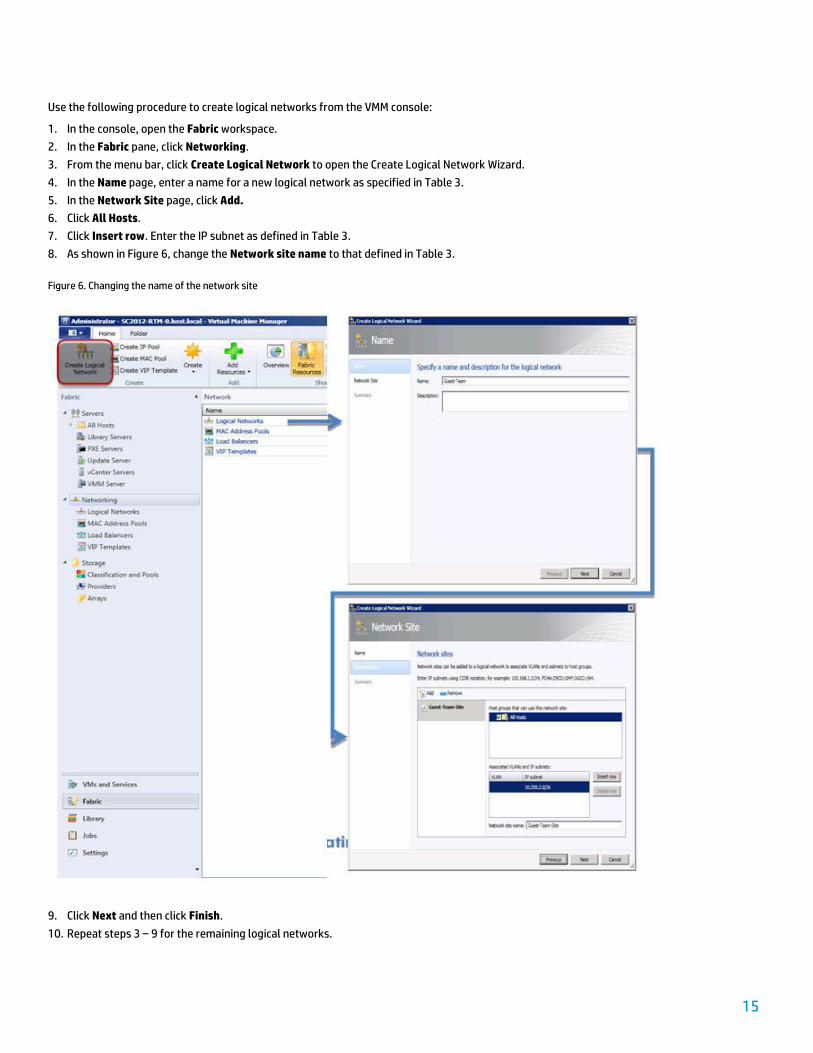
8. As shown in Figure 6, change the Network site name to that defined in Table 3.
Figure 6. Changing the name of the network site
9. Click Next and then click Finish.
10. Repeat steps 3 – 9 for the remaining logical networks.
16
Deploying Hyper-V hosts
VMM supports the installation of the Windows OS and Hyper-V on physical hosts. This capability leverages the existing Windows server infrastructure including DHCP and WDS for physical server deployment. VMM can also use the boot from virtual hard drive (VHD) feature in Windows Server 2008 to deploy an OS VHD to the local disk of the physical server rather than installing binaries on the physical disk.
Preparing the boot.wim file
The boot.wim file contains the custom WinPE image to communicate with the VMM console and used by the WDS server to trigger the host deployment process. In general, the boot.wim file includes all the network drivers from the Windows Server 2008 R2 Hardware Compatibility list and can thus enable WinPE to communicate with various servers during its bootstrap. However, the file does not include drivers for hardware released after Windows Server 2008 R2 Release To Manufacturers (RTM). As a result, you may need to add new network drivers to the WinPE environment to enable connectivity when the system boots.
The BL460c G7 server blades featured in VirtualSystem VS2 were released after Windows Server 2008 R2 was made available; as a result, you need to add the appropriate network driver. This blade has two Flex-10 ports on its motherboard and uses a network driver – HP NC-Series Emulex 10GbE Driver for Windows Server 2008 R2 – that is based on the Emulex 10 GbE driver. The latest release of the network driver can be downloaded from the Download drivers and software page; see the Driver-Network list.
To install the network driver on WinPE, you need to mount the boot.wim file to a temporary folder and add the driver by using the Windows Deployment Image Servicing and Management (DISM) utility. Use the following procedure:
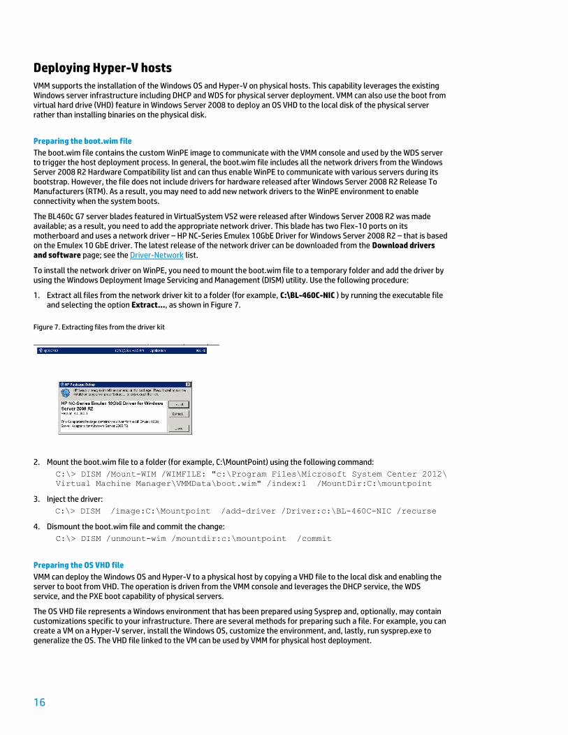
1. Extract all files from the network driver kit to a folder (for example, C:\BL-460C-NIC ) by running the executable file and selecting the option Extract…, as shown in Figure 7.
Figure 7. Extracting files from the driver kit
2. Mount the boot.wim file to a folder (for example, C:\MountPoint) using the following command:
C:\> DISM /Mount-WIM /WIMFILE: "c:\Program Files\Microsoft System Center 2012\
Virtual Machine Manager\VMMData\boot.wim" /index:1 /MountDir:C:\mountpoint
3. Inject the driver:
C:\> DISM /image:C:\Mountpoint /add-driver /Driver:c:\BL-460C-NIC /recurse
4. Dismount the boot.wim file and commit the change:
C:\> DISM /unmount-wim /mountdir:c:\mountpoint /commit
Preparing the OS VHD file
VMM can deploy the Windows OS and Hyper-V to a physical host by copying a VHD file to the local disk and enabling the server to boot from VHD. The operation is driven from the VMM console and leverages the DHCP service, the WDS service, and the PXE boot capability of physical servers.
The OS VHD file represents a Windows environment that has been prepared using Sysprep and, optionally, may contain customizations specific to your infrastructure. There are several methods for preparing such a file. For example, you can create a VM on a Hyper-V server, install the Windows OS, customize the environment, and, lastly, run sysprep.exe to generalize the OS. The VHD file linked to the VM can be used by VMM for physical host deployment.

17
Alternatively, you can use the WIM2VHD Converter tool to prepare the OS VHD file. WIM2VHD leverages the ImageX feature of the Windows Automated Installation Kit (WAIK) to expand the binaries from the .wim file to a VHD file. WIM2VHD generates a bootable VHD that represents a Windows environment that has been prepared with Sysprep.
Note The WIM2VHD Converter tool can be run from any Windows 7 or Windows Server 2008 R2 system with WAIK installed.
Use the following procedure to prepare the OS VHD file:
1. Open a command window with administrative privileges.
2. Run the following command to create a OS VHD file:
C:\>WIM2VHD.WSF /WIM:<DVD-Drive>:\Sources\install.wim /SKU:ServerDataCenter
/VHD:C:\WS08R2Sp1.VHD /DiskType:Dynamic
Note The default size is 40 GB.
3. Use Disk Management to mount the VHD file as a drive, as shown in Figure 8. Use V: as drive letter.
Figure 8. Mounting the VHD file as a Windows drive
4. Customize the environment by adding folders and files. In this scenario, the following folders are created:
– C:\Kits\SPP Contains the binaries of the Service Pack for ProLiant (SPP)
– C:\Scripts: Contains the RunOnce.cmd batch file to install SPP
– C:\VSConfig\Logs: Contains log files
5. In the same way as in the WinPE environment, you must add the network driver for the Flex-10 ports on the BL460c G7 server blade’s motherboard. Use the following command:
C:\>DISM /image:V:\ /add-driver /Driver:c:\BL-460-NIC /recurse
18
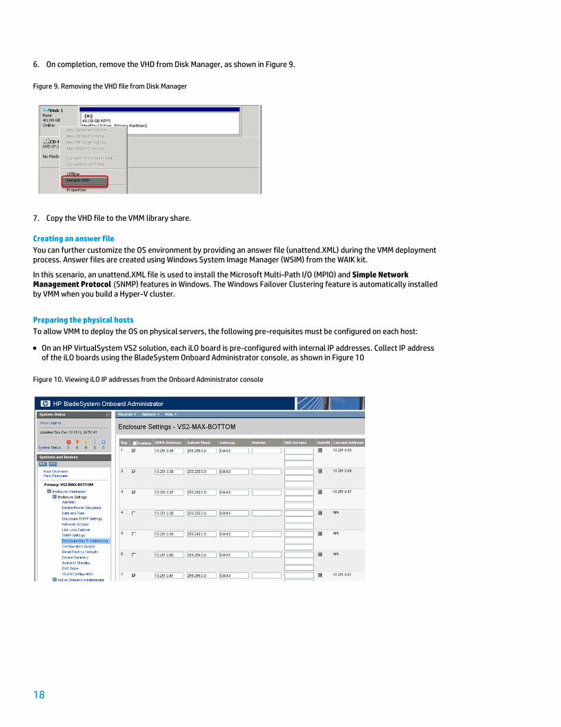
6. On completion, remove the VHD from Disk Manager, as shown in Figure 9.
Figure 9. Removing the VHD file from Disk Manager
7. Copy the VHD file to the VMM library share.
Creating an answer file
You can further customize the OS environment by providing an answer file (unattend.XML) during the VMM deployment process. Answer files are created using Windows System Image Manager (WSIM) from the WAIK kit.
In this scenario, an unattend.XML file is used to install the Microsoft Multi-Path I/O (MPIO) and Simple Network Management Protocol (SNMP) features in Windows. The Windows Failover Clustering feature is automatically installed by VMM when you build a Hyper-V cluster.
Preparing the physical hosts
To allow VMM to deploy the OS on physical servers, the following pre-requisites must be configured on each host:
On an HP VirtualSystem VS2 solution, each iLO board is pre-configured with internal IP addresses. Collect IP address of the iLO boards using the BladeSystem Onboard Administrator console, as shown in Figure 10
Figure 10. Viewing iLO IP addresses from the Onboard Administrator console
19
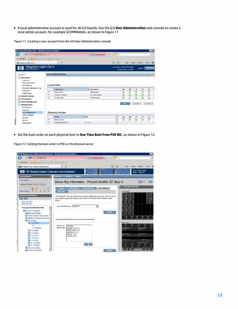
A local administrative account is used for all iLO boards. Use the iLO User Administration web console to create a local admin account, for example SCVMMAdmin, as shown in Figure 11
Figure 11. Creating a user account from the iLO User Administration console
Set the boot order on each physical host to One Time Boot from PXE NIC, as shown in Figure 12.
Figure 12. Setting the boot order to PXE on the physical server

20
Configuring a PXE server
You can deploy the WDS role on a Windows Server 2008 R2 system to act as a PXE server. When installing WDS, ensure you select the Deployment Server and Transport Server options; in addition, note that the WDS server must be on the same subnet as the physical hosts.
Configuring VMM for the deployment of physical hosts
Deploying Hyper-V on physical hosts is a task that can now be performed from the VMM console. You no longer need to navigate through different interfaces and use different tools to install the OS on servers, enable Hyper-V, and, later, add the Hyper-V server to VMM.
The host deployment wizard in the VMM console will guide you through the tasks required to deploy physical hosts, requesting very few input parameters. All complex tasks are carried out in the background by the VMM server.
To enable host deployment feature, you should complete the following prerequisites:
Create Run As accounts with domain administrator privileges and iLO credentials.
Add a PXE server to the VMM console.
Create a host profile with an OS VHD.
Use the following procedures to complete the prerequisites.
Creating Run As accounts 1. In the VMM console, open the Settings workspace.
2. In the Settings pane, click Security.
3. In the menu bar, click Create Run As Account.
21
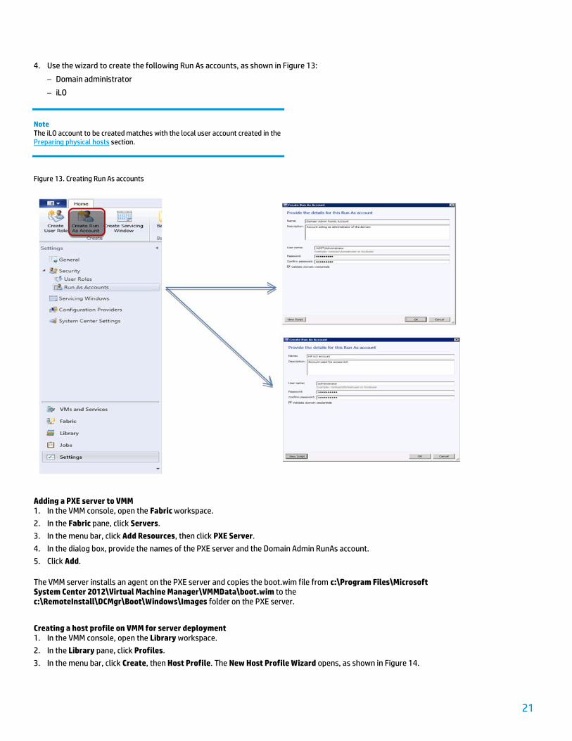
4. Use the wizard to create the following Run As accounts, as shown in Figure 13:
– Domain administrator
– iLO
Note The iLO account to be created matches with the local user account created in the Preparing physical hosts section.
Figure 13. Creating Run As accounts
Adding a PXE server to VMM 1. In the VMM console, open the Fabric workspace.
2. In the Fabric pane, click Servers.
3. In the menu bar, click Add Resources, then click PXE Server.
4. In the dialog box, provide the names of the PXE server and the Domain Admin RunAs account.
5. Click Add.
The VMM server installs an agent on the PXE server and copies the boot.wim file from c:\Program Files\Microsoft System Center 2012\Virtual Machine Manager\VMMData\boot.wim to the c:\RemoteInstall\DCMgr\Boot\Windows\Images folder on the PXE server.
Creating a host profile on VMM for server deployment 1. In the VMM console, open the Library workspace.
2. In the Library pane, click Profiles.
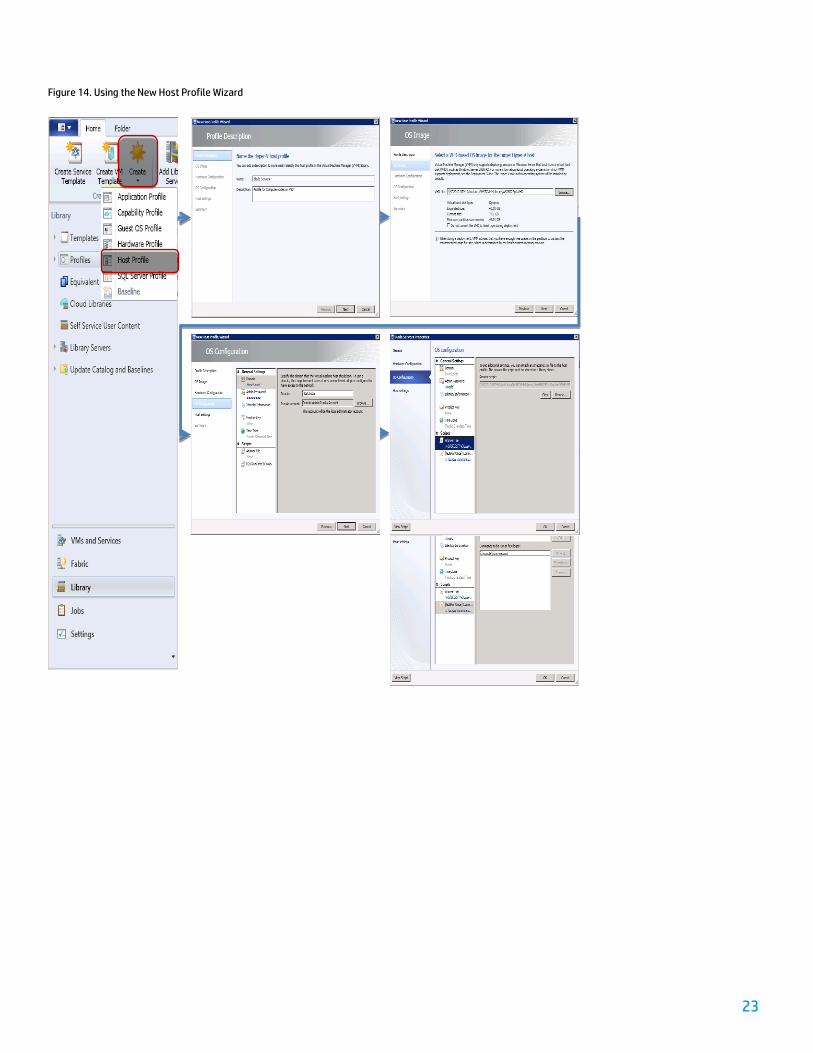
3. In the menu bar, click Create, then Host Profile. The New Host Profile Wizard opens, as shown in Figure 14.
22
4. In the Profile Description page, enter a name for the profile, for example Blade Servers. Click Next.
5. In the OS Image page, click Browse and select the VHD created in the Preparing the OS VHD file section from the VMM library. Click Next.
6. In the Hardware Configuration page, review the default options. Click Next.
7. Perform the following steps in the OS Configuration page:
a) Click Domain in the left pane and provide the name of the Windows domain the computer will join. Browse and select the Domain Admin RunAs account.
b) Click Admin Password in the left pane and provide a password for the local administrator account.
c) Click Answer File in the left pane. Click Browse and select the unattend.xml file stored in the library. Click Yes when prompted for confirmation.
d) Click [GUI RunOnce] Command in the left pane. Type in C:\Scripts\RunOnce.cmd and click Add.
Note The RunOnce.cmd is created in the Preparing the OS VHD file section.
e) Click Next.
8. In the Host Settings page, specify a path for storing VMs. Click Next when done.
9. In the Summary page, review the selected options and click Finish.
23
Figure 14. Using the New Host Profile Wizard

24
Deploying Hyper-V hosts
All the components are now in place to enable host deployment with VMM. Use the following procedure to initiate an OS deployment on physical servers.
1. In the VMM console, open the Fabric workspace.
2. In the Fabric pane, click Servers.
3. In the menu bar, click Add Resources, then click Hyper-V Hosts and Clusters, as shown in Figure 15.
4. In the Resource location page, click Physical computers to be provisioned as virtual machine hosts. Click Next.
5. In the Credentials and protocol page, click Browse and select the iLO admin Run As account previously created. Click OK. Review the default selection for Out-of-Band management protocol: IPMI on port 623. Click Next.
6. On the Discovery scope page, click IP range and provide a range of iLO IP addresses. Click Next.
7. In the Target resources page, click Select All, then click Next.
8. In the Provisioning options page, review the default selection and click Next.
9. In the Deployment customization page, provide the name of each computer to be deployed. Click Next.
10. In the Summary page, review the selection and click Finish.
VMM starts the jobs necessary to deploy Hyper-V on the physical hosts.
Figure 15. Deploying Hyper-V hosts
25
Configuring networks on Hyper-V hosts
After the operating system has been deployed and has joined the domain, you need to take additional steps to configure the networking environment. For example, you should update LAN network names to match pre-defined virtual networks in Virtual Connect and, for some networks, build a NIC teaming configuration to provide redundancy.
Virtual Connect networks
In VirtualSystem VS2, several virtual networks have already been defined in the Virtual Connect modules installed in the c7000 enclosure; further, profiles containing virtual network assignments are attached to each bay in the enclosure. As a result, when a blade server is inserted into any bay and powered on, it is given the network cards (FlexNICs) specified in the profile for that slot.
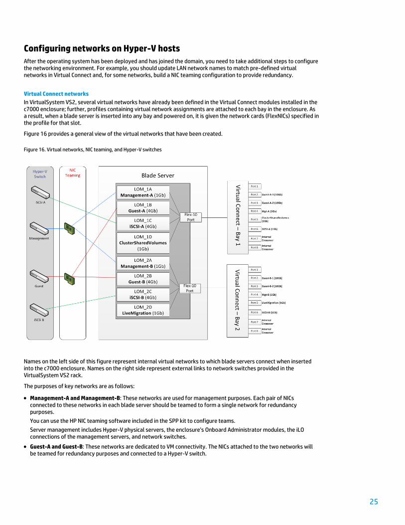
Figure 16 provides a general view of the virtual networks that have been created.
Figure 16. Virtual networks, NIC teaming, and Hyper-V switches
Names on the left side of this figure represent internal virtual networks to which blade servers connect when inserted into the c7000 enclosure. Names on the right side represent external links to network switches provided in the VirtualSystem VS2 rack.
The purposes of key networks are as follows:
Management-A and Management-B: These networks are used for management purposes. Each pair of NICs connected to these networks in each blade server should be teamed to form a single network for redundancy purposes.
You can use the HP NIC teaming software included in the SPP kit to configure teams.
Server management includes Hyper-V physical servers, the enclosure’s Onboard Administrator modules, the iLO connections of the management servers, and network switches.
Guest-A and Guest-B: These networks are dedicated to VM connectivity. The NICs attached to the two networks will be teamed for redundancy purposes and connected to a Hyper-V switch.
26
iSCSI-A and iSCSI-B: These networks are reserved for iSCSI communications between servers, VMs, and P4800 G2 SAN storage.
MPIO will be used to configure redundant paths for iSCSI traffic.
LiveMigration and ClusterSharedVolumes: These components make up a single network dedicated to Windows failover clustering for Hyper-V hosts.
Procedures for network configuration follow.
Renaming LAN networks
When a blade server boots into Windows, the names of network connections are set to Local Area Connection #, where # is the index number assigned to a connection by Windows when the NIC is discovered. As a result, it may be a challenge to correctly identify network connections when creating a NIC team. HP suggests renaming these networks to match the virtual networks created in Virtual Connect via the following approach:
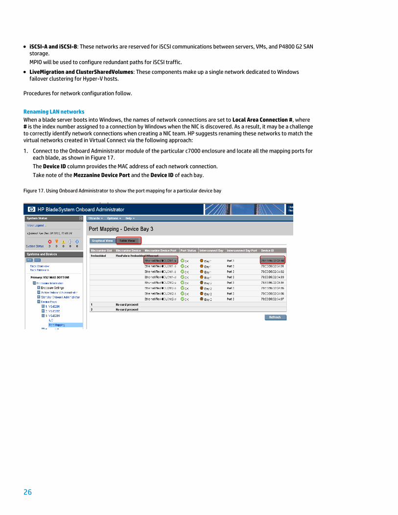
1. Connect to the Onboard Administrator module of the particular c7000 enclosure and locate all the mapping ports for each blade, as shown in Figure 17.
The Device ID column provides the MAC address of each network connection.
Take note of the Mezzanine Device Port and the Device ID of each bay.
Figure 17. Using Onboard Administrator to show the port mapping for a particular device bay
27
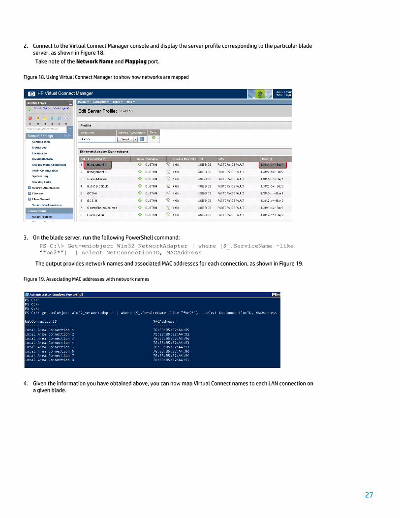
2. Connect to the Virtual Connect Manager console and display the server profile corresponding to the particular blade server, as shown in Figure 18.
Take note of the Network Name and Mapping port.
Figure 18. Using Virtual Connect Manager to show how networks are mapped
3. On the blade server, run the following PowerShell command:
PS C:\> Get-wmiobject Win32_NetworkAdapter | where {$_.ServiceName –like
“*be2*”} | select NetConnectionID, MACAddress
The output provides network names and associated MAC addresses for each connection, as shown in Figure 19.
Figure 19. Associating MAC addresses with network names
4. Given the information you have obtained above, you can now map Virtual Connect names to each LAN connection on a given blade.
28
Creating NIC teams
HP ProLiant Network Adapter Teaming is a software-based technology that allows you to team two or more NIC ports together so that they function as a single network adapter, thus providing fault tolerance and load balancing capabilities.
In this example, two NIC teams are created on the VirtualSystem VS2 solution, one for the Management network and one for the Guest network. The steps required to create the NIC teams are as follows and must be repeated on every compute node.
1. Using iLO remote console functionality, connect to the desktop of a compute node.
2. From the Start menu, open a command prompt using the Run as Administrator option.
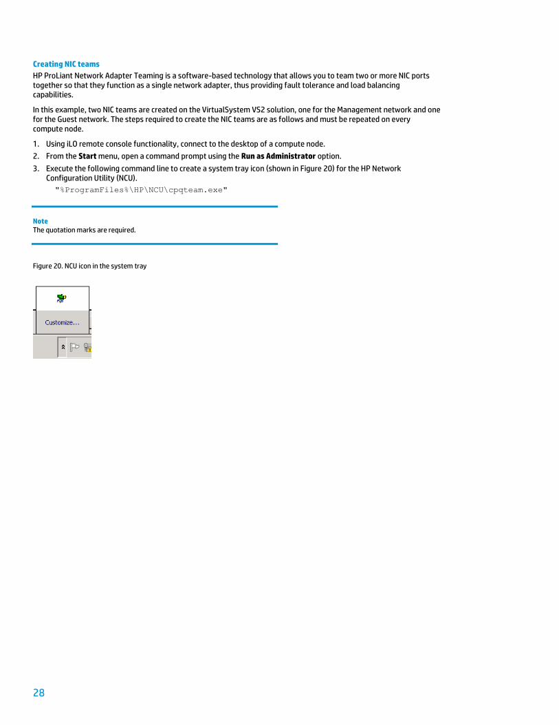
3. Execute the following command line to create a system tray icon (shown in Figure 20) for the HP Network Configuration Utility (NCU).
"%ProgramFiles%\HP\NCU\cpqteam.exe"
Note The quotation marks are required.
Figure 20. NCU icon in the system tray

29
4. Double-click the NCU system tray icon. The utility should open within a few seconds.
Select the specific ports that make up the Management team; that is, Management-A and Management-B, as shown in Figure 21.
Figure 21. Selecting the ports required for the Management team
5. Click the Team button.
6. Click the Properties button.
7. In Team Type Selection, select Transmit Load Balancing with Fault Tolerance (TLB).
8. Change the Team Name to Management-Team.
Important Correctly naming the NIC team will be critical later in the deployment process. You must perform the team type selection before you name the team.
9. Click OK to close the Properties page.
30
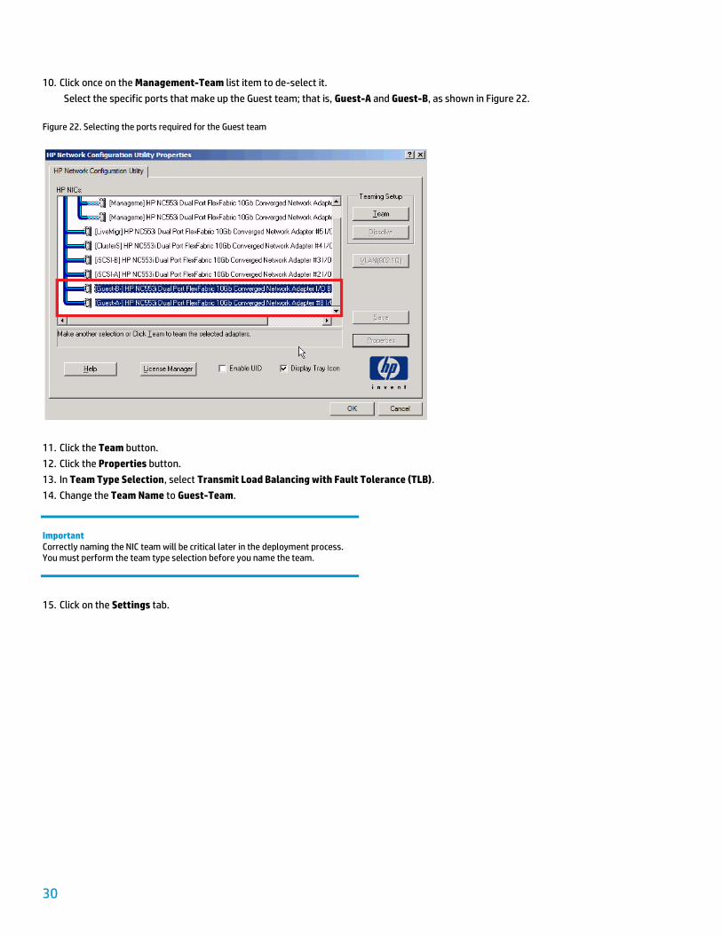
10. Click once on the Management-Team list item to de-select it.
Select the specific ports that make up the Guest team; that is, Guest-A and Guest-B, as shown in Figure 22.
Figure 22. Selecting the ports required for the Guest team
11. Click the Team button.
12. Click the Properties button.
13. In Team Type Selection, select Transmit Load Balancing with Fault Tolerance (TLB).
14. Change the Team Name to Guest-Team.
Important Correctly naming the NIC team will be critical later in the deployment process. You must perform the team type selection before you name the team.
15. Click on the Settings tab.
31
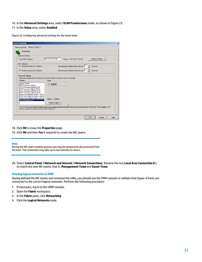
16. In the Advanced Settings area, select VLAN Promiscuous mode, as shown in Figure 23.
17. In the Value area, select Enabled.
Figure 23. Configuring advanced settings for the Guest team
18. Click OK to close the Properties page.
19. Click OK and then Yes if required to create the NIC teams.
Note During the NIC team creation process you may be temporarily disconnected from the host. The connection may take up to two minutes to return.
20. Select Control PanelNetwork and InternetNetwork Connections. Rename the two Local Area Connection #’s to match the new NIC teams; that is, Management-Team and Guest-Team.
Viewing logical networks in VMM
Having defined the NIC teams and renamed the LANs, you should use the VMM console to validate that Hyper-V hosts are connected to the correct logical networks. Perform the following procedure:
1. If necessary, log in to the VMM console.
2. Open the Fabric workspace.
3. In the Fabric pane, click Networking.
4. Click the Logical Networks node.

32
5. In the right pane, you should see a list of logical networks that map to the names of LANs on each compute node. If you do not see the full list as shown in Figure 24, go back to the Servers hierarchy, and expand All Hosts. For each server listed in the right pane, right-click on Refresh to ensure that VMM gets the latest configuration from each server.
6. Right-click each logical network name and select View Dependent Resources. Ensure that you receive a list of all servers for each logical network name.
Figure 24. Logical networks with dependencies
Note If you only see Local Area Connection # listed as the name for the logical networks – even after several host refreshes – try removing all servers from the VMM console and then re-adding them.
Configuring storage for Hyper-V hosts
When creating a Windows failover cluster in a VirtualSystem VS2 system, each Hyper-V host requires access to shared SAN storage.
VMs’ hard disks (VHD files) are hosted on LUNs that are exposed to all nodes in a cluster, allowing you to balance workloads through live migration between nodes.
At a minimum, the following two shared LUNs must exist in a Hyper-V cluster:
Witness disk (1 GB minimum)
Disk volume to host VHDs
In an iSCSI SAN, storage configuration is a two-stage process:
1. Using the storage management console to create RAW LUNs , register host initiator names, and present LUNs to hosts
2. Using the iSCSI initiator interface to create connections between each Hyper-V host and the targeted LUNs, and then running MPClaim to enable multipathing with MPIO.
Use the following procedures to configure storage for Hyper-V hosts.
33
Creating LUNs
Use the following procedure to create LUNs on the P4800 G2 SAN:
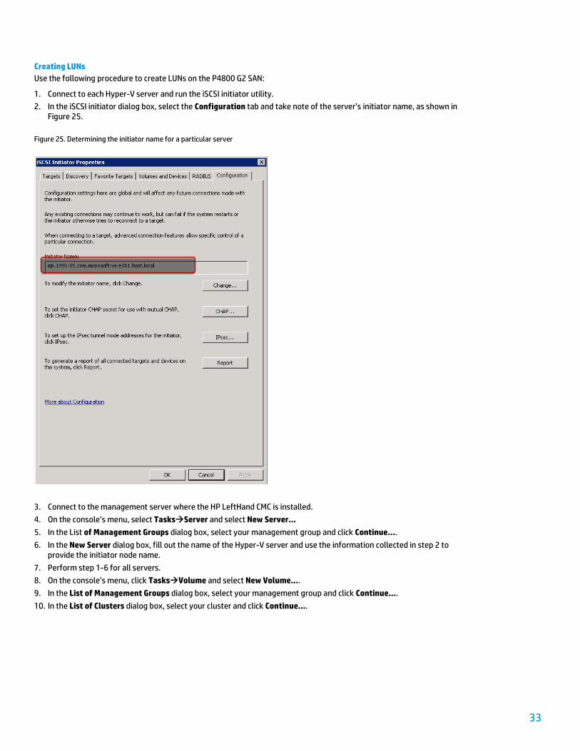
1. Connect to each Hyper-V server and run the iSCSI initiator utility.
2. In the iSCSI initiator dialog box, select the Configuration tab and take note of the server’s initiator name, as shown in Figure 25.
Figure 25. Determining the initiator name for a particular server
3. Connect to the management server where the HP LeftHand CMC is installed.
4. On the console’s menu, select TasksServer and select New Server…
5. In the List of Management Groups dialog box, select your management group and click Continue….
6. In the New Server dialog box, fill out the name of the Hyper-V server and use the information collected in step 2 to provide the initiator node name.
7. Perform step 1-6 for all servers.
8. On the console’s menu, click TasksVolume and select New Volume….
9. In the List of Management Groups dialog box, select your management group and click Continue….
10. In the List of Clusters dialog box, select your cluster and click Continue….
34
11. In the New Volume dialog box, enter a volume name and specify its size based on the following recommendations:
Disk Name Recommended size
Witness WitnessDisk 1 GB
Cluster Shared Volume CSV-1 Minimum 5 GB
12. Click Assign and Unassign Servers.
13. In the dialog box, check the Assigned box for each server. Click OK then Continue to confirm the changes.
14. Click OK to close the New Volume dialog box.
15. Perform steps 8-14 for the remaining LUNs.
Connecting LUNs to Hyper-V hosts
After the LUNs have been created and presented to hosts, use the iSCSI initiator on each Hyper-V host to create permanent iSCSI connections to those LUNs. Perform the following procedure:
1. If necessary, login to each Hyper-V host.
2. Open the iSCSI initiator tool.
3. In the iSCSI Initiator Properties dialog box, click the Discovery tab and then the Discovery Portal… button.
4. In the Discovery Target Portal dialog box, enter either the DNS name of the SAN storage or its virtual IP address. Use the default port number value (2360) and then click OK.
5. Click the Targets tab. You should see the two target LUNs created earlier. Select each item and click Connect. Ensure that the Add this connection to the list of Favorite Targets and Enable multi-path are selected then click OK to confirm the changes.
6. Once all the targets are connected, click OK to close the iSCSI initiator tool.
7. Open the Server Manager tool and go to the Storage hierarchy. Right click Disk Management and select Rescan Disks. You should see two new disks in an offline state.
Note If you see multiple instances of the same volume, run the MPIO utility. In the Properties dialog box, click the Discover Multi Paths tab and then click Add. MPIO will discover the devices and enable multi paths. Reboot the system after this operation completes.
Building a Hyper-V cluster
Before building a Hyper-V cluster, it may be beneficial to review the tasks that you have just completed, which are:
1. Configure logical networks in VMM
2. Deploy the OS and enable Hyper-V on physical hosts
3. Configure physical NICs on Hyper-V hosts (renaming LANs, creating NIC teams)
4. Provision storage
You are now ready to create a Hyper-V cluster.
Traditionally, administrators use the Windows Failover Cluster management tool to build a cluster. However, before the cluster creation can begin, the following manual steps must be completed:
1. Install Windows Failover Cluster features on each physical host
2. Provision storage and present it to each host using SAN management tools
3. On one physical host, bring the new disks online and format them
35
With SC2012 VMM, administrators can create Hyper-V clusters directly from the VMM console without the need to use multiple tools to prepare hosts and storage for cluster creation.
The manual steps described above are now performed by VMM on behalf of the administrator:
1. VMM agents running on the Hyper-V hosts will ensure that the Windows Failover Cluster feature is installed in the OS. If necessary, VMM agents can trigger installation of this feature.
2. VMM supports Storage Management Initiative – Specification (SMI-S) as the standard protocol for storage management. If your storage supports SMI-S and is certified for SC2012 VMM, you can provision storage LUNs directly from the VMM console. Otherwise, you can still provision LUNs outside of VMM using the vendor’s storage management interface.
After creating the LUNs, you should assign them to the host groups for the Hyper-V servers you wish to cluster. The VMM cluster creation process uses this information on host groups to automatically present LUNs to each individual host in the group.
3. When creating the cluster, VMM uses one physical host to bring all disks online and format them automatically via the agent running on that host.
Use the following procedure to build a Hyper-V cluster from SC 2012 VMM:
1. If necessary, log in to the VMM console.
2. Open the Fabric workspace.
3. Click the Servers hierarchy.
4. In the menu bar, click Create and then click Hyper-V Cluster to open the Create Cluster Wizard.
5. On the General page, enter a name for the cluster, for example VS-Cluster.
6. Click Browse…, select Domain Admin RunAs Account, and click OK. Click Next.
On the Nodes page, select all Hyper-V servers to be clustered, click Add>. Click Next.
Note You can skip the cluster validation tests by checking the Skip cluster validation tests box.
7. On the Storage page, specify a name for the LUN to be used as the CSV. Check the Quick Format and CSV boxes. Click Next.
8. On the Virtual Networks page, select the networks where you want to create a Hyper-V switch. In this scenario, Guest-Team, iSCSI-A, iSCSI-B, Management-Team are selected. Provide details on how you want to configure the Hyper-V switch, specifically:
– Name the Hyper-V switch
– Specify how a physical host connects to the switch
– Optionally, provide a VLAN ID for the physical host
Click Next.
9. On the Summary page, review your selections and click Finish to start the operation.
After the operation is completed, you can view the state of the cluster directly from the VMM console or use the cluster manager in the Hyper-V host.
36
Deploying virtual machines
The infrastructure is now ready to begin hosting workloads.
VirtualSystem VS2 allows you to create VMs to run your business applications. With shared storage, these VMs can be highly available, leveraging the Hyper-V Live Migration feature to move workloads from one host to another without disruption.
Note Although it is not highly recommended, VMs may be deployed on the local storage of a Hyper-V host.
SC2012 VMM allows you to deploy workload services representing single- or multi-tier applications rather than independent VMs. Using a service template, you can quickly design, deploy and manage a group of VMs as a cohesive service.
Consult the following guides for more information:
Deploying VMs: http://technet.microsoft.com/en-us/library/gg610679.aspx
Deploying services: http://technet.microsoft.com/en-us/library/gg675074.aspx
Monitoring a private cloud with SC2012 Operations Manager
SC2012 OM provides an end-to-end data center service management and monitoring framework. Administrators can use a single console to monitor the applications, system services, and operating systems running on many servers. In addition, operators can obtain numerous views showing state, health, and performance information, as well as alerts generated according to availability, performance, configuration, or security criteria.
In VirtualSystem VS2, the addition of HP Insight Control for System Center and HP Storage Management Pack for System Center bring native management capabilities of HP hardware into OM. As a result, you can gain rapid insight into the state of the IT environment from the hardware to Hyper-V, to workloads running on top of the hypervisor, and finally to the applications inside those workloads.
The following are mandatory tasks that must be performed so that you can monitor the private cloud:
Note It is assumed that an SC2012 OM server is available. For more information, refer to http://technet.microsoft.com/en-us/library/hh278852.aspx.
Add Hyper-V hosts to the Operations console
Create a connection between VMM and OM.
Install HP Insight Control for Microsoft System Center (IC-SC)
Install HP Storage Management Pack for Microsoft SC2012 OM
Instructions for each of these tasks follow.
37
Adding Hyper-V hosts to the Operations console
Use the following procedure to add Hyper-V hosts to the Operations console:
1. Log in to the Operations console.
2. In the right pane, click Required: Configure computers and devices to manage.
3. Click Windows Computers and then click Next.
4. Ensure that the Advanced discovery option is selected and then click Next.
5. Click Browse for, or type-in computer names.
6. Type in the name of the Hyper-V hosts, then click Next.
7. Click Other user Account.
8. Provide the Domain Administrator credential and then click Discover.
9. Click Select All and then click Next.
10. Click Finish.
11. When the deployment job has finished, click Close.
12. Click the Agent Managed node.
13. In the Agent Managed pane, right-click the host to which you have deployed an OM agent and select Properties.
14. Click the Security page and enable Allow this agent to act as a proxy and discover managed objects on other computers, then click OK.
Enabling this option allows the OM agent to manage other objects that are subordinate to the managed host, such as VMs and the Windows cluster
Configuring OM connections to VMM
Use the following procedure to configure OM connections to VMM:
1. Log into the VMM server.
2. Install the OM management console.
3. Connect to the VMM console.
4. In the Settings tab, click System Center Settings.
5. Right click Operations Manager Server and select Properties.
6. Follow the wizard to add the OM server.
38
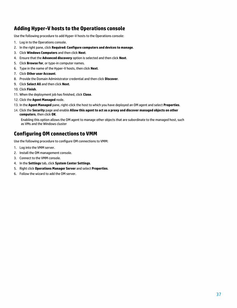
7. Wait for the job to complete. Open the Properties window again and ensure that connection status is OK, as shown in Figure 26.
Figure 26. Verifying that connection status is OK
Installing IC-SC
IC-SC provides management packs for monitoring BladeSystem enclosures, as well as ProLiant BL- and DL-series servers.
Note IC-SC is part of HP Insight Control Suite 7.
Use the following procedure to install and configure IC-SC:
1. Follow the instructions detailed in the HP Insight Control for Microsoft System Center Installation and Configuration Guide to install IC-SC. Install the following features:
– HP Device Monitor Console
– Management packs
39
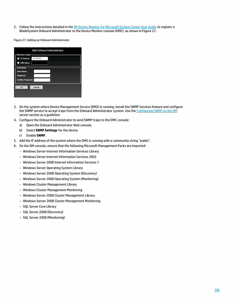
2. Follow the instructions detailed in the HP Device Monitor for Microsoft System Center User Guide to register a BladeSystem Onboard Administrator to the Device Monitor console (DMC), as shown in Figure 27.
Figure 27. Adding an Onboard Administrator
3. On the system where Device Management Service (DMS) is running, install the SNMP Services feature and configure the SNMP service to accept traps from the Onboard Administrator system. Use the Configuring SNMP on the OM server section as a guideline.
4. Configure the Onboard Administrator to send SNMP traps to the DMC console:
a) Open the Onboard Administrator Web console.
b) Select SNMP Settings for the device.
c) Enable SNMP.
5. Add the IP address of the system where the DMS is running with a community string “public”.
6. On the OM console, ensure that the following Microsoft Management Packs are imported:
– Windows Server Internet Information Services Library
– Windows Server Internet Information Services 2003
– Windows Server 2008 Internet Information Services 7
– Windows Server Operating System Library
– Windows Server 2008 Operating System (Discovery)
– Windows Server 2008 Operating System (Monitoring)
– Windows Cluster Management Library
– Windows Cluster Management Monitoring
– Windows Server 2008 Cluster Management Library
– Windows Server 2008 Cluster Management Monitoring
– SQL Server Core Library
– SQL Server 2008 (Discovery)
– SQL Server 2008 (Monitoring)
40
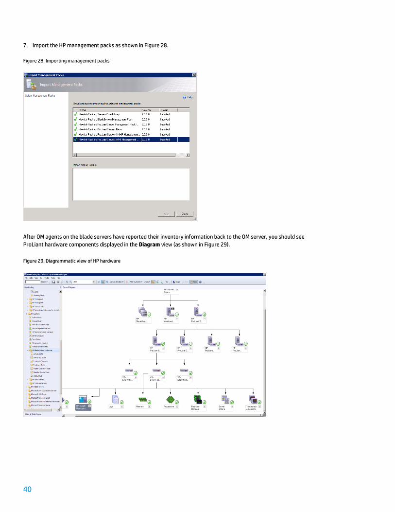
7. Import the HP management packs as shown in Figure 28.
Figure 28. Importing management packs
After OM agents on the blade servers have reported their inventory information back to the OM server, you should see
ProLiant hardware components displayed in the Diagram view (as shown in Figure 29).
Figure 29. Diagrammatic view of HP hardware
41
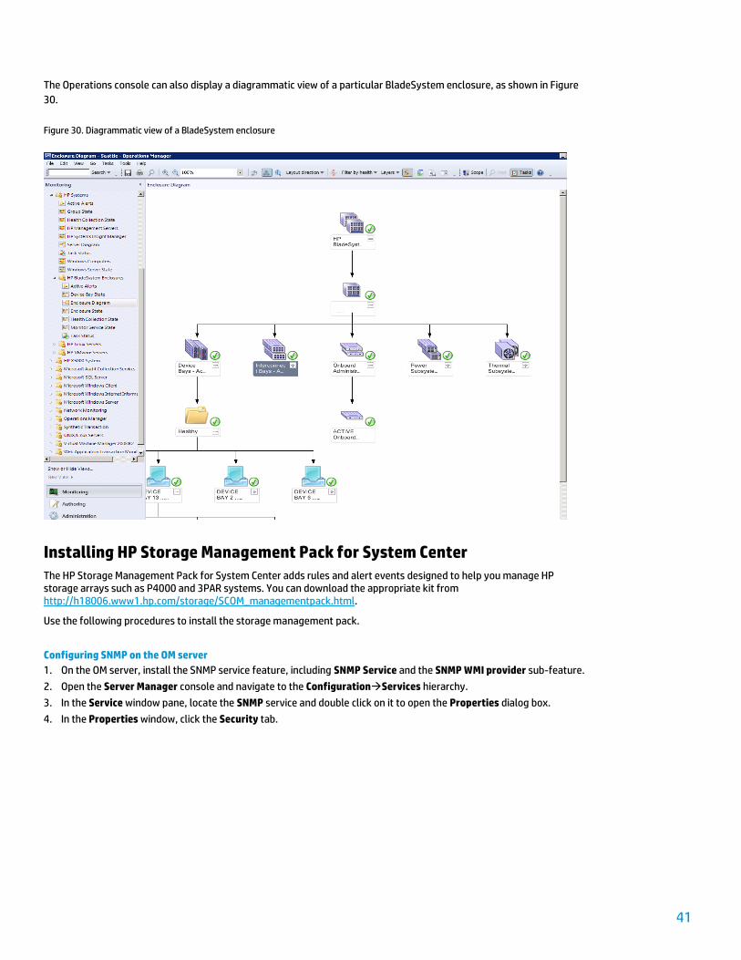
The Operations console can also display a diagrammatic view of a particular BladeSystem enclosure, as shown in Figure
30.
Figure 30. Diagrammatic view of a BladeSystem enclosure
Installing HP Storage Management Pack for System Center
The HP Storage Management Pack for System Center adds rules and alert events designed to help you manage HP storage arrays such as P4000 and 3PAR systems. You can download the appropriate kit from http://h18006.www1.hp.com/storage/SCOM_managementpack.html.
Use the following procedures to install the storage management pack.
Configuring SNMP on the OM server
1. On the OM server, install the SNMP service feature, including SNMP Service and the SNMP WMI provider sub-feature.
2. Open the Server Manager console and navigate to the ConfigurationServices hierarchy.
3. In the Service window pane, locate the SNMP service and double click on it to open the Properties dialog box.
4. In the Properties window, click the Security tab.
42
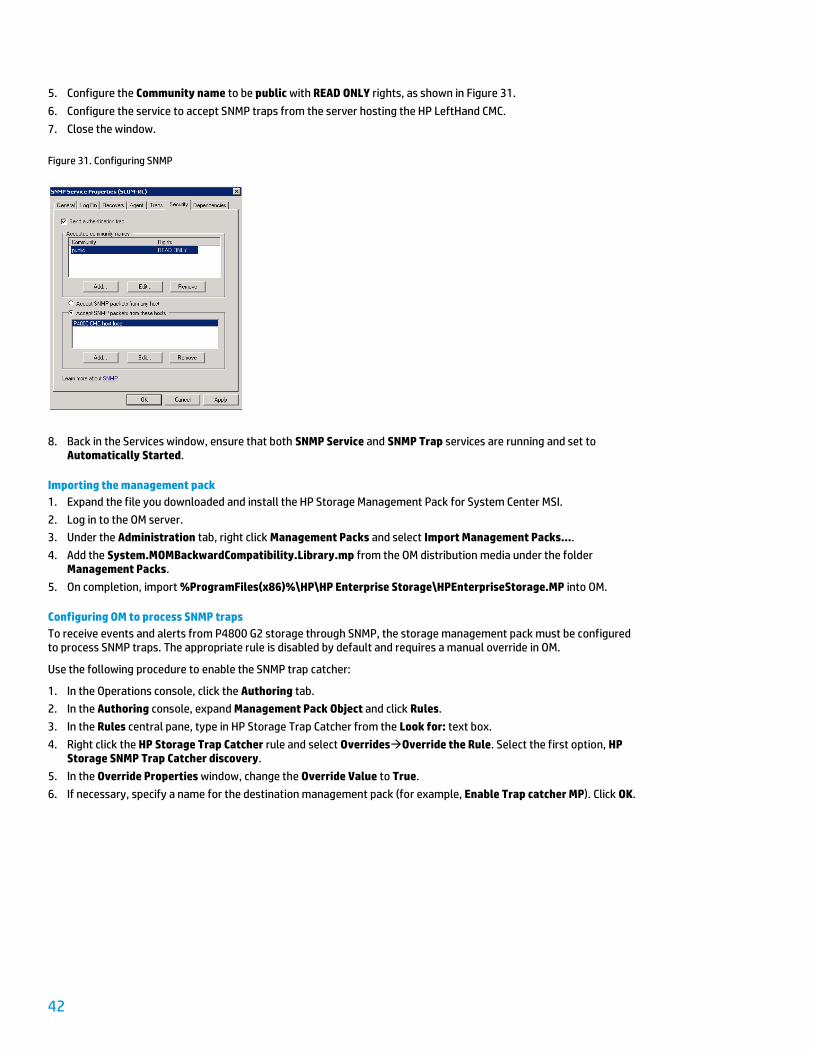
5. Configure the Community name to be public with READ ONLY rights, as shown in Figure 31.
6. Configure the service to accept SNMP traps from the server hosting the HP LeftHand CMC.
7. Close the window.
Figure 31. Configuring SNMP
8. Back in the Services window, ensure that both SNMP Service and SNMP Trap services are running and set to Automatically Started.
Importing the management pack
1. Expand the file you downloaded and install the HP Storage Management Pack for System Center MSI.
2. Log in to the OM server.
3. Under the Administration tab, right click Management Packs and select Import Management Packs….
4. Add the System.MOMBackwardCompatibility.Library.mp from the OM distribution media under the folder Management Packs.
5. On completion, import %ProgramFiles(x86)%\HP\HP Enterprise Storage\HPEnterpriseStorage.MP into OM.
Configuring OM to process SNMP traps
To receive events and alerts from P4800 G2 storage through SNMP, the storage management pack must be configured to process SNMP traps. The appropriate rule is disabled by default and requires a manual override in OM.
Use the following procedure to enable the SNMP trap catcher:
1. In the Operations console, click the Authoring tab.
2. In the Authoring console, expand Management Pack Object and click Rules.
3. In the Rules central pane, type in HP Storage Trap Catcher from the Look for: text box.
4. Right click the HP Storage Trap Catcher rule and select OverridesOverride the Rule. Select the first option, HP Storage SNMP Trap Catcher discovery.
5. In the Override Properties window, change the Override Value to True.
6. If necessary, specify a name for the destination management pack (for example, Enable Trap catcher MP). Click OK.
43
Configuring settings for SNMP traps on P4800 G2 storage
Configuring SNMP traps for P4800 G2 storage is a two-part process whereby you use the CMC to modify settings. First, the SNMP agent is enabled; secondly, the destination for traps is configured.
Use the following procedure to configure SNMP traps:
1. Log in to the server that hosts the CMC.
2. Open the CMC and navigate to the management group for the SAN storage.
3. Enter the credentials of the administrator for this management group.
4. Expand the hierarchy of the group to EventsSNMP.
5. In the right pane, pull down the SNMP Tasks menu and select Edit SNMP General Settings….
6. In the Edit SNMP Settings dialog box, ensure that:
– The agent is enabled.
– The community string is set to public.
7. Click OK to confirm the changes.
8. Click OK on the information dialog box.
9. Back to the CMC console, select Edit SNMP Trap Settings… from the SNMP Tasks menu.
10. If necessary, in the Edit Trap Settings dialog box, set the community string to public.
11. In the Trap recipients list, click Add... and provide the name of the OM server. Leave the V1 trap version as default.
12. Click OK twice to confirm the changes.
13. Click OK on the information dialog box.
14. Back to the CMC console, select Send test Traps from the SNMP Tasks menu. Click OK to confirm the operation.
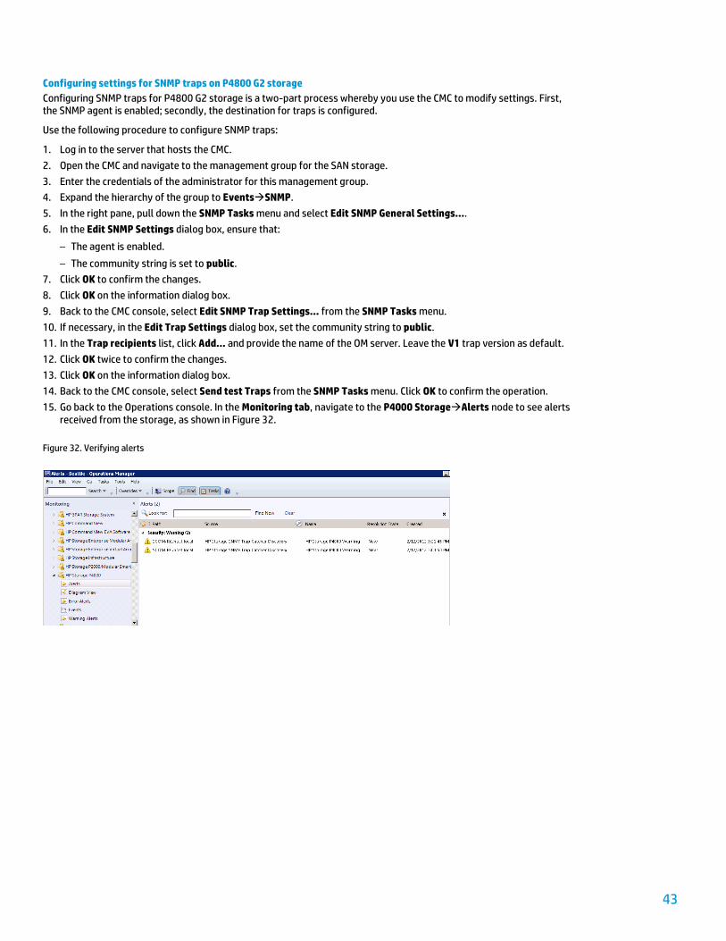
15. Go back to the Operations console. In the Monitoring tab, navigate to the P4000 StorageAlerts node to see alerts received from the storage, as shown in Figure 32.
Figure 32. Verifying alerts
44
Automating the private cloud with System Center 2012 Orchestrator
Automation is one of the key characteristics of a private cloud. For example, process and task automation can help you respond more quickly to changing business demands, thus creating a dynamic infrastructure that scales up or down based on demand, while reducing your overall cost of operations.
Orchestrator, a component of System Center (SC) 2012, provides data center workflow capabilities that allow you to automate the creation, monitoring, and deployment of resources in a private cloud environment. As an example, this section describes how to automate the workflow for adding new compute nodes to the VirtualSystem VS2 solution.
The following tasks are described:
Adding the System Center and third-party integration packs that are necessary to support workflow automation
Creating a workflow to add new compute nodes
Note It is assumed that a SC Orchestrator server is available. For more information on installing SC Orchestrator, refer to http://technet.microsoft.com/en-us/library/hh420337.aspx.
Deploying integration packs
Use the following procedure to install additional integration packs on SC Orchestrator:
1. Download the following integration packs from the TechNet Download Center at http://technet.microsoft.com/en-us/library/hh295851.aspx:
– HP iLO and OA Integration Pack for System Center 2012
– Active Directory Integration Pack for System Center 2012
– Integration Pack for System Center 2012 Virtual Machine Manager
2. Install these kits in local folders on the SC Orchestrator server.
3. Launch the Deployment Manager console of SC Orchestrator.
4. In the left pane window of the console, right click Integration Packs and select Register IP with the Orchestrator Manager Server....
5. Follow the wizard to register all integration pack files (.OIP).
6. Back at the main console, right click Integration Packs and select Deploy IP to Runbook Server or Runbook Designer….
7. Follow the wizard to deploy the registered OIPs to the Runbook designer.
45
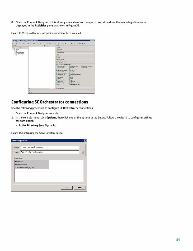
8. Open the Runbook Designer. If it is already open, close and re-open it. You should see the new integration packs displayed in the Activities pane, as shown in Figure 33.
Figure 33. Verifying that new integration packs have been installed
Configuring SC Orchestrator connections
Use the following procedure to configure SC Orchestrator connections:
1. Open the Runbook Designer console.
2. In the console menu, click Options, then click one of the options listed below. Follow the wizard to configure settings for each option.
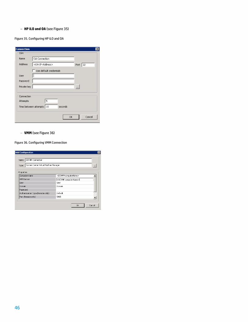
– Active Directory (see Figure 34)
Figure 34. Configuring the Active Directory option
46
– HP iLO and OA (see Figure 35)
Figure 35. Configuring HP iLO and OA
– VMM (see Figure 36)
Figure 36. Configuring VMM Connection
47
Automating the deployment of a new server
Rather than using the VMM console to deploy a new server, you can leverage SC Orchestrator to create a runbook that automates the process, thus eliminating the burden of manually installing servers.
After a new blade has been physically added, the generic flow for deploying this new server is as shown in Figure 37.
Figure 37. Stages in the deployment of a new server
To orchestrate this workflow, HP created the following runbooks using SC Orchestrator:
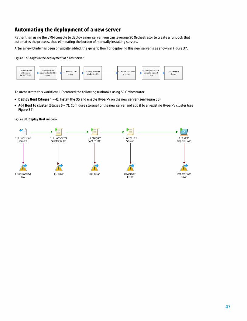
Deploy Host (Stages 1 – 4): Install the OS and enable Hyper-V on the new server (see Figure 38)
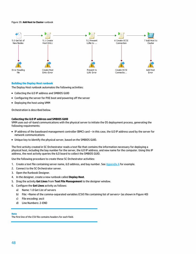
Add Host to cluster (Stages 5 – 7): Configure storage for the new server and add it to an existing Hyper-V cluster (see Figure 39)
Figure 38. Deploy Host runbook
48
Figure 39. Add Host to Cluster runbook
Building the Deploy Host runbook
The Deploy Host runbook automates the following activities:
Collecting the iLO IP address and SMBIOS GUID
Configuring the server for PXE boot and powering off the server
Deploying the host using VMM
Orchestration is described below.
Collecting the iLO IP address and SMBIOS GUID VMM uses out-of-band communications with the physical server to initiate the OS deployment process, generating the following requirements:
IP address of the baseboard management controller (BMC) card – in this case, the iLO IP address used by the server for network communications
Unique key to identify the physical server, based on the SMBIOS GUID.
The first activity created in SC Orchestrator reads a text file that contains the information necessary for deploying a physical host, including the bay number for the server, the iLO IP address, and new name for the computer. Using this IP address, the next activity queries the iLO board to collect the SMBIOS GUID.
Use the following procedure to create these SC Orchestrator activities:
1. Create a text file containing server name, iLO address, and bay number. See Appendix A for example.
2. Connect to the SC Orchestrator server.
3. Open the Runbook Designer.
4. In the designer, create a new runbook called Deploy Host.
5. Drag the activity Get Lines from Text File Management to the designer window.
6. Configure the Get Lines activity as follows:
a) Name: 1.0 Get List of servers
b) File: <Name of the comma-separated variables (CSV) file containing list of servers> (as shown in Figure 40)
c) File encoding: ascii
d) Line Numbers: 2-END
Note The first line of the CSV file contains headers for each field.
49
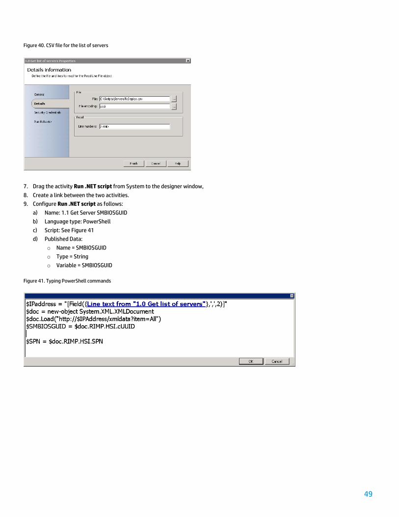
Figure 40. CSV file for the list of servers
7. Drag the activity Run .NET script from System to the designer window,
8. Create a link between the two activities.
9. Configure Run .NET script as follows:
a) Name: 1.1 Get Server SMBIOSGUID
b) Language type: PowerShell
c) Script: See Figure 41
d) Published Data:
o Name = SMBIOSGUID
o Type = String
o Variable = SMBIOSGUID
Figure 41. Typing PowerShell commands
50
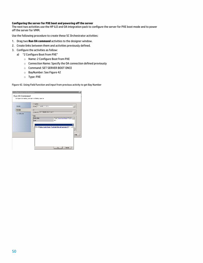
Configuring the server for PXE boot and powering off the server The next two activities use the HP iLO and OA integration pack to configure the server for PXE boot mode and to power off the server for VMM.
Use the following procedure to create these SC Orchestrator activities:
1. Drag two Run OA command activities to the designer window.
2. Create links between them and activities previously defined.
3. Configure the activities as follow:
a) “2 Configure Boot from PXE”
o Name: 2 Configure Boot from PXE
o Connection Name: Specify the OA connection defined previously
o Command: SET SERVER BOOT ONCE
o BayNumber: See Figure 42
o Type: PXE
Figure 42. Using Field function and input from previous activity to get Bay Number
51
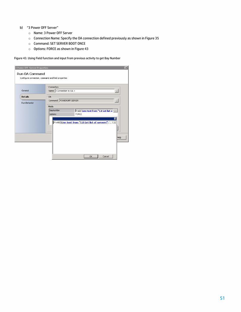
b) “3 Power OFF Server”
o Name: 3 Power OFF Server
o Connection Name: Specify the OA connection defined previously as shown in Figure 35
o Command: SET SERVER BOOT ONCE
o Options: FORCE as shown in Figure 43
Figure 43. Using Field function and input from previous activity to get Bay Number

52
Deploying the host using VMM The last activity consists of executing a PowerShell script on the VMM server to deploy the OS on the physical host. The Run VMM PowerShell script activity from the VMM Integration Pack is used.
Use the following procedure to create the SC Orchestrator activity:
1. Drag the Run VMM PowerShell script activity to the designer window.
2. Create a link to other activities.
3. Configure the activity as follows:
a) Name: 4 VMM Deploy Host
b) Connection Name: Specify the VMM connection defined previously
c) PowerShell script: See Figure 44
d) Output Variable 1: $result
Figure 44. Entering PowerShell commands as required in step 3. c)
The 4 deploy-host.ps1 file (listed in Appendix A) is stored in the VMMLibrary share of the VMM server.
Building the Add Host to Cluster runbook
The Add Host to Cluster runbook automates the following activities:
Getting a list of new nodes
Creating host entries in the SAN management group
Presenting LUNs to the server
Creating an iSCSI connection
Orchestration is described below.
53
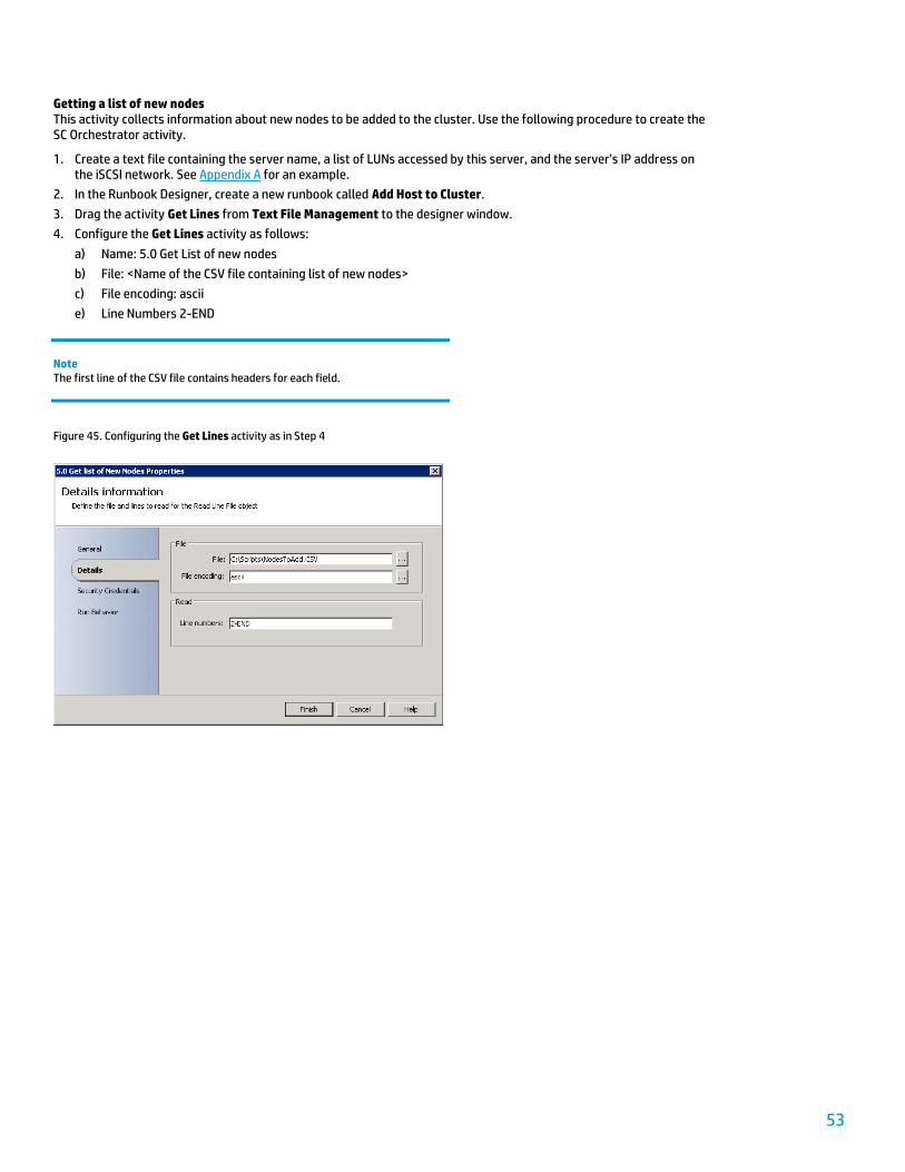
Getting a list of new nodes This activity collects information about new nodes to be added to the cluster. Use the following procedure to create the SC Orchestrator activity.
1. Create a text file containing the server name, a list of LUNs accessed by this server, and the server’s IP address on the iSCSI network. See Appendix A for an example.
2. In the Runbook Designer, create a new runbook called Add Host to Cluster.
3. Drag the activity Get Lines from Text File Management to the designer window.
4. Configure the Get Lines activity as follows:
a) Name: 5.0 Get List of new nodes
b) File: <Name of the CSV file containing list of new nodes>
c) File encoding: ascii
e) Line Numbers 2-END
Note The first line of the CSV file contains headers for each field.
Figure 45. Configuring the Get Lines activity as in Step 4
54
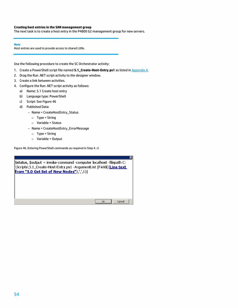
Creating host entries in the SAN management group The next task is to create a host entry in the P4800 G2 management group for new servers.
Note Host entries are used to provide access to shared LUNs.
Use the following procedure to create the SC Orchestrator activity:
1. Create a PowerShell script file named 5.1_Create-Host-Entry.ps1 as listed in Appendix A.
2. Drag the Run .NET script activity to the designer window.
3. Create a link between activities.
4. Configure the Run .NET script activity as follows:
a) Name: 5.1 Create host entry
b) Language type: PowerShell
c) Script: See Figure 46
d) Published Data:
– Name = CreateHostEntry_Status
o Type = String
o Variable = Status
– Name = CreateHostEntry_ErrorMessage
o Type = String
o Variable = Output
Figure 46. Entering PowerShell commands as required in Step 4. c)
55
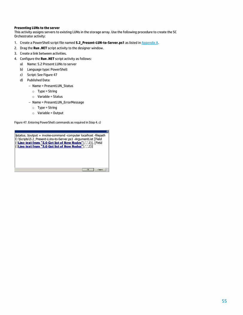
Presenting LUNs to the server This activity assigns servers to existing LUNs in the storage array. Use the following procedure to create the SC Orchestrator activity:
1. Create a PowerShell script file named 5.2_Present-LUN-to-Server.ps1 as listed in Appendix A.
2. Drag the Run .NET script activity to the designer window.
3. Create a link between activities.
4. Configure the Run .NET script activity as follows:
a) Name: 5.2 Present LUNs to server
b) Language type: PowerShell
c) Script: See Figure 47
d) Published Data:
– Name = PresentLUN_Status
o Type = String
o Variable = Status
– Name = PresentLUN_ErrorMessage
o Type = String
o Variable = Output
Figure 47. Entering PowerShell commands as required in Step 4. c)
56
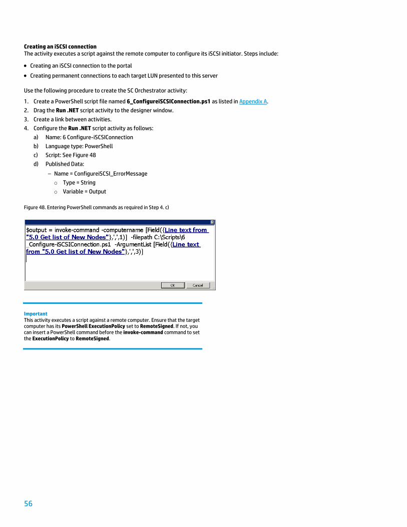
Creating an iSCSI connection The activity executes a script against the remote computer to configure its iSCSI initiator. Steps include:
Creating an iSCSI connection to the portal
Creating permanent connections to each target LUN presented to this server
Use the following procedure to create the SC Orchestrator activity:
1. Create a PowerShell script file named 6_ConfigureiSCSIConnection.ps1 as listed in Appendix A.
2. Drag the Run .NET script activity to the designer window.
3. Create a link between activities.
4. Configure the Run .NET script activity as follows:
a) Name: 6 Configure-iSCSIConnection
b) Language type: PowerShell
c) Script: See Figure 48
d) Published Data:
– Name = ConfigureiSCSI_ErrorMessage
o Type = String
o Variable = Output
Figure 48. Entering PowerShell commands as required in Step 4. c)
Important This activity executes a script against a remote computer. Ensure that the target computer has its PowerShell ExecutionPolicy set to RemoteSigned. If not, you can insert a PowerShell command before the invoke-command command to set the ExecutionPolicy to RemoteSigned.
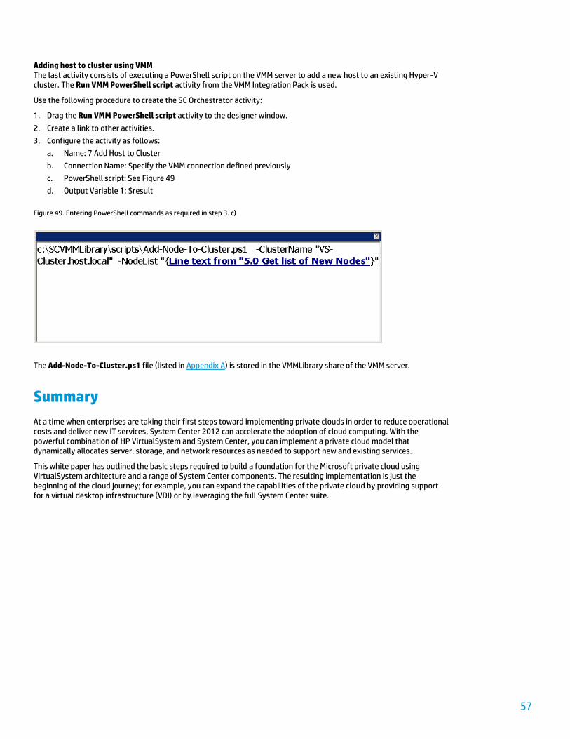
57
Adding host to cluster using VMM The last activity consists of executing a PowerShell script on the VMM server to add a new host to an existing Hyper-V cluster. The Run VMM PowerShell script activity from the VMM Integration Pack is used.
Use the following procedure to create the SC Orchestrator activity:
1. Drag the Run VMM PowerShell script activity to the designer window.
2. Create a link to other activities.
3. Configure the activity as follows:
a. Name: 7 Add Host to Cluster
b. Connection Name: Specify the VMM connection defined previously
c. PowerShell script: See Figure 49
d. Output Variable 1: $result
Figure 49. Entering PowerShell commands as required in step 3. c)
The Add-Node-To-Cluster.ps1 file (listed in Appendix A) is stored in the VMMLibrary share of the VMM server.
Summary
At a time when enterprises are taking their first steps toward implementing private clouds in order to reduce operational costs and deliver new IT services, System Center 2012 can accelerate the adoption of cloud computing. With the powerful combination of HP VirtualSystem and System Center, you can implement a private cloud model that dynamically allocates server, storage, and network resources as needed to support new and existing services.
This white paper has outlined the basic steps required to build a foundation for the Microsoft private cloud using VirtualSystem architecture and a range of System Center components. The resulting implementation is just the beginning of the cloud journey; for example, you can expand the capabilities of the private cloud by providing support for a virtual desktop infrastructure (VDI) or by leveraging the full System Center suite.
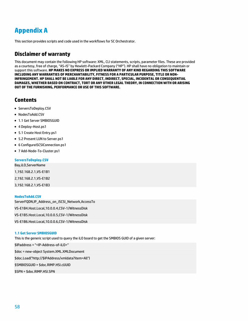
58
Appendix A
This section provides scripts and code used in the workflows for SC Orchestrator.
Disclaimer of warranty
This document may contain the following HP software: XML, CLI statements, scripts, parameter files. These are provided as a courtesy, free of charge, “AS-IS” by Hewlett-Packard Company (“HP”). HP shall have no obligation to maintain or support this software. HP MAKES NO EXPRESS OR IMPLIED WARRANTY OF ANY KIND REGARDING THIS SOFTWARE INCLUDING ANY WARRANTIES OF MERCHANTABILITY, FITNESS FOR A PARTICULAR PURPOSE, TITLE OR NON-INFRINGEMENT. HP SHALL NOT BE LIABLE FOR ANY DIRECT, INDIRECT, SPECIAL, INCIDENTAL OR CONSEQUENTIAL DAMAGES, WHETHER BASED ON CONTRACT, TORT OR ANY OTHER LEGAL THEORY, IN CONNECTION WITH OR ARISING OUT OF THE FURNISHING, PERFORMANCE OR USE OF THIS SOFTWARE.
Contents
ServersToDeploy.CSV
NodesToAdd.CSV
1.1 Get Server SMBIOSGUID
4 Deploy-Host.ps1
5.1 Create Host Entry.ps1
5.2 Present LUN to Server.ps1
6 ConfigureiSCSIConnection.ps1
7 Add-Node-To-Cluster.ps1
ServersToDeploy.CSV
Bay,iLO,ServerName
1,192.168.2.1,VS-E1B1
2,192.168.2.1,VS-E1B2
3,192.168.2.1,VS-E1B3
NodesToAdd.CSV
ServerFQDN,IP_Address_on_iSCSI_Network,AccessTo
VS-E1B4.Host.Local,10.0.0.4,CSV-1/WitnessDisk
VS-E1B5.Host.Local,10.0.0.5,CSV-1/WitnessDisk
VS-E1B6.Host.Local,10.0.0.6,CSV-1/WitnessDisk
1.1 Get Server SMBIOSGUID
This is the generic script used to query the iLO board to get the SMBIOS GUID of a given server:
$IPaddress = "<IP-Address-of-iLO>”
$doc = new-object System.XML.XMLDocument
$doc.Load("http://$IPAddress/xmldata?item=All")
$SMBIOSGUID = $doc.RIMP.HSI.cUUID
$SPN = $doc.RIMP.HSI.SPN
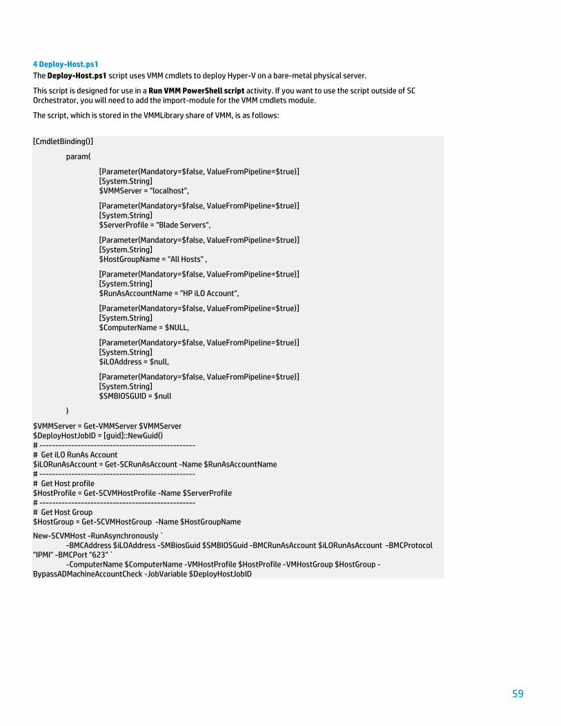
59
4 Deploy-Host.ps1
The Deploy-Host.ps1 script uses VMM cmdlets to deploy Hyper-V on a bare-metal physical server.
This script is designed for use in a Run VMM PowerShell script activity. If you want to use the script outside of SC Orchestrator, you will need to add the import-module for the VMM cmdlets module.
The script, which is stored in the VMMLibrary share of VMM, is as follows:
[CmdletBinding()]
param(
[Parameter(Mandatory=$false, ValueFromPipeline=$true)] [System.String] $VMMServer = "localhost",
[Parameter(Mandatory=$false, ValueFromPipeline=$true)] [System.String] $ServerProfile = "Blade Servers",
[Parameter(Mandatory=$false, ValueFromPipeline=$true)] [System.String] $HostGroupName = "All Hosts" ,
[Parameter(Mandatory=$false, ValueFromPipeline=$true)] [System.String] $RunAsAccountName = "HP iLO Account",
[Parameter(Mandatory=$false, ValueFromPipeline=$true)] [System.String] $ComputerName = $NULL,
[Parameter(Mandatory=$false, ValueFromPipeline=$true)] [System.String] $iLOAddress = $null,
[Parameter(Mandatory=$false, ValueFromPipeline=$true)] [System.String] $SMBIOSGUID = $null
)
$VMMServer = Get-VMMServer $VMMServer $DeployHostJobID = [guid]::NewGuid() # ------------------------------------------------- # Get iLO RunAs Account $iLORunAsAccount = Get-SCRunAsAccount -Name $RunAsAccountName # ------------------------------------------------- # Get Host profile $HostProfile = Get-SCVMHostProfile -Name $ServerProfile # ------------------------------------------------- # Get Host Group $HostGroup = Get-SCVMHostGroup -Name $HostGroupName
New-SCVMHost -RunAsynchronously ` -BMCAddress $iLOAddress -SMBiosGuid $SMBIOSGuid -BMCRunAsAccount $iLORunAsAccount -BMCProtocol "IPMI" -BMCPort "623" ` -ComputerName $ComputerName -VMHostProfile $HostProfile -VMHostGroup $HostGroup -BypassADMachineAccountCheck -JobVariable $DeployHostJobID
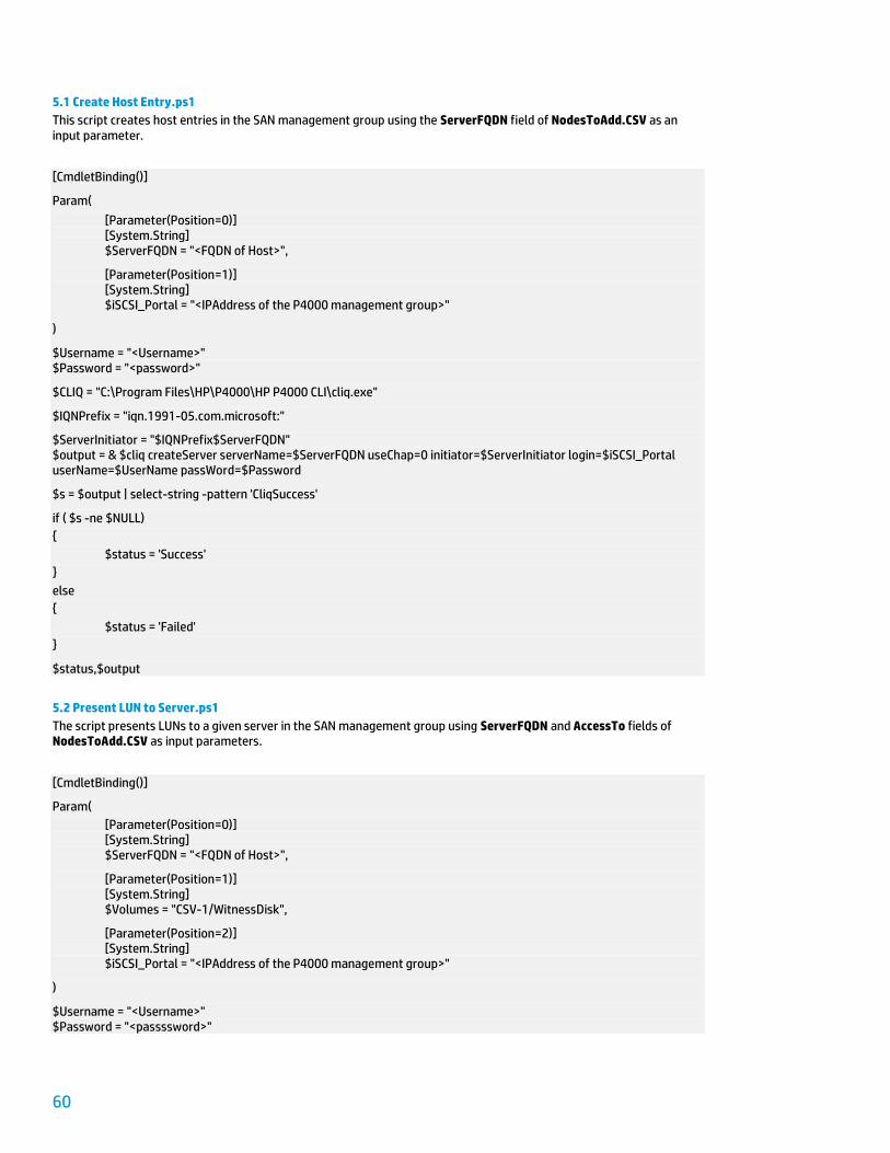
60
5.1 Create Host Entry.ps1
This script creates host entries in the SAN management group using the ServerFQDN field of NodesToAdd.CSV as an input parameter.
[CmdletBinding()]
Param(
[Parameter(Position=0)] [System.String] $ServerFQDN = "<FQDN of Host>",
[Parameter(Position=1)] [System.String] $iSCSI_Portal = "<IPAddress of the P4000 management group>"
)
$Username = "<Username>" $Password = "<password>"
$CLIQ = "C:\Program Files\HP\P4000\HP P4000 CLI\cliq.exe"
$IQNPrefix = "iqn.1991-05.com.microsoft:"
$ServerInitiator = "$IQNPrefix$ServerFQDN" $output = & $cliq createServer serverName=$ServerFQDN useChap=0 initiator=$ServerInitiator login=$iSCSI_Portal userName=$UserName passWord=$Password
$s = $output | select-string -pattern 'CliqSuccess'
if ( $s -ne $NULL)
{
$status = 'Success'
}
else
{
$status = 'Failed'
}
$status,$output
5.2 Present LUN to Server.ps1
The script presents LUNs to a given server in the SAN management group using ServerFQDN and AccessTo fields of NodesToAdd.CSV as input parameters.
[CmdletBinding()]
Param(
[Parameter(Position=0)] [System.String] $ServerFQDN = "<FQDN of Host>",
[Parameter(Position=1)] [System.String] $Volumes = "CSV-1/WitnessDisk",
[Parameter(Position=2)] [System.String] $iSCSI_Portal = "<IPAddress of the P4000 management group>"
)
$Username = "<Username>" $Password = "<passssword>"
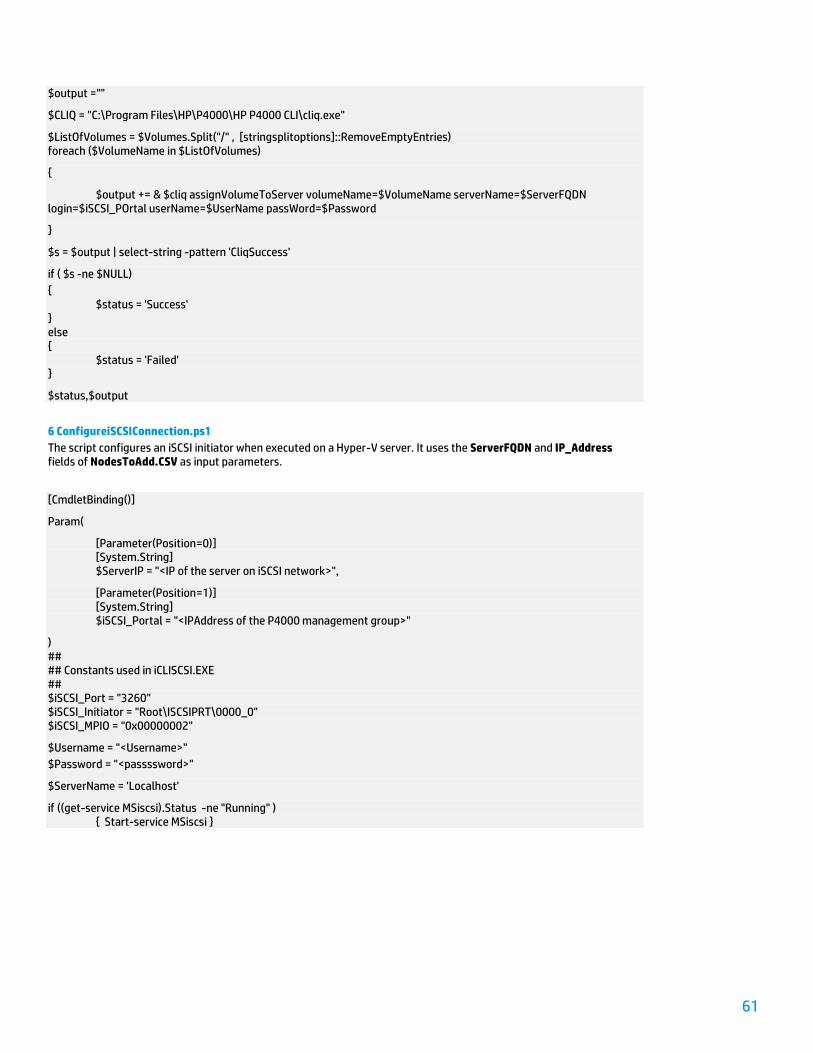
61
$output =""
$CLIQ = "C:\Program Files\HP\P4000\HP P4000 CLI\cliq.exe"
$ListOfVolumes = $Volumes.Split("/" , [stringsplitoptions]::RemoveEmptyEntries) foreach ($VolumeName in $ListOfVolumes)
{
$output += & $cliq assignVolumeToServer volumeName=$VolumeName serverName=$ServerFQDN login=$iSCSI_POrtal userName=$UserName passWord=$Password
}
$s = $output | select-string -pattern 'CliqSuccess'
if ( $s -ne $NULL)
{ $status = 'Success' } else { $status = 'Failed' }
$status,$output
6 ConfigureiSCSIConnection.ps1
The script configures an iSCSI initiator when executed on a Hyper-V server. It uses the ServerFQDN and IP_Address fields of NodesToAdd.CSV as input parameters.
[CmdletBinding()]
Param(
[Parameter(Position=0)] [System.String] $ServerIP = "<IP of the server on iSCSI network>",
[Parameter(Position=1)] [System.String] $iSCSI_Portal = "<IPAddress of the P4000 management group>"
) ## ## Constants used in iCLISCSI.EXE ## $iSCSI_Port = "3260" $iSCSI_Initiator = "Root\ISCSIPRT\0000_0" $iSCSI_MPIO = "0x00000002"
$Username = "<Username>"
$Password = "<passssword>"
$ServerName = 'Localhost'
if ((get-service MSiscsi).Status -ne "Running" ) { Start-service MSiscsi }

62
## Get the iSCSI Initiator's Portal and its port $PortalList = get-wmiobject -ComputerName $ServerName -namespace root\wmi -query "select portalinformation from MSiSCSI_PortalInfoClass" foreach ($Portal in $PortalList.PortalInformation)
{
$PortalIP = ([Net.IPAddress]$Portal.IpAddr.IPV4Address).IPAddresstoString if ($PortalIP -match $ServerIP) { $iSCSIPortID = $Portal.Port }
}
##
## Add Target Portal first
##
iscsicli QAddTargetPortal $iSCSI_Portal
iscsicli refreshtargetportal $iSCSI_Portal $iSCSI_Port
## <Script –Continuation>
## ## Add Target Portal first ## iscsicli QAddTargetPortal $iSCSI_Portal iscsicli refreshtargetportal $iSCSI_Portal $iSCSI_Port
## Get Target IQN ## $ListofTargetsIQN = get-wmiobject -ComputerName $ServerName -namespace root\wmi msiSCSIInitiator_TargetClass | % { $_.targetname}
## ## Create Peristent Login Target ## if ( $ListofTargetsIQN -ne $NULL) { foreach ( $TargetIQN in $ListofTargetsIQN ) { write-verbose "Creating Persistent Login for target $TargetIQN" iscsicli PersistentLoginTarget $TargetIQN T $iSCSI_Portal $iSCSI_Port $iSCSI_Initiator $iSCSIPortID * $iSCSI_MPIO * * * * * * * * * 0 iscsicli LoginTarget $TargetIQN T $iSCSI_Portal $iSCSI_Port $iSCSI_Initiator $iSCSIPortID * $iSCSI_MPIO * * * * * * * * * 0 } } else { write-verbose "List of Targets null" }
##<End-of-Script>
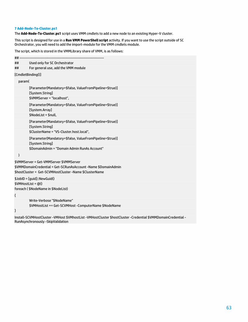
63
7 Add-Node-To-Cluster.ps1
The Add-Node-To-Cluster.ps1 script uses VMM cmdlets to add a new node to an existing Hyper-V cluster.
This script is designed for use in a Run VMM PowerShell script activity. If you want to use the script outside of SC Orchestrator, you will need to add the import-module for the VMM cmdlets module.
The script, which is stored in the VMMLibrary share of VMM, is as follows:
## ------------------------------------------------------------
## Used only for SC Orchestrator
## For general use, add the VMM module
[CmdletBinding()]
param(
[Parameter(Mandatory=$false, ValueFromPipeline=$true)]
[System.String]
$VMMServer = "localhost",
[Parameter(Mandatory=$false, ValueFromPipeline=$true)]
[System.Array]
$NodeList = $null,
[Parameter(Mandatory=$false, ValueFromPipeline=$true)]
[System.String]
$ClusterName = "VS-Cluster.host.local",
[Parameter(Mandatory=$false, ValueFromPipeline=$true)]
[System.String]
$DomainAdmin = "Domain Admin RunAs Account"
)
$VMMServer = Get-VMMServer $VMMServer
$VMMDomainCredential = Get-SCRunAsAccount -Name $DomainAdmin
$hostCluster = Get-SCVMHostCluster -Name $ClusterName
$JobID = [guid]::NewGuid()
$VMHostList = @()
foreach ( $NodeName in $NodeList)
{
Write-Verbose "$NodeName"
$VMHostList += Get-SCVMHost -ComputerName $NodeName
}
Install-SCVMHostCluster -VMHost $VMhostList -VMHostCluster $hostCluster -Credential $VMMDomainCredential -RunAsynchronously -SkipValidation
64
For more information
HP ActiveAnswers www.hp.com/solutions/activeanswers
HP and Microsoft www.hp.com/go/microsoft
HP Converged Infrastructure www.hp.com/go/convergedinfrastructure
HP Insight Control management software www.hp.com/go/insightcontrol
HP ProLiant servers www.hp.com/go/proliant
HP Storage www.hp.com/storage
HP Virtual Connect Technology www.hp.com/go/virtualconnect
HP VirtualSystem www.hp.com/go/Virtualsystem
Microsoft Hyper-V http://www.microsoft.com/windowsserver2008/en/us/hyperv-main.aspx
Microsoft System Center http://www.microsoft.com/systemcenter/en/us/default.aspx
To help us improve our documents, please provide feedback at http://h71019.www7.hp.com/ActiveAnswers/us/en/solutions/technical_tools_feedback.html.
Get connected hp.com/go/getconnected
Current HP driver, support, and security alerts delivered directly to your desktop
© Copyright 2012 Hewlett-Packard Development Company, L.P. The information contained herein is subject to change without notice. The only warranties for HP products and services are set forth in the express warranty statements accompanying such products and services. Nothing herein should be construed as constituting an additional warranty. HP shall not be liable for technical or editorial errors or omiss ions contained herein.
Microsoft and Windows are U.S. registered trademarks of Microsoft Corporation. Intel and Xeon are trademarks of Intel Corporation in the U.S. and other countries.
4AA4-0935ENW, Created April 2012