implementation of tm modeling as an ...members.cgs.ca/documents/conference2006/seatosky/s2/0399...to...
TRANSCRIPT

IMPLEMENTATION OF TM MODELING AS AN ALTERNATIVE FOR FULLY COUPLED THM MODELS Amir H Hosseini, Department of Civil and Environmental Engineering – University of Alberta, Edmonton, Alberta, Canada Peter J Cleall, Geoenvironmental Research Centre – Cardiff University, Cardiff, Wales, UK C Derek Martin, Department of Civil and Environmental Engineering – University of Alberta, Edmonton, Alberta, Canada ABSTRACT Coupled thermal-hydraulic-mechanical (THM) processes under multiphase flow conditions are prevalent in a number of geo-scientific applications. A few of the most important include high-level nuclear waste disposal in geological media, geothermal energy extraction, and enhanced oil recovery. In a high-level nuclear waste, the canister and metal containers form the first barrier, and the surrounding repository soils or rocks form a long-term barrier against contamination. Fully coupled THM models are typically used to study the coupled processes in clay buffers and fractured rocks surrounding waste canisters. In this paper, Thermal-Mechanical (TM) modelling of the in-room emplacement configuration is studied as a much quicker alternative to typical THM modelling to evaluate the stress-strain field in the rock regions. Thermal properties of the sealing materials should be updated using the results of the Thermal-Hydraulic (TH) analyses. The updated properties are incorporated in the TM model to study the performance of the combination of TH and TM modelling as an alternative for fully coupled THM modelling. RÉSUMÉ Les processus (THM) thermique-hydraulique-mécaniques couplés dans des conditions multiphasées d'écoulement sont répandus dans un certain nombre d'applications geo-scientifiques. Quelques uns du plus important incluent la disposition de rebut nucléaire à niveau élevé dans les médias géologiques, l'extraction géothermique d'énergie, et le rétablissement augmenté d'huile. Dans une perte nucléaire à niveau élevé, les récipients de boîte métallique et en métal forment la première barrière, et les sols ou les roches environnantes de dépôt forment une barrière à long terme contre la contamination. Des modèles entièrement couplés de THM sont typiquement employés pour étudier les processus couplés dans des amortisseurs d'argile et des boîtes métalliques de rebut environnantes rompues de roches. Dans ce (TM) modeler de papier et Thermique-Mécanique de la configuration de mise en place de dans pièce est étudié comme alternative beaucoup plus rapide à THM typique modelant pour évaluer le champ de contrainte tension dans les régions de roche. Les propriétés thermiques des matériaux de cachetage devraient être mises à jour en utilisant les résultats des analyses Thermique-Hydrauliques (TH). Les propriétés mises à jour sont incorporées dans le modèle de TM pour étudier l'exécution de la combinaison du TH et du TM modelant comme alternative pour modeler entièrement couplé de THM. 1. INTRODUCTION In a high-level nuclear waste repository, an important issue is the heat release from the waste canisters, which gives rise to strongly coupled thermal-hydraulic-mechanical (THM) processes in clay buffers and fractured rocks surrounding waste canisters. Figure 1 shows this coupled THM behaviour. The temperature gradient is one of the main causes of moisture movement (by diffusion) within a clay buffer. At the same time, the clay swells or shrinks as a function of its water content, causing mechanical deformation and stress changes. Mechanical and hydraulic properties of soils may also change during the heating and cooling cycles. Assessment of engineering response of the barriers to exceptionally high temperatures and large hydraulic gradients requires a thorough understanding of the behaviour of soil-based materials in dry, unsaturated or saturated state. Numerical codes have been widely
applied in geotechnical engineering for analysis of mechanical, hydraulic, thermal and coupled problems. They are commonly used for obtaining stress and displacement distributions, fluid pressure distribution and temperature distribution in soil or rock medium. According to results achieved from in-situ experiments, in selection of a safe and proper design for a deep repository, the in-room emplacement geometry may be preferred rather than the conventional borehole emplacement. In order to assess the performance and safety of a repository with in-room emplacement configuration, a comprehensive research into the short-term, mid-term and long-term performance of the multiple barrier system and the host rock is required. The complexities of the phenomena occurring in the system, due to very high temperature and hydraulic gradients, necessitates an appropriate modelling approach to provide reasonable and accurate predictions for both short-term and long-term responses. Thermo-hydraulic-mechanical modelling has been frequently used to
838
Sea to Sky Geotechnique 2006

investigate the responses of such systems. In this work, Thermal – Mechanical (TM) modelling of the in-room emplacement was performed to study the interaction of heat flow and mechanical responses in the system, regardless of hydraulic field. Basically, TM analysis is much faster, comparing to full THM analysis. Considerable differences are observed in the results of two modelling approaches particularly in the buffer regions. General trend and variations of temperature and mechanical responses, however, can be forecasted reasonably well in the rock regions. Modification and updating of thermal properties of the buffer materials can improve results of the TM model. This updating may be implemented using the results of a parallel Thermal-Hydraulic (TH) model. Figure 1: Thermo-hydraulic-mechanical coupling in fractured rock and clay buffers (Ewen and Thomas 1989) 2. THEORETICAL BACKGROUND Thermal–hydraulic–mechanical behaviour of unsaturated soil is represented by four fully coupled governing equations describing mass, air and heat transfer through a deformable soil. The governing differential equations are developed in terms of four principal variables, namely, pore water pressure, pore air pressure, temperature and deformation. A brief explanation is presented in the following paragraphs. 2.1 Theoretical formulation for moisture transfer Generally speaking, in unsaturated porous media, moisture exists in two forms: a liquid phase which is transmitted through the continuous water-filled space; and as water vapour, which is transported through the continuous air-filled space. The flow of liquid phase is conceived to occur under pressure head gradient, elevation head gradient and thermal gradients, and it is described by generalized Darcy’s law (Matyas and Radhakrishna 1968).
Two mechanisms are predominant in vapour transfer phenomena: diffusive and pressure flows. Pressure flow which is related to bulk air flow in the medium is also dealt with via a generalized Darcy’s law, neglecting elevation head gradient. The equation of vapour diffusion in porous media is introduced by Rollins et al (1954) and Ewan & Thomas (1989). A mass flow factor is also introduced to allow for the mass flow of vapour arising from difference in boundary conditions governing the air and vapour components of the diffusion system (Philip and de Vries 1957). Incorporation of these flow laws and their various elements into a mass conservation equation, and expansion and development of different terms gives the mass conservation equation for moisture flow (Mitchell 2002). 2.2 Theoretical formulation for dry air transfer There are two mechanisms of dry air flow through soil which have been considered in this work. These include bulk flow of air through air filled pores; and movement within the liquid phase as dissolved air. The flow law used to represent bulk air flow through unsaturated soil is Darcy’s empirical equation for fluid flow (Carmon 1956). The driving potential for the air phase is the gradient of air pressure. The dissolved air is transferred within the pore liquid. The portion of air which is dissolved in the pore liquid is determined by Henry’s law. Considering the law of conservation of mass, the contribution from the bulk flow of air and the flow of air dissolved in pore liquid are combined into one expression for dry air flow (Mitchell 2002). 2.3 Theoretical formulation for heat transfer The formulation for heat transfer utilizes the three principal modes of heat transmission: conduction, convection and latent heat of vaporisation. The effects of heat radiation are assumed to be negligible. According to the law of conservation of energy for heat flow, the temporal derivative of heat content, Ω, is equal to the spatial derivative of heat flux, Q. This may be expressed as:
( )( )VQ
t
V∂−∇=
∂
∂Ω∂ (1)
The heat content of moist soil per unit volume assumed to be the sum of soil heat storage capacity and the contribution resulting from the latent heat of vaporisation. It is defined as:
( )varc LnSTTH ρ+−=Ω (2)
where Hc is heat capacity of the soil and L is the latent heat of vaporisation. The heat capacity of the soil, Hc, at the reference temperature, Tr, is given as:
( ) ( )daapdavapvllplspsc SCSCSCnCnH ρρρρ +++−= 1
(3)
in which, Cps is the specific heat capacity of solid particles, Cpl is the specific heat capacity of liquid Cpv is the specific
THERMAL (Heat flow
due to heat release of
radioactive waste)
HYDRAULIC
(Groundwater flow
through rock matrix
and fractures
MECHANICAL
(Deformation of
rock matrix and
rock fractures)
water flow heat
convection
mechanical
energy
conversion
thermal
stress
water
pressure
change of
porosity and
apertures
839
Sea to Sky Geotechnique 2006

heat capacity of vapour, Cpda is the specific heat capacity of dry air, and ρs is the density of solid particles. The heat flux per unit area, Q, is determined by:
( )
( )( )rdaapdavapvlvpvllpl
vvlvT
TTvCvCvCvC
LvvTQ
−+++
+++∆−=
ρρρρ
ρρλ (4)
where λT is the coefficient of thermal conductivity of unsaturated soil. Equation (4) shows heat flux comprising of the following mechanisms of heat flow: conduction, convection, and latent heat flow, which is associated with movement of vapour. The coefficient of thermal conductivity, λT, of unsaturated soil has been found to be a function of degree of saturation. Its magnitude rises with an increase in degree of saturation. Incorporating equations (2), (3) and (4) into equation (1) gives the governing differential equation for conservation of energy, in terms of primary variables (Mitchell 2002). 2.4 Theoretical formulation for deformation Deformation of unsaturated soil is described by a constitutive relationship linking stress to strain, suction and temperature via a non-linear elastic constitutive stress-strain theory. The incremental change in elastic volumetric strain is the sum of the strain components attributed to the applied stress increment, to the suction increment (Alonso et al 1988), and to the temperature increment (Pollock 1986). The generalized Hook’s law is used to establish the constitutive non-linear elastic stress-strain relationship. The increment of strain apportioned to an incremental change in net stress is written as:
( )nsns dDd σε 1−= (5)
in which, D is the elastic constitutive matrix and subscript ns refers to net stress. Re-expressing equation (5) gives:
Tsns dddd εεεε −−= (6)
Subscripts s and T refer to suction and temperature. The elastic deformation behaviour of unsaturated soil, at a constant suction, due to changes in net stress can be observed in the compression curves shown in figure 2.
Figure 2: Idealized isotropic compression and recompression curves (Atkinson 1993)
These curves show that on swelling and recompression the behaviour of the soil is elastic. The slope of the virgin compression curve has a value of -λ and recompression slope a value of -κ, while κ is called elastic stiffness parameter for changes in net stress. From this an expression for the change in specific volume due to incremental stress changes at a constant suction can be given as (Alonso 1990):
p
dpdv κ−= (7)
This can be developed to give an expression for the incremental elastic volumetric strain component due to incremental net stress changes as:
p
dp
vd ns
κε −= (8)
Alonso et al (1990) extended this approach and defined the incremental elastic volumetric strain component due to incremental suction changes, at a constant stress as
( )dsD
ps
ds
vd s
atm
ss =
+−=
κε (9)
where elastic stiffness parameter for changes in suction, κs, is the slope of the volume-suction curve in the elastic region. The atmospheric pressure, patm, has been introduced to avoid infinite values of strain, as suction approaches zero. The elastic volumetric strain due to non-uniform temperature distribution may be defined using the coefficient of thermal expansion (Wang 1953), (Boresi 1987). The magnitude of this coefficient is strongly linked to both thermal loading history, degree of liquid saturation, cohesiveness and porosity. Considering the changes in suction with temperature and equation (9) to account for suction effects, the volumetric strain associated with non-uniform temperature may be written in vector form as
( )dTDDT
SDdT
vd sTT
rsT +=
∂
∂+−=
0
αε (10)
in which, α is the coefficient of thermal expansion, Sr is suction at the reference temperature Tr. The soil is assumed to be thermally isotropic body. The coefficient of thermal expansion for a soil body is assumed to comprise the sum of the magnitude of volume change of each constitute, per unit change in temperature. The bulk coefficient of thermal expansion may therefore be written as
( )stggllsbulk nnn ααααα +++−= ..1.
(11)
where, n is porosity, ng is air porosity, nl is water porosity, α with subscripts denotes the thermal expansion of the
v
ln p (net stress)
840
Sea to Sky Geotechnique 2006

solid, water and air and αst is the coefficient of thermal expansion for the soil structure. Elastic deviatoric strains are considered independently of elastic volumetric deformations. The magnitude of elastic shear strain, κs, induced by an increment of deviatoric stress in an isotropic soil is obtained from expression (Atkinson 1993), (Wood 1990):
dqG
d q3
1
=ε (12)
where, q is deviatoric stress and G is shear modulus. The effect of deviatoric stress on volume strains, induced by changes in suction and temperature are not included in this theory. Substitution of equations (9) and (10) into equation (6) provides the constitutive stress-strain equation which, in turn, gives the expression for stress equilibrium. The set of mass conservation equations for moisture and air, together with equation of conservation of energy and stress equilibrium equation define complete formulation of coupled flow and elastic deformation of an unsaturated soil. Each of the four equations comprise only four variables, namely pore water pressure (ul), pore air pressure (ua), absolute temperature (T) and deformation (u). In order to solve the complex form of non-linear theoretical formulation a numerical solution procedure is applied, which simultaneously solves the set of fully coupled governing differential equations. Finite Element Method (FEM) is employed to spatially discretise the equations. The numerical procedure used in development of COMPASS (a software used in this work to model THM and TM behaviour of unsaturated soils) employs a two-dimensional parabolic element with eight nodes. A finite difference time-stepping algorithm is also used to achieve temporal discretization. 3. IN – ROOM EMPLACEMNENT GEOMETRY The in–room emplacement geometry which has been proposed by AECL comprises a single tunnel with six canisters positioned at the mid-height of the tunnel. A cross-section of the proposed in–room emplacement taken through a single in – room emplacement is shown in figure 3. The emplacement consists of a number of engineered barriers. The ‘copper canister’ forms the first engineered barrier. Each canister is surrounded by ‘inner buffer’, which forms the second engineered barrier and its thickness should not be less than 0.25 m at any section. Both of the canisters and inner buffers around them are placed in a soil barrier which is a mixture of bentonite and sand and is called ‘outer buffer’. The outer buffer rests on the ‘dense backfill’, comprising a clay-sand mixture, and is capped by ‘light backfill’. On the lower surface of the cavity the dense backfill is supported by a layer of high performance concrete.
The emplaced materials are contained within a cavity excavated in host granite. By defining the inner Excavation Damaged Zone (inner–EDZ) of host granite rock, and outer Excavation Damaged Zone (outer-EDZ) of host granite rock, the effects of excavations on the structure of host rock are also considered. The distance between each of two adjacent canisters originally is equal to 2.54 m. The repository is considered to be placed in the depth of 100 m and an assumed surface temperature of 13˚C. Beyond 10,000 years, the assumed surface temperature shall be reduced to 0˚C to account for continental glaciations. Figure 3: Schematic cross-section of single in – room emplacement (Thomas et al 2003) The composition of each of the soil based emplaced materials is engineered to enable them to effectively isolate the high-level radioactive waste. Through extensive laboratory investigations, optimum composition for these materials has been determined by Yong et al. (1986) and Radhakrishna et al (1989). The supplied ratio of clay content for each of the in–room emplacement soil based materials is considered to be that which provides optimum value of hydraulic conductivity, dry density, thermal conductivity and compressibility (McEvoy 1997). 3.1 Inner buffer The inner buffer material has been considered to be 100% bentonite material. The initial porosity and initial degree of saturation of inner buffer are 0.41 and 0.6, respectively. Moreover, its density in dry, as placed and saturated conditions is equal to 1610, 1840 and 2010 kg/m3, respectively. The selection of bentonite as a suitable candidate buffer material is based on extensive experimental investigations. For example, the capacity of bentonite swells during hydration and subsequently experiences a reduction in hydraulic conductivity.
Inner Buffer(0.25 m thick)
Container(1.2 m OD, 0.025 m thick)
Gap Backfill(0.04 m thick)
Dense backfill
Concrete
EDZ inner
EDZ outer
Lightbackfill
Rock
Center notch
EDZ inner
EDZ outer
0.50 m
Center notch
0.3 m
2.10
m
0.5 m
0.5 m
1.0 m
0.2 m
0.3 m
1.0 m
0.2 m
1.27 m
1.2 m
1.2 m
Outer Buffer(min 0.25 m thick)
2.10
m
3.57 m
1.0 m
841
Sea to Sky Geotechnique 2006

Hydraulic conductivity of unsaturated clay is a function of degree of saturation and temperature. The thermal conductivity of the inner buffer in dry, as placed and saturated conditions is equal to 0.3, 0.95 and 1.25 W/m.K, respectively. The thermal conductivity of inner buffer together with outer buffer, dense backfill and light backfill vary with degree of saturation, these variations in thermal conductivity, which crucially affect the performance of the system in dissipation of thermal energy, are shown in figure 4. The specific heat capacity of inner buffer in dry, as placed and saturated condition is equal to 880, 1290 and 1520 J/kg.K, respectively.
0
0.5
1
1.5
2
2.5
0 0.2 0.4 0.6 0.8 1 1.2
Degree of Saturation
Th
erm
al
Co
nd
uc
tiv
ity
(W
/m.K
)
Inner buffer
Light backfill
Outer buffer
Dense backfill
Figure 4: Variations in thermal conductivity with degree of saturation for Inner buffer, Outer buffer, Dense backfill and Light backfill (Thomas et al 2003) A non-linear elastic model has been used to model the mechanical behaviour of the inner buffer. In this regard κ, the elastic stiffness parameter for changes in net stress, κs, elastic stiffness parameter for changes in suction, and G, shear modulus, are assumed to be equal to 0.17, 0.094 and 10 MPa, respectively (after Börgesson et al (1996)). 3.2 Outer buffer The Outer buffer material has been assumed to be the same as 50:50 sand-bentonite buffer material used in AECL Buffer/Container Experiment (Mitchell 2002). This buffer material consists of a 50:50 mixture (by dry weight) of silica sand and sodium bentonite mixed with water. The sand used is a well-graded fine to medium silica mixture. The clay used is a powder produced by drying and grinding a natural sodium-based bentonite. The outer buffer has a density in dry, as placed and saturated conditions equal to 1690, 1980 and 2060 kg/m3, respectively. The thermal conductivity of the outer buffer in dry, as placed and saturated conditions is equal to 0.7, 1.7 and 1.7 W/m.K, respectively. As explained above, the thermal conductivity of outer buffer varies with degree of saturation, the changes in thermal conductivity with
degree of saturation of outer buffer is shown in figure 4. The specific heat capacity of outer buffer in dry, as placed and saturated condition is equal to 870, 1350 and 1460 J/kg.K, respectively. To model the mechanical behavior of outer buffer, a non-linear elastic model has been used. In this regard κ, the elastic stiffness parameter for changes in net stress, κs, elastic stiffness parameter for changes in suction, and G, shear modulus, are assumed to be equal to 0.0125, 0.0111 and 10 MPa, respectively (Thomas et al 2003).
3.3 Gap backfill The gap backfill material has been assumed to be the same as outer buffer, a 50:50 sand-bentonite buffer material used in AECL Buffer/Container Experiment. As a result, the Hydraulic, Thermal and Mechanical material properties of the gap are considered to be the same as outer buffer. 3.4 Dense backfill The dense backfill is considered to be 5:25:70 Bentonite:Lake Clay:Aggrigate mix. The initial porosity and initial degree of saturation of dense backfill are 0.22 and 0.8, respectively. Its density in dry, as placed and saturated conditions is equal to 2120, 2280 and 2330 kg/m3, respectively. The thermal conductivity of the dense backfill in dry, as placed and saturated conditions is equal to 1.0, 2.0 and 2.0 W/m.K, respectively. The thermal conductivity of dense backfill varies with degree of saturation, this variation in thermal conductivity, which crucially affects the performance of the system in dissipation of thermal energy, is shown in figure 4. The specific heat capacity of inner buffer in dry, as placed and saturated condition is equal to 860, 1100 and 1160 J/kg.K, respectively. A non-linear elastic model has been used to model the mechanical behavior of the dense backfill. In this regard κ, the elastic stiffness parameter for changes in net stress is considered to be equal to 0.01, κs, elastic stiffness parameter for changes in suction is assumed to be equal to 0.01 and G, shear modulus, is considered to be equal to 10 MPa (Thomas et al 2003). 3.5 Light backfill The light backfill is considered to be 50:50 Bentonite:Sand mix. The initial porosity and initial degree of saturation of light backfill are 0.55 and 0.33, respectively. Moreover, its density in dry, as placed and saturated conditions is equal to 1240, 1400 and 1780 kg/m3, respectively. The thermal conductivity of the light backfill in dry, as placed and saturated conditions is equal to 0.5, 0.7 and 1.4 W/m.K, respectively. The thermal conductivity of light backfill varies with the degree of saturation; this variation in thermal conductivity is shown in figure 4. The specific heat capacity of inner buffer in dry, as placed and saturated condition is equal to 900, 1280 and 1870 J/kg.K, respectively.
842
Sea to Sky Geotechnique 2006

0
200
400
600
800
1000
1200
0 200 400 600 800 1,000
Time (years)P
ow
er
(W)
Full power (W)
Reduced power (W)
In order to model the mechanical behaviour of the light backfill, a non-linear elastic model has been used. In this regard κ, the elastic stiffness parameter for changes in net stress, is considered to be equal to 0.01; κs, elastic stiffness parameter for changes in suction is assumed to be equal to 0.01 and G, shear modulus, is considered to be equal to 10 MPa.
Material Thermal
conductivity (W/m.K)
Heat capacity (J/kg.K)
Density (kg/m3)
Saturated hydraulic
conductivity (m/s)
Host rock 3.0 845 2700 1.0 × 10⁻¹²
EDZ rock,
inner 3.0 845 2700 1.0 × 10⁻¹⁰
EDZ rock, outer
3.0 845 2700 1.0 × 10⁻¹¹
EDZ rock, notch
3.0 845 2700 1.0 × 10⁻⁷
Table 1: Thermal properties and hydraulic conductivity of the host rock and EDZ regions 3.6 The host rock According to previous modelling work on the in–room emplacement configuration (Thomas et al 2003), the granite host rock is assumed to be similar to that found in the Lac du Bonnet granite batholith found at AECL’s underground research laboratory. For the EDZ (Excavation Disturbed Zone) areas, which have been shown in figure 3, the relationships have been modified to reflect the increased porosity and permeability. Density, saturated hydraulic conductivity, thermal conductivity and specific heat capacity of granite host rock, and also inner, outer and notch EDZ rock have been summarized in table 1. In this work, a linear elastic model has been used to define the mechanical behavior of granite rock. In this regard, young’s modulus (E) and shear modulus (G) are considered to be 57 and 24 GPa, and Poisson’s ration (ν ) is 0.21. Moreover, it has been assumed the uniaxial compressive strength of the granite rock material to be 167 MPa and its coefficient of thermal expansion is 7 × 10⁻⁶ /K (Thomas et al 2003); and it has been assumed that the deformation caused by changes in suction, in the granite rock, is negligible. Furthermore, the initial values of stress within the granite rock are considered to be:
MPa30
1
=σ ,
MPa15
2
=σ and
MPa13
3
=σ
3.7 Concrete In this study concrete is considered to be from the type Low-Heat High-Performance Concrete (LHHPC). As input data in the numerical model, the initial porosity and initial degree of saturation of LHHPC are assumed to be 0.15 and 0.5, respectively. Moreover, its density is equal to 2430 kg/m3. The saturated hydraulic conductivity for the concrete is considered to be equal to 1.0 × 10⁻¹² m/s. Similar to granite rock, a linear elastic model is used to model the mechanical behaviour of concrete. In this
regard, young’s modulus (E) and shear modulus (G) are considered to be 36 and 14 GPa, and Poisson’s ration (ν) is 0.3. Moreover, it has been assumed that the coefficient of thermal expansion of concrete to be 1 × 10⁻⁵ /K (Thomas et al 2003). It should be noted that a very little deformation caused by changes in suction is expected within the chamber sand; so, the elastic stiffness parameter for changes in suction of the soil can be set to a negligible value. Figure 5: Variation of container heat output with time (Thomas et al 2003) 3.8 Copper The copper, which is placed as container of the high-level nuclear waste, is considered in the numerical model as an impermeable rigid material. The density of the copper is 8930 kg/m3; and it has a thermal conductivity of 380 W/m.K and a specific heat capacity of 390 J/kg.K. Moreover, its thermal diffusivity is equal to 3552 m2/a. 3.9 Heat power generation The used fuel container is a rigid, right cylinder with a nominal outside diameter of 1162 mm and overall length of 3958 mm. It accommodates 324 fuel bundles which act as a thermal source in the In-Room emplacement configuration. The thermal energy varies with time to represent the decay in heat energy generation expected from the emplaced canisters (Figure 5). Because in this study the in – room emplacement configuration is simulated in a 2-D space, the heat power for canister has been reduced to account for the finite length of canisters and their longitudinal spacing. 4. MODELING THERMAL-MECHANICAL RESPONSE
OF IN – ROOM EMPLACEMENT GEOMETRY COMPASS which simulates two-phase (gas and liquid) fluid flow with two components (air and moisture) in partially saturated soil coupled with heat transport and mechanical responses has been used to model thermo-mechanical responses of AECL-type in-room emplacement configuration. Basically, this model was developed based on Philip and de Vries’ classical approach to moisture movement under thermal gradient
843
Sea to Sky Geotechnique 2006
(Thomas et al 1994) with consideration of gas phase movement and mechanical deformation. The mechanical behaviour in COMPASS is governed either by a state surface approach (Preece 1975) or more recent elasto-plastic approach by Lloret and Alonso (1985). Development of the theoretical model started based on fully coupled model for heat, moisture and air transfer developed by Thomas and Sansom (1995). Non–linear elastic and elasto–plastic deformation was integrated by Thomas and He (1995). The theory is expressed in terms of four coupled governing equations for heat, moisture and air flow, and deformation. More recently, Thomas and Cleall [57] extended the THM model to simulate the behaviour of highly expansive clay.
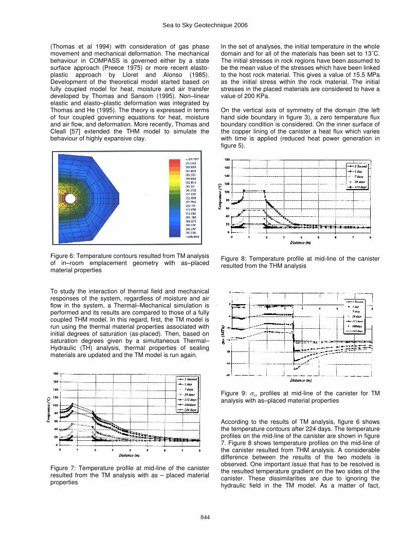
Figure 6: Temperature contours resulted from TM analysis of in–room emplacement geometry with as–placed material properties To study the interaction of thermal field and mechanical responses of the system, regardless of moisture and air flow in the system, a Thermal–Mechanical simulation is performed and its results are compared to those of a fully coupled THM model. In this regard, first, the TM model is run using the thermal material properties associated with initial degrees of saturation (as-placed). Then, based on saturation degrees given by a simultaneous Thermal–Hydraulic (TH) analysis, thermal properties of sealing materials are updated and the TM model is run again. Figure 7: Temperature profile at mid-line of the canister resulted from the TM analysis with as – placed material properties
In the set of analyses, the initial temperature in the whole domain and for all of the materials has been set to 13˚C. The initial stresses in rock regions have been assumed to be the mean value of the stresses which have been linked to the host rock material. This gives a value of 15.5 MPa as the initial stress within the rock material. The initial stresses in the placed materials are considered to have a value of 200 KPa. On the vertical axis of symmetry of the domain (the left hand side boundary in figure 3), a zero temperature flux boundary condition is considered. On the inner surface of the copper lining of the canister a heat flux which varies with time is applied (reduced heat power generation in figure 5). Figure 8: Temperature profile at mid-line of the canister resulted from the THM analysis Figure 9: σxx profiles at mid-line of the canister for TM analysis with as–placed material properties According to the results of TM analysis, figure 6 shows the temperature contours after 224 days. The temperature profiles on the mid-line of the canister are shown in figure 7. Figure 8 shows temperature profiles on the mid-line of the canister resulted from THM analysis. A considerable difference between the results of the two models is observed. One important issue that has to be resolved is the resulted temperature gradient on the two sides of the canister. These dissimilarities are due to ignoring the hydraulic field in the TM model. As a matter of fact,
844
Sea to Sky Geotechnique 2006

variations in thermal conductivity and heat capacity of sealing materials due to changes in their saturation degrees are neglected. For example, due to drying effects, there is a significant reduction in the value of thermal conductivity of buffer materials due to high temperatures. This reduction is missed in the TM model which results in a considerable decrease in the peak temperature. Comparing tensile stresses in the system resulted from the TM analysis (figure 9) and those resulted from THM analysis (figure 10), it is observed that the predicted stresses by two models are reasonably close in the rock regions (x > 5.0 m). Figure 10: σxx profiles at mid-line of the canister for TM analysis with as–placed material properties Figure 11: Temperature profile at mid-line of the canister resulted from the TM analysis with modified material properties Neglecting the variations in thermal properties of the placed materials in TM analysis results in unrealistic temperature profiles. In this regard, thermal properties of the placed materials are updated, based on a hydraulic field resulted from a simultaneous thermal–hydraulic analysis. Thermal conductivity of each of the placed materials is a function of the degree of saturation (figure 4). It increases with an increase in the degree of saturation and vice versa. In the real cases, due to high temperatures around the canister, there is a reduction in degree of saturation of buffer material causing the thermal conductivity of the material to reduce. In order to consider this reduction, the minimum nodal value of degree of saturation in each of the placed materials in each step is obtained from the TH analysis and associated thermal conductivity is calculated using figure 4. Then, for each of placed materials, an average over the thermal
conductivities calculated for different time steps is made. This updated value for thermal conductivity of each of the placed materials together with the original (as-placed value) is presented in table 2. As the light backfill re-saturates (due to recharge from host rock), the updated value for its thermal conductivity is slightly higher than its original value. Figure 12: σxx profiles at mid-line of the canister for TM analysis with modified material properties Heat capacity is a function of degree of saturation. The relationship between heat capacity of the soil and its degree of has been presented in equation (3). In the TM analysis, heat capacity of the soil is calculated just based on the specific heat capacity of soil particles:
spsc CH ρ= (13)
Thus, to obtain more accurate results for temperature distribution, the specific heat capacities used in the TM analysis must be modified and updated by considering the wetting and drying effects in the various placed materials in different time steps. According to results of the simultaneous TH analysis, the minimal nodal value of saturation degree in each of the materials is used to calculate heat capacity, Hc, of each of the placed materials (equation 3). Then, by using equation 13, the updated specific heat capacities, Cps, for each of placed materials, are calculated for different time steps and are averaged to give a single value for each of placed materials. As-placed and updated values for specific heat capacities of various placed materials have been presented in table 2. After determination of modified thermal conductivity and modified specific heat capacity of each of the sealing and backfilling materials, they are used in a new set of TM analyses. The resulted temperature profiles on the mid-line of the canister have been shown in figure 11. Comparing figures 7 and 11, in TM model with modified thermal properties, there is about 14˚C increase in temperature around the canister. This increase in temperature could be predicted before. It is a result of reduction in thermal conductivity and specific heat capacity of the buffer materials. However, in backfill materials, EDZ regions and the host granite rock, temperature profiles resulted from the modified model is the same as the original model. This is due to minimal differences between the original and the modified thermal properties in these regions.
845
Sea to Sky Geotechnique 2006

As-placed
Conductivity (W/m.K)
Updated Conductivity
(W/m.K)
As-placed Heat capacity
(m2/s.K)
Updated Heat
capacity (m2/s.K)
Inner buffer 0.95 0.63 1290 1108
Outer buffer 1.7 1.28 1350 1277
Dense Backfill 2.0 1.82 1100 1137
Light Backfill 0.7 0.73 1280 1276
Table 2: As-placed and updated thermal conductivities and specific heat capacities for various placed materials Induction of stress in the system, due to thermal loading has been shown in figure 12. It is observed that in the TM model with modified thermal property, higher compressive stresses have been induced to the system, around the canister and in the buffer and backfilling materials. Also, larger differences between induced stresses on the two sides of the canister have been observed. Both of these observations can be explained to be due to presence of higher temperatures in the buffer and backfilling materials, which results in higher thermal expansion in these regions. This higher level of thermal expansion, in turn, causes higher induced stresses in the placed materials. Although the induced stresses are slightly higher around the canister and in the buffer materials, the mechanical response of the updated TM model is almost the same as the model with as-placed thermal properties in EDZ regions and host rock. Thus, modifying and updating the thermal properties of placed materials do not make such a considerable difference on the results of the TM model in the rock regions. 5. CONCLUSIONS Comparing to THM analysis, TM analysis is much quicker, requires much less CPU time and numerically is more stable. The TM analysis is an efficient method in evaluation of overall performance of the repository in dissipation of thermal energy as well as mechanical responses of the system in rock regions. However, due to dependency of thermal and mechanical properties of the materials on the hydraulic parameters of the system, application of the TM model in the prediction of responses of the system has limitations. Parameters such as thermal conductivity or heat capacity of each of placed materials are dependent on the hydraulic properties of the system and must be updated to come up with reasonable representation of thermal and mechanical responses of the system. References Alonso, E.E., Battle, F., Gens, A. and Lloret A. 1988. Consolidation analysis of partially saturated soils. Application to earth dam construction. Proc. Int. Conf. on Numerical Methods in Geotechnics. Innsbruck, pp. 1303 -1308.
Alonso, E.E., Gens, A. and Josa, A. 1990. A constitutive model for partially saturated soils. Geotechnique, pp. 405 - 430. Atkinson, J. 1993. An introduction to the mechanics of soils and foundations. McGraw-Hill. Boresi, A.P. and Chong K.P. 1987. Elasticity of Engineering materials. Elsevier. Borgesson, L., Karnland, O. and Johannesson, L.E. 1996. Modeling of the physical behavior of clay barriers close to water saturation. Engineering Geology, 41, pp. 127 - 144. Carmon, P.C. 1956. Flow of gases through porous media. Butterworth Scientific Publications, London, pp. 97-111. Ewen, J. and Thomas, H.R. 1989. Heating unsaturated medium sand. Geotechnique, 39, pp. 455 - 470. Lloret, A. and Alonso, E.E. 1985. State surfaces for partially saturated soils. Proceeding of the 11
th
International Conference on Soil Mechanics and Foundation Engineering, San Francisco, pp. 557 - 562. Matyas, E.L. and Radhakrishna, H.S. 1968. Volume change characteristics of partially saturated soils. Geotechnique, 18, pp. 432 - 448. McEvoy, J.M. 1997. Simulation of the coupled thermal, hydraulic and mechanical behavior of unsaturated soil, using a non-linear elastic constitutive relationship. PhD Thesis. Cardiff University, United Kingdom. Mitchell, H.P. 2002. A study of the Thermo-Hydro-Mechanical behavior of two large-scale in-situ experiments. PhD Thesis. Cardiff University, United Kingdom. Philip, J.R. and de Vries, D.A. 1957. Moisture movement in porous materials under temperature gradients. American Geophysical Union, Transaction 38, pp. 222 - 232. Pollock, D.W. 1986. Simulation of fluid flow and energy processes associated with high-level radioactive waste disposal in unsaturated alluvium. Water Resources Research 22, pp. 765 - 775. Preece, R.J. 1975. The measurement and calculation of physical properties of cabble bedding sands. Part 2; specific thermal capacity, thermal capacity, thermal conductivity and temperature ratio across air-filled pores. C.E.G.B. Laboratory Note No. RD/L/N 231/74. Radhakrishna, H.S., Chan, H.T. Crawford, A.M. and Lau, K.C. 1989. Thermal and physical properties of candidate buffer materials for nuclear fuel waste disposal vault. Canadian Geotechnical Journal, pp. 629 - 639. Rollins, R.L., Spangler, M.G., and Kirkham, D. 1954. Movement of soil moisture under a thermal gradient. Highway Research Board proceedings, 33, 492 - 508.
846
Sea to Sky Geotechnique 2006
Thomas, H.R., Sansom, M.R., Volcaert, G., Jacobs, P. and Kumnan, M. 1994. An experimental and numerical investigation, Proceeding of the 3
rd European Conference
on Numerical Methods in Geotechnical Engineering Manchester, pp. 181 - 186. Thomas, H.R. and He, Y. 1995. Analysis of coupled heat, moisture and air transfer in a deformable unsaturated soil. Geotechnique, 45, pp. 677- 689. Thomas, H.R. and Sansom, M.R. 1995. Fully coupled analysis of heat, moisture and air transfer in unsaturated soil. ASCE, Journal of Eng. Mech. 121, pp. 392- 405. Thomas, H.R., Cleall, P. J. and Ding, D. 2003. Simulation of the in-room emplacement geometry using THM modeling. Geoenvironmental Research Center, Internal Report, pp. 1 - 67. Wang, C. 1953. Applied Elasticity. McGraw – Hill. Wood, D.H. 1990 Soil behavior and Critical State soil mechanics. Cambridge University Press. Yong, R.N., Boonsinsuk, P. and Wong, G. 1986. Formation of backfill material for nuclear waste disposal vault. Canadian Geotechnical Journal, pp. 216 - 228.
847
Sea to Sky Geotechnique 2006