implementation of the pegasus digital plasma control...
TRANSCRIPT
M.W. Bongard, APS-DPP, Philadelphia, PA, November 2006
Implementation of the Pegasus Digital Plasma Control System
M.W. Bongard, D.J. Battaglia, R.J. Fonck, G.D. Garstka, B.T. Lewicki,
B.J. Squires, E.A. Unterberg

M.W. Bongard, APS-DPP, Philadelphia, PA, November 2006
A primary goal of the Phase II PEGASUS ST experiment is to achieve high normalized current I
N at low toroidal field. Active feedback control is required to
adequately guide the plasma evolution and attain stable high IN operation at near-
unity aspect ratio. To that end, the control of our programmable power supplies is transitioning to a digital Plasma Control System (PCS) based on the software framework currently in use on DIII-D. This architecture allows for implementation of arbitrary control algorithms. A near-term goal is to provide feedback control of R(t), Z(t), and I
p(t) via in-shot analysis of magnetics measurements and adjustment to
appropriate power supply demands. New hardware and software has been developed to support the PCS, including improved signal processing electronics and the creation of a cross-platform MDSplus compatibility layer for the LabVIEW 8.0 and Igor Pro programming environments. Control algorithm development is assisted by coupling improved power supply, vacuum vessel, and rigid plasma displacement response models into a comprehensive PEGASUS simserver simulator.
Supported by U.S. D.O.E. Grant DE-FG02-96ER54375
Abstract
M.W. Bongard, APS-DPP, Philadelphia, PA, November 2006
Motivation• Active feedback control of plasmas a practical necessity
– Access to high-β, IN discharges facilitated by active feedback control
– Stationary targets for EBW, HHFW heating studies needed
• Pegasus has unique control capacity for a university-scale experiment– Several independent poloidal field coil sets
• Active plasma control system (PCS) being developed– Based on DIII-D PCS– Actively controls coil currents– R, Z, I
p initial control goals
• Near-term Activity: Unification of existing control systems, diagnostics with PCS

M.W. Bongard, APS-DPP, Philadelphia, PA, November 2006
Plasma Control System (PCS) Overview
• In-shot control cycle produces desired plasma response• Requested response provided by operator• Control exerted via actuators
– Coil currents, gas puff, RF, NBI, etc.
• Plasma parameter detection via machine diagnostics• PCS actively samples diagnostics, commands actuators
– Real-time operation required for 10-100 μs-scale control cycle times– Diagnostic analysis, actuator drive determined by control algorithm
DesiredPlasma
ParametersTokamakActuators Diagnostics
PCS
M.W. Bongard, APS-DPP, Philadelphia, PA, November 2006
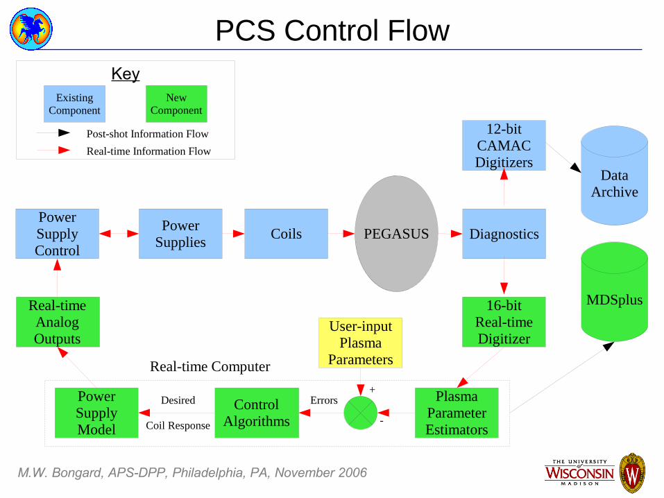
PCS Control Flow
PEGASUS
PlasmaParameterEstimators
Diagnostics
16-bitReal-timeDigitizer
12-bitCAMACDigitizers
DataArchive
MDSplus
PowerSupplies
PowerSupplyControl
Coils
User-inputPlasma
Parameters
Errors+
-Control
Algorithms
PowerSupplyModel
Real-timeAnalogOutputs
Desired
Coil Response
Real-time Computer
Key
Post-shot Information Flow
Real-time Information Flow
ExistingComponent
NewComponent
M.W. Bongard, APS-DPP, Philadelphia, PA, November 2006
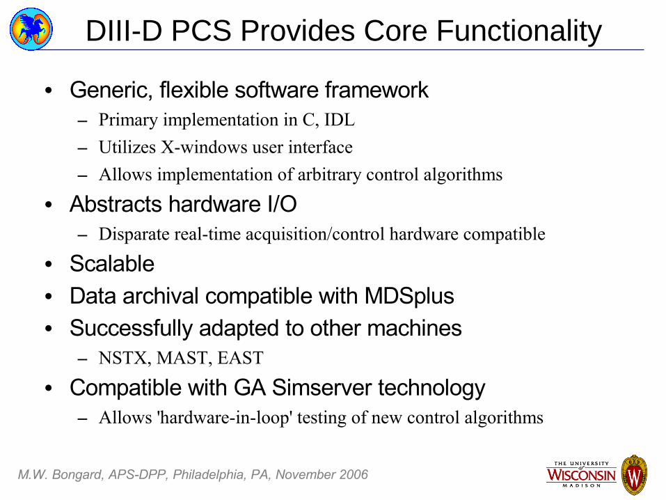
DIII-D PCS Provides Core Functionality
• Generic, flexible software framework– Primary implementation in C, IDL– Utilizes X-windows user interface– Allows implementation of arbitrary control algorithms
• Abstracts hardware I/O– Disparate real-time acquisition/control hardware compatible
• Scalable• Data archival compatible with MDSplus• Successfully adapted to other machines
– NSTX, MAST, EAST
• Compatible with GA Simserver technology– Allows 'hardware-in-loop' testing of new control algorithms

M.W. Bongard, APS-DPP, Philadelphia, PA, November 2006
Extensive Magnetic Diagnostics Available
• Pegasus has full magnetics set– 26 Flux loops– 6 Wall loops– 43 Poloidal Mirnov coil array– LFS, HFS Toroidal Mirnov array– Rogowski coils– Diamagnetic loops
• Raw signals digitized– Software integration for I
p, Φ, B
– PCS requires hardware integration
• Subset initially used for control

M.W. Bongard, APS-DPP, Philadelphia, PA, November 2006
EF Coil Sets are Primary Actuators
• 12 Independent Coil Sets Available– 8 EF, 2 Divertor, OH, TF
• Sets typically coupled for B control– 2-3 coil sets in series per group– Connections provided via patch panel
• Coil current control utilized– 5 coil groups capable of independent
operation• 3 EF, TF, OH
– Provides operator control without unwieldy machine operation space
– Current ratings dependent on power supply configuration
Pegasus poloidal coil system (to scale).A typical configuration of EF123,45,678
is shown.

M.W. Bongard, APS-DPP, Philadelphia, PA, November 2006
Flexible Waveform Control Possible
• Coil-current control obtained via switching power supplies in H-bridge configuration– IGBT: 900V EF, TF– IGCT: 2700V OH– See Battaglia, et. al., VP1.000008 this
session
• Strictly proportional analog PWM control– OH: A-D hybrid controller– TF, EF: analog controller
• Operators must exploit knowledge of system dynamics to obtain desired response
20kA
15
10
5
0
TF
50x10 -3403020100Shot Time (s)
-20kA
-10
0
10
20
OH
10kA86420
EF1
23
8000A
6000
4000
2000
0
EF6
78
-1500A
-1000
-500
0
EF4
5
35750 Demand Achieved
M.W. Bongard, APS-DPP, Philadelphia, PA, November 2006
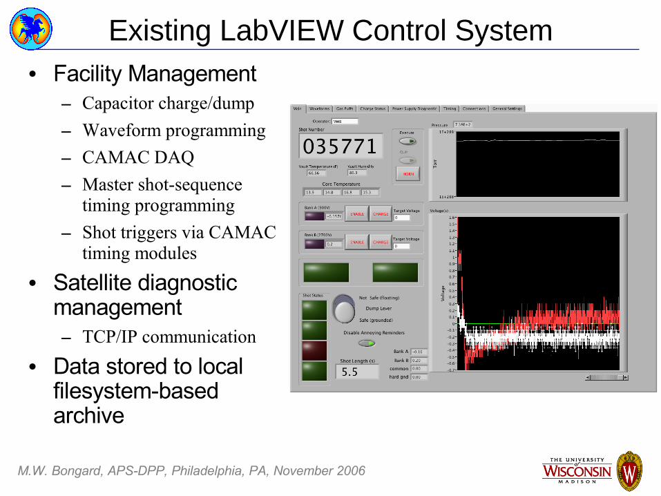
Existing LabVIEW Control System• Facility Management
– Capacitor charge/dump– Waveform programming– CAMAC DAQ– Master shot-sequence
timing programming– Shot triggers via CAMAC
timing modules
• Satellite diagnostic management– TCP/IP communication
• Data stored to local filesystem-based archive

M.W. Bongard, APS-DPP, Philadelphia, PA, November 2006
PCS Real-time DAQ/Control Hardware• D-TACQ ACQ196CPCI
– 500 kHz sampling rate– 96 Channels AI, 16-bit,
simultaneously sampled– 16 Channels AO, 16-bit– 32 Channels DIO, TTL– Embedded Linux OS– Low-latency mode enables
direct control by host CPU
• StarFabric Bus Extender– 64-bit, 66 MHz link to host– Digitizer addressed as PCI
card in host computer
M.W. Bongard, APS-DPP, Philadelphia, PA, November 2006
PCS Computer Systems
• Control Computer– Dual AMD Opteron 250 Processors, 1GB RAM– Red Hat Linux OS– Runs non-realtime PCS management servers– Archives shot programming– Can be used for off-line modeling, simulations
• Real-time Host– Dual Intel Xeon Processors, 1 GB RAM– Modified Linux 2.4.20 kernel– CPCI digitizer logical extension of PCI bus– Performs in-shot sampling and analysis– Writes analog control signal demands– Archives data acquired in-shot

M.W. Bongard, APS-DPP, Philadelphia, PA, November 2006
GA Integrated Modeling Suite
• Matlab tools for modeling of:– Vacuum Vessel/Coil systems– Magnetic probes– Plasma response
• Machine-independent– DIII-D, NSTX, EAST, KSTAR, ITER modeled
• Extensively validated on DIII-D• Provides framework for additional advanced tools
– Simserver
M.W. Bongard, APS-DPP, Philadelphia, PA, November 2006
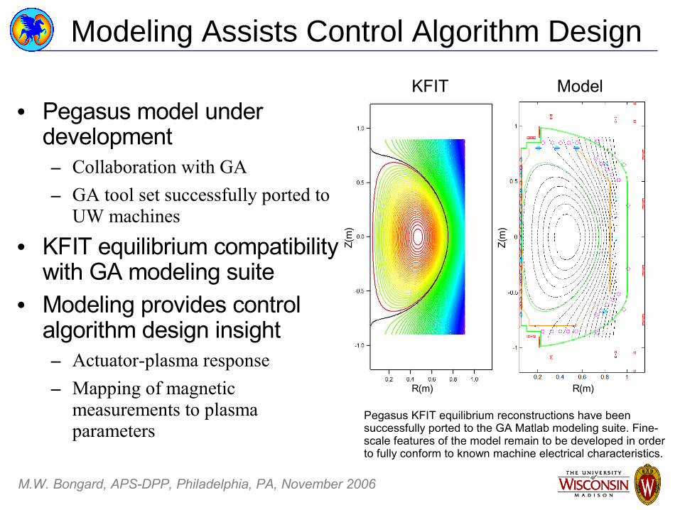
Modeling Assists Control Algorithm Design
• Pegasus model under development– Collaboration with GA– GA tool set successfully ported to
UW machines
• KFIT equilibrium compatibility with GA modeling suite
• Modeling provides control algorithm design insight– Actuator-plasma response– Mapping of magnetic
measurements to plasma parameters
R(m) R(m)
Z(m
)
Z(m
)
Pegasus KFIT equilibrium reconstructions have been successfully ported to the GA Matlab modeling suite. Fine-scale features of the model remain to be developed in order to fully conform to known machine electrical characteristics.
KFIT Model

M.W. Bongard, APS-DPP, Philadelphia, PA, November 2006
Initial Pegasus Simserver Constructed
• Stub Simserver built at GA• Simulink model coupling:
– VV/Plasma response model– Power supply models– PCS interaction
• Capable of ANSI C export– Hardware-in-loop simulation
• Realistic models under development– IGBT, IGCT modeling– PWM behavior– Engineering constraints
• Validation of Pegasus Simserver needed

M.W. Bongard, APS-DPP, Philadelphia, PA, November 2006
PCS Integration Fronts at Pegasus
• Significant development required for routine PCS use• Analog signal processing electronics
– Hardware magnetics integration required
• MDSplus Deployment– LabVIEW, Igor Pro compatibility layer developed
• Control Algorithm Development– Initially replicate existing waveform generation (P demand)– Add integral, derivative feedback for improved response– R, Z, I
p control
• Control Code Integration– Enables proper shot-sequence PCS command integration
M.W. Bongard, APS-DPP, Philadelphia, PA, November 2006
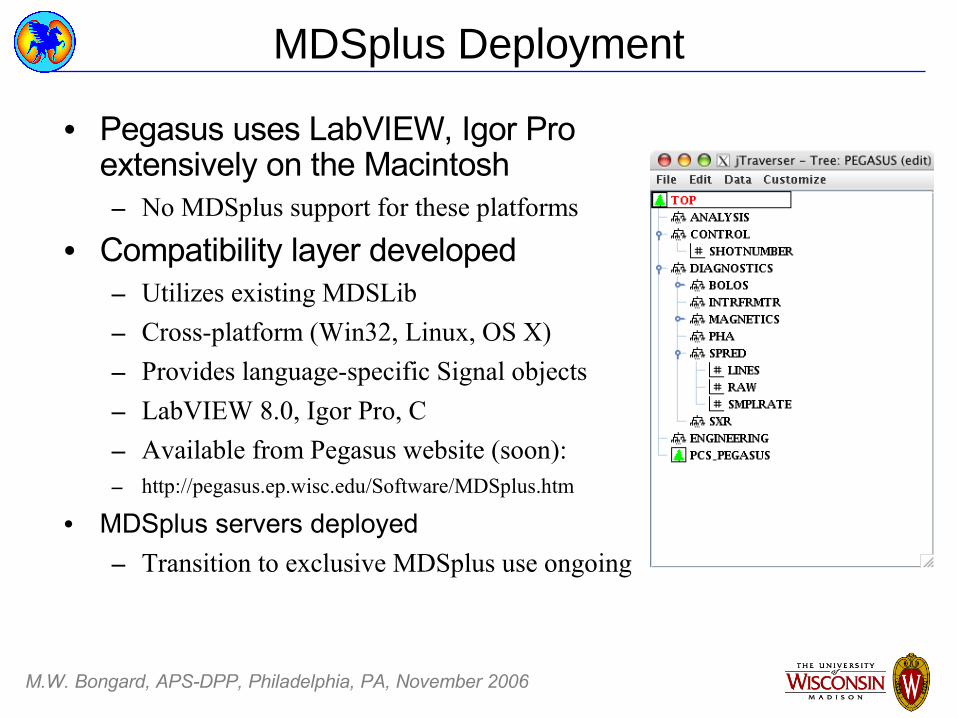
MDSplus Deployment
• Pegasus uses LabVIEW, Igor Pro extensively on the Macintosh– No MDSplus support for these platforms
• Compatibility layer developed– Utilizes existing MDSLib– Cross-platform (Win32, Linux, OS X)– Provides language-specific Signal objects– LabVIEW 8.0, Igor Pro, C– Available from Pegasus website (soon):– http://pegasus.ep.wisc.edu/Software/MDSplus.htm
• MDSplus servers deployed– Transition to exclusive MDSplus use ongoing

M.W. Bongard, APS-DPP, Philadelphia, PA, November 2006
Control Code Integration
• PCS adapted to shot cycle– Pure LabVIEW interface
emulates internal PCS TCP/IP messages
– Control code manages PCS state transitions
– PCS triggered via external CAMAC TSM system
• MDSplus integration via mdscwrap library
• Successfully deployed August 2006
Waveserver Msgserver
Lockserver
XIDL User Interface
RealtimeProcess
ControlCode
Schematic of TCP/IP links in the Pegasus PCS deployment
M.W. Bongard, APS-DPP, Philadelphia, PA, November 2006
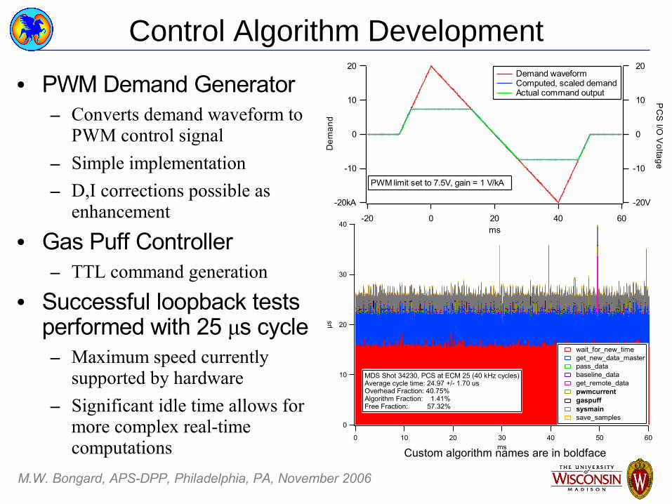
Control Algorithm Development
• PWM Demand Generator– Converts demand waveform to
PWM control signal– Simple implementation– D,I corrections possible as
enhancement
• Gas Puff Controller– TTL command generation
• Successful loopback tests performed with 25 μs cycle – Maximum speed currently
supported by hardware– Significant idle time allows for
more complex real-time computations
40
30
20
10
0
µs
6050403020100ms
wait_for_new_time get_new_data_master pass_data baseline_data get_remote_data pwmcurrent gaspuff sysmain save_samples
MDS Shot 34230, PCS at ECM 25 (40 kHz cycles)Average cycle time: 24.97 +/- 1.70 usOverhead Fraction: 40.75%Algorithm Fraction: 1.41%Free Fraction: 57.32%
-20kA
-10
0
10
20
Dem
and
6040200-20ms
-20V
-10
0
10
20
PC
S I/O
Voltage
Demand waveform Computed, scaled demand Actual command output
PWM limit set to 7.5V, gain = 1 V/kA
Custom algorithm names are in boldface

M.W. Bongard, APS-DPP, Philadelphia, PA, November 2006
Summary
• GA PCS Framework and Modeling Tools Deployed– PCS hardware, software in-place and operational– Modeling development ongoing collaboration
• Integration of PCS to existing structure complete
• Cross-platform MDSplus interfaces developed– LabVIEW 8.0, Igor Pro, C
• First tests of R, Z, Ip controlled operations with PCS
due in 2007
M.W. Bongard, APS-DPP, Philadelphia, PA, November 2006
Acknowledgments
General AtomicsDave HumphreysRobert Johnson
Ben PenaflorMike Walker
D-TACQ Solutions, LtdPeter Milne
The author would like to thank the following individuals fortheir helpful advice, code, and support:

M.W. Bongard, APS-DPP, Philadelphia, PA, November 2006
Reprints