implementation of seakeeping in ship manoeuvring simulator
TRANSCRIPT
www.fl andershydraulicsresearch.be
17_013_4FHR reports
Implementation of seakeeping in ship manoeuvring simulator
NetCDF as a new exchange fi le format between hydrodynamic models and the ship simulator
Implementation of seakeeping in ship manoeuvring simulator
NetCDF as a new exchange file format between hydrodynamic models and the ship simulator
Donatini, L.; Verwilligen, J.; Vanlede, J.; Mostaert, F.
F-WL-PP2.1.3-2 Version 1 Valid as from 1/09/2017
Cover figure © The Government of Flanders, Department of Mobility and Public Works, Flanders Hydraulics Research
Legal notice
Flanders Hydraulics Research is of the opinion that the information and positions in this report are substantiated by the available data and knowledge at the time of writing. The positions taken in this report are those of Flanders Hydraulics Research and do not reflect necessarily the opinion of the Government of Flanders or any of its institutions. Flanders Hydraulics Research nor any person or company acting on behalf of Flanders Hydraulics Research is responsible for any loss or damage arising from the use of the information in this report.
Copyright and citation
© The Government of Flanders, Department of Mobility and Public Works, Flanders Hydraulics Research 2020 D/2020/3241/306
This publication should be cited as follows:
Donatini, L.; Verwilligen, J.; Vanlede, J.; Mostaert, F. (2020). Implementation of seakeeping in ship manoeuvring simulator: NetCDF as a new exchange file format between hydrodynamic models and the ship simulator. Version 3.0. FHR Reports, 17_013_4. Flanders Hydraulics Research: Antwerp
Reproduction of and reference to this publication is authorised provided the source is acknowledged correctly.
Document identification
Customer: Flanders Hydraulics Research Ref.: WL2020R17_013_4 Keywords (3-5): netCDF, exchange files, simulator, hydrodynamic models Knowledge domains: Harbours and waterways > Manoeuvring behaviour > Currents > Simulations Text (p.): 28 Appendices (p.): / Confidentiality: No Available online Author(s): Donatini, L.
Control
Name Signature
Reviser(s): Vanlede, J
Project leader: Verwilligen, J.
Approval
Head of Division: Mostaert, F.
Reden:Ik keur dit document goed
Getekend door:Joris Vanlede (Signature)Getekend op:2021-02-16 12:25:04 +01:0
Reden:Ik keur dit document goed
Getekend door:Jeroen Verwilligen (SignatGetekend op:2021-02-09 14:32:10 +01:0
Reden:Ik keur dit document goed
Getekend door:Frank Mostaert (SignatureGetekend op:2021-02-09 14:55:17 +01:0
Implementation of seakeeping in ship manoeuvring simulator - NetCDF as a new exchange file format between hydrodynamic models and the ship simulator
Final version WL2020R17_013_4 III
Abstract
This report describes a possible use of netCDF files as a new exchange format between the hydrodynamic models and the ship manoeuvring simulator. The netCDF format has many advantages with respect to the currently used ASCII files, and allows to easily manage complex environmental data (e.g. time dependent 3D fields).

F-WL-PP2.1.3-2 Version 1 Valid as from 1/09/2017
Implementation of seakeeping in ship manoeuvring simulator - NetCDF as a new exchange file format between hydrodynamic models and the ship simulator
Final version WL2020R17_013_4 V
Contents
Abstract ............................................................................................................................................................ III
Contents ............................................................................................................................................................ V
List of figures ................................................................................................................................................... VII
1 Introduction ............................................................................................................................................... 1
2 The ASCII files format ................................................................................................................................ 2
2.1 Structure ............................................................................................................................................ 2
2.2 Further processing ............................................................................................................................. 2
2.2.1 Simulator requirements............................................................................................................. 2
2.2.2 Spatial interpolation .................................................................................................................. 3
2.2.3 Vector components ................................................................................................................... 3
2.3 SCALDIS 3D model for River Scheldt .................................................................................................. 4
2.4 Shortcomings of present ASCII format .............................................................................................. 4
2.4.1 Number of files .......................................................................................................................... 4
2.4.2 Repetition of data ...................................................................................................................... 4
2.4.3 Size of files ................................................................................................................................. 4
2.4.4 Extension to 3D meshes ............................................................................................................ 4
2.4.5 More variables ........................................................................................................................... 4
2.4.6 Data access ................................................................................................................................ 5
2.4.7 Connectivity data ....................................................................................................................... 5
2.4.8 Speed-direction ......................................................................................................................... 5
3 NetCDF ....................................................................................................................................................... 6
3.1 File format description ...................................................................................................................... 6
3.1.1 Header ....................................................................................................................................... 6
3.1.2 Dimensions ................................................................................................................................ 6
3.1.3 Variables .................................................................................................................................... 6
3.1.4 Attributes ................................................................................................................................... 7
3.1.5 Global attributes ........................................................................................................................ 7
3.1.6 Groups ....................................................................................................................................... 7
3.1.7 Conventions ............................................................................................................................... 7
3.2 CF conventions .................................................................................................................................. 7
3.2.1 Global attributes ........................................................................................................................ 8
3.2.2 Variable attributes ..................................................................................................................... 8
Implementation of seakeeping in ship manoeuvring simulator - NetCDF as a new exchange file format between hydrodynamic models and the ship simulator
VI WL2020R17_013_4 Final version
3.2.3 Coordinate variables .................................................................................................................. 8
3.2.4 Coordinate reference system .................................................................................................... 9
3.3 UGRID conventions .......................................................................................................................... 10
3.3.1 Topology .................................................................................................................................. 10
3.3.2 2D triangular mesh .................................................................................................................. 10
3.3.3 Extension to hybrid meshes .................................................................................................... 12
3.3.4 3D layered mesh ...................................................................................................................... 12
3.3.5 Data on unstructured meshes ................................................................................................. 12
3.3.6 Multiple meshes ...................................................................................................................... 13
3.4 SGRID conventions .......................................................................................................................... 13
3.4.1 Topology .................................................................................................................................. 13
3.4.2 Dimensions .............................................................................................................................. 13
3.4.3 Padding .................................................................................................................................... 14
3.4.4 2D grid ..................................................................................................................................... 14
3.4.5 Vertical dimensions ................................................................................................................. 16
3.4.6 Data on grids ............................................................................................................................ 16
3.5 Performance of netCDF ................................................................................................................... 17
4 Template of netCDF exchange file - UGRID ............................................................................................. 18
4.1 Dimensions ...................................................................................................................................... 18
4.2 Global attributes .............................................................................................................................. 18
4.3 Mesh variables ................................................................................................................................. 18
4.3.1 Horizontal coordinate system ................................................................................................. 19
4.3.2 Bounding box ........................................................................................................................... 19
4.3.3 Vertical coordinate system ...................................................................................................... 19
4.4 Time variables .................................................................................................................................. 20
4.5 Physical data variables ..................................................................................................................... 20
4.5.1 Bathymetry .............................................................................................................................. 21
4.5.2 Sea surface height ................................................................................................................... 21
4.5.3 Water density .......................................................................................................................... 21
4.5.4 Current velocity ....................................................................................................................... 21
5 Template of netCDF exchange file – SGRID ............................................................................................. 24
5.1 Dimensions ...................................................................................................................................... 24
5.2 Global attributes .............................................................................................................................. 24
5.3 Mesh variables ................................................................................................................................. 24
5.4 Time variables .................................................................................................................................. 25
5.5 Physical data variables ..................................................................................................................... 25
6 References ............................................................................................................................................... 28
Implementation of seakeeping in ship manoeuvring simulator - NetCDF as a new exchange file format between hydrodynamic models and the ship simulator
Final version WL2020R17_013_4 VII
List of figures
Figure 1 – Structure of an ASCII file produced by the Mod2ShipSim toolbox. .................................................. 3
Figure 2 – Header of a sample netCDF file, basic_file.nc, printed through the utility ncdump. ....................... 6
Figure 3 – Example of a grid mapping variable according to the CF standard.................................................. 9
Figure 4 – Graphical representation of a simple triangular mesh. .................................................................. 10
Figure 5 – Header of a sample netCDF file containing the topology information for a 2D triangular mesh according to the UGRID conventions. ............................................................................................................. 11
Figure 6 – Data variable mapped on a 3D layered mesh. The dimensions follow C ordering (time is the slowest varying one). ....................................................................................................................................... 13
Figure 7 – Padding types according to the SGRID conventions. Taken from (7). ............................................ 14
Figure 8 – Header of a sample netCDF file containing the topology information for a 2D staggered grid according to the SGRID conventions. .............................................................................................................. 15
Figure 9 – Example of an Arakawa D staggered grid. ...................................................................................... 16
Figure 10 – Data variables mapped on different edges of a 3D layered staggered grid. The location of the two components of the current velocity follow the Arakawa C convention for staggered grids. .................. 17
Figure 11 – Header of the UGRID template exchange netCDF file. Part 1: dimensions, mesh variables and time variables. ................................................................................................................................................. 22
Figure 12 – Header of the UGRID template exchange netCDF file. Part 2: physical data variables and global attributes. ........................................................................................................................................................ 23
Figure 13 – Header of the SGRID template exchange netCDF file. Part 1: dimensions, mesh variables and time variables. ................................................................................................................................................. 26
Figure 14 – Header of the SGRID template exchange netCDF file. Part 2: physical data variables and global attributes. ........................................................................................................................................................ 27

Implementation of seakeeping in ship manoeuvring simulator - NetCDF as a new exchange file format between hydrodynamic models and the ship simulator
Final version WL2020R17_013_4 1
1 Introduction
The ship manoeuvring simulator can currently take as input only time independent 2D current fields. The tidal water level is even more limited: only one level can be defined in each simulation, thus assuming a spatial and temporal independent tide. The aim of project 17_013 is to improve the environment description in the simulator, starting with the possibility to deal with 3D, time dependent current fields and time and space dependent tidal water levels.
Concerning currents, the input to the simulator is provided by numerical hydrodynamic models run by WatSed. The output of the hydrodynamic models is post-processed by WatSed into intermediate files which are provided to Nautica. These files, which will be referred as exchange files from now on, are further processed by Nautica to obtain the input files needed by the simulator.
Due to the above mentioned limitations in the simulator environment description, only 2D current fields are presently provided to Nautica. The current fields are exchanged in the form of ASCII files, each containing a 2D current field relative to a specific time frame.
A first step towards the improvement of the environment description in the simulator is to get more data from the hydrodynamic models. An increase in the amount of exchanged data cannot be easily accommodated with the ASCII files currently in use: therefore, a possible change in the exchange file format is investigated.
In this report, netCDF is proposed as a convenient format for exchange files. The netCDF format is widely used in meteorology and oceanography to deal with very large amounts of data. Moreover, it is a format already known to WatSed, and for which a complete MATLAB library is available, making it suitable to be seamlessly integrated in the actual pre-processing toolboxes used by Nautica. Almost all the presently available hydrodynamic models use either triangular meshes or staggered structured grids, with the optional third dimension managed through a layered approach. In this document the focus is therefore put only on these two types of spatial discretization.
Once an increased amount of environmental data is exchanged, the problem of making such data readable by the simulator still remains. Due to the availability of C and Fortran libraries, an interface to read netCDF files could be added in the simulator tooling domain to make such files importable.
Implementation of seakeeping in ship manoeuvring simulator - NetCDF as a new exchange file format between hydrodynamic models and the ship simulator
Final version WL2020R17_013_4 2
2 The ASCII files format
2.1 Structure
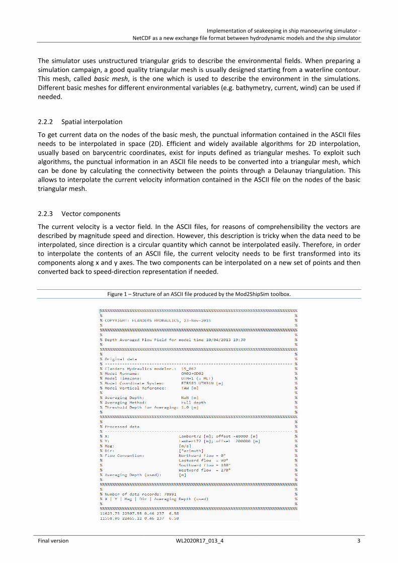
At the moment, the current fields resulting from numerical calculations performed by WatSed are provided to the Nautica group in the form of ASCII files. For tidal environments the output is typically associated with a spring and a neap tidal cycle, while for channels output is generated for different discharge volumes. The ASCII files are obtained from the hydrodynamic models raw outputs by means of Mod2ShipSim (1), a MATLAB toolbox developed by WatSed. Each of the ASCII files contains a 2D current field defined on an array of points. The file is valid for one specific time instant along one of the two tidal cycles.
The structure of the ASCII files is the following:
• The first 42 lines contain a header with some metadata about the file. Among such metadata: o Day of production o Simulation time o Description of the data o Coordinates and reference levels o Number of records
• The following lines contain the actual data. Each line is relative to a point and contains the following fields, separated by spaces:
o X coordinate of the point o Y coordinate of the point o Current speed o Current direction o Averaging depth
Next to the ASCII ouput of the 2D flow fields, an excel file is generated that contains the information on tides during the simulation, typically in the form of a timeseries of water levels at one or more reference stations in the zone of interest.
An example of an ASCII file produced by the Mod2ShipSim toolbox is given in Figure 1.
Typical algorithmic steps performed by mod2shipsim are:
• Velocities at points below a threshold minimum water depth (e.g. 1m) are filtered out • Calculation of depth averaged velocities based on 3D model results. This step is not done when the
input is a 2D model. Apart from regular depth averaging, there is also the option for a force-equivalent method of depth averaging. Typically depth averaging is done over the draft depth of a ship.
• Coordinate conversion between the horizontal coordinate systems used in the model and the simulator
• Velocities are converted from (U, V) to (dir, mag)
2.2 Further processing
2.2.1 Simulator requirements
The simulator can presently deal with 2D time independent current fields. Therefore, only the information contained in one ASCII file can be used during a simulation. In order to make the current field contained in an ASCII file available as a compatible input, additional processing is required.
Implementation of seakeeping in ship manoeuvring simulator - NetCDF as a new exchange file format between hydrodynamic models and the ship simulator
Final version WL2020R17_013_4 3
The simulator uses unstructured triangular grids to describe the environmental fields. When preparing a simulation campaign, a good quality triangular mesh is usually designed starting from a waterline contour. This mesh, called basic mesh, is the one which is used to describe the environment in the simulations. Different basic meshes for different environmental variables (e.g. bathymetry, current, wind) can be used if needed.
2.2.2 Spatial interpolation
To get current data on the nodes of the basic mesh, the punctual information contained in the ASCII files needs to be interpolated in space (2D). Efficient and widely available algorithms for 2D interpolation, usually based on barycentric coordinates, exist for inputs defined as triangular meshes. To exploit such algorithms, the punctual information in an ASCII file needs to be converted into a triangular mesh, which can be done by calculating the connectivity between the points through a Delaunay triangulation. This allows to interpolate the current velocity information contained in the ASCII file on the nodes of the basic triangular mesh.
2.2.3 Vector components
The current velocity is a vector field. In the ASCII files, for reasons of comprehensibility the vectors are described by magnitude speed and direction. However, this description is tricky when the data need to be interpolated, since direction is a circular quantity which cannot be interpolated easily. Therefore, in order to interpolate the contents of an ASCII file, the current velocity needs to be first transformed into its components along x and y axes. The two components can be interpolated on a new set of points and then converted back to speed-direction representation if needed.
Figure 1 – Structure of an ASCII file produced by the Mod2ShipSim toolbox.
Implementation of seakeeping in ship manoeuvring simulator - NetCDF as a new exchange file format between hydrodynamic models and the ship simulator
Final version WL2020R17_013_4 4
2.3 SCALDIS 3D model for River Scheldt
Recently, a new hydrodynamic model for the River Scheldt was developed by WatSed. The new model, called SCALDIS (2), is based on the Telemac software and uses a 3D layered unstructured mesh, i.e. a 2D triangular mesh with prismatic vertical layers. A complete validation (3) of the model shows good performances with respect to measured data, outlining the possibility for the unstructured grid modelling approach to supersede the previous approach based on structured grids and nested domains.
To provide current data to the simulator, the 3D current fields simulated by the SCALDIS model are actually converted into 2D fields by means of depth averaging techniques. Moreover, the topology information of the triangular grid used by Telemac is simply discarded in the production of the ASCII exchange files, and a new triangulation needs to be carried out if the data are to be interpolated on a different grid (see 2.2.2).
2.4 Shortcomings of present ASCII format
2.4.1 Number of files
Only one time frame is contained per ASCII file, so the number of files needed to describe a complete tidal cycle can be large. For example, with the conventional time-step of 10 minutes, 79 files are needed for each tidal cycle (13 hours). A large number of input files can be confusing for the user and increases the probability of banal errors like inadvertent deletion of some of the files or selection of the wrong file to be processed.
2.4.2 Repetition of data
Assuming the description of a tidal cycle in multiple ASCII files, the x and y coordinates are repeated along the files. This approach allows each file to be treated independently, but at the same time it introduces redundant information, increasing the total size of the files. While this could be a limited issue for 2D grids, an extension to 3D grids would worsen the problem.
2.4.3 Size of files
ASCII files are very simple to read and modify, but are not as “size effective” as other binary formats, independently from the repeated information issue described above. The same information stored in binary format can occupy considerably lower volumes on disk. Again, this may not be a problem for limited size 2D grids, but it can become so when dealing with large 3D meshes.
2.4.4 Extension to 3D meshes
All the problems described in the previous points become worse if an extension to 3D layered meshes is foreseen. By keeping the present structure of the files, the number of files and the size of redundant information would increase linearly with the number of 3D layers to be considered. In order to reduce the number of files and/or the total size, the data of different layers could be merged in the same file, at the price however of an increased complexity of the files.
2.4.5 More variables
The same considerations of the point above hold if more output variables from the hydrodynamic models (e.g. water density and tidal water level) are sought for.
Implementation of seakeeping in ship manoeuvring simulator - NetCDF as a new exchange file format between hydrodynamic models and the ship simulator
Final version WL2020R17_013_4 5
2.4.6 Data access
Data stored in ASCII files can be easily accessed and modified. While this can be an asset in some circumstances, e.g. when the need of “quick and dirty” modifications arises, it also increases the risk of inadvertent modifications, which could result in errors very hard to track back.
2.4.7 Connectivity data
As outlined in 2.3, even when the connectivity data between the points is available from the hydrodynamic model, such information is discarded in the ASCII files to keep them simple. When that information is available, it would be useful to have it exchanged as well. If not, a new triangulation of the points in the ASCII file needs to be performed. This requires additional computational time and can produce different results from the original triangulation, where several constraints on the mesh edges could have been taken into account (e.g. grid boundaries and internal islands).
2.4.8 Speed-direction
The present ASCII files describe the current velocity by means of speed and direction. As discussed in 2.2.3, this is not convenient for interpolation. Therefore, a description of the current velocity by components in an orthonormal reference system should be preferred.
Implementation of seakeeping in ship manoeuvring simulator - NetCDF as a new exchange file format between hydrodynamic models and the ship simulator
Final version WL2020R17_013_4 6
3 NetCDF
3.1 File format description
NetCDF is a binary format which can be used to conveniently store array-oriented data. In the netCDF format, variables are stored as named n-dimensional arrays. All the metadata needed to describe the dataset or the single variables are stored as named attributes in the same file, making it self-describing.
According to the official website (4): “netCDF (network Common Data Form) is a set of interfaces for array-oriented data access and a distributed collection of data access libraries for C, Fortran, C++, Java, and other languages. The netCDF libraries support a machine-independent format for representing scientific data”.
In order to better describe the netCDF format, a few key elements need to be introduced.
3.1.1 Header
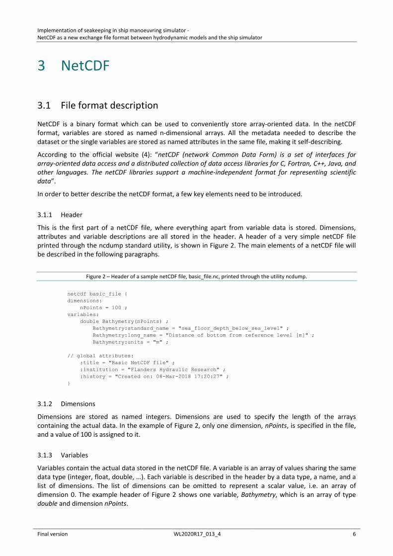
This is the first part of a netCDF file, where everything apart from variable data is stored. Dimensions, attributes and variable descriptions are all stored in the header. A header of a very simple netCDF file printed through the ncdump standard utility, is shown in Figure 2. The main elements of a netCDF file will be described in the following paragraphs.
Figure 2 – Header of a sample netCDF file, basic_file.nc, printed through the utility ncdump.
netcdf basic_file { dimensions: nPoints = 100 ; variables: double Bathymetry(nPoints) ; Bathymetry:standard_name = "sea_floor_depth_below_sea_level" ; Bathymetry:long_name = "Distance of bottom from reference level [m]" ; Bathymetry:units = "m" ; // global attributes: :title = "Basic NetCDF file" ; :institution = "Flanders Hydraulic Research" ; :history = "Created on: 08-Mar-2018 17:20:27" ; }
3.1.2 Dimensions
Dimensions are stored as named integers. Dimensions are used to specify the length of the arrays containing the actual data. In the example of Figure 2, only one dimension, nPoints, is specified in the file, and a value of 100 is assigned to it.
3.1.3 Variables
Variables contain the actual data stored in the netCDF file. A variable is an array of values sharing the same data type (integer, float, double, …). Each variable is described in the header by a data type, a name, and a list of dimensions. The list of dimensions can be omitted to represent a scalar value, i.e. an array of dimension 0. The example header of Figure 2 shows one variable, Bathymetry, which is an array of type double and dimension nPoints.
Implementation of seakeeping in ship manoeuvring simulator - NetCDF as a new exchange file format between hydrodynamic models and the ship simulator
Final version WL2020R17_013_4 7
3.1.4 Attributes
Attributes store the metadata associated with a variable. Attributes have a name, a value (usually a string but integers and floats are possible) and a variable to which they are associated. In the example of Figure 2, the three attributes standard_name, long_name and units (see 3.2.2) are associated with the Bathymetry variable.
3.1.5 Global attributes
Global attributes store metadata associated with the entire file. In the example of Figure 2 three global attributes are shown, namely title, institution and history, which contain metadata describing the collection of variables (the netCDF file itself) rather than the single variables in it.
3.1.6 Groups
Groups are internal hierarchical subdivisions of a netCDF file, which can be thought as directories in a file system. The only role of groups is to better organize the content of a netCDF file. A netCDF can have an arbitrary number of groups, including none. In the example of Figure 2, no groups are defined. A netCDF file can be thought as a group itself, often referred to as the root group. If further groups are defined, they are considered to be all children of the root group.
An important aspect of groups concerns dimensions. Dimensions are specified at a group level, and are scoped to be visible inside the group itself and all children groups. Therefore, a dimension defined in the root group, at file level, is visible in all the other groups. On the other hand, a dimension specified in a group is not visible in its parent or sibling groups.
3.1.7 Conventions
The netCDF format gives ample freedom in defining the structure of data. The names and contents of groups, dimensions, variables and attributes can be chosen freely. This freedom is an advantage for the user, but can complicate data exchange and generic software development. In order to overcome these issues, several sets of conventions were developed.
The most widely used conventions for environmental data are the Climate and Forecast (CF) conventions (5). These conventions were developed for meteorological applications and are now recognized as a recommended standard for netCDF files. The CF conventions only deal with regular grids. More recently, a new set of conventions, UGRID (6), was developed to extend the CF conventions to unstructured grids. On the top of this standard an additional set of conventions was developed aimed at a convenient management of staggered data on structured grids: the SGRID conventions (7). The UGRID and SGRID conventions are particularly relevant in the field of hydrodynamic modelling since triangular meshes and staggered structured grids cover almost all the possible output formats from hydrodynamic models. A brief overview of the three sets of conventions is given below.
3.2 CF conventions
The following is just a brief overview of some relevant aspects of the CF conventions. A reference is made to (5) for a much more complete description.
The CF standard specifies “metadata that provide a definitive description of what the data in each variable represents, and of the spatial and temporal properties of the data” (5). Only attribute names and values are standardized, leaving complete freedom in the choice of names for dimensions and variables. The standard outlines some conventional attributes (either mandatory or optional) but allows a file to contain also as many non-standard attributes as required, provided that such non-standard attributes do not replace the standard ones.

Implementation of seakeeping in ship manoeuvring simulator - NetCDF as a new exchange file format between hydrodynamic models and the ship simulator
Final version WL2020R17_013_4 8
3.2.1 Global attributes
The CF conventions define the following conventional global attributes:
• title • institution • source (e.g. model with which the data were produced) • history (record of modifications to the original data, including file creation) • references (published references about the data) • comment • Conventions (netCDF conventions followed, e.g. “CF-1.7”)
None of these global attributes is mandatory, and other non-standard global attributes can be introduced as desired.
3.2.2 Variable attributes
Three variable attributes are standardized in the CF conventions:
• standard_name • long_name • units (mandatory)
The standard_name attribute is used to allow an unmistakable description of the physical quantity. The standard_name attribute should contain a conventional name for the variable, selected from a predefined table (8). The long_name attribute is used to specify a more descriptive name for the variable, which value is not standardized. The units attribute describe the measuring unit and is mandatory for dimensional quantities.
3.2.3 Coordinate variables
The CF standard outlines some conventions for coordinate variables, which are variables used to locate data in space and time. Four coordinates are standardized:
• latitude • longitude • vertical • time
Latitude and longitude are selected as the reference coordinate variables to locate data on the earth surface due to their internationally recognized standard. According to the CF standard latitude and longitude variables should always be present, eventually along with additional variables describing the location of data in other reference systems (e.g. projections).
More freedom is given in the selection of the reference vertical coordinate variable, which could be dimensional or dimensionless. The vertical coordinate variable requires the additional positive attribute, which can have the values of “up” and “down” to specify the direction of positive values. A dimensionless vertical coordinate variable usually have also a formula_terms and a computed_standard_name attributes. The first attribute specifies which variables in the file can be used as the terms to calculate a dimensional coordinate starting from the dimensionless one, while the second one gives a standard name to univocally identify the dimensional coordinate calculated through the formula. Different formulas are specified in the conventions for different types of dimensionless vertical coordinates. The interested reader is referred to the CF conventions (5), appendix D for more details.
The time coordinate needs to be expressed as a certain amount of seconds/minutes/hours/days elapsed from a reference date and time, taking time zone into consideration. The unit attribute of the time coordinate variable should contain a string formatted like:
“seconds since 1992-10-8 15:15:42.5 -6:00”
Implementation of seakeeping in ship manoeuvring simulator - NetCDF as a new exchange file format between hydrodynamic models and the ship simulator
Final version WL2020R17_013_4 9
where the unit is specified (seconds/minutes/…), followed by the reference date and time and by the time zone with respect to UTC. An additional attribute calendar needs to be specified as well to make clear how a new date should be calculated starting from the reference one.
The CF standard additionally requires that “Any of a variable’s dimensions that is an independently varying latitude, longitude, vertical, or time dimension and that has a size greater than one must have a corresponding coordinate variable, i.e., a one-dimensional variable with the same name as the dimension”.
3.2.4 Coordinate reference system
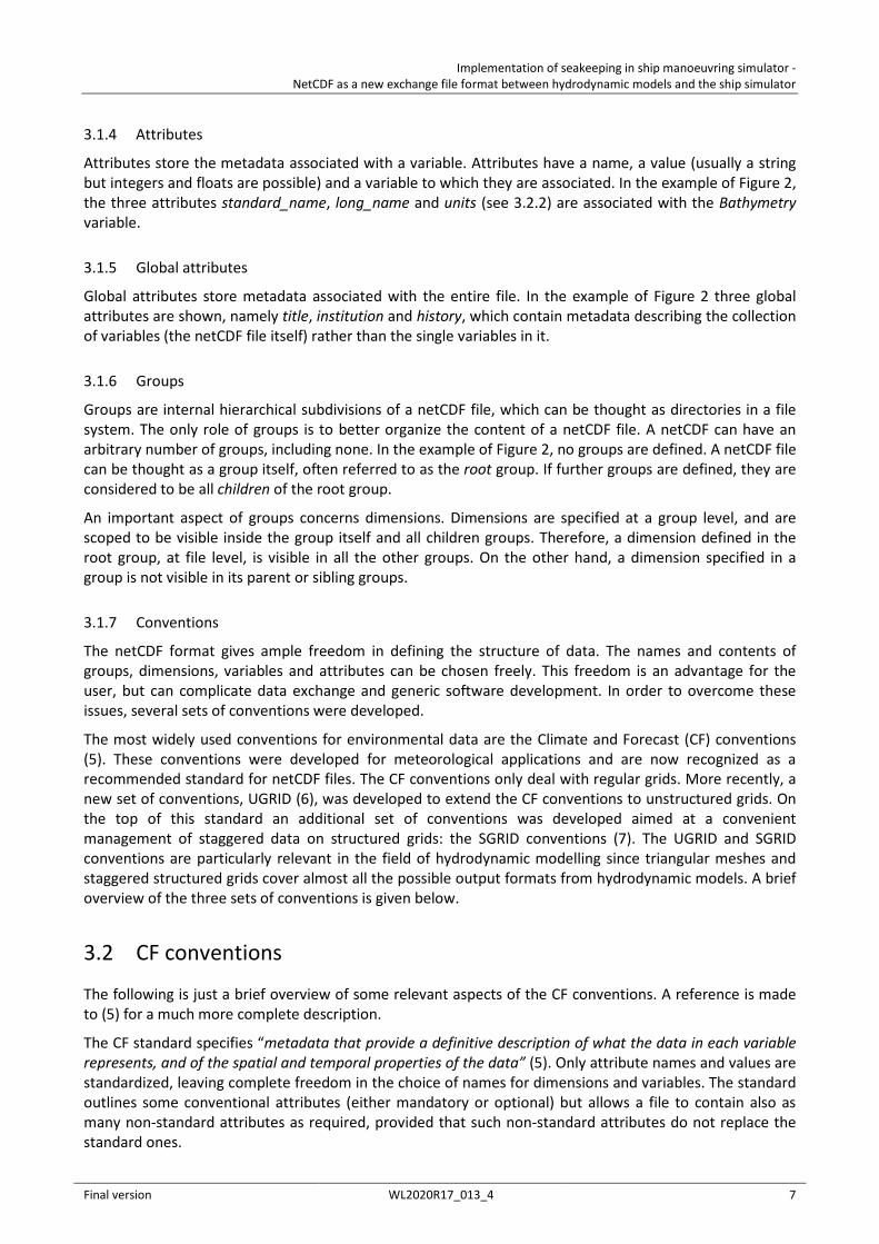
If the horizontal coordinates used in the file are not latitude and longitude, the CF standard recommends the definition of the coordinate reference system through a dummy variable, referred to as the grid mapping variable, which contains all the needed information in the form of attributes. A rigid format is enforced for the attributes defining the coordinate system. First of all, a mandatory attribute grid_mapping_name needs to be defined. This attribute describes the reference system through a string which can be selected among a limited number of options. Depending on the type of reference system specified through the grid_mapping_name attribute, different additional attributes can be specified to define the details of the reference system (e.g. semi_major_axis and inverse_flattening for a transverse_mercator projection). This format is quite cumbersome and lacks some flexibility, since projections different from the few ones specified in the standard could not be defined.
In order to associate data variables with the correct coordinate reference system, the variable attribute grid_mapping is used. This attribute contains the name of the grid mapping variable which stores all the reference system information. An example, taken from the CF standard, is presented in Figure 3, where a Lambert projection is specified through the dummy variable Lambert_Conformal. The data variable Temperature is associated with the geographical reference system through the grid_mapping attribute. Note the additional presence of latitude and longitude variables.
Figure 3 – Example of a grid mapping variable according to the CF standard.
dimensions: y = 228; x = 306; time = 41; variables: int Lambert_Conformal; Lambert_Conformal:grid_mapping_name = "lambert_conformal_conic"; Lambert_Conformal:standard_parallel = 25.0; Lambert_Conformal:longitude_of_central_meridian = 265.0; Lambert_Conformal:latitude_of_projection_origin = 25.0; double y(y); y:units = "km"; y:long_name = "y coordinate of projection"; y:standard_name = "projection_y_coordinate"; double x(x); x:units = "km"; x:long_name = "x coordinate of projection"; x:standard_name = "projection_x_coordinate"; double lat(y, x); lat:units = "degrees_north"; lat:long_name = "latitude coordinate"; lat:standard_name = "latitude"; double lon(y, x); lon:units = "degrees_east"; lon:long_name = "longitude coordinate"; lon:standard_name = "longitude"; int time(time); time:long_name = "forecast time"; time:units = "hours since 2004-06-23T22:00:00Z"; float Temperature(time, y, x); Temperature:units = "K"; Temperature:long_name = "Temperature @ surface"; Temperature:missing_value = 9999.0;
Implementation of seakeeping in ship manoeuvring simulator - NetCDF as a new exchange file format between hydrodynamic models and the ship simulator
Final version WL2020R17_013_4 10
Temperature:coordinates = "lat lon"; Temperature:grid_mapping = "Lambert_Conformal";
3.3 UGRID conventions
Quoting the manual for the UGRID conventions “In its most basic form unstructured data may be stored as data defined at a series of points, the CF-conventions are then sufficient. However, it is often useful or even necessary to also know the topology of the underlying unstructured mesh” (6).
The UGRID standard specify a set of conventions to store the topological information of an unstructured mesh in netCDF files. The UGRID conventions covers the cases of 1D network, 2D mesh (triangular or mixed), 3D layered mesh (2D mesh with vertical layers), and fully unstructured 3D mesh. The focus below will be put on 2D triangular and 3D layered meshes since these are the types of meshes used in both the hydrodynamic models and the simulator.
3.3.1 Topology
The mesh topology is defined as “interconnection of various geometrical elements of the mesh” (6). Four types of mesh elements are defined in the UGRID standard:
• node : a point identified by two or three coordinates. • edge : a line connecting two nodes. • face : a surface enclosed by a set of edges. • volume : volume enclosed by a set of faces.
The topology information is stored as attributes of a dummy variable. Some of those attributes contain the name of auxiliary variables where the actual topology data are stored (e.g. the coordinates of the nodes). A complete explanation, with an example, is given below.
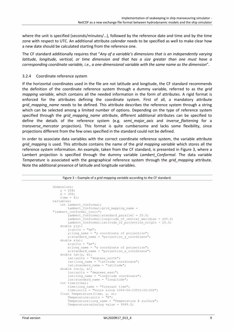
3.3.2 2D triangular mesh
The header of a sample netCDF file containing a 2D triangular mesh is given in Figure 5.
First of all, the number of nodes and faces in the unstructured mesh are specified as dimensions. In the example, the triangular mesh is composed of 4 points (nodes) and 2 triangles (faces), as set by the dimensions nMesh1_nodes and nMesh1_faces. A third dimension, nMesh1_face_nodes, specifies the number of nodes associated to each face. In the case of 2D triangular meshes this dimension has a value of 3. An graphical representation of the simple triangular mesh described in the sample netCDF file, with four nodes and two faces, is given in Figure 4.
Figure 4 – Graphical representation of a simple triangular mesh.
Implementation of seakeeping in ship manoeuvring simulator - NetCDF as a new exchange file format between hydrodynamic models and the ship simulator
Final version WL2020R17_013_4 11
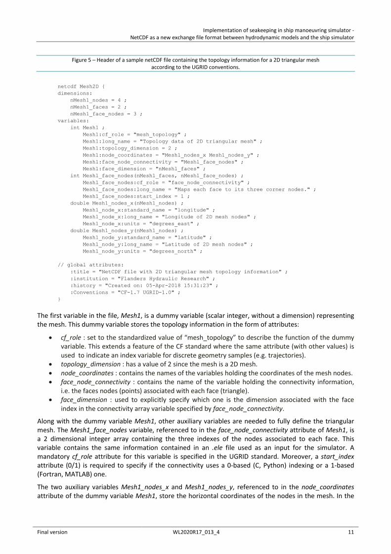
Figure 5 – Header of a sample netCDF file containing the topology information for a 2D triangular mesh according to the UGRID conventions.
netcdf Mesh2D { dimensions: nMesh1_nodes = 4 ; nMesh1_faces = 2 ; nMesh1_face_nodes = 3 ; variables: int Mesh1 ; Mesh1:cf_role = "mesh_topology" ; Mesh1:long_name = "Topology data of 2D triangular mesh" ; Mesh1:topology_dimension = 2 ; Mesh1:node_coordinates = "Mesh1_nodes_x Mesh1_nodes_y" ; Mesh1:face_node_connectivity = "Mesh1_face_nodes" ; Mesh1:face_dimension = "nMesh1_faces" ; int Mesh1_face_nodes(nMesh1_faces, nMesh1_face_nodes) ; Mesh1_face_nodes:cf_role = "face_node_connectivity" ; Mesh1_face_nodes:long_name = "Maps each face to its three corner nodes." ; Mesh1_face_nodes:start_index = 1 ; double Mesh1_nodes_x(nMesh1_nodes) ; Mesh1_node_x:standard_name = "longitude" ; Mesh1_node_x:long_name = "Longitude of 2D mesh nodes" ; Mesh1_node_x:units = "degrees_east" ; double Mesh1_nodes_y(nMesh1_nodes) ; Mesh1_node_y:standard_name = "latitude" ; Mesh1_node_y:long_name = "Latitude of 2D mesh nodes" ; Mesh1_node_y:units = "degrees_north" ; // global attributes: :title = "NetCDF file with 2D triangular mesh topology information" ; :institution = "Flanders Hydraulic Research" ; :history = "Created on: 05-Apr-2018 15:31:23" ; :Conventions = "CF-1.7 UGRID-1.0" ; }
The first variable in the file, Mesh1, is a dummy variable (scalar integer, without a dimension) representing the mesh. This dummy variable stores the topology information in the form of attributes:
• cf_role : set to the standardized value of “mesh_topology” to describe the function of the dummy variable. This extends a feature of the CF standard where the same attribute (with other values) is used to indicate an index variable for discrete geometry samples (e.g. trajectories).
• topology_dimension : has a value of 2 since the mesh is a 2D mesh. • node_coordinates : contains the names of the variables holding the coordinates of the mesh nodes. • face_node_connectivity : contains the name of the variable holding the connectivity information,
i.e. the faces nodes (points) associated with each face (triangle). • face_dimension : used to explicitly specify which one is the dimension associated with the face
index in the connectivity array variable specified by face_node_connectivity.
Along with the dummy variable Mesh1, other auxiliary variables are needed to fully define the triangular mesh. The Mesh1_face_nodes variable, referenced to in the face_node_connectivity attribute of Mesh1, is a 2 dimensional integer array containing the three indexes of the nodes associated to each face. This variable contains the same information contained in an .ele file used as an input for the simulator. A mandatory cf_role attribute for this variable is specified in the UGRID standard. Moreover, a start_index attribute (0/1) is required to specify if the connectivity uses a 0-based (C, Python) indexing or a 1-based (Fortran, MATLAB) one.
The two auxiliary variables Mesh1_nodes_x and Mesh1_nodes_y, referenced to in the node_coordinates attribute of the dummy variable Mesh1, store the horizontal coordinates of the nodes in the mesh. In the
Implementation of seakeeping in ship manoeuvring simulator - NetCDF as a new exchange file format between hydrodynamic models and the ship simulator
Final version WL2020R17_013_4 12
case of the example in Figure 5, the coordinates are expressed as latitude and longitude, according to the CF standards (see 3.2.3).
The UGRID standard specifies additional optional conventions to describe many other topological features of unstructured meshes. For example, the edges converging to each node or surrounding each face can be stored in additional auxiliary variables, as well the neighboring faces associated to each face. These topological details, which could be needed by advanced applications (e.g. walking algorithms for point location in triangulations) are not shown here to keep the examples simple and similar to the needed application.
3.3.3 Extension to hybrid meshes
The previous structure, valid for triangular meshes, can be easily extended to hybrid meshes composed by faces with a variable number of nodes. According to the UGRID standard this is done by replacing the dimension storing the fixed number of nodes per face (nMesh1_face_nodes dimension set to three for a triangular mesh in the previous example) with a dimension containing the maximum number of nodes per face. Moreover, a fill value attribute must be defined for the connectivity variable (e.g. face_node_connectivity:_FillValue = 99999;). This way, the faces with less nodes than the maximum number defined in the dimension will have, for all the nodes in excess, the values of the connectivity variable set to the fill value specified in the attribute.
3.3.4 3D layered mesh
The 3D layered mesh is a simple upgrade over the 2D case. A new dimension representing the number of vertical levels needs to be added, together with a variable holding the vertical coordinates of the levels, in dimensional or dimensionless form (sigma levels). As an example, which will be used in the next section, the dimension holding the number of layers could be named nMesh1_levels and the variable holding the vertical coordinates Mesh1_levels.
3.3.5 Data on unstructured meshes
The variables in the netCDF file holding the actual data can be mapped on the unstructured meshes by the introduction of two additional variable attributes:
• mesh : points to the dummy mesh topology variable of interest • location : specifies on which mesh elements the data are defined (nodes/edges/faces)
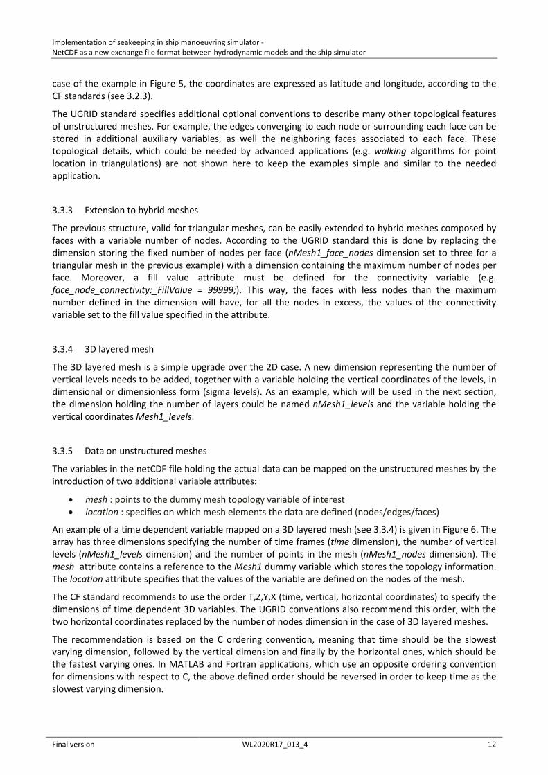
An example of a time dependent variable mapped on a 3D layered mesh (see 3.3.4) is given in Figure 6. The array has three dimensions specifying the number of time frames (time dimension), the number of vertical levels (nMesh1_levels dimension) and the number of points in the mesh (nMesh1_nodes dimension). The mesh attribute contains a reference to the Mesh1 dummy variable which stores the topology information. The location attribute specifies that the values of the variable are defined on the nodes of the mesh.
The CF standard recommends to use the order T,Z,Y,X (time, vertical, horizontal coordinates) to specify the dimensions of time dependent 3D variables. The UGRID conventions also recommend this order, with the two horizontal coordinates replaced by the number of nodes dimension in the case of 3D layered meshes.
The recommendation is based on the C ordering convention, meaning that time should be the slowest varying dimension, followed by the vertical dimension and finally by the horizontal ones, which should be the fastest varying ones. In MATLAB and Fortran applications, which use an opposite ordering convention for dimensions with respect to C, the above defined order should be reversed in order to keep time as the slowest varying dimension.
Implementation of seakeeping in ship manoeuvring simulator - NetCDF as a new exchange file format between hydrodynamic models and the ship simulator
Final version WL2020R17_013_4 13
Figure 6 – Data variable mapped on a 3D layered mesh. The dimensions follow C ordering (time is the slowest varying one).
double U(time, nMesh1_levels, nMesh1_nodes) ; U:standard_name = "sea_water_x_velocity" ; U:long_name = "3D current velocity - x component" ; U:units = "m s-1" ; U:mesh = "Mesh1" ; U:location = "node" ;
3.3.6 Multiple meshes
Following the UGRID conventions, multiple meshes can be defined in the same netCDF file. Data variables mapped to different meshes can coexist in the same file in an organized way, allowing a high degree of flexibility.
3.4 SGRID conventions
The SGRID conventions were designed as a consistent extension to the UGRID conventions aimed at the description of staggered data on structured grids. Many of the concepts introduced in the UGRID standard are kept in SGRID, like for example the idea of a dummy variable storing all the grid information in the form of attributes. In the SGRID standard, the points on a 2D grid are identified by two dimensions (along the two axes) instead of just one, while the connectivity information is not needed. The SGRID conventions introduce a convenient way to describe staggered grids based on additional dimensions and padding parameters, as explained in more detail below.
To help distinguish between the two special discretization techniques, in this document the following convention was used: the term mesh is used to indicate an unstructured grid, while the term grid is used for a structured one.
3.4.1 Topology
The definitions of grid elements (nodes, faces, edges and volumes) introduced in the UGRID conventions are used in SGRID as well. The faces, which were triangles in the case of unstructured triangular meshes, become rectangular cells. In order to assign coordinates to faces and edges, both are assumed to be represented by their geometric centers.
3.4.2 Dimensions
The points on a 2D grid (nodes) are identified by two coordinates, representing the position along two axes. Therefore, the nMesh1_nodes dimension introduced in 3.3.2, needs to be replaced by two dimensions, which we can call, for example, nGrid1_inodes and nGrid1_jnodes. A 2D variable will be a 2D array instead of a 1D array as was the case with unstructured meshes.
In order to deal with staggered data, the SGRID conventions requires additional dimensions to be present in the file. For example, two additional dimensions need to be introduced to describe variables defined on the face centers instead of on the grid nodes. As an example, these dimensions can be called nGrid1_ifaces and nGrid1_jfaces. For a variable defined on the edges of the grid, a mix between the nodes and faces dimensions can be specified to define the variable array (see Figure 10 for two examples).
A netCDF dimension holds an integer which is used to define the extent of arrays. The relationship between the values of the nodes and faces dimensions depends on something which is called padding in the SGRID conventions. A description of padding is given in the next paragraph.
Implementation of seakeeping in ship manoeuvring simulator - NetCDF as a new exchange file format between hydrodynamic models and the ship simulator
Final version WL2020R17_013_4 14
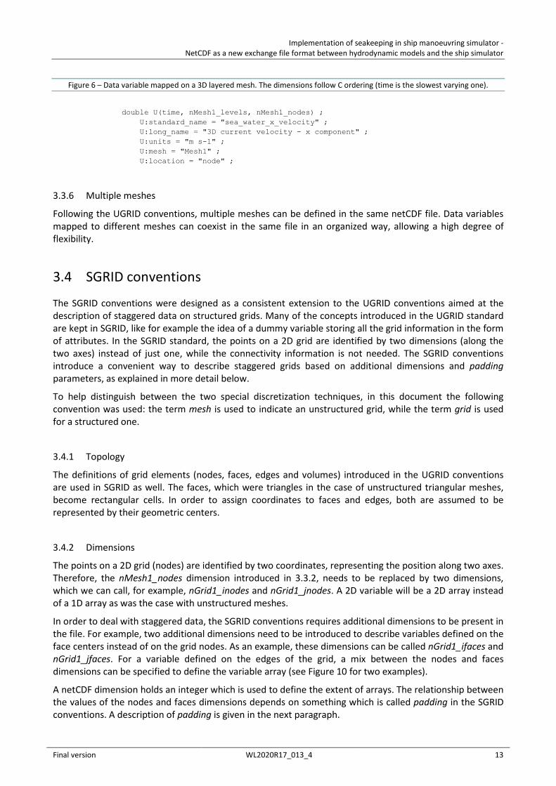
3.4.3 Padding
The concept of padding is used to specify whether an additional face is present after the last node or before the first one, in each dimension. According to the SGRID specification, “the padding type may be one of the four literal strings: ‘none’, ‘low’, ‘high’, or ‘both’ depending on whether the face_dimension is one shorter than the corresponding node_dimension (padding:none), one longer than the corresponding node_dimension (padding:both), or of equal length with one extra value stored on the low or high end of the dimension”. An example is given in Figure 7.
The relationship between the node and face dimensions is specified through an attribute of the dummy grid variable (see 3.4.4) which lists the face dimensions with the associated node dimensions and padding types in the following format:
• face_dimensions = “face_dimension1: node_dimension1 (padding: type1) face_dimension2: node_dimension2 (padding: type2)”
where:
• face_dimension1 : is the face dimension in the x direction. • node_dimension1 : is the node dimension in the x direction. • type1 : is the type of padding in the x direction, which defines the ratio between the node and face
dimensions. The padding type must be selected among the four alternatives. • the same applies for face_dimension2, node_dimension2 and type2, in the y direction.
Figure 7 – Padding types according to the SGRID conventions. Taken from (7).
3.4.4 2D grid
As in the case of UGRID conventions (see 3.3.2), a 2D grid is specified through a dummy variable, which holds all the information in the form of attributes (eventually containing the names of other variables). The attributes needed to define a staggered grid according to the SGRID conventions are:
• cf_role : set to the standardized value of “grid_topology” (see also UGRID conventions). • topology_dimension : has a value of 2 since the grid is a 2D grid. • node_dimensions : contains the name of the two node dimensions. • face_dimensions : contains the name of the two face dimensions, specifying to which node
dimensions they are related and the associated padding type (see 3.4.3). • node_coordinates : contains the names of the variables holding the coordinates of the grid nodes. • face_coordinates : contains the names of the variables holding the coordinates of the centers of
grid faces.
Implementation of seakeeping in ship manoeuvring simulator - NetCDF as a new exchange file format between hydrodynamic models and the ship simulator
Final version WL2020R17_013_4 15
Additionally, the edge dimensions and coordinates can be specified as well, but a default value can be often assumed, making this information optional. The default values specified by the SGRID standard for the edge dimensions (2D grid) are:
• edge1_dimensions = “node_dimension1 face_dimension2: node_dimension2 (padding:type2)” • edge2_dimensions = “face_dimension1: node_dimension1 (padding:type1) node_dimension2”
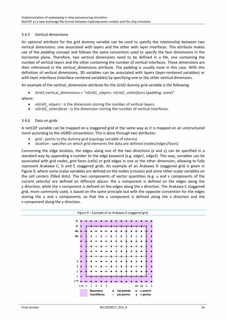
This means that the for edges oriented along the x direction, the x dimension is the same as the x dimension of faces, while the y dimension is the same as the y dimension of nodes. The opposite holds for the edges oriented along the y direction. The same considerations can be applied to edge coordinates, which can be derived from a combination of nodes and faces coordinates. According to the example in Figure 9, the v points along the x direction share the x coordinate with the cell centers and the y coordinate with the grid nodes (Arakawa D staggering).
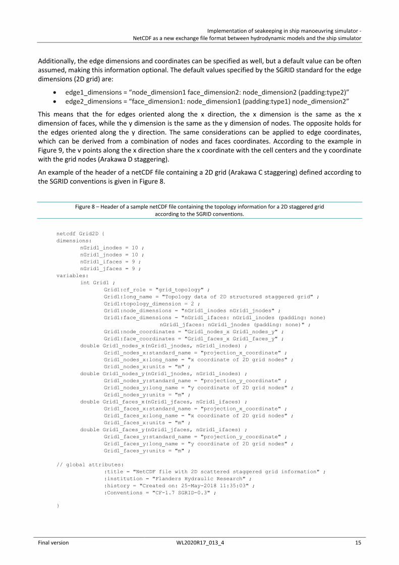
An example of the header of a netCDF file containing a 2D grid (Arakawa C staggering) defined according to the SGRID conventions is given in Figure 8.
Figure 8 – Header of a sample netCDF file containing the topology information for a 2D staggered grid according to the SGRID conventions.
netcdf Grid2D { dimensions: nGrid1_inodes = 10 ; nGrid1_jnodes = 10 ; nGrid1_ifaces = 9 ; nGrid1_jfaces = 9 ; variables: int Grid1 ; Grid1:cf_role = "grid_topology" ; Grid1:long_name = "Topology data of 2D structured staggered grid" ; Grid1:topology_dimension = 2 ; Grid1:node_dimensions = "nGrid1_inodes nGrid1_jnodes" ; Grid1:face_dimensions = "nGrid1_ifaces: nGrid1_inodes (padding: none)
nGrid1_jfaces: nGrid1_jnodes (padding: none)" ; Grid1:node_coordinates = "Grid1_nodes_x Grid1_nodes_y" ; Grid1:face_coordinates = "Grid1_faces_x Grid1_faces_y" ; double Grid1_nodes_x(nGrid1_jnodes, nGrid1_inodes) ; Grid1_nodes_x:standard_name = "projection_x_coordinate" ; Grid1_nodes_x:long_name = "x coordinate of 2D grid nodes" ; Grid1_nodes_x:units = "m" ; double Grid1_nodes_y(nGrid1_jnodes, nGrid1_inodes) ; Grid1_nodes_y:standard_name = "projection_y_coordinate" ; Grid1_nodes_y:long_name = "y coordinate of 2D grid nodes" ; Grid1_nodes_y:units = "m" ; double Grid1_faces_x(nGrid1_jfaces, nGrid1_ifaces) ; Grid1_faces_x:standard_name = "projection_x_coordinate" ; Grid1_faces_x:long_name = "x coordinate of 2D grid nodes" ; Grid1_faces_x:units = "m" ; double Grid1_faces_y(nGrid1_jfaces, nGrid1_ifaces) ; Grid1_faces_y:standard_name = "projection_y_coordinate" ; Grid1_faces_y:long_name = "y coordinate of 2D grid nodes" ; Grid1_faces_y:units = "m" ; // global attributes: :title = "NetCDF file with 2D scattered staggered grid information" ; :institution = "Flanders Hydraulic Research" ; :history = "Created on: 25-May-2018 11:35:03" ; :Conventions = "CF-1.7 SGRID-0.3" ;
}
Implementation of seakeeping in ship manoeuvring simulator - NetCDF as a new exchange file format between hydrodynamic models and the ship simulator
Final version WL2020R17_013_4 16
3.4.5 Vertical dimensions
An optional attribute for the grid dummy variable can be used to specify the relationship between two vertical dimensions: one associated with layers and the other with layer interfaces. This attribute makes use of the padding concept and follows the same convention used to specify the face dimensions in the horizontal plane. Therefore, two vertical dimensions need to be defined in a file, one containing the number of vertical layers and the other containing the number of vertical interfaces. These dimensions are then referenced in the vertical_dimensions attribute. The padding is usually none in this case. With this definition of vertical dimensions, 3D variables can be associated with layers (layer-centered variables) or with layer interfaces (interface-centered variables) by specifying one or the other vertical dimension.
An example of the vertical_dimensions attribute for the Grid1 dummy grid variable is the following:
• Grid1:vertical_dimensions = “nGrid1_vlayers: nGrid1_vinterfaces (padding: none)” where:
• nGrid1_vlayers : is the dimension storing the number of vertical layers. • nGrid1_vinterfaces : is the dimension storing the number of vertical interfaces.
3.4.6 Data on grids
A netCDF variable can be mapped on a staggered grid in the same way as it is mapped on an unstructured mesh according to the UGRID conventions. This is done through two attributes:
• grid : points to the dummy grid topology variable of interest • location : specifies on which grid elements the data are defined (nodes/edges/faces)
Concerning the edge location, the edges along one of the two directions (x and y) can be specified in a standard way by appending a number to the edge keyword (e.g. edge1, edge2). This way, variables can be associated with grid nodes, grid faces (cells) or grid edges in one or the other dimension, allowing to fully represent Arakawa C, D and E staggered grids. An example of an Arakawa D staggered grid is given in Figure 9, where some scalar variables are defined on the nodes (crosses) and some other scalar variables on the cell centers (filled dots). The two components of vector quantities (e.g. u and v components of the current velocity) are defined on different places: the u component is defined on the edges along the y direction, while the v component is defined on the edges along the x direction. The Arakawa C staggered grid, more commonly used, is based on the same principle but with the opposite convention for the edges storing the u and v components, so that the u component is defined along the x direction and the v component along the y direction.
Figure 9 – Example of an Arakawa D staggered grid.
Implementation of seakeeping in ship manoeuvring simulator - NetCDF as a new exchange file format between hydrodynamic models and the ship simulator
Final version WL2020R17_013_4 17
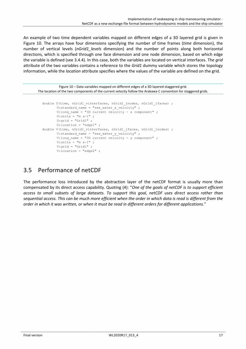
An example of two time dependent variables mapped on different edges of a 3D layered grid is given in Figure 10. The arrays have four dimensions specifying the number of time frames (time dimension), the number of vertical levels (nGrid1_levels dimension) and the number of points along both horizontal directions, which is specified through one face dimension and one node dimension, based on which edge the variable is defined (see 3.4.4). In this case, both the variables are located on vertical interfaces. The grid attribute of the two variables contains a reference to the Grid1 dummy variable which stores the topology information, while the location attribute specifies where the values of the variable are defined on the grid.
Figure 10 – Data variables mapped on different edges of a 3D layered staggered grid. The location of the two components of the current velocity follow the Arakawa C convention for staggered grids.
double U(time, nGrid1_vinterfaces, nGrid1_jnodes, nGrid1_ifaces) ; U:standard_name = "sea_water_x_velocity" ; U:long_name = "3D current velocity - x component" ; U:units = "m s-1" ; U:grid = "Grid1" ; U:location = "edge1" ; double V(time, nGrid1_vinterfaces, nGrid1_jfaces, nGrid1_inodes) ; V:standard_name = "sea_water_y_velocity" ; V:long_name = "3D current velocity - y component" ; V:units = "m s-1" ; V:grid = "Grid1" ; V:location = "edge2" ;
3.5 Performance of netCDF
The performance loss introduced by the abstraction layer of the netCDF format is usually more than compensated by its direct access capability. Quoting (4): “One of the goals of netCDF is to support efficient access to small subsets of large datasets. To support this goal, netCDF uses direct access rather than sequential access. This can be much more efficient when the order in which data is read is different from the order in which it was written, or when it must be read in different orders for different applications.”
Implementation of seakeeping in ship manoeuvring simulator - NetCDF as a new exchange file format between hydrodynamic models and the ship simulator
Final version WL2020R17_013_4 18
4 Template of netCDF exchange file - UGRID
A netCDF template for the exchange files to be received from hydrodynamic models based on unstructured grids is proposed. The template is designed based on:
• The need of additional data to improve the environment description in the simulator (3D currents, tidal water level)
• The shortcomings in the actual ASCII files (see 2.4) • The CF and UGRID conventions (see 3.2 and 3.3)
The template netCDF file contains one 3D layered unstructured mesh, defined according to the UGRID conventions, and several physical variables. The header of the UGRID template file is shown in Figure 11 and Figure 12.
4.1 Dimensions
The file dimensions in the template file are:
• nMesh1_nodes : the number of points in the triangular mesh of reference (called Mesh1) • nMesh1_faces : the number of faces in the mesh • nMesh1_face_nodes : dimension describing the number of nodes pertaining to each face • nMesh1_vlayers : the number of vertical layers • nMesh1_vinterfaces : the number of vertical interfaces • time : the number of time frames contained in the file
4.2 Global attributes
The main global attributes from the CF conventions are used. Other global attributes can be conveniently added if more metadata are needed. As an example, an attribute describing the FHR project associated with the file is added here. The global attributes defined in the template file are:
• title • institution • source • history • references • comment • Conventions • FHR_project
4.3 Mesh variables
All the mesh information is stored into the mesh variables. Only one mesh is stored in the template file, but additional meshes could be eventually added by duplicating the relevant dimensions and variables. For example, a second mesh could be added keeping the same names for dimensions and variables but using the identifier Mesh2 instead of Mesh1.
The variables used to define the mesh in the template file are:
• Mesh1 : the dummy variable mapping all the mesh information • Mesh1_face_nodes : contains the connectivity information (which nodes pertain to each face)
Implementation of seakeeping in ship manoeuvring simulator - NetCDF as a new exchange file format between hydrodynamic models and the ship simulator
Final version WL2020R17_013_4 19
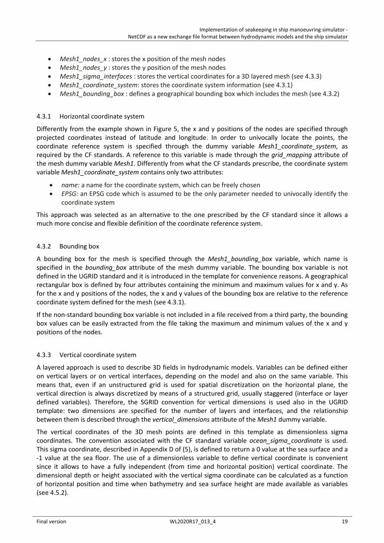
• Mesh1_nodes_x : stores the x position of the mesh nodes • Mesh1_nodes_y : stores the y position of the mesh nodes • Mesh1_sigma_interfaces : stores the vertical coordinates for a 3D layered mesh (see 4.3.3) • Mesh1_coordinate_system: stores the coordinate system information (see 4.3.1) • Mesh1_bounding_box : defines a geographical bounding box which includes the mesh (see 4.3.2)
4.3.1 Horizontal coordinate system
Differently from the example shown in Figure 5, the x and y positions of the nodes are specified through projected coordinates instead of latitude and longitude. In order to univocally locate the points, the coordinate reference system is specified through the dummy variable Mesh1_coordinate_system, as required by the CF standards. A reference to this variable is made through the grid_mapping attribute of the mesh dummy variable Mesh1. Differently from what the CF standards prescribe, the coordinate system variable Mesh1_coordinate_system contains only two attributes:
• name: a name for the coordinate system, which can be freely chosen • EPSG: an EPSG code which is assumed to be the only parameter needed to univocally identify the
coordinate system
This approach was selected as an alternative to the one prescribed by the CF standard since it allows a much more concise and flexible definition of the coordinate reference system.
4.3.2 Bounding box
A bounding box for the mesh is specified through the Mesh1_bounding_box variable, which name is specified in the bounding_box attribute of the mesh dummy variable. The bounding box variable is not defined in the UGRID standard and it is introduced in the template for convenience reasons. A geographical rectangular box is defined by four attributes containing the minimum and maximum values for x and y. As for the x and y positions of the nodes, the x and y values of the bounding box are relative to the reference coordinate system defined for the mesh (see 4.3.1).
If the non-standard bounding box variable is not included in a file received from a third party, the bounding box values can be easily extracted from the file taking the maximum and minimum values of the x and y positions of the nodes.
4.3.3 Vertical coordinate system
A layered approach is used to describe 3D fields in hydrodynamic models. Variables can be defined either on vertical layers or on vertical interfaces, depending on the model and also on the same variable. This means that, even if an unstructured grid is used for spatial discretization on the horizontal plane, the vertical direction is always discretized by means of a structured grid, usually staggered (interface or layer defined variables). Therefore, the SGRID convention for vertical dimensions is used also in the UGRID template: two dimensions are specified for the number of layers and interfaces, and the relationship between them is described through the vertical_dimensions attribute of the Mesh1 dummy variable.
The vertical coordinates of the 3D mesh points are defined in this template as dimensionless sigma coordinates. The convention associated with the CF standard variable ocean_sigma_coordinate is used. This sigma coordinate, described in Appendix D of (5), is defined to return a 0 value at the sea surface and a -1 value at the sea floor. The use of a dimensionless variable to define vertical coordinate is convenient since it allows to have a fully independent (from time and horizontal position) vertical coordinate. The dimensional depth or height associated with the vertical sigma coordinate can be calculated as a function of horizontal position and time when bathymetry and sea surface height are made available as variables (see 4.5.2).
Implementation of seakeeping in ship manoeuvring simulator - NetCDF as a new exchange file format between hydrodynamic models and the ship simulator
Final version WL2020R17_013_4 20
The sigma coordinates of vertical interfaces are specified in this template as the only vertical coordinate allowed in the exchange file, even if the hydrodynamic model outputs all its 3D variables on layer centers. This convention eliminates ambiguities on the vertical coordinates and simplifies the parsing of the file. On top of this, the sigma coordinates of the layer centers, if needed, can be trivially found by calculating the mean values of consecutive interface sigma coordinates.
4.4 Time variables
A time variable is specified in the template file according to the requirements of the CF standards. As an example, the MATLAB format for time is used (days since 0000-00-0 00:00:00), assuming a MET timezone (GMT +1). A non-standard attribute, HW_index, is added to the time variable. The aim of this attribute is to define the index along the time dimension which corresponds to the high water condition in a tidal cycle. Other times of interest can be conveniently specified in the same way. If this information is not included in a file received from a third party provider, its value can be calculated from the sea surface height at a specific point.
A value of 79 is associated with the time dimension in the template file, in agreement with the data which are currently received from the hydrodynamic models in the form of ASCII files. These data describe a tidal cycle of 13 hours with a time resolution of 10 minutes (79 timesteps).
An additional, non-standard variable is also added to the template: TimeStep. This variable holds in an attribute the value of the interval between consecutive time frames. In the template its value is set to 10 minutes (600 s), in line with the above assumption. The information contained in this variable, combined with a reference time index like the one defined above, can simplify the parsing of netCDF files, avoiding in some cases the need to perform awkward date processing tasks.
4.5 Physical data variables
The physical quantities of interest from the hydrodynamic model can be 2D or 3D fields, time-dependent or time-independent. Thanks to the netCDF format and the structure of the template file, a heterogeneous collection of variables can be stored in an organized way in the same file. The time dependency and 2D/3D characteristics of a variable can be specified through its dimensions.
All the variables can be thought as array of values defined on the points of the unstructured mesh. Therefore, all the physical variables have a dimension of nMesh1_nodes and are mapped to their mesh through the attribute mesh set to “Mesh1”. 3D variables have an additional vertical dimension (layers or interfaces) and time dependent variables have the additional dimension time. A 3D, time dependent variable has all three dimensions.
An additional, non-standard attribute was added to 3D variables to make the exchange files clearer and to facilitate parsing. The attribute vlocation indicates the location of the variable on the vertical grid, and can have the values of “layer” or “interface” respectively for variables defined on layer centers or on layer interfaces. This attribute has a similar role to that of the standard attribute location which describes the variable’s location on the horizontal mesh (for 2D or 3D layered meshes). If a file from a third party does not include such attribute, the vertical location of the variable can be deduced, with a more complex parsing process, from the variable’s dimensions and from the information contained in the attribute vertical_dimensions of the dummy mesh variable.
Implementation of seakeeping in ship manoeuvring simulator - NetCDF as a new exchange file format between hydrodynamic models and the ship simulator
Final version WL2020R17_013_4 21
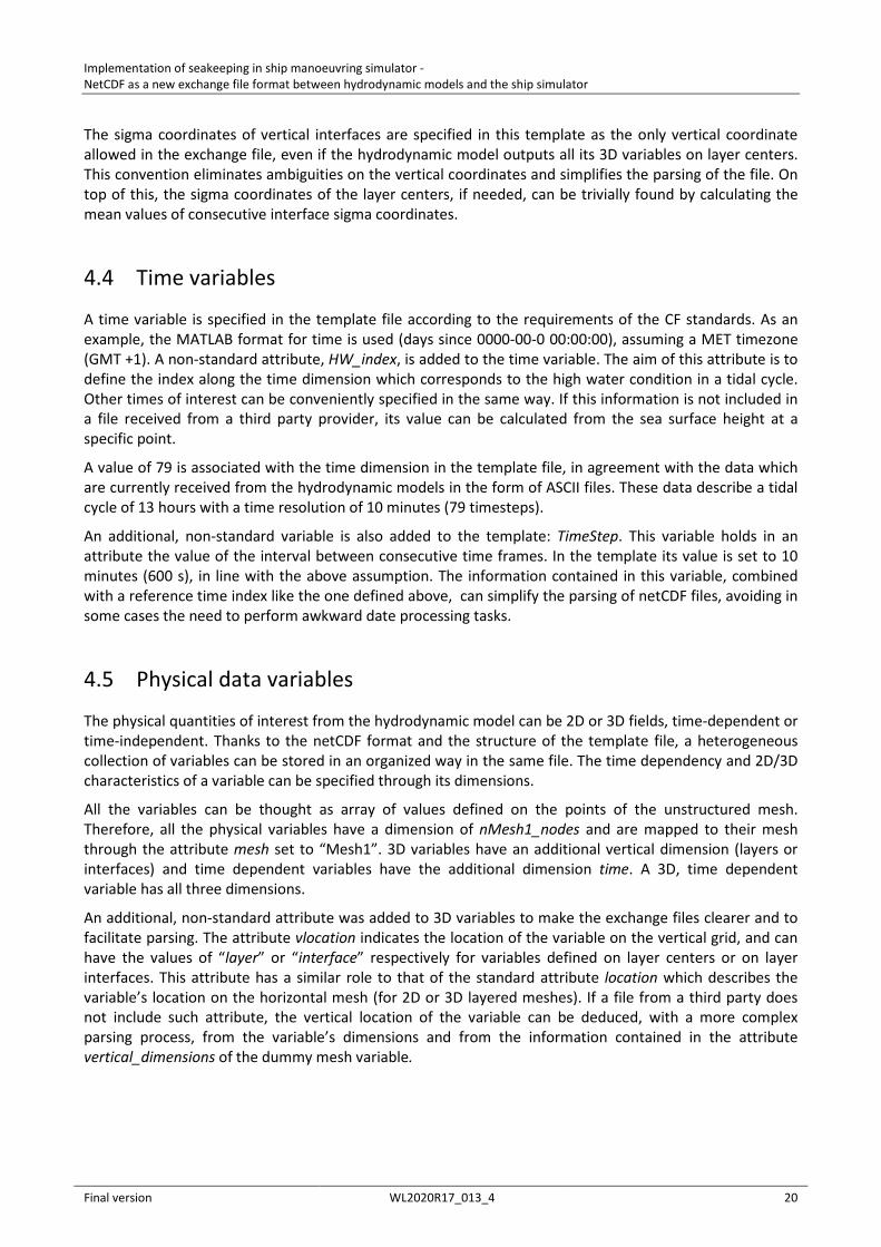
4.5.1 Bathymetry
The Bathymetry variable is defined as a 2D, time independent array, with all the attributes needed to map it on the reference mesh (see 3.3.5). This variable stores the values of the positive distance between the sea floor and the mean sea level. In order to univocally define the reference mean sea level to which the variable refers, a non-standard attribute is attached to the variable: mean_sea_level. This attribute is designed to store a string defining the reference sea level. In the template shown here, it is set to the value TAW to indicate the Tweede Algemene Waterpassing reference level.
If needed, an extension to time dependent bathymetry (e.g. sedimentological model) could be achieved by adding the time dimension to the Bathymetry variable.
4.5.2 Sea surface height
The SeaSurface variable is defined as a 2D, time dependent array. It stores the time varying values of the sea surface height above the mean sea level. The non-standard attribute mean_sea_level is added to this variable for the same reasons described in the previous paragraph.
The sea surface height, together with the sea floor depth information stored in the Bathymetry variable, are needed to translate the vertical sigma coordinates (see 4.3.3) into dimensional values of depth (positive down) or height (positive up) measured from a vertical reference level.
4.5.3 Water density
The Density variable is defined as a 3D, time dependent variable storing the water density information.
4.5.4 Current velocity
The U, V and W variables are defined as 3D, time dependent variables storing respectively the x, y and z components of the current 3D velocity.
Implementation of seakeeping in ship manoeuvring simulator - NetCDF as a new exchange file format between hydrodynamic models and the ship simulator
Final version WL2020R17_013_4 22
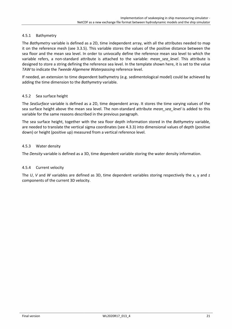
Figure 11 – Header of the UGRID template exchange netCDF file. Part 1: dimensions, mesh variables and time variables.
netcdf template_UGRID { dimensions: nMesh1_nodes = 10 ; nMesh1_faces = 8 ; nMesh1_face_nodes = 3 ; nMesh1_vinterfaces = 5 ; nMesh1_vlayers = 4 ; time = 79 ; variables: int Mesh1 ; Mesh1:cf_role = "mesh_topology" ; Mesh1:long_name = "Topology data of 2D unstructured mesh" ; Mesh1:topology_dimension = 2 ; Mesh1:node_coordinates = "Mesh1_nodes_x Mesh1_nodes_y" ; Mesh1:vertical_dimensions = "nMesh1_vlayers: nMesh1_vinterfaces (padding: none)" ; Mesh1:grid_mapping = "Mesh1_coordinate_system" ; Mesh1:face_node_connectivity = "Mesh1_face_nodes" ; Mesh1:face_dimension = "nMesh1_faces" ; Mesh1:bounding_box = "Mesh1_bounding_box" ; int Mesh1_face_nodes(nMesh1_faces, nMesh1_face_nodes) ; Mesh1_face_nodes:cf_role = "face_node_connectivity" ; Mesh1_face_nodes:long_name = "Maps each triangle (face) to its three corner nodes." ; double Mesh1_nodes_x(nMesh1_nodes) ; Mesh1_nodes_x:standard_name = "projection_x_coordinate" ; Mesh1_nodes_x:long_name = "x coordinate of 2D mesh nodes" ; Mesh1_nodes_x:units = "m" ; double Mesh1_nodes_y(nMesh1_nodes) ; Mesh1_nodes_y:standard_name = "projection_y_coordinate" ; Mesh1_nodes_y:long_name = "y coordinate of 2D mesh nodes" ; Mesh1_nodes_y:units = "m" ; double Mesh1_sigma_interfaces(nMesh1_vinterfaces) ; Mesh1_levels:standard_name = "ocean_sigma_coordinate" ; Mesh1_levels:long_name = "Ocean sigma coordinate of layer interfaces" ; Mesh1_levels:units = "sigma_level" ; Mesh1_levels:formula_terms = "sigma: Mesh1_sigma_interfaces eta: SeaSurface depth: Bathymetry" ; Mesh1_levels:computed_standard_name = "height_above_mean_sea_level" ; Mesh1_levels:vertical_scheme = "cell_centered" ; int Mesh1_coordinate_system ; Mesh1_coordinate_system:name = "Amersfoort / RD New" ; Mesh1_coordinate_system:EPSG = 28992 ; double Mesh1_bounding_box ; Mesh1_bounding_box:x_min = -92858.5 ; Mesh1_bounding_box:x_max = 109657.2 ; Mesh1_bounding_box:y_min = 333190.5 ; Mesh1_bounding_box:y_max = 428990. ; double time(time) ; time:long_name = "Time [MATLAB format]." ; time:standard_name = "time" ; time:units = "days since 0000-00-0 00:00:00 +1:00" ; time:calendar = "proleptic_gregorian" ; time:HW_index = 7 ; double TimeStep ; TimeStep:value = "600" ; TimeStep:units = "seconds" ;
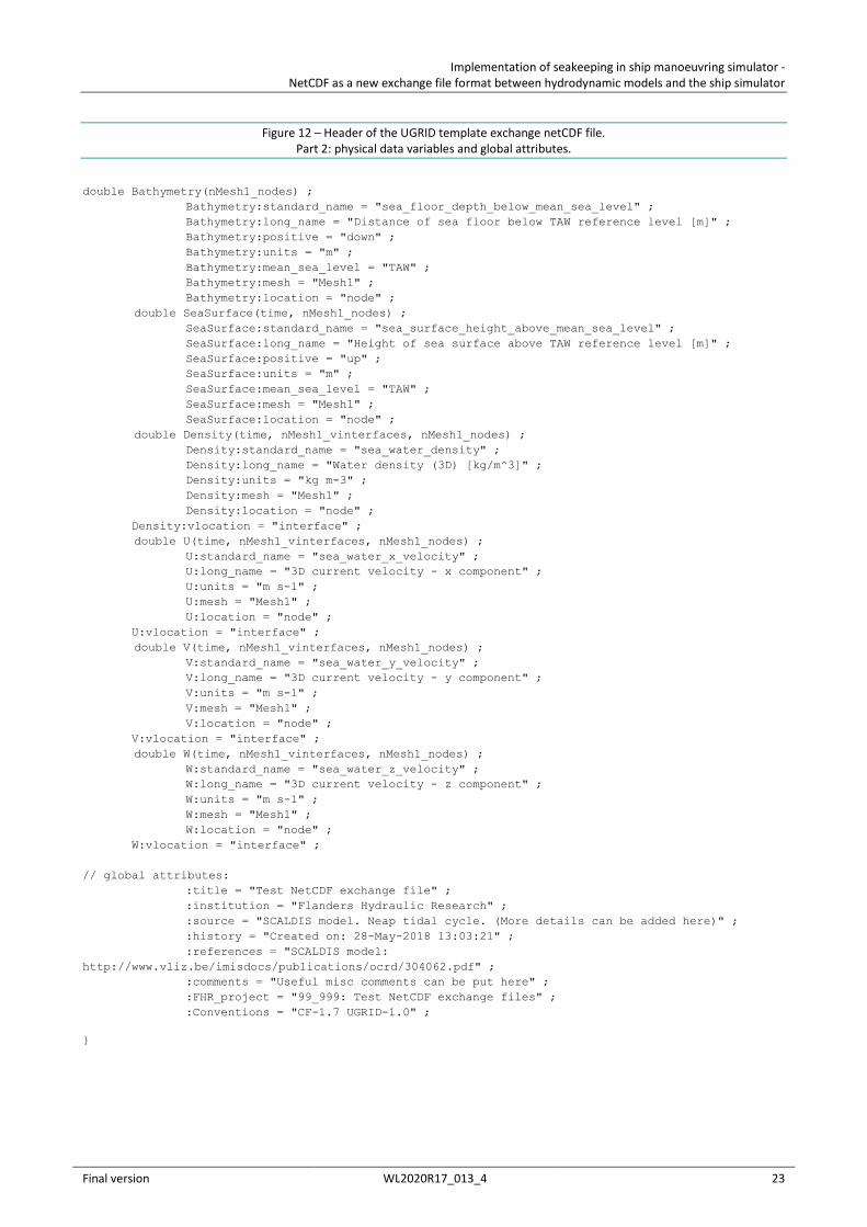
Implementation of seakeeping in ship manoeuvring simulator - NetCDF as a new exchange file format between hydrodynamic models and the ship simulator
Final version WL2020R17_013_4 23
Figure 12 – Header of the UGRID template exchange netCDF file. Part 2: physical data variables and global attributes.
double Bathymetry(nMesh1_nodes) ; Bathymetry:standard_name = "sea_floor_depth_below_mean_sea_level" ; Bathymetry:long_name = "Distance of sea floor below TAW reference level [m]" ; Bathymetry:positive = "down" ; Bathymetry:units = "m" ; Bathymetry:mean_sea_level = "TAW" ; Bathymetry:mesh = "Mesh1" ; Bathymetry:location = "node" ; double SeaSurface(time, nMesh1_nodes) ; SeaSurface:standard_name = "sea_surface_height_above_mean_sea_level" ; SeaSurface:long_name = "Height of sea surface above TAW reference level [m]" ; SeaSurface:positive = "up" ; SeaSurface:units = "m" ; SeaSurface:mean_sea_level = "TAW" ; SeaSurface:mesh = "Mesh1" ; SeaSurface:location = "node" ; double Density(time, nMesh1_vinterfaces, nMesh1_nodes) ; Density:standard_name = "sea_water_density" ; Density:long_name = "Water density (3D) [kg/m^3]" ; Density:units = "kg m-3" ; Density:mesh = "Mesh1" ; Density:location = "node" ; Density:vlocation = "interface" ; double U(time, nMesh1_vinterfaces, nMesh1_nodes) ; U:standard_name = "sea_water_x_velocity" ; U:long_name = "3D current velocity - x component" ; U:units = "m s-1" ; U:mesh = "Mesh1" ; U:location = "node" ; U:vlocation = "interface" ; double V(time, nMesh1_vinterfaces, nMesh1_nodes) ; V:standard_name = "sea_water_y_velocity" ; V:long_name = "3D current velocity - y component" ; V:units = "m s-1" ; V:mesh = "Mesh1" ; V:location = "node" ; V:vlocation = "interface" ; double W(time, nMesh1_vinterfaces, nMesh1_nodes) ; W:standard_name = "sea_water_z_velocity" ; W:long_name = "3D current velocity - z component" ; W:units = "m s-1" ; W:mesh = "Mesh1" ; W:location = "node" ; W:vlocation = "interface" ; // global attributes: :title = "Test NetCDF exchange file" ; :institution = "Flanders Hydraulic Research" ; :source = "SCALDIS model. Neap tidal cycle. (More details can be added here)" ; :history = "Created on: 28-May-2018 13:03:21" ; :references = "SCALDIS model: http://www.vliz.be/imisdocs/publications/ocrd/304062.pdf" ; :comments = "Useful misc comments can be put here" ; :FHR_project = "99_999: Test NetCDF exchange files" ; :Conventions = "CF-1.7 UGRID-1.0" ;
}
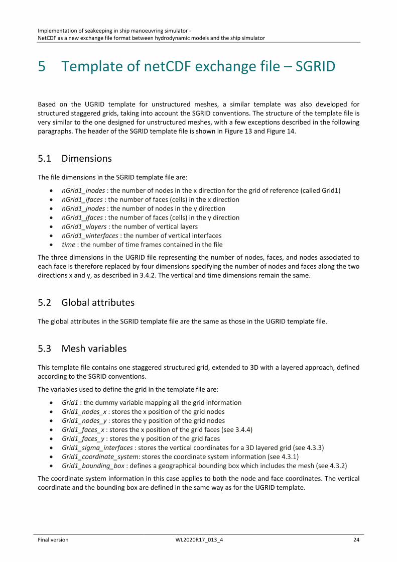
Implementation of seakeeping in ship manoeuvring simulator - NetCDF as a new exchange file format between hydrodynamic models and the ship simulator
Final version WL2020R17_013_4 24
5 Template of netCDF exchange file – SGRID
Based on the UGRID template for unstructured meshes, a similar template was also developed for structured staggered grids, taking into account the SGRID conventions. The structure of the template file is very similar to the one designed for unstructured meshes, with a few exceptions described in the following paragraphs. The header of the SGRID template file is shown in Figure 13 and Figure 14.
5.1 Dimensions
The file dimensions in the SGRID template file are:
• nGrid1_inodes : the number of nodes in the x direction for the grid of reference (called Grid1) • nGrid1_ifaces : the number of faces (cells) in the x direction • nGrid1_jnodes : the number of nodes in the y direction • nGrid1_jfaces : the number of faces (cells) in the y direction • nGrid1_vlayers : the number of vertical layers • nGrid1_vinterfaces : the number of vertical interfaces • time : the number of time frames contained in the file
The three dimensions in the UGRID file representing the number of nodes, faces, and nodes associated to each face is therefore replaced by four dimensions specifying the number of nodes and faces along the two directions x and y, as described in 3.4.2. The vertical and time dimensions remain the same.
5.2 Global attributes
The global attributes in the SGRID template file are the same as those in the UGRID template file.
5.3 Mesh variables
This template file contains one staggered structured grid, extended to 3D with a layered approach, defined according to the SGRID conventions.
The variables used to define the grid in the template file are:
• Grid1 : the dummy variable mapping all the grid information • Grid1_nodes_x : stores the x position of the grid nodes • Grid1_nodes_y : stores the y position of the grid nodes • Grid1_faces_x : stores the x position of the grid faces (see 3.4.4) • Grid1_faces_y : stores the y position of the grid faces • Grid1_sigma_interfaces : stores the vertical coordinates for a 3D layered grid (see 4.3.3) • Grid1_coordinate_system: stores the coordinate system information (see 4.3.1) • Grid1_bounding_box : defines a geographical bounding box which includes the mesh (see 4.3.2)
The coordinate system information in this case applies to both the node and face coordinates. The vertical coordinate and the bounding box are defined in the same way as for the UGRID template.
Implementation of seakeeping in ship manoeuvring simulator - NetCDF as a new exchange file format between hydrodynamic models and the ship simulator
Final version WL2020R17_013_4 25
5.4 Time variables
Time variables are defined in the same way as in the UGRID template.
5.5 Physical data variables
The physical variables contained in the template are the same ones that were included in the UGRID template (see 4.5). These variables are defined on a staggered grid according to the Arakawa C scheme, assuming that:
• Bathymetry is defined on grid faces (cell centers) • SeaSurface is defined on grid nodes • Density is defined on grid faces • U current component is defined on x oriented edges (edge1) • V current component is defined on y oriented edges (edge2) • W current component is defined on grid faces
Other staggering schemes can be easily defined in the exchange files following the SGRID conventions. In general, the original staggering scheme of the hydrodynamic model should be used in order to have the exchange data as close to the original model output as possible, making use of the flexibility provided by the SGRID standard.
Concerning the vertical dimension Density, U and V are defined on vertical interfaces, while W is defined on vertical layers. This convention is proposed here just as an example to show the possibility of defining 3D variables on different vertical grids. Again, the original conventions of the hydrodynamic models should be followed as much as possible.
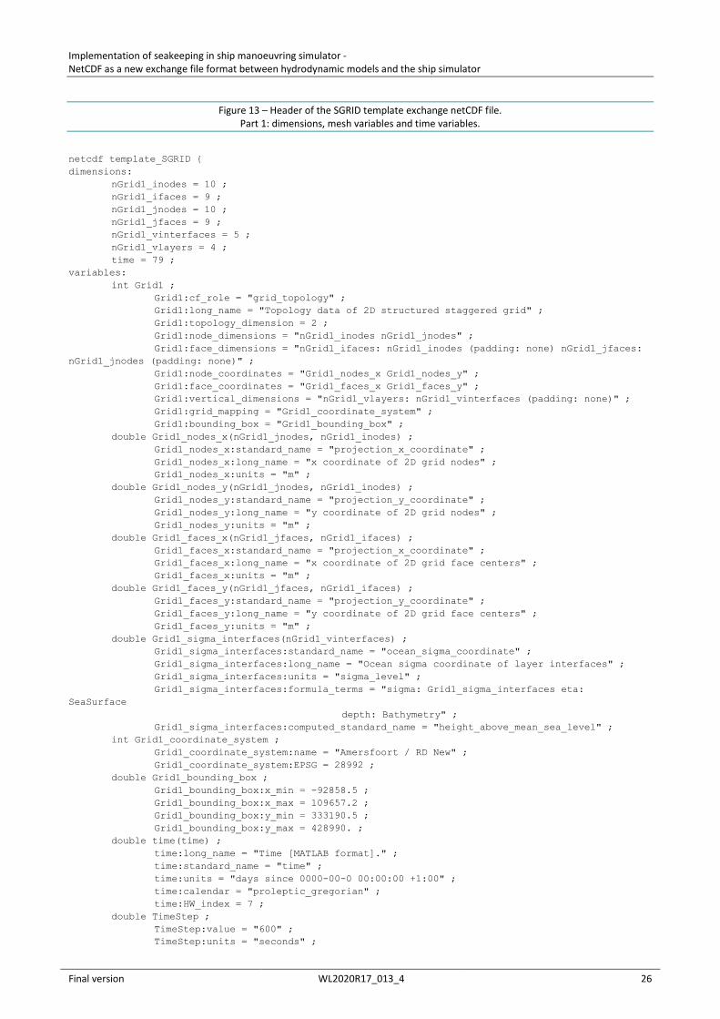
Implementation of seakeeping in ship manoeuvring simulator - NetCDF as a new exchange file format between hydrodynamic models and the ship simulator
Final version WL2020R17_013_4 26
Figure 13 – Header of the SGRID template exchange netCDF file. Part 1: dimensions, mesh variables and time variables.
netcdf template_SGRID { dimensions: nGrid1_inodes = 10 ; nGrid1_ifaces = 9 ; nGrid1_jnodes = 10 ; nGrid1_jfaces = 9 ; nGrid1_vinterfaces = 5 ; nGrid1_vlayers = 4 ; time = 79 ; variables: int Grid1 ; Grid1:cf_role = "grid_topology" ; Grid1:long_name = "Topology data of 2D structured staggered grid" ; Grid1:topology_dimension = 2 ; Grid1:node_dimensions = "nGrid1_inodes nGrid1_jnodes" ; Grid1:face_dimensions = "nGrid1_ifaces: nGrid1_inodes (padding: none) nGrid1_jfaces: nGrid1_jnodes (padding: none)" ; Grid1:node_coordinates = "Grid1_nodes_x Grid1_nodes_y" ; Grid1:face_coordinates = "Grid1_faces_x Grid1_faces_y" ; Grid1:vertical_dimensions = "nGrid1_vlayers: nGrid1_vinterfaces (padding: none)" ; Grid1:grid_mapping = "Grid1_coordinate_system" ; Grid1:bounding_box = "Grid1_bounding_box" ; double Grid1_nodes_x(nGrid1_jnodes, nGrid1_inodes) ; Grid1_nodes_x:standard_name = "projection_x_coordinate" ; Grid1_nodes_x:long_name = "x coordinate of 2D grid nodes" ; Grid1_nodes_x:units = "m" ; double Grid1_nodes_y(nGrid1_jnodes, nGrid1_inodes) ; Grid1_nodes_y:standard_name = "projection_y_coordinate" ; Grid1_nodes_y:long_name = "y coordinate of 2D grid nodes" ; Grid1_nodes_y:units = "m" ; double Grid1_faces_x(nGrid1_jfaces, nGrid1_ifaces) ; Grid1_faces_x:standard_name = "projection_x_coordinate" ; Grid1_faces_x:long_name = "x coordinate of 2D grid face centers" ; Grid1_faces_x:units = "m" ; double Grid1_faces_y(nGrid1_jfaces, nGrid1_ifaces) ; Grid1_faces_y:standard_name = "projection_y_coordinate" ; Grid1_faces_y:long_name = "y coordinate of 2D grid face centers" ; Grid1_faces_y:units = "m" ; double Grid1_sigma_interfaces(nGrid1_vinterfaces) ; Grid1_sigma_interfaces:standard_name = "ocean_sigma_coordinate" ; Grid1_sigma_interfaces:long_name = "Ocean sigma coordinate of layer interfaces" ; Grid1_sigma_interfaces:units = "sigma_level" ; Grid1_sigma_interfaces:formula_terms = "sigma: Grid1_sigma_interfaces eta: SeaSurface depth: Bathymetry" ; Grid1_sigma_interfaces:computed_standard_name = "height_above_mean_sea_level" ; int Grid1_coordinate_system ; Grid1_coordinate_system:name = "Amersfoort / RD New" ; Grid1_coordinate_system:EPSG = 28992 ; double Grid1_bounding_box ; Grid1_bounding_box:x_min = -92858.5 ; Grid1_bounding_box:x_max = 109657.2 ; Grid1_bounding_box:y_min = 333190.5 ; Grid1_bounding_box:y_max = 428990. ; double time(time) ; time:long_name = "Time [MATLAB format]." ; time:standard_name = "time" ; time:units = "days since 0000-00-0 00:00:00 +1:00" ; time:calendar = "proleptic_gregorian" ; time:HW_index = 7 ; double TimeStep ; TimeStep:value = "600" ; TimeStep:units = "seconds" ;
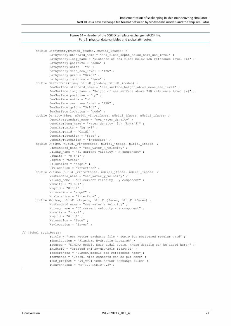
Implementation of seakeeping in ship manoeuvring simulator - NetCDF as a new exchange file format between hydrodynamic models and the ship simulator
Final version WL2020R17_013_4 27
Figure 14 – Header of the SGRID template exchange netCDF file. Part 2: physical data variables and global attributes.
double Bathymetry(nGrid1_jfaces, nGrid1_ifaces) ; Bathymetry:standard_name = "sea_floor_depth_below_mean_sea_level" ; Bathymetry:long_name = "Distance of sea floor below TAW reference level [m]" ; Bathymetry:positive = "down" ; Bathymetry:units = "m" ; Bathymetry:mean_sea_level = "TAW" ; Bathymetry:grid = "Grid1" ; Bathymetry:location = "face" ; double SeaSurface(time, nGrid1_jnodes, nGrid1_inodes) ; SeaSurface:standard_name = "sea_surface_height_above_mean_sea_level" ; SeaSurface:long_name = "Height of sea surface above TAW reference level [m]" ; SeaSurface:positive = "up" ; SeaSurface:units = "m" ; SeaSurface:mean_sea_level = "TAW" ; SeaSurface:grid = "Grid1" ; SeaSurface:location = "node" ; double Density(time, nGrid1_vinterfaces, nGrid1_jfaces, nGrid1_ifaces) ; Density:standard_name = "sea_water_density" ; Density:long_name = "Water density (3D) [kg/m^3]" ; Density:units = "kg m-3" ; Density:grid = "Grid1" ; Density:location = "face" ; Density:vlocation = "interface" ; double U(time, nGrid1_vinterfaces, nGrid1_jnodes, nGrid1_ifaces) ; U:standard_name = "sea_water_x_velocity" ; U:long_name = "3D current velocity - x component" ; U:units = "m s-1" ; U:grid = "Grid1" ; U:location = "edge1" ; U:vlocation = "interface" ; double V(time, nGrid1_vinterfaces, nGrid1_jfaces, nGrid1_inodes) ; V:standard_name = "sea_water_y_velocity" ; V:long_name = "3D current velocity - y component" ; V:units = "m s-1" ; V:grid = "Grid1" ; V:location = "edge2" ; V:vlocation = "interface" ; double W(time, nGrid1_vlayers, nGrid1_jfaces, nGrid1_ifaces) ; W:standard_name = "sea_water_z_velocity" ; W:long_name = "3D current velocity - z component" ; W:units = "m s-1" ; W:grid = "Grid1" ; W:location = "face" ; W:vlocation = "layer" ; // global attributes: :title = "Test NetCDF exchange file - SGRID for scattered regular grid" ; :institution = "Flanders Hydraulic Research" ; :source = "SIMONA model. Neap tidal cycle. (More details can be added here)" ; :history = "Created on: 29-May-2018 11:26:31" ; :references = "SIMONA model: add references here" ; :comments = "Useful misc comments can be put here" ; :FHR_project = "99_999: Test NetCDF exchange files" ; :Conventions = "CF-1.7 SGRID-0.3" ; }
Implementation of seakeeping in ship manoeuvring simulator - NetCDF as a new exchange file format between hydrodynamic models and the ship simulator
Final version WL2020R17_013_4 28
6 References
1. http://wlwiki.vlaanderen.be/wiki/pages/viewpage.action?pageId=12353891. [Online]
2. Smolders, S., et al., et al. Integraal Plan Bovenzeeschelde: Subreport 1 – SCALDIS: a 3D Hydrodynamic Model for the Scheldt Estuary. Version 5.0. WL Rapporten, 13_131. Antwerp, Belgium : Flanders Hydraulics Research, 2016.
3. WL2017R00_081_1_Update_snelheidsvelden_Zeeschelde+Sluistoegangen_Technical_Report.docx.
4. https://www.unidata.ucar.edu/software/netcdf/docs/faq.html#whatisit. [Online]
5. http://cfconventions.org/Data/cf-conventions/cf-conventions-1.7/cf-conventions.html. [Online]
6. http://ugrid-conventions.github.io/ugrid-conventions/. [Online]
7. http://sgrid.github.io/sgrid/. [Online]
8. http://cfconventions.org/Data/cf-standard-names/49/build/cf-standard-name-table.html. [Online]

DEPARTMENT MOBILITY & PUBLIC WORKSFlanders hydraulics Research
Berchemlei 115, 2140 AntwerpT +32 (0)3 224 60 35F +32 (0)3 224 60 [email protected] www.fl andershydraulicsresearch.be