implementation of power transformer differential ... · kiel uvision3 and pic simulator ide, these...
TRANSCRIPT
1
Implementation of Power Transformer Differential Protection Based on Clarke’s
Transform and Fuzzy Systems
Prasenjit Dey Prof. Priyanath Das Dr. Ajoy Kumar Chakrabothy
(P.G Scholar) (Associate Prof.) (Associate Prof.)
National Institute of Technology, Agartala, India.
Abstract
Transformer differential protection is generally
exposed to faulty operation related to abnormal
operating conditions (inrush, over excitation, etc.). This
paper presents a method for protecting and
monitoring power transformers based on fuzzy logic
and the application of Clarke’s transform. The fuzzy
logic allowed us to analyze the operating condition of
power transformers such as energization, inrush, and
over excitation. Decision making is performed by
fuzzy logic after the pre-processing of the input
signals through Clarke’s transformation. An
electrical power system was modelled using MATLAB
software to obtain the operational conditions
and fault situations needed to test the
algorithm developed. The objective of these tests
was to generate data for distinct situations for the
verification and the analysis of the proposed
methodology.
The fuzzy logic relay analyses the operating regime for
the equipment and eliminates the abnormal work
situations which generate failures. The system has been
implemented using AT89S52, PIC16F877A. These were
employed for developing the prototype relay, with all
the coding done using microcontroller C and PIC basic
languages. Kiel uVision3 and PIC Simulator IDE, these
two software been used for loading the programs on
chip. A special terminal program, developed in C
language was used to apply the current input signals to
the prototype relay in real-time by using of MAX232
serial data communication. The logic is deterministic,
computationally efficient, secure and highly reliable.
The validity of the proposed logic was exhaustively
tested by simulating various types of fault, energisation
conditions and sympathetic inrush on a 13.8 kV system
modelled in MATLAB with a 2100MVA, 13.8KV/735KV,
Star –star connected transformer. The relay was able to
correctly discriminate between inrush, internal faults
and no fault disturbances.
Keywords: Clarke’s transform, differential protection,
fuzzy system, power transformer, MATLAB, Kiel
uVision3 and PIC18 Simulator IDE.
1. Introduction
1.1 General
The function of power system protective relaying is to
initiate the prompt removal of abnormal conditions
from service of elements of power system. Since the
appearance of microprocessor in the mid-1970s, digital
protective relaying has attracted much attention [1].
The power transformer is one of the important
elements in power system. The power transformer is a
piece of electrical equipment that needs continuous
monitoring and fast protection since it is very expensive
and an essential element for a power system to perform
effectively. Power transformer internal faults may
cause extensive damage or power system instability.
Thus, different transformer protection schemes are used
to avoid interruptions of the power supply and
catastrophic losses. Electrical protective relaying of
power transformer is based on a percentage differential
International Journal of Engineering Research & Technology (IJERT)
Vol. 1 Issue 7, September - 2012ISSN: 2278-0181
1www.ijert.org

2
relaying technique [2]. This is the most common
protection technique, which provides discrimination
between an internal fault and an external fault or a
normal operating condition. Usually, differential relays
compare the currents from all terminals to a
predetermined threshold and in the case of an internal
fault; the equipment is disconnected from the power
supply as it reaches beyond the predetermined
threshold. The literature shows that the method based
on the harmonic restraint has been commonly used to
solve this problem. Harmonic-restrained differential
relay is based on the fact that magnetizing inrush
current has a large second harmonic component, and
nowadays the above technique is widely applied. But
this technique must be replaced because harmonics
occur in a normal state of power system and quantity of
second frequency component in inrush state has been
decreased because of the improvement in core steel [1]-
[6].
There are cases in which the presence of differential
currents cannot make a clear distinction between fault
and inrush. Some other operation conditions can cause
differential currents and they deserve special attention.
Some examples of these are energization, Over-
excitation. In order to prevent the relay misoperation in
these cases, it is necessary to differentiate inrush current
from fault current.
In order to improve power transformer protection,
various methods were developed for accurate and
efficient discrimination of the situations described
previously. Recently, to advance the conventional
approaches, several new AI (artificial-Intelligence)
features for protective relaying have been developed. In
1983, Phadke and Thorp proposed an algorithm based
on the flux-restraint principle to discriminate between
internal faults and other operating conditions [12]. In
1993, Wiszniewski and Kasztenny presented a fuzzy set
for power transformer differential relaying [13]. In
2003, shin et al. reported improved power transformer
protection using fuzzy logic with flux-differential
current and harmonic restraint [14]. In [7], the
differential power method was proposed to recognize
faults from inrush currents using an optimal
probabilistic neural network. Although other methods
which detect faults were shown in the literature, the
harmonic restraint has been extensively [8].
Despite progress in differential protection techniques,
faults near the end of the winding and inter-turn faults
are also a challenge for engineers and researchers since
these types of faults are difficult to protect properly
(either with the differential protection or mechanical
protection, such as the Buchholz relay) [2].
This paper presents an efficient method based on
Clarke’s transform with fuzzy sets for differential
protection of power transformers. In the proposed
technique, the input variables of the fuzzy-based relay
are differential currents resulting from Clarke’s
transform and data windowing process. The fuzzy
system is designed to distinguish internal faults from
other operating conditions of the power transformer,
even for faults near the neutral.
It should also be highlighted that in order to test the
proposed algorithm, computing simulations were
performed using “MATLAB” [11]. A power system
was implemented, where its dynamic behaviour could
be observed. The simulation includes: A.C source
voltage, frequency dependent parameters, and a power
transformers. Extreme operational situations were used
in order to observe the behaviour of the proposed
technique.
1.2 Objective
1) To develop new differential based relaying
algorithm using Clarke’s transform and fuzzy
system.
2) This new algorithm employs the Clarke’s
transform for obtaining the differential current
components from the primary and secondary
winding of the power transformer.
3) It also employs the fuzzy system which
produces a trip signal if a fault is recognised.
2. Differential Protection
Fig. 1 shows a typical differential relay connection
diagram for the protection of power transformers. In this
figure, the connection of current transformers (CTs),
coupled with the primary and secondary branches, are
shown. 𝑁𝑝 : 𝑁𝑠 is the turn ratio between the primary and
secondary windings of the transformer, and 1:𝑛1 and
1:𝑛2 are the turn ratios between the branches and CTs,
selected to make 𝑁𝑝𝑛1=𝑁𝑠𝑛2. In normal conditions and
external faults for a single-phase transformer, currents
International Journal of Engineering Research & Technology (IJERT)
Vol. 1 Issue 7, September - 2012ISSN: 2278-0181
2www.ijert.org

3
𝑖𝑝𝑠 and 𝑖𝑠𝑠 (secondary currents of CTs) are equal.
Fig. 1. Differential relay connection diagram.
However, in the case of internal faults, the difference
between these currents becomes significant, causing the
differential relay [2] to trip. The differential current
(also called operating current) 𝑖𝑑 can be obtained as the
sum of currents entering and leaving the protected zone,
according to
𝑖𝑑 = [𝑖𝑝𝑠+ 𝑖𝑠𝑠] (1)
And it provides a sensitive measure of the fault current.
The restraint current 𝑖𝑟𝑡 =k [𝑖𝑝𝑠 - 𝑖𝑠𝑠 ] should also be
considered. The relay sends a trip signal to the circuit
breaker (CB) when the differential current is greater
than a percentage of the restraint current. As mentioned
before, certain phenomena can cause a substantial
differential current to flow when there is no fault, and
then this false differential current is
3. Proposed method
3.1 General description
In this project, an efficient method based on Clarke’s
transform with fuzzy set [9], [10] is employed for
differential protection of power transformers. Here the
input variables of the fuzzy-based relay are differential
currents resulting from Clarke’s transform. After
acquiring the data from both primary and secondary of
power transformer, the signals are processed using
Clarke’s transform and differential currents are
calculated. Then these currents are further processed by
data-windowing process. These currents are the inputs
of the fuzzy system. The fuzzy system is designed to
distinguish internal faults from other operating
conditions of power transformer. If the output of the
fuzzy system is greater than the threshold value, i.e.,
when it exceeded the threshold value, the relay sends a
trip signal to the C.B. It is important to emphasize that
the proposed Fuzzy system computes each differential
α-β-γ component independently. The following sections
will describe each block individually. The block
diagram of proposed method is shown in Fig.2.
Fig.2. Block diagram of proposed system
3.2 Pre-processing
After acquiring the data, a pre-processing stage was
executed, obtaining the uncoupled signals for the fuzzy
system. This pre-processing can be carried out by two
stages are Clarke’s transform and another one is data
windowing process.
3.2.1 Clarke’s Transform
Since Clarke’s transform is a widely used
computational tool, standing researchers in various
fields of knowledge such as engineering, physics,
mathematics, computer graphics and digital signal
processing. In this context, the Clarke’s transform is
presented as alternative methods. A pre-processing
stage was executed for obtaining the uncoupled
signals. This stage was executed for obtaining the
uncoupled signals for data-windowing process This
was obtained by applying Clarke’s transformation to
the three-phase currents in the both transformer ends,
as represented in the following equation:[15]
𝐼𝛼𝑝ℎ
𝐼𝛽𝑝ℎ
𝐼𝛾𝑝ℎ
= 2
3
1 −
1
2−
1
2
0 3
2−
3
21
2
1
2
1
2
[𝐼𝑝ℎ′′ ] (2)
International Journal of Engineering Research & Technology (IJERT)
Vol. 1 Issue 7, September - 2012ISSN: 2278-0181
3www.ijert.org
4
Where, 𝐼𝑝ℎ′′ = [ 𝐼𝑝ℎ
′ 𝐼𝑝ℎ+120′ 𝐼𝑝ℎ+240
′ ], ph is the phase of
current reference. It is important to emphasize that
Clarke’s transform could be applied to both
instantaneous values as well as the phasors. The main
idea of using Clarke’s transformation is to carried out
in a pattern-recognition process to discriminate certain
conditions of transformers, such as internal faults, over
excitation, magnetizing inrush, and energization. The
proposed method uses the differential 𝛼 − 𝛽 − 𝛾
components of the current, such as,
Δ𝛼𝑝ℎ= 𝐼𝛼𝑝ℎ + 𝑖𝛼𝑝ℎ (3)
Δ𝛽𝑝ℎ = 𝐼𝛽𝑝ℎ + 𝑖𝛽𝑝ℎ (4)
Δ𝛾𝑝ℎ = 𝐼𝛾𝑝ℎ + 𝑖𝛾𝑝ℎ (5)
Where,𝐼𝛼 ,𝐼𝛽 , 𝐼𝛾 ,𝑖𝛼 , 𝑖𝛽 , and 𝑖𝛾 are α-β-γ-components of
the primary and secondary currents of a transformer.
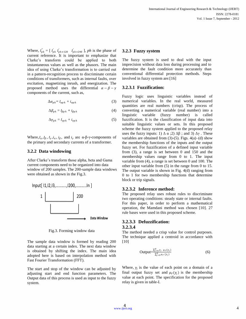
3.2.2 Data windowing
After Clarke’s transform those alpha, beta and Gama
current components need to be organized into data
window of 200 samples. The 200-sample data windows
were obtained as shown in the Fig.3.
Fig.3. Forming window data
The sample data window is formed by reading 200
data starting at a certain index. The next data window
is obtained by shifting the index. The main idea
adopted here is based on interpolation method with
Fast Fourier Transformation (FFT).
The start and stop of the window can be adjusted by
adjusting start and end function parameters. The
Output data of this process is used as input to the fuzzy
system.
3.2.3 Fuzzy system
The fuzzy system is used to deal with the input
imprecision without data loss during processing and to
determine the fault condition more accurately than
conventional differential protection methods. Steps
involved in fuzzy system are:[16]
3.2.3.1 Fuzzification:
Fuzzy logic uses linguistic variables instead of
numerical variables. In the real world, measured
quantities are real numbers (crisp). The process of
converting a numerical variable (real number) into a
linguistic variable (fuzzy number) is called
fuzzification. It is the classification of input data into
suitable linguistic values or sets. In this proposed
scheme the fuzzy system applied to the proposed relay
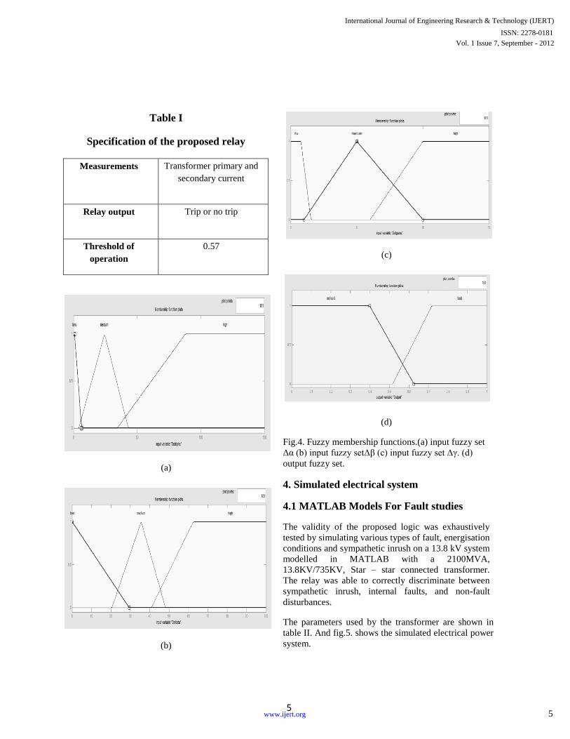
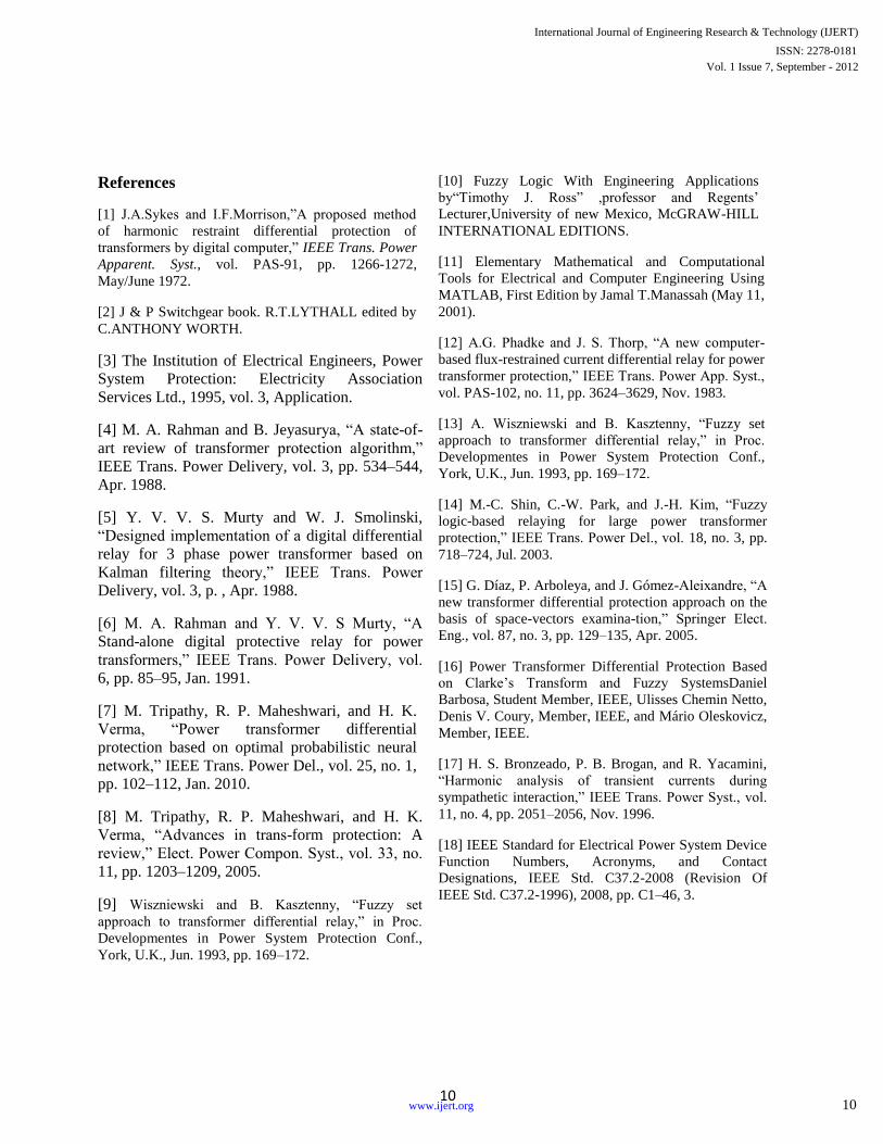
uses the fuzzy inputs: 1) Δ α ;2) Δβ ; and 3) Δγ . These
variables are obtained from (3)-(5). Figs. 4(a)–(d) show
the membership functions of the inputs and the output
fuzzy set. For fuzzification of a defined input variable
from (3), a range is set between 0 and 150 and the
membership values range from 0 to 1. The input
variable from (4), a range is set between 0 and 100. The
other input variable from (5) in the range from 0 to 15.
The output variable is shown in Fig. 4(d) ranging from
0 to 1 for two membership functions that determine
block or trip signals.
3.2.3.2 Inference method: The proposed relay uses robust rules to discriminate
two operating conditions: steady state or internal faults.
For this paper, in order to perform a mathematical
operation, the Mamdani method was chosen [10]. 27
rule bases were used in this proposed scheme.
3.2.3.3 Defuzzification:
3.2.3.4 The method needed a crisp value for control purposes.
The technique applied a centroid in accordance with
[10]
Output= 𝑦𝑗 𝜇𝐹
𝑁𝑗=0 (𝑦𝑗 )
𝜇𝐹𝑁𝑗=0 (𝑦𝑗 )
(6)
Where, 𝑦𝑗 is the value of each point on a domain of a
final output fuzzy set and 𝜇𝐹(𝑦𝑗 ) is the membership
value at each point. The specification for the proposed
relay is given in table-I.
International Journal of Engineering Research & Technology (IJERT)
Vol. 1 Issue 7, September - 2012ISSN: 2278-0181
4www.ijert.org
5
Table I
Specification of the proposed relay
Measurements Transformer primary and
secondary current
Relay output Trip or no trip
Threshold of
operation
0.57
(a)
(b)
(c)
(d)
Fig.4. Fuzzy membership functions.(a) input fuzzy set
Δα (b) input fuzzy setΔβ (c) input fuzzy set Δγ. (d)
output fuzzy set.
4. Simulated electrical system
4.1 MATLAB Models For Fault studies
The validity of the proposed logic was exhaustively
tested by simulating various types of fault, energisation
conditions and sympathetic inrush on a 13.8 kV system
modelled in MATLAB with a 2100MVA,
13.8KV/735KV, Star – star connected transformer.
The relay was able to correctly discriminate between
sympathetic inrush, internal faults, and non-fault
disturbances.
The parameters used by the transformer are shown in
table II. And fig.5. shows the simulated electrical power
system.
International Journal of Engineering Research & Technology (IJERT)
Vol. 1 Issue 7, September - 2012ISSN: 2278-0181
5www.ijert.org

6
Fig.5. simulated electric power system
Table II
Transformer parameters under no-fault
condition
S.No Specification Value
1. Primary voltage 13.8KV
2. Secondary Voltage 735KV
3. Primary resistance (p.u) 0.002
4. Secondary resistance(p.u) 0.002
5. Primary inductance (p.u) 0.08
6. Secondary inductance (p.u) 0.08
7. Nominal power of
transformer
2100MVA
8. Transformer Frequency 50
9. Magnetization resistance 500
10. Winding type Star –star
5. Hardware implementation
5.1 Hardware description
The main purpose of this section is to explain how to
design the fuzzy based differential proto type relay for
the protection of power transformer including
hardware and software implementation.
The system has been implemented using AT89S52,
PIC16F877A. These were employed for developing the
prototype relay, with all the coding done using
microcontroller C and PIC basic languages. Kiel
uVision3 and PIC Simulator IDE, these two software
been used for loading the programs on chip. A special
terminal program, developed in C language was used
to apply the current input signals to the prototype relay
in real-time by using of MAX232 serial data
communication. The logic is deterministic,
computationally efficient, secure and highly reliable.
Before looking the details of designing this project, it
is best to start with brief review of the system design.
Figure.6 shows the complete system design of the
proposed proto type relay.
Fig.6. Block diagram of the system
5.1.1 Circuit diagram for the proto type
relay
Fig.7. Interfacing of MAX232 and AT89S52
International Journal of Engineering Research & Technology (IJERT)
Vol. 1 Issue 7, September - 2012ISSN: 2278-0181
6www.ijert.org

7
Fig.8. Interfacing facing of
AT89S52,PIC16F877A,LCD and relay
5.1.2 MAX232
Features
1) Operates From a Single 5-V Power Supply
2) With 1.0-µF Charge-Pump Capacitors.
3) It is very much useful for serial data
communication.
4) Two Drivers and Two Receivers
5) ±30-V Input Levels
6) Low Supply Current ...8 mA Typical.
Pin configuration
5.1.3 AT89S52
The AT89S52 is a low-power, high-performance
CMOS 8-bit microcontroller with 8K bytes of in-
system programmable Flash memory. The device is
manufactured using Atmel’s high-density non-volatile
memory technology and is compatible with the industry
standard 80C51 instruction set and pin Out. The on-chip
Flash allows the program memory to be reprogrammed
in-system or by a conventional non-volatile memory
programmer. By combining a versatile 8-bit CPU with
in-system programmable Flash on a monolithic chip, the
Atmel AT89S52 is a powerful microcontroller which
provides a highly flexible and cost effective solution
many embedded control applications.
Features
1) Compatible with MCS®-51 Products
2) 8K Bytes of In-System Programmable (ISP)
FlashMemory-Endurance:10,000 Write/Erase
Cycles
3) 4.0V to 5.5V Operating Range
4) Fully Static Operation: 0 Hz to 33 MHz
5) Three-level Program Memory Lock
6) 256 x 8-bit Internal RAM
7) 32 Programmable I/O Lines
8) Three 16-bit Timer/Counters
9) Eight Interrupt Sources
10) Full Duplex UART Serial Channel
11) Low-power Idle and Power-down Modes
12) Interrupt Recovery from Power-down Mode
13) Watchdog Timer
14) Dual Data Pointer
15) Power-off Flag
16) Fast Programming Time
17) Flexible ISP Programming (Byte and Page
Mode)
Pin Configuration
International Journal of Engineering Research & Technology (IJERT)
Vol. 1 Issue 7, September - 2012ISSN: 2278-0181
7www.ijert.org

8
5.1.4 PIC16F877A
The PIC16x84 is a microcontroller in the PIC family of
controllers produced by Microchip Technology. The
PIC16x84 became popular in many hobbyist
applications because it uses a serial programming
algorithm that lends itself to very simple programmers.
Additionally, it uses EEPROM memory, so it's easy to
erase and requires no special tools to do so. It also has a
64 byte EEPROM for storage of user data. The
PIC16x84 was easily tweaked to allow crackers to Then
produce the source assembly files.
Pin configuration
5.1.5 16 x 2 Character LCD
FEATURES
1) 5 x 8 dots with cursor
2) Built-in controller (KS 0066 or Equivalent)
3) + 5V power supply (Also available for + 3V)
4) 1/16 duty cycle
5) B/L to be driven by pin 1, pin 2 or pin 15, pin
16 or A.K (LED)
6) N.V. optional for + 3V power supply
6. hardware pictures
7. Result and discussion
The main purpose of this section is to present some
results regarding the proposed algorithm. Various
different tests were simulated for distinct operating
conditions of power transformer shown in bellow. For
brevity, only few cases were taken here.
(a)
(b)
Fig.8.(a) Transformer primary and secondary current
for the inrush condition.(b) Relay output.
The figure 8.(a) shows the transformer inrush currents
transients in the primary side during energization of the
transformer without any load. And the 8. (b) Shows the
relay output. From the figure it is observed that the
proposed technique is deterministic. The value zero
Conclude that in case inrush current the proposed relay
is not giving any trip signal to the circuit breaker.
(a)
International Journal of Engineering Research & Technology (IJERT)
Vol. 1 Issue 7, September - 2012ISSN: 2278-0181
8www.ijert.org

9
(b)
Fig.9(a) Transformer secondary and primary current
for energisation under fault condition.(b) Relay output.
Fig-9.(a) shows the transformer primary and secondary
side during energization of the transformer under fault
condition. And the 9.(b) shows the relay output. It can
be observed that in the energization under fault
condition it attains the value above the threshold value,
so it gives the trip signal to the circuit breaker.
(a)
(b)
Fig.10(a) Transformer secondary and primary current
for no fault condition.(b) Relay output.
Fig-10.(a) shows the primary and secondary current of
the transformer during normal operating condition. And
from the fig-10(b) shows the relay output, which can
conclude that at the normal condition the proposed
method sent no trip signal.
The proposed relay was able to discriminate between
inrush, fault and no-fault conditions. Thus the proposed
technique is deterministic, secure and highly reliable in
both simulation environments as well as in laboratory
test. Table-III shows the experimental results for the
proposed prototype relay. These are given bellow.
Table-III Experimental results for relay
Various cases Relay output
Inrush current No trip
Energization under fault Trip
No-fault No trip
8.conclusion
The paper presents a new algorithm differential
protection power transformer based on fuzzy logic and
application of Clarke’s transform shows a vastly
improved performance over conventional techniques.
The obtained result shows that the proposed fuzzy
based differential relay represents a proper action. It
can operate with proper sensitivity and even without
tap changing effect using fuzzy logic with Clarke’s
transform that is proposed here solves this problem.
Thus the use of fuzzy logic with Clarke’s transform
can make it possible to extend reliability and
sensitivity of differential relays for power transformer.
Acknowledgment
The authors would like to thank the Department of
Electrical engineering, NATIONAL INSTITUTE OF
TECHNOLOGY AGARTALA, INDIA, for research
facilities provided to conduct this research work.
International Journal of Engineering Research & Technology (IJERT)
Vol. 1 Issue 7, September - 2012ISSN: 2278-0181
9www.ijert.org
10
References
[1] J.A.Sykes and I.F.Morrison,”A proposed method
of harmonic restraint differential protection of
transformers by digital computer,” IEEE Trans. Power
Apparent. Syst., vol. PAS-91, pp. 1266-1272,
May/June 1972.
[2] J & P Switchgear book. R.T.LYTHALL edited by
C.ANTHONY WORTH.
[3] The Institution of Electrical Engineers, Power
System Protection: Electricity Association
Services Ltd., 1995, vol. 3, Application.
[4] M. A. Rahman and B. Jeyasurya, “A state-of-
art review of transformer protection algorithm,”
IEEE Trans. Power Delivery, vol. 3, pp. 534–544,
Apr. 1988.
[5] Y. V. V. S. Murty and W. J. Smolinski,
“Designed implementation of a digital differential
relay for 3 phase power transformer based on
Kalman filtering theory,” IEEE Trans. Power
Delivery, vol. 3, p. , Apr. 1988.
[6] M. A. Rahman and Y. V. V. S Murty, “A
Stand-alone digital protective relay for power
transformers,” IEEE Trans. Power Delivery, vol.
6, pp. 85–95, Jan. 1991.
[7] M. Tripathy, R. P. Maheshwari, and H. K.
Verma, “Power transformer differential
protection based on optimal probabilistic neural
network,” IEEE Trans. Power Del., vol. 25, no. 1,
pp. 102–112, Jan. 2010.
[8] M. Tripathy, R. P. Maheshwari, and H. K.
Verma, “Advances in trans-form protection: A
review,” Elect. Power Compon. Syst., vol. 33, no.
11, pp. 1203–1209, 2005.
[9] Wiszniewski and B. Kasztenny, “Fuzzy set
approach to transformer differential relay,” in Proc.
Developmentes in Power System Protection Conf.,
York, U.K., Jun. 1993, pp. 169–172.
[10] Fuzzy Logic With Engineering Applications
by“Timothy J. Ross” ,professor and Regents’
Lecturer,University of new Mexico, McGRAW-HILL
INTERNATIONAL EDITIONS.
[11] Elementary Mathematical and Computational
Tools for Electrical and Computer Engineering Using
MATLAB, First Edition by Jamal T.Manassah (May 11,
2001).
[12] A.G. Phadke and J. S. Thorp, “A new computer-
based flux-restrained current differential relay for power
transformer protection,” IEEE Trans. Power App. Syst.,
vol. PAS-102, no. 11, pp. 3624–3629, Nov. 1983.
[13] A. Wiszniewski and B. Kasztenny, “Fuzzy set
approach to transformer differential relay,” in Proc.
Developmentes in Power System Protection Conf.,
York, U.K., Jun. 1993, pp. 169–172.
[14] M.-C. Shin, C.-W. Park, and J.-H. Kim, “Fuzzy
logic-based relaying for large power transformer
protection,” IEEE Trans. Power Del., vol. 18, no. 3, pp.
718–724, Jul. 2003.
[15] G. Díaz, P. Arboleya, and J. Gómez-Aleixandre, “A
new transformer differential protection approach on the
basis of space-vectors examina-tion,” Springer Elect.
Eng., vol. 87, no. 3, pp. 129–135, Apr. 2005.
[16] Power Transformer Differential Protection Based
on Clarke’s Transform and Fuzzy SystemsDaniel
Barbosa, Student Member, IEEE, Ulisses Chemin Netto,
Denis V. Coury, Member, IEEE, and Mário Oleskovicz,
Member, IEEE.
[17] H. S. Bronzeado, P. B. Brogan, and R. Yacamini,
“Harmonic analysis of transient currents during
sympathetic interaction,” IEEE Trans. Power Syst., vol.
11, no. 4, pp. 2051–2056, Nov. 1996.
[18] IEEE Standard for Electrical Power System Device
Function Numbers, Acronyms, and Contact
Designations, IEEE Std. C37.2-2008 (Revision Of
IEEE Std. C37.2-1996), 2008, pp. C1–46, 3.
International Journal of Engineering Research & Technology (IJERT)
Vol. 1 Issue 7, September - 2012ISSN: 2278-0181
10www.ijert.org

11
International Journal of Engineering Research & Technology (IJERT)
Vol. 1 Issue 7, September - 2012ISSN: 2278-0181
11www.ijert.org
