implementation of electrokinetic based soil desalinization ek desalinization...
TRANSCRIPT
Implementation of Electrokinetic Based Soil DesalinizationBased Soil Desalinization
Christopher J. Athmer, P.E., Brent E Huntsman CPGBrent E. Huntsman, CPG
Terran Corporation
Dustin AndersenOasis Petroleum

Current Remediation T h l i f B i S illTechnologies for Brine Spills
• Dig and Haul Dig and Haul
• Amend and/or FlushProtective of an aquifer ? Chloride?Protective of an aquifer ? Chloride?
• CapGenerally not acceptable to land owner y p
• Others??

Electrokinetic Remediation ?Electrokinetic Remediation ?
• Application of direct current (DC) Application of direct current (DC) electricity to the soil
• Polarized electrodes invoke movement f d i i d i of pore water and ions contained in
the pore water, even in low bili ilpermeability soils
ElectrokineticsElectrokinetics
• Electroosmosis – Movement of pore Electroosmosis Movement of pore water and contaminants toward the cathodecathode
El i i Mi i f i i • Electromigration – Migration of ionic species toward respective electrodes ( i d d i d (anions toward anode, cations toward cathode) by electrical attraction

Principles of ElectrokineticsElectroosmosis = Water Transport from anode to cathodeElectromigration = Ion Transport to the opposite electrode
Soil ParticleSoil Particle
A d
- - - - - -
-+
Soil Particle-
-
++ + + ++ + +-
- +++ Water
Anode
-- -----
Cathode
S il P ti l-
+ ++++ +++- - - -++ Velocity
Profile
Soil ParticleSoil Particle
Soil Particle

Electrokinetic ApplicationsElectrokinetic Applications
• Environmental RemediationEnvironmental Remediation– Heavy Metals (lead, chrome)
– Organic Solvents (with in-situ ZVI)
– Others (arsenic, nitrate, ISCO, bio-amendments)
• Dewatering/Stabilizationg
• Desalinization
• EK works in saturated & unsaturated zoneszones
How EK Desalinization kWorks
• Sodium ions migrate toward the cathode gby electromigration and electroosmosis where they are removed
• Chloride ions migrate toward the anode by electromigration, where they are by electromigration, where they are removed or oxidized to chorine
• The removed cathode and anode streams are combined as brine and disposed/injected or beneficially reuseddisposed/injected or beneficially reused

EK Desalinization Application
B i
Electromigration
Brine
+ -
Electroosmosis
Na+Cl-
R t f i i ti ( l t i ti ) i Rate of ion migration (electromigration) is proportional to voltage gradient and ionic mobility plus electroosmosis flow and any bulk convectional flow.
Anode + Cathode -

Electrode PatternElectrode Pattern
Model simulates removal from a cylinder with no cylinder with no flow boundary and central sink

Field Scale DesignField Scale Design
• Readily available equipment and parts (lowest y q p p (costs)
• Electrodes are installed like miniature wells– Slotted 1” PVC well screen (24 cathodes, 69 anodes)Slotted 1 PVC well screen (24 cathodes, 69 anodes)– DSA wire wrapping as primary electrode– Backfill annulus with cathodic backfill material (example-Loresco
SWS®)I t ll d ith h d li h (G b ®) ll d ill i– Installed with hydraulic push (Geoprobe®) or small drill rig
• Extraction equipment is multi-head peristaltic pumps (peristaltic) operated on a timer
• Passive as possible operation• Site remained saturated with precipitation
providing enough water (some mild flooding)providing enough water (some mild flooding)

EK Desalinization ProcessEK Desalinization Process480 VoltAC Line Feed F J k P
Brine Tote
From Jack Pump Generator
Multi-head Peristaltic
Brine Discharge Pump
Siphon tubes
Anode buss feed
Cathode buss feed(DC)
+-
Pumps
Rectifier
Na+ Electrodes arranged
Cl-
Pore Water
in hexagonal grid
Anode(multiple)
Cathode(multiple)
Pore Water
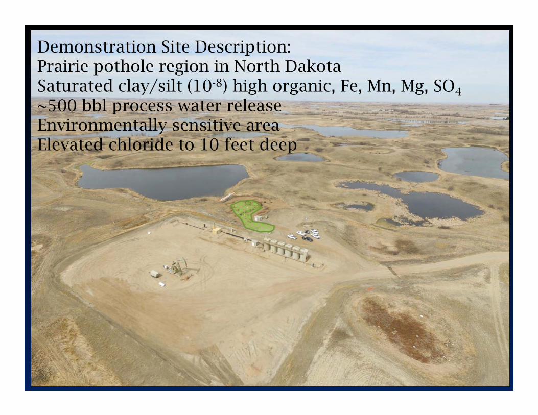
Demonstration Site Description:Prairie pothole region in North DakotaSaturated clay/silt (10-8) high organic, Fe, Mn, Mg, SO4
~500 bbl process water releaseEnvironmentally sensitive areaEnvironmentally sensitive areaElevated chloride to 10 feet deep

First action was to isolate the small slough from larger, begin pumping g g , g p p gaffected water from the small slough, and excavate contaminated soil around release point and above the sloughrelease point and above the slough.

What a muck hole !(effectively a swamp)

Area was covered with geofabric, g ,geogrid, and cover rock to confine the contaminated soil and create a firm working surface Surface materials will working surface. Surface materials will be removed at completion.
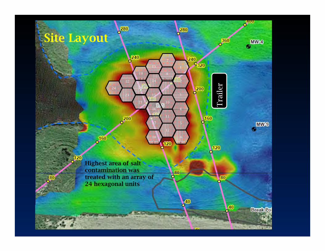
Site Layout
7
1
19
13
8
3
2
16
10
4
22
20
14
15
9
23
21
24
Tra
iler
Tra
iler
17
16
11
12
5
4
18 6
Highest area of salt contamination was treated with an array of 24 hexagonal units

Installation was accomplished Installation was accomplished using a Geoprobe rig
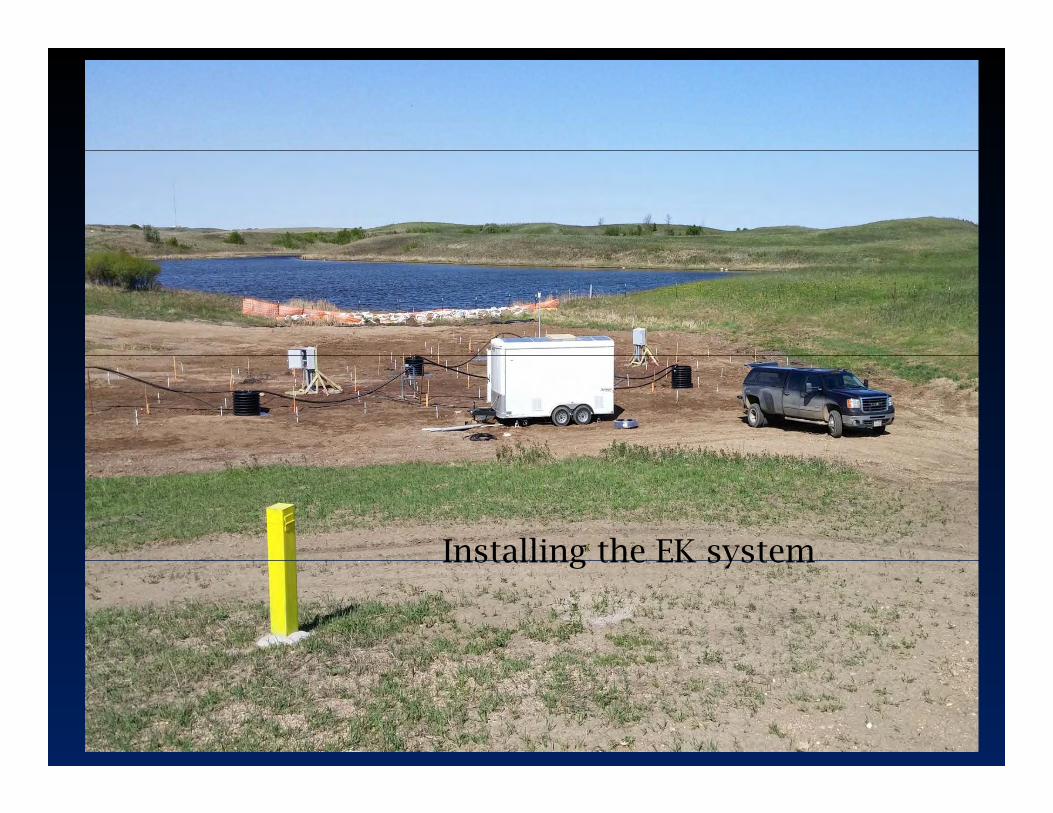
Installing the EK systemInstalling the EK system

Site after completed installation

O ti T D tOperations To Date
System began operations June 2, 2016System shut down for winter October 13, 2016


100050
Voltage and Current Trends over Time
800
900
40
45
Attempted current at 800+ amps but cathode well temps were too high so current was reduced
70035
500
600
25
30
Am
ps
Volt
age
300
400
15
20
100
200
5
10
005/11/16 6/11/16 7/12/16 8/12/16 9/12/16 10/13/16 11/13/16
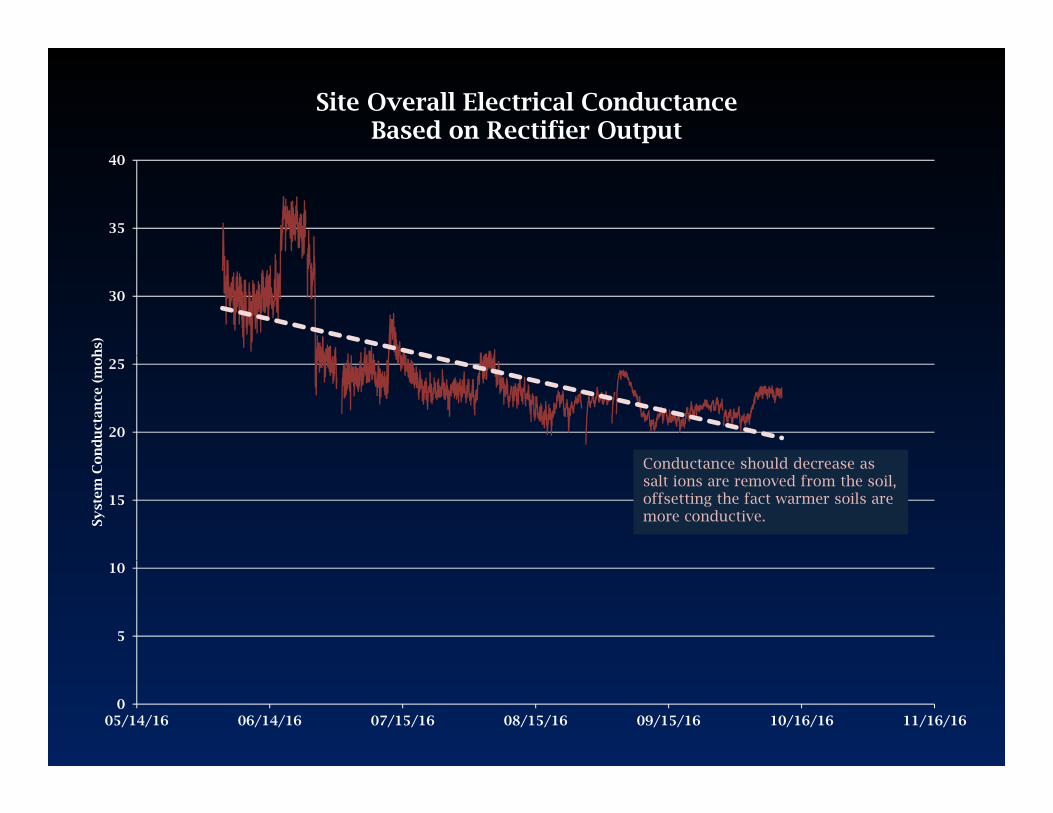
Site Overall Electrical ConductanceBased on Rectifier Output
35
40
30
hs)
20
25
on
du
ctan
ce (
moh
C d h ld d
15
Syst
em C
o Conductance should decrease as salt ions are removed from the soil,offsetting the fact warmer soils are more conductive.
5
10
005/14/16 06/14/16 07/15/16 08/15/16 09/15/16 10/16/16 11/16/16

600,000
Discharge Tanks Conductivity
500,000
600,000
South Tank North Tank
I d d ti it
400,000
cm)
Increased conductivity of extracted water as expected
300,000
nd
uct
ivit
y (
us/
c
200,000Tan
k C
on
100,000
005/20/16 06/20/16 07/21/16 08/21/16 09/21/16 10/22/16

100
Field TemperaturesNear North and South Tanks
90
100
North Temp #1 Cathode
South Temp #2 Anode
Attempted current at 800+ amps but cathode well temps were too high so current was reduced
70
80
50
60
per
atu
re (D
eg C
)
30
40
Tem
p
10
20
05/20/16 6/20/16 7/21/16 8/21/16 9/21/16 10/22/16

Chloride RemovalChloride Removal
– Model predicts 300+ days for the chloride to reach p yanodes (2D, cylindrical, transient)
– Soil samples were collected after 110 days of tioperation
– Matched samples collected before and end of summer operations (8 locations, 2 depths, n=16) summer operations (8 locations, 2 depths, n 16) show 41% removal
• Site conductance data confirms chloride removal
EM Surveys inconclusive• EM Surveys inconclusive
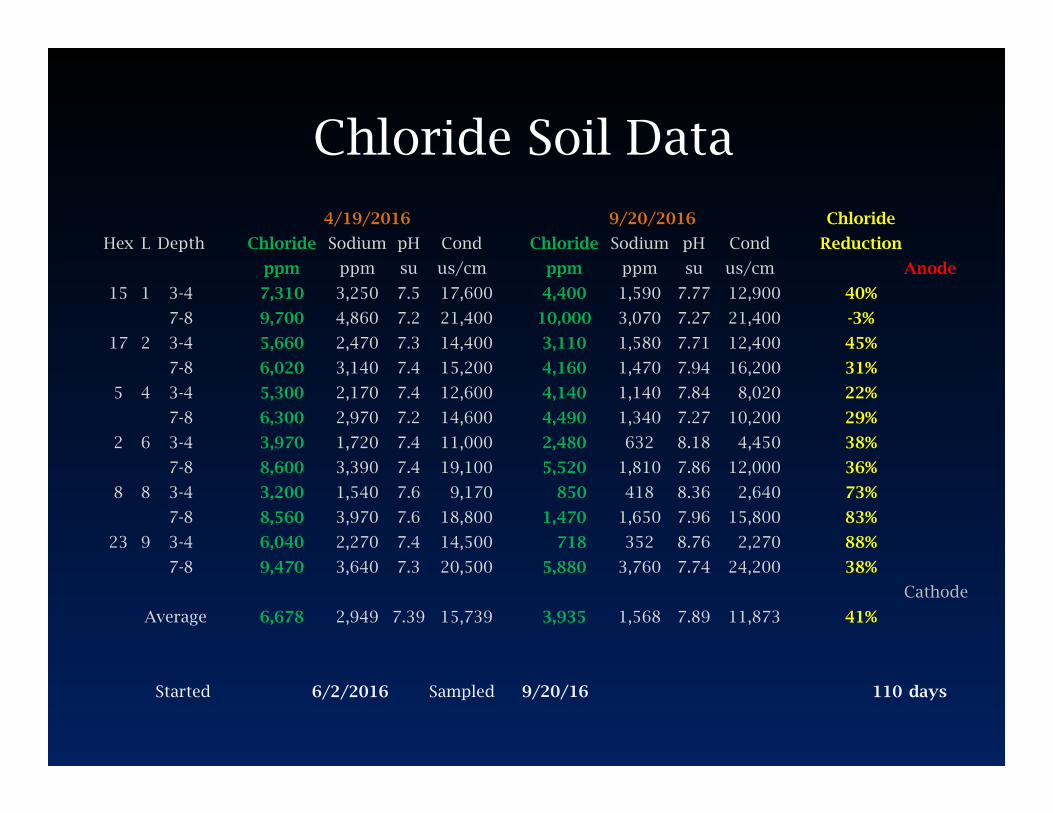
Chloride Soil DataChloride Soil Data
4/19/2016 9/20/2016 Chloride
Hex L Depth Chloride Sodium pH Cond Chloride Sodium pH Cond Reduction
ppm ppm su us/cm ppm ppm su us/cm Anode
15 1 3-4 7,310 3,250 7.5 17,600 4,400 1,590 7.77 12,900 40%
7-8 9,700 4,860 7.2 21,400 10,000 3,070 7.27 21,400 -3%
17 2 3-4 5,660 2,470 7.3 14,400 3,110 1,580 7.71 12,400 45%
7-8 6,020 3,140 7.4 15,200 4,160 1,470 7.94 16,200 31%
5 4 3-4 5,300 2,170 7.4 12,600 4,140 1,140 7.84 8,020 22%
7-8 6,300 2,970 7.2 14,600 4,490 1,340 7.27 10,200 29%
2 6 3-4 3,970 1,720 7.4 11,000 2,480 632 8.18 4,450 38%
7-8 8,600 3,390 7.4 19,100 5,520 1,810 7.86 12,000 36%
8 8 3-4 3,200 1,540 7.6 9,170 850 418 8.36 2,640 73%
7-8 8,560 3,970 7.6 18,800 1,470 1,650 7.96 15,800 83%
23 9 3-4 6,040 2,270 7.4 14,500 718 352 8.76 2,270 88%
7-8 9,470 3,640 7.3 20,500 5,880 3,760 7.74 24,200 38%
Cathode
Average 6,678 2,949 7.39 15,739 3,935 1,568 7.89 11,873 41%
Started 6/2/2016 Sampled 9/20/16 110 days

Lessons Learned to DateLessons Learned to Date
• Chlorine gas generated at anode Chlorine gas generated at anode (expected)
• Choose materials and pump • Choose materials and pump equipment wisely
N d d i llh d • Needed to upsize wellhead generator to handle jack pump and rectifier
For ConsiderationFor Consideration
• Use of plastic venturi pumps down hole for • Use of plastic venturi pumps down hole for fluid management?
• Can the system be operated to convert all Can the system be operated to convert all chloride to chlorine?
• Reverse-pulse operations may even out the Reverse pulse operations may even out the conductivity gradients and increase chloride removal
• Low voltage, high current DC requirements begs solar power

ConclusionsConclusions
• EK desalinization is working at the • EK desalinization is working at the demonstration site
• Regulators and Corporate on board
• If it works at this site, it can work at most any siteany site.

Many Thanks!Many Thanks!
• To Oasis Petroleum for believing in this process g pand allowing the trial at this site
• To US Fish and Wildlife Service and the North D k t D t f H lth f id d tDakota Dept of Health for guidance and support
• Habitat Management, American Engineering and Testing, Vertex, Three Forks Environmental for site Testing, Vertex, Three Forks Environmental for site support