implementation of an interrupt-driven osek …raimue/documents/sloth-cm3.pdf · implementation of...
TRANSCRIPT

Implementation of an Interrupt-DrivenOSEK Operating System Kernel on an
ARM Cortex-M3 Microcontroller
Studienarbeit im Fach Informatik
vorgelegt von
Rainer Müller
geboren am 14. Februar 1987 in Erlangen
Angefertigt am
Lehrstuhl für Informatik 4 – Verteilte Systeme und BetriebssystemeFriedrich-Alexander-Universität Erlangen-Nürnberg
Betreuer:
Dipl.-Inf. Wanja HoferDr.-Ing. Daniel Lohmann
Prof. Dr.-Ing. habil. Wolfgang Schröder-Preikschat
Beginn der Arbeit: 01.05.2011Abgabe der Arbeit: 27.10.2011


Erklärung
Ich versichere, dass ich die Arbeit ohne fremde Hilfe und ohne Benutzung anderer als derangegebenen Quellen angefertigt habe und dass die Arbeit in gleicher oder ähnlicher Form nochkeiner anderen Prüfungsbehörde vorgelegen hat und von dieser als Teil einer Prüfungsleistungangenommen wurde. Alle Ausführungen, die wörtlich oder sinngemäß übernommen wurden, sindals solche gekennzeichnet.
Erlangen, 27.10.2011

Zusammenfassung
Ein Betriebssystem unterscheidet gewöhnlich zwischen Threads, die von einem Schedulerin Software verwaltet werden, und Interrupthandler, die von der Hardware eingeplant undeingelastet werden. Diese Unterscheidung trägt Probleme für Echtzeitsysteme mit sich, daInterrupt Handler mit niedriger Priorität Threads mit hoher Priorität unterbrechen kön-nen. Das Sloth-Konzept stellt einen Weg vor, dieses Problem durch die Implementierungvon beiden, Interrupthandlern und Threads, als Interrupt zu lösen. Dies beseitigt den Un-terschied zwischen den beiden Arten von Kontrollflüssen und diese Vereinfachung erlaubtes, das Einplanen und Einlasten von Threads vom Unterbrechungssubsystem der Hardwareerledigen zu lassen.
Im Rahmen dieser Arbeit wurde dieses Sloth-Konzept als interrupt-gesteuertes Be-triebssystem auf Basis der OSEK-Spezifikation für den ARM Cortex-M3 Mikrocontrollerimplementiert. Dies beinhaltet auch die Untersuchung, wie das Sloth-Konzept auf der zurVerfügung stehenden Hardware umgesetzt werden kann und wie die Hardware-Komponentengenutzt werden müssen. Diese fertige Implementierung wird dann evaluiert und mit einemherkömmlichen System mit einem software-gestütztem Scheduler verglichen, um die posi-tiven Effekte dieses Konzepts auf die Verwaltung von Threads zu bestätigen. Ebenso wirdder Einfluss der Hardware-Architektur auf das Design und die Implementierung von Slothuntersucht.
Abstract
An operating system usually distinguishes between threads managed by a software sched-uler and interrupt service routines, scheduled and dispatched by an interrupt controller. Thisparadigm has inherent problems for real-time systems as low-priority interrupt routines caninterrupt high-priority threads. The Sloth concept proposes to overcome this issue byimplementing both interrupt handlers and threads as interrupts, which are scheduled anddispatched by hardware. This eliminates the difference between the two types of control flowsby introducing a unified abstraction. With this simplification, scheduling and dispatching ofthreads can be managed completely by the interrupt subsystem in hardware.
In the scope of this thesis, this Sloth concept was implemented as an interrupt-drivenoperating system conforming to the OSEK specification on the ARM Cortex-M3 microcon-troller platform. This entails the investigation how the Sloth concept can be implementedwith the provided hardware functionality and how the hardware components need to be uti-lized. This finished implementation is evaluated and compared to another operating systemwith a software-based scheduler in order to confirm the positive effect of this concept on theperformance of thread management. Additionally, this thesis examines the influences of thehardware architecture on the design and implementation of Sloth.

Contents
1 Introduction 11.1 The Sloth Concept . . . . . . . . . . . . . . . . . . . . . . . . . . . . . . . . . . . . 11.2 About OSEK . . . . . . . . . . . . . . . . . . . . . . . . . . . . . . . . . . . . . . . 21.3 Sloth Overview . . . . . . . . . . . . . . . . . . . . . . . . . . . . . . . . . . . . . . 21.4 Requirements on the Interrupt Controller . . . . . . . . . . . . . . . . . . . . . . . 41.5 The ARM Cortex-M3 . . . . . . . . . . . . . . . . . . . . . . . . . . . . . . . . . . 4
1.5.1 Architecture Overview . . . . . . . . . . . . . . . . . . . . . . . . . . . . . . 41.5.2 The Atmel SAM3U . . . . . . . . . . . . . . . . . . . . . . . . . . . . . . . . 6
1.6 Outline of This Thesis . . . . . . . . . . . . . . . . . . . . . . . . . . . . . . . . . . 6
2 The Nested Vectored Interrupt Controller 72.1 Exceptions and Interrupts . . . . . . . . . . . . . . . . . . . . . . . . . . . . . . . . 72.2 Programming the NVIC . . . . . . . . . . . . . . . . . . . . . . . . . . . . . . . . . 72.3 Exception Handling and Preemption . . . . . . . . . . . . . . . . . . . . . . . . . . 102.4 Summary . . . . . . . . . . . . . . . . . . . . . . . . . . . . . . . . . . . . . . . . . 10
3 Design and Implementation 133.1 Sloth Implementation Overview . . . . . . . . . . . . . . . . . . . . . . . . . . . . . 13
3.1.1 Utilization of the SAM3U Hardware . . . . . . . . . . . . . . . . . . . . . . 133.1.2 System Configuration . . . . . . . . . . . . . . . . . . . . . . . . . . . . . . 14
3.2 Basic Tasks . . . . . . . . . . . . . . . . . . . . . . . . . . . . . . . . . . . . . . . . 153.3 Extended Tasks . . . . . . . . . . . . . . . . . . . . . . . . . . . . . . . . . . . . . . 193.4 Resource Management . . . . . . . . . . . . . . . . . . . . . . . . . . . . . . . . . . 243.5 Alarms . . . . . . . . . . . . . . . . . . . . . . . . . . . . . . . . . . . . . . . . . . . 283.6 Summary . . . . . . . . . . . . . . . . . . . . . . . . . . . . . . . . . . . . . . . . . 29
4 Evaluation 314.1 Performance Evaluation . . . . . . . . . . . . . . . . . . . . . . . . . . . . . . . . . 31
4.1.1 Measurement Setup . . . . . . . . . . . . . . . . . . . . . . . . . . . . . . . 314.1.2 System Configuration . . . . . . . . . . . . . . . . . . . . . . . . . . . . . . 334.1.3 Test Scenarios . . . . . . . . . . . . . . . . . . . . . . . . . . . . . . . . . . 334.1.4 Basic-Task System . . . . . . . . . . . . . . . . . . . . . . . . . . . . . . . . 344.1.5 Extended-Task System . . . . . . . . . . . . . . . . . . . . . . . . . . . . . . 354.1.6 Mixed Task System . . . . . . . . . . . . . . . . . . . . . . . . . . . . . . . 374.1.7 Summary of the Performance Evaluation . . . . . . . . . . . . . . . . . . . 38
4.2 Comparison with the Reference Implementation on the TriCore Platform . . . . . 394.2.1 The Infineon TriCore . . . . . . . . . . . . . . . . . . . . . . . . . . . . . . . 39
i

4.2.2 Similarities and Differences in the Implementation of the System Services . 404.2.3 Evaluation of the Test Cases . . . . . . . . . . . . . . . . . . . . . . . . . . 424.2.4 Summary of the Comparison with the Reference Implementation on the
TriCore Platform . . . . . . . . . . . . . . . . . . . . . . . . . . . . . . . . . 434.3 Limitations . . . . . . . . . . . . . . . . . . . . . . . . . . . . . . . . . . . . . . . . 434.4 Summary . . . . . . . . . . . . . . . . . . . . . . . . . . . . . . . . . . . . . . . . . 43
5 Conclusion 45
Bibliography 47
ii


Chapter 1
Introduction
The scheduler is a key component in any operating system, as it is responsible for the managementof different control flows. A scheduler usually switches between several threads synchronouslyactivated by software. Additionally, interrupt service routines (ISRs) interrupt the CPU at anytime asynchronously when signaled by the hardware. Using these two mechanisms togetherestablishes inherently dual priority spaces, in which ISRs always have a higher priority thanthreads as they are running at the lowest hardware priority. Thus, an ISR meant to have alow priority can preempt a high-priority thread. This issue is known as rate-monotonic priorityinversion [1]. The Sloth concept introduced in [2, 3] proposes to solve this problem by removingthe distinction between threads and interrupts. By implementing all control flows in the system asinterrupt handlers, the interrupt subsystem hardware can do the scheduling work. In traditionalsystems with a software scheduler, ISRs always have a higher priority as all threads. In Sloth,the unified priority space of threads and ISRs allows arbitrary distribution of priorities betweenthem, without implying restrictions on the precedence of asynchronous over synchronous controlflows.
1.1 The Sloth Concept
In Sloth, both types of control flows—threads and interrupt handlers—are implemented asinterrupts. These threads running as ISRs are scheduled and dispatched by an interrupt controllerin hardware, eliminating the need for a software scheduler completely. In this system, threadsand interrupts share a single priority space managed by the hardware, avoiding the problem ofrate-monotonic priority inversion as described above.
The implementation of the Sloth concept targets an event-driven embedded system, imple-menting the OSEK OS specification as an example. The offered API is the same as in traditionalsystems with a software-based scheduler by using this established standard; it is therefore trivialto port applications to run using the Sloth kernel. The description will stick to the terminologyand system services of OSEK, although this concept can be applied in general to any event-drivenreal-time operating system.
1

OSEK OS
Control Flows
ISRs Cat. 2
Kernel Sync
ISRs Cat. 1 Tasks
Full Preemption Mixed Preemption No Preemption Multiple Tasks Per Prio
BCC2, ECC2
Multiple Activations
BCC2, ECC2
Alarms
Activate Task Set Event
ECC1, ECC2
Exec Callback
Coordination
Resources
BCC2, ECC1, ECC2
Events
ECC1, ECC2
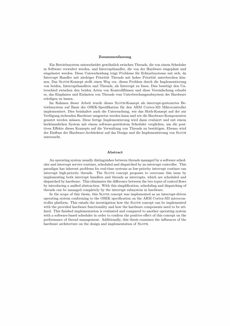
Figure 1.1: Feature diagram of the OSEK OS specification. Features mandatory in a conformanceclass other than BCC1 are marked with the corresponding classes below that feature. Featuretypes include mandatory features (filled circle), optional features (hollow circle), minimum-onefeature sets (filled arc), and exactly-one feature sets (hollow arc) [2].
1.2 About OSEK
OSEK1 is a standard for operating systems in the automotive industry. The specification for theOSEK OS [4] defines an interface to the operating system offering the necessary functionality forevent-driven control systems. An overview of the provided features is given in Figure 1.1.
The offered system functionality includes control flow abstraction by use of tasks with differentpreemption policies that configure whether a higher-priority task can preempt another currentlyexecuting task (full preemption) or not (no preemption). This can also be configured individuallyfor each task (mixed preemption). Optionally, the OS stores multiple activation requests fortasks and more than one task can share the same priority. Interrupt service routines (ISRs) aredispatched by hardware and are partitioned into two groups. ISRs of category 1 are not allowedto use any system services, while category-2 ISRs can use them. Synchronization is possibleby acquisition of resources implementing the OSEK priority ceiling protocol to avoid priorityinversion. Tasks are available in two types, where extended tasks have the same functionality asbasic tasks, but can also yield the CPU and wait until a certain event occurs, which is signaledby another task. Alarms can activate tasks or execute callbacks after a specific period of time.
In order to build a highly scalable and portable system, the OSEK OS specification definesmultiple conformance classes as shown in Figure 1.1. This allows partial implementation of thespecification. Each conformance class defines a minimum set of features which are determinedby the type of tasks present in the application, support for multiple activations of the same task,and the number of tasks per priority. These features are chosen and configured statically; thatis, the tasks, ISRs, and their priorities as well as the system’s features are configured at compiletime.
1.3 Sloth Overview
In a system implementing the Sloth concept, each task and ISR will be assigned to an interruptsource with the configured priority. ISRs are activated by the hardware system as usual, whereasfor tasks, two methods of activation are possible. On the one hand, they can be started syn-
1German acronym for “Offene Systeme und deren Schnittstellen für die Elektronik im Kraftfahrzeug”, trans-lates to “open systems and corresponding interfaces for automotive electronics”
2

CPU Prio Level
t
0
1
2
3
4
t1 t2 t3 t4 t5 t6 t7 t8
init()
enableIRQs()
Task1Act(Task3)
Task3 E
ISR2
Term()
ISR2 iret
Task1SetAlarm(A1)
Term()
idle()
Task1E
Alarm1
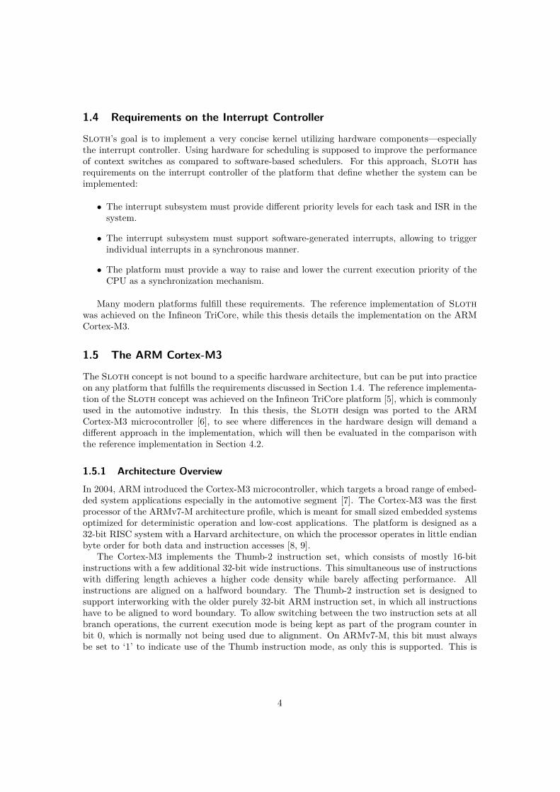
Figure 1.2: Example control flow in a Sloth system. The execution of most system servicesleads to an implicit or explicit altering of the current CPU priority level, which then leads to anautomatic and correct scheduling and dispatching of the control flows by the hardware. [2]
chronously by an OSEK system service, which leads to a software generated interrupt request.On the other hand, hardware devices can signal the corresponding interrupt asynchronously; forexample, tasks triggered by an alarm are invoked by a timer system connected to the interruptsources. Activation of a specific task results in triggering the interrupt source in both cases.
Subsequently, the interrupt controller needs to decide which of the interrupt sources with apending request has the highest priority, which correspond to the assigned control flows—eithertasks or ISRs. If the current execution priority of the CPU is less than the one of the determinedinterrupt source, the CPU needs to be interrupted by an interrupt request. The current execu-tion priority does not always correspond to the executing control flow as it can be raised andlowered for synchronization purposes. If an preemption of the currently running control flow ispossible, the task or ISR corresponding to this interrupt source will be dispatched. This schedul-ing implemented in hardware is responsible for the arbitration of the different priorities betweentasks and ISRs. Rescheduling needs to take place every time an interrupt source is triggered, aninterrupt handler returns, or masking of interrupts is enabled or disabled. Termination of a taskmatches the return from an interrupt handler, which will issue a new arbitration in the interruptcontroller, determining the next interrupt to be handled.
Figure 1.2 shows an example control flow in a system implementing the Sloth concept. Inthis configuration, Task1, ISR2, and Task3 have the priorities 1, 2, and 3, respectively. Afterinitialization of the system, the auto-started Task1 starts running with priority 1 at t1. In itsexecution at t2, Task1 activates the higher-priority Task3, which is immediately dispatched andstarts running with the CPU priority level being raised to 3; preempting the previously runningTask1. At the time t3, a hardware device signals an interrupt request for ISR2. However, as thecurrent execution priority is 3, the execution of ISR2 has to be delayed until Task3 terminates att4. At this point, ISR2 starts executing until it returns from the interrupt at t5 and the preemptedTask1 continues running. When Task1 terminates at t7, no other control flow is currently pending.Thus, the system is running an idle function at the lowest priority level waiting for interrupts.Here, at t8, Task1 is again activated by Alarm1 that was previously set up at t6.
3
1.4 Requirements on the Interrupt Controller
Sloth’s goal is to implement a very concise kernel utilizing hardware components—especiallythe interrupt controller. Using hardware for scheduling is supposed to improve the performanceof context switches as compared to software-based schedulers. For this approach, Sloth hasrequirements on the interrupt controller of the platform that define whether the system can beimplemented:
• The interrupt subsystem must provide different priority levels for each task and ISR in thesystem.
• The interrupt subsystem must support software-generated interrupts, allowing to triggerindividual interrupts in a synchronous manner.
• The platform must provide a way to raise and lower the current execution priority of theCPU as a synchronization mechanism.
Many modern platforms fulfill these requirements. The reference implementation of Slothwas achieved on the Infineon TriCore, while this thesis details the implementation on the ARMCortex-M3.
1.5 The ARM Cortex-M3
The Sloth concept is not bound to a specific hardware architecture, but can be put into practiceon any platform that fulfills the requirements discussed in Section 1.4. The reference implementa-tion of the Sloth concept was achieved on the Infineon TriCore platform [5], which is commonlyused in the automotive industry. In this thesis, the Sloth design was ported to the ARMCortex-M3 microcontroller [6], to see where differences in the hardware design will demand adifferent approach in the implementation, which will then be evaluated in the comparison withthe reference implementation in Section 4.2.
1.5.1 Architecture OverviewIn 2004, ARM introduced the Cortex-M3 microcontroller, which targets a broad range of embed-ded system applications especially in the automotive segment [7]. The Cortex-M3 was the firstprocessor of the ARMv7-M architecture profile, which is meant for small sized embedded systemsoptimized for deterministic operation and low-cost applications. The platform is designed as a32-bit RISC system with a Harvard architecture, on which the processor operates in little endianbyte order for both data and instruction accesses [8, 9].
The Cortex-M3 implements the Thumb-2 instruction set, which consists of mostly 16-bitinstructions with a few additional 32-bit wide instructions. This simultaneous use of instructionswith differing length achieves a higher code density while barely affecting performance. Allinstructions are aligned on a halfword boundary. The Thumb-2 instruction set is designed tosupport interworking with the older purely 32-bit ARM instruction set, in which all instructionshave to be aligned to word boundary. To allow switching between the two instruction sets at allbranch operations, the current execution mode is being kept as part of the program counter inbit 0, which is normally not being used due to alignment. On ARMv7-M, this bit must alwaysbe set to ‘1’ to indicate use of the Thumb instruction mode, as only this is supported. This is
4

r0
r1
r2
r3
r4
r5
r6
r7
r8
r9
r10
r11
General Purpose
General Purpose
General Purpose
General Purpose
General Purpose
General Purpose
General Purpose
General Purpose
General Purpose
General Purpose
General Purpose
General Purpose
r12 / IP Intra-Procedure-Call Register
r13 / SP Stack Pointer
r14 / LR Link Register
r15 / PC Program Counter
Argument/Result Registers
low
high
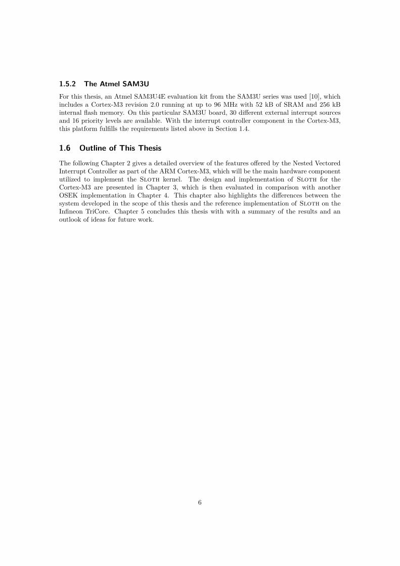
Figure 1.3: Registers in the ARMv7-M architecture.
usually hidden from the programmer as the compiler takes care of this, but can be important forlow-level development, for example while examining addresses on the stack.
ARMv7 specifies 16 registers, each of which is 32 bits wide. They are arranged into 12 general-purpose and 4 special registers as shown in Figure 1.3. All instructions specifying a general-purpose register can access the low registers r0–r7. The high registers r8–r12 are accessiblefrom all 32-bit instructions, but not from all of the 16-bit instructions.
Register r12 is used as a temporary workspace for address calculations during subroutinecalls; register r13 is used as the stack pointer (SP). Stack pointer values have to be aligned toa 4-byte boundary. The register is banked into SP_main and SP_process to allow easy stackswitches for exception handlers and processes. Register r14 is used as a link register (LR), whichholds the return address during a procedure call. The return from a function is initiated byloading the LR value into the program counter PC, which is the special register r15. Additionally,the special program status register (PSR) holds current execution state like flags, which exceptionis currently being handled, and auxiliary state for load multiple and store multiple instructions.
The processor has two operation modes: Thread mode and Handler mode. Thread mode isthe default operation mode after startup, which can run either in privileged or unprivileged levelto limit access to some resources and system configuration. The Handler mode is activated whilehandling an exception and is always executed in privileged access level.
5
1.5.2 The Atmel SAM3UFor this thesis, an Atmel SAM3U4E evaluation kit from the SAM3U series was used [10], whichincludes a Cortex-M3 revision 2.0 running at up to 96 MHz with 52 kB of SRAM and 256 kBinternal flash memory. On this particular SAM3U board, 30 different external interrupt sourcesand 16 priority levels are available. With the interrupt controller component in the Cortex-M3,this platform fulfills the requirements listed above in Section 1.4.
1.6 Outline of This Thesis
The following Chapter 2 gives a detailed overview of the features offered by the Nested VectoredInterrupt Controller as part of the ARM Cortex-M3, which will be the main hardware componentutilized to implement the Sloth kernel. The design and implementation of Sloth for theCortex-M3 are presented in Chapter 3, which is then evaluated in comparison with anotherOSEK implementation in Chapter 4. This chapter also highlights the differences between thesystem developed in the scope of this thesis and the reference implementation of Sloth on theInfineon TriCore. Chapter 5 concludes this thesis with with a summary of the results and anoutlook of ideas for future work.
6

Chapter 2
The Nested Vectored Interrupt Controller
In order to implement the Sloth concept on a platform, the hardware must fulfil the requirementsas stated above in Section 1.4. The ARM Cortex-M3 microcontroller—the target platform for aSloth implementation in the scope of this thesis—includes a tightly-coupled interrupt controllercalled NVIC (Nested Vectored Interrupt Controller) [6, p. 6-1]; this integration of the interruptcontroller into the core allows low-latency interrupt handling. The maximum interrupt latencyamounts to 12 cycles, which describes the time between asserting the interrupt and executing thefirst instruction of the handler [6, p. 3-20].
2.1 Exceptions and Interrupts
The Cortex-M3 provides 16 system exceptions and allows up to 240 different external interruptsources as shown in Figure 2.1. The Reset, NMI (Non-Maskable Interrupt) and HardFault ex-ceptions have fixed priorities that cannot be changed. All other system exceptions and externalinterrupt sources can be assigned to one of up to 256 different priority levels. However, chip man-ufacturers can choose to only implement a fraction of these; for example, on the Atmel SAM3U4Eused for this thesis, 16 different priority levels are available.
The ARM terminology refers to exceptions as running any sort of handler for both synchronousand asynchronous system events. The first 16 exceptions numbered 0 to 15 are reserved by thesystem. They are used for fault handlers (HardFault, MemManage, BusFault, UsageFault),debug functionality (Debug Monitor), supervisor calls (SVCall, PendSV) and for the systemtimer (SysTick). External interrupts start after that, so the external interrupt N will have anexception number of 16+N. The NVIC locates the exception handlers using a static vector table,which is a list of address pointers to the entry points of the handlers.
A priority value of 0 denotes the highest configurable priority, higher values correspond tolower priorities. The maximum value is defined by the implementation. The priorities of Reset,NMI, and HardFault are fixed, so they always have a higher priority than all other exceptions. Ifmultiple exceptions have the same priority and they are pending at the same time, the one withthe lower exception number takes precedence.
2.2 Programming the NVIC
The components of the ARMv7-M architecture are programmed by manipulating memory-mappedregisters. The registers for the NVIC are accessible in a special address range, called the Sys-
7

Exception Interruptnumber number Name Priority
1 Reset −32 NMI −23 HardFault −14 MemManage configurable5 BusFault configurable6 UsageFault configurable
7–10 (reserved)11 SVCall configurable12 Debug Monitor configurable13 (reserved)14 PendSV configurable15 SysTick configurable16 0 External Interrupt 0 configurable17 1 External Interrupt 1 configurable. . . . . . . . . . . .
16+N N External Interrupt N configurable
Figure 2.1: Exceptions provided by the Nested Vectored Interrupt Controller. While the priori-ties of Reset, NMI, and HardFault are fixed, all other priorities can be configured.
tem Control Space (SCS), in which internal system components are configured. Accesses in thismemory region are strongly-ordered, which means the transactions will be performed in programorder. Reading and writing these registers is limited to privileged execution level only. Theseregisters control masking of individual interrupts, set and clear their pending state and configuretheir priorities. Each interrupt source can be triggered asynchronously from connected peripheraldevices or with synchronous instructions from software.
The NVIC provides multiple registers as listed in Table 2.1, controlling interrupt masks andtheir pending state. A particular interrupt can be masked using the ISER (Interrupt Set-EnableRegister) and ICER (Interrupt Clear-Enable Register) bit fields. These are organized in groups,so that each bit in a 32-bit register corresponds to one interrupt. There will be as many bit fieldsas required for the number of interrupt sources implemented by the hardware manufacturer. Asingle read or write operation can retrieve or manipulate the state of each interrupt in the specificgroup. Writing a 1 to the corresponding bit position enables respectively disables the interrupt,and reading the value returns the current state of the interrupts. A disabled interrupt can stillbe asserted as pending, but it will not be dispatched.
Additionally, the NVIC offers bit fields named ISPR (Interrupt Set-Pending Register) andICPR (Interrupt Clear-Pending Register) to read and change the pending state of external in-terrupts. They follow the same write and read semantics as ISER and ICER, where reading thevalue returns the current pending state of the interrupts. Writing to ISPR allows software totrigger interrupts from software. Additionally, STIR (Software Triggered Interrupt Register) canbe used to trigger interrupts in software without privileged access.
Priority levels are configured in the IPR (Interrupt Priority Register) bit fields. The prioritiesof interrupts can be set individually using 8-bit fields, which are organized in groups of four to
8

Register Name Function
ISER Interrupt Set-Enable Register writing bit n allows interrupt #n to be handledICER Interrupt Clear-Enable Register writing bit n prevents handling of interrupt #nISPR Interrupt Set-Pending Register writing bit n marks interrupt #n as pendingICPR Interrupt Clear-Pending Register writing bit n clears pending state of interrupt #nIPR Interrupt Priority Register byte n defines the priority of interrupt #n
Table 2.1: Overview of the memory-mapped registers offered by the NVIC for control of inter-rupts. When the number of supported interrupts is large enough, the actual registers are splitover multiple 32-bit bit fields organized in groups.
fill a 32-bit register. On systems not implementing the full 8 bits, the lower bits of the individualfields ignore writes and read as zero.
In addition to masking individual interrupts as described above, it is also possible to influ-ence interrupt handling globally by setting PRIMASK (priority mask), FAULTMASK, and BASEPRI(base priority):
BASEPRI A register with up to 8 bits with the same width as implemented for the priorityregisters (IPR). This register sets the minimum required base priority for exceptions. Anexception will only be processed immediately if its configured priority value is lower thanthe current BASEPRI value. Of course, it will not be processed if another exception handlerwith an equal or lower priority value is currently active. Remember that lower priorityvalues correspond to higher exception priority.
The highest priority of all active exception handlers and the value of BASEPRI is called thecurrent execution priority, as that is the actual value required for preemption.
BASEPRI_MAX Actually the same register as BASEPRI, but with a conditional write. The requiredbase priority will only be raised and never lowered. Any write to this register trying to seta value higher (i.e., a lower priority level) than the current value will be ignored.
PRIMASK A 1-bit register which, when set, prevents the dispatching of any exception handler butnot the NMI and HardFault. This is equivalent to raising the current execution priorityto 0, the highest configurable value.
FAULTMASK A 1-bit register similar to PRIMASK, but disables dispatching of all exceptions includingthe HardFault and allows only the NMI. This has the same effect as raising the currentexecution priority to −1, the priority of the HardFault exception handler.
These global masking registers are not memory-mapped, but are accessed using instructionsinstead. The MRS and MSR instructions (Move Register to Special and Move Special to Register)read and write special register values, including the BASEPRI value from or to a general-purposeregister. The additional conditon of BASEPRI_MAX can be specified by the encoding of the specialregister passed to the MSR instruction. The 1-bit registers PRIMASK and FAULTMASK are writtenusing the CPSIE and CPSID instructions (Change Processor State), which enable or disable thespecified mask.
9

...
PSR
PC
LR
r12
r3
r2
r1
SP → r0
Figure 2.2: A stack frame as pushed onto the stack by the hardware at exception entry.
2.3 Exception Handling and Preemption
On exception entry, the NVIC automatically resets the pending bit of the dispatched interruptand thus is able to assert this interrupt again as soon as it is handled. Additionally, it storesthe flags, the return address—the value of the PC register at the time of interruption—, andscratch/caller-saved registers on the stack. These registers form the current state of programexecution and will be used to resume where the interruption took place.
The pushed stack frame as shown in Figure 2.2 conforms to the AAPCS (Procedure CallStandard for the ARM Architecture, [11]). This accommodates C/C++ programmers as exceptionhandlers can be written in C/C++ functions that are entered and returned using the callingconvention without requiring special assembler instructions. The difference between a normalfunction call and interrupt handler entry is a special value in the LR register that will invoke thereturn from exception when written to the PC. This value encodes if the interrupted code ran inthread or handler mode and which of the banked stack point registers was in use.
The NVIC is capable of nesting interrupts automatically, which allows dispatching of a newinterrupt handler while another interrupt handler is currently running. Therefore, interruptswill not be masked during execution of a handler. As only interrupts of a higher priority mayinterrupt the currently executing control flow, the dispatching of an interrupt handler raises thecurrent execution priority to the priority of this interrupt. When another interrupt is triggered,its priority will be compared to the current execution priority. If the new interrupt has a higherpriority, the current handler will be suspended and an exception entry for the new handler takesplace. After this handler returns, the control flow of the initial handler will continue where itleft off. Otherwise, if the priority of the new interrupt was lower, the initial handler runs tocompletion before the pending interrupt may be handled.
2.4 Summary
The NVIC as part of the Cortex-M3 fulfills the requirements for a Sloth implementation asdefined in Section 1.4. It provides multiple priority levels, which can be assigned freely to any
10

interrupt source by setting the IPR registers. Also, the interrupt sources can be triggered insoftware by writing the bit pattern to ISPR, which are handled in the same way as if theywould have been triggered from external peripherals. Finally, interrupts can be masked forsynchronization purposes by raising the current execution priority with BASEPRI. Thus, the Slothconcept can be implemented on the ARM Cortex-M3 as presented in the next chapter.
11


Chapter 3
Design and Implementation
The Sloth concept defines the goal of letting the hardware interrupt subsystem do the schedulingof control flows in an event-driven embedded system. The design of the Sloth kernel for theARM Cortex-M3 platform follows the design of the original implementation for the InfineonTriCore [2, 3]. New abstractions have been introduced for some of the functionalities where thedifferent hardware requires a different approach. First, this chapter will discuss the utilizationof the provided hardware systems; then, it explains the implementation of the OSEK systemservices in detail.
3.1 Sloth Implementation Overview
The implemented Sloth system conforms to the classes BCC1 and ECC1 of the OSEK operatingsystem specification as defined in Figure 1.1 in Section 1.2. Therefore the system provides supportfor tasks with statically configured priorities. These tasks are available as two types, of whichbasic tasks always run to completion and extended tasks can block and wait for an event. Asynchronization mechanism exists in form of resources for mutual exclusion in critical sections.For periodic actions, alarms can activate tasks after a timer has elapsed.
3.1.1 Utilization of the SAM3U Hardware
This section gives an overview of how the hardware is used to implement the various systemservices of OSEK in order to achieve the goal of performing the scheduling by hardware.
The main part of the implementation is structured around the NVIC (Nested Vectored In-terrupt Controller) provided with the ARM Cortex-M3. Each task is assigned to one of theinterrupt sources. The external peripherals usually connected to these interrupts should not beused and need to be disabled in the power management to avoid any disturbance. As only theapplication specifies which of the external peripheral components will be in use, the mapping oftasks to interrupt sources is specified in the application configuration. Tasks also have a uniquepriority that will be configured in the NVIC. While in OSEK higher priority values correspondto higher priority, the NVIC defines 0 as the highest priority and higher values correspond tolower priorities. The application configuration always uses the definition of OSEK and maps thespecified priorities to the hardware definition where required.
The basic task management is quite simple on the Cortex-M3. Synchronous task activationfrom software boils down to triggering the corresponding interrupt. This only requires a simple
13
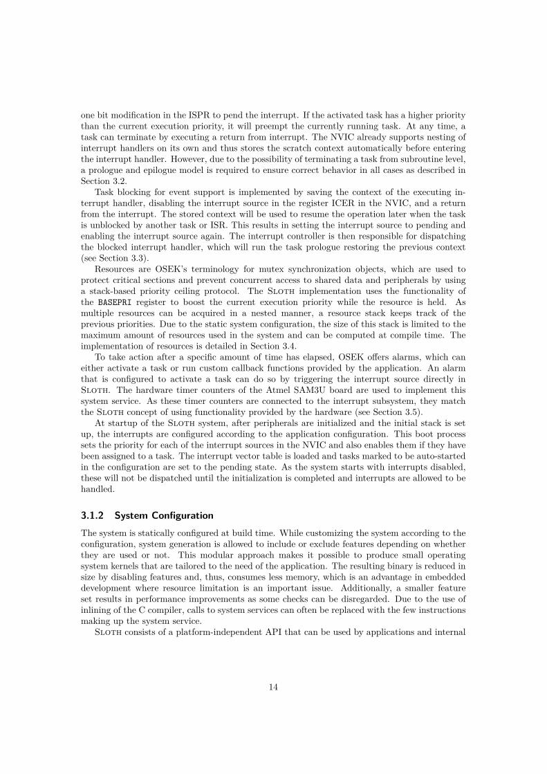
one bit modification in the ISPR to pend the interrupt. If the activated task has a higher prioritythan the current execution priority, it will preempt the currently running task. At any time, atask can terminate by executing a return from interrupt. The NVIC already supports nesting ofinterrupt handlers on its own and thus stores the scratch context automatically before enteringthe interrupt handler. However, due to the possibility of terminating a task from subroutine level,a prologue and epilogue model is required to ensure correct behavior in all cases as described inSection 3.2.
Task blocking for event support is implemented by saving the context of the executing in-terrupt handler, disabling the interrupt source in the register ICER in the NVIC, and a returnfrom the interrupt. The stored context will be used to resume the operation later when the taskis unblocked by another task or ISR. This results in setting the interrupt source to pending andenabling the interrupt source again. The interrupt controller is then responsible for dispatchingthe blocked interrupt handler, which will run the task prologue restoring the previous context(see Section 3.3).
Resources are OSEK’s terminology for mutex synchronization objects, which are used toprotect critical sections and prevent concurrent access to shared data and peripherals by usinga stack-based priority ceiling protocol. The Sloth implementation uses the functionality ofthe BASEPRI register to boost the current execution priority while the resource is held. Asmultiple resources can be acquired in a nested manner, a resource stack keeps track of theprevious priorities. Due to the static system configuration, the size of this stack is limited to themaximum amount of resources used in the system and can be computed at compile time. Theimplementation of resources is detailed in Section 3.4.
To take action after a specific amount of time has elapsed, OSEK offers alarms, which caneither activate a task or run custom callback functions provided by the application. An alarmthat is configured to activate a task can do so by triggering the interrupt source directly inSloth. The hardware timer counters of the Atmel SAM3U board are used to implement thissystem service. As these timer counters are connected to the interrupt subsystem, they matchthe Sloth concept of using functionality provided by the hardware (see Section 3.5).
At startup of the Sloth system, after peripherals are initialized and the initial stack is setup, the interrupts are configured according to the application configuration. This boot processsets the priority for each of the interrupt sources in the NVIC and also enables them if they havebeen assigned to a task. The interrupt vector table is loaded and tasks marked to be auto-startedin the configuration are set to the pending state. As the system starts with interrupts disabled,these will not be dispatched until the initialization is completed and interrupts are allowed to behandled.
3.1.2 System ConfigurationThe system is statically configured at build time. While customizing the system according to theconfiguration, system generation is allowed to include or exclude features depending on whetherthey are used or not. This modular approach makes it possible to produce small operatingsystem kernels that are tailored to the need of the application. The resulting binary is reduced insize by disabling features and, thus, consumes less memory, which is an advantage in embeddeddevelopment where resource limitation is an important issue. Additionally, a smaller featureset results in performance improvements as some checks can be disregarded. Due to the use ofinlining of the C compiler, calls to system services can often be replaced with the few instructionsmaking up the system service.
Sloth consists of a platform-independent API that can be used by applications and internal
14
Application Configuration
tasks = {Task1 = {
type = extended,priority = 1,sam3u_irq = 1,autostart = true
},Task2 = {
type = basic,priority = 2,sam3u_irq = 22
}};resources = {
Resource1 = {used_by = [Task1,Task2]
}};alarms = {
Alarm1 = {activates = Task2
}};
Generated Code
enum {Task1 = 1, // prioTask2 = 2, // prio...Resource1 = 2, // ceiling prioRES_SCHEDULER = 3, // max prio...
};
vectors[] = {prologueTask1,prologueTask2,...
};
void trigger(TaskType id) {if (id == 1) {
NVIC_SetPendingIRQ(1);} else if (id == 2) {
NVIC_SetPendingIRQ(22);}
}...
static analysisand system generation
Analysis:∗ Control flow interaction∗ Priority space∗ Mapping logical to
physical priorities
Generation:∗ Constants∗ Vector table∗ IRQ triggering∗ Task prologues
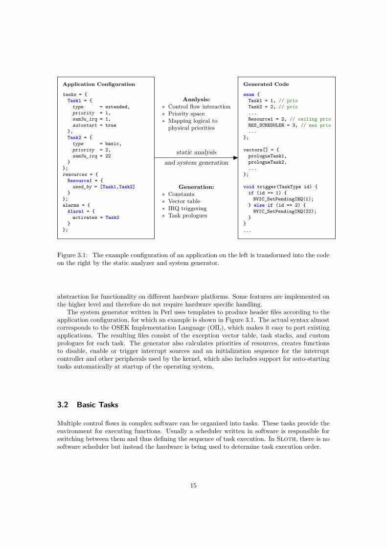
Figure 3.1: The example configuration of an application on the left is transformed into the codeon the right by the static analyzer and system generator.
abstraction for functionality on different hardware platforms. Some features are implemented onthe higher level and therefore do not require hardware specific handling.
The system generator written in Perl uses templates to produce header files according to theapplication configuration, for which an example is shown in Figure 3.1. The actual syntax almostcorresponds to the OSEK Implementation Language (OIL), which makes it easy to port existingapplications. The resulting files consist of the exception vector table, task stacks, and customprologues for each task. The generator also calculates priorities of resources, creates functionsto disable, enable or trigger interrupt sources and an initialization sequence for the interruptcontroller and other peripherals used by the kernel, which also includes support for auto-startingtasks automatically at startup of the operating system.
3.2 Basic Tasks
Multiple control flows in complex software can be organized into tasks. These tasks provide theenvironment for executing functions. Usually a scheduler written in software is responsible forswitching between them and thus defining the sequence of task execution. In Sloth, there is nosoftware scheduler but instead the hardware is being used to determine task execution order.
15
running
suspended
ready
preempt start
terminate
activate
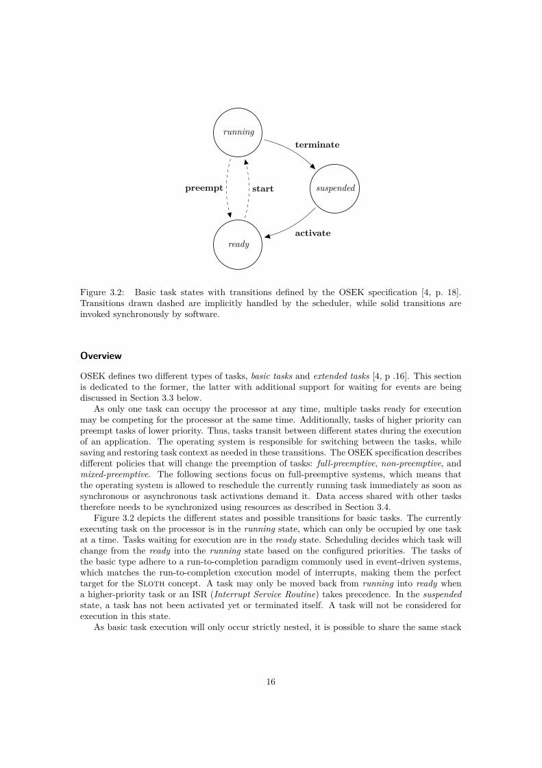
Figure 3.2: Basic task states with transitions defined by the OSEK specification [4, p. 18].Transitions drawn dashed are implicitly handled by the scheduler, while solid transitions areinvoked synchronously by software.
Overview
OSEK defines two different types of tasks, basic tasks and extended tasks [4, p .16]. This sectionis dedicated to the former, the latter with additional support for waiting for events are beingdiscussed in Section 3.3 below.
As only one task can occupy the processor at any time, multiple tasks ready for executionmay be competing for the processor at the same time. Additionally, tasks of higher priority canpreempt tasks of lower priority. Thus, tasks transit between different states during the executionof an application. The operating system is responsible for switching between the tasks, whilesaving and restoring task context as needed in these transitions. The OSEK specification describesdifferent policies that will change the preemption of tasks: full-preemptive, non-preemptive, andmixed-preemptive. The following sections focus on full-preemptive systems, which means thatthe operating system is allowed to reschedule the currently running task immediately as soon assynchronous or asynchronous task activations demand it. Data access shared with other taskstherefore needs to be synchronized using resources as described in Section 3.4.
Figure 3.2 depicts the different states and possible transitions for basic tasks. The currentlyexecuting task on the processor is in the running state, which can only be occupied by one taskat a time. Tasks waiting for execution are in the ready state. Scheduling decides which task willchange from the ready into the running state based on the configured priorities. The tasks ofthe basic type adhere to a run-to-completion paradigm commonly used in event-driven systems,which matches the run-to-completion execution model of interrupts, making them the perfecttarget for the Sloth concept. A task may only be moved back from running into ready whena higher-priority task or an ISR (Interrupt Service Routine) takes precedence. In the suspendedstate, a task has not been activated yet or terminated itself. A task will not be considered forexecution in this state.
As basic task execution will only occur strictly nested, it is possible to share the same stack
16

for all basic tasks in the implementation.
System ServicesWithin an application, a task is declared using a special macro:
TASK(TaskID) { ... }
The TaskID will be used both in the configuration and system services to refer to this particulartask.
The OSEK API models the transitions described above to the corresponding system services:
ActivateTask(TaskType TaskID)
ActivateTask() changes the state of the task corresponding to TaskID from suspended to ready.The operating system is responsible for starting the task as soon as possible according to taskpriorities and scheduling policy. A system may optionally support multiple activations in confor-mance class BCC2 or ECC2. In this case, the activation request will be recorded to be carriedout later if the task is currently not suspended. Without support for multiple activations, a callwill be ignored if the task is not in the suspended state. The configuration defines whether anapplication needs multiple activations or not.
In the Sloth implementation, the ActivateTask() function simply triggers the correspond-ing interrupt source in the ISPR register of the NVIC (see Section 2.2). An interrupt request willbe generated by the hardware if the priority of the requested interrupt is higher than the currentexecution priority. Activating a task with a lower priority will only mark the interrupt source aspending and execution will continue with the calling task.
The implementation has to ensure that task activation happens synchronously. After activa-tion of a higher priority task, preemption has to take place immediately and none of the nextinstructions of the calling task may be executed. As the ISPR register is mapped into the SCS(System Control Space), side-effects of the changes will take place immediately when the writeaccess completes. An additional DSB (Data Synchronization Barrier) will be added to guaran-tee the access has always completed before proceeding. The ARMv7-M Architecture ReferenceManual ([8, p. A3-119]) suggests to use ISB (Instruction Synchronization Barrier) to invoke are-fetch of instructions already in the pipeline. However, the exception entry and return will flushthe pipeline anyway, having the same effect as an ISB instruction here. If the activated task hasa lower priority, no preemption is caused and the execution of the currently running task can justgo on.
TerminateTask(void)
TerminateTask() changes the state of the currently running task to suspended, ending the exe-cution of this task. There is no way to terminate another task; only the currently executing taskcan terminate itself. If this task is activated again later, execution will start at the first instruc-tion. Ending a task without a call to either TerminateTask() or ChainTask() (see below) is notsupported and may result in undefined behavior.
OSEK allows TerminateTask() to be called from a subroutine level of the task. As theCortex-M3 only saves parts of the full register context on the stack automatically (see Section 2.1)and function calls decrease the stack pointer, this situation needs special handling. The solution
17
void prologueTask1(void){
asm volatile ("push {%0, r4-r11, LR}" : : "r" (currentTask));returnSP[1] = currentStackPointer;currentTask = 1;asm volatile ("b functionTask1");
}
Figure 3.3: Implementation of the generated task prologue, here as an example for a task withthe ID 1.
inline void __attribute__((noreturn)) epilogueTask(void){
currentStackPointer = returnSP[currentTask];asm volatile ("pop {%0, r4-r11, LR}" : "=r" (currentTask));asm volatile ("bx LR");
}
Figure 3.4: Implementation of the task epilogue in a basic task system. All tasks use the sameepilogue as the current task ID has to be determined at runtime.
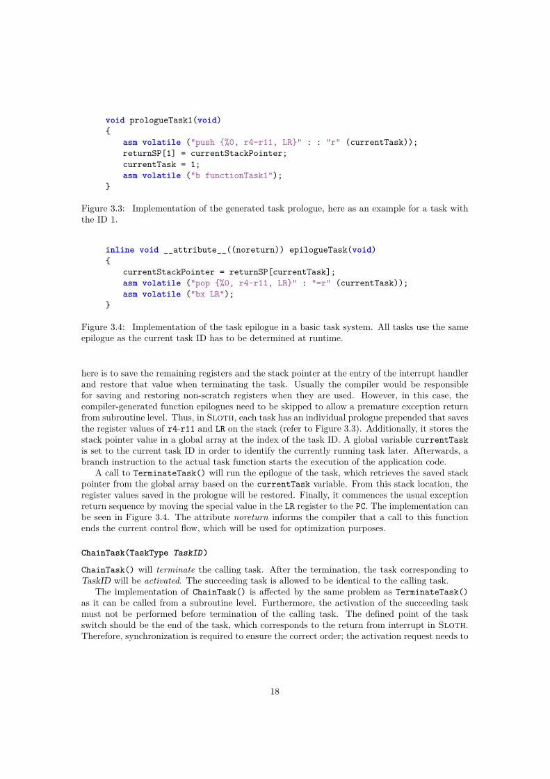
here is to save the remaining registers and the stack pointer at the entry of the interrupt handlerand restore that value when terminating the task. Usually the compiler would be responsiblefor saving and restoring non-scratch registers when they are used. However, in this case, thecompiler-generated function epilogues need to be skipped to allow a premature exception returnfrom subroutine level. Thus, in Sloth, each task has an individual prologue prepended that savesthe register values of r4-r11 and LR on the stack (refer to Figure 3.3). Additionally, it stores thestack pointer value in a global array at the index of the task ID. A global variable currentTaskis set to the current task ID in order to identify the currently running task later. Afterwards, abranch instruction to the actual task function starts the execution of the application code.
A call to TerminateTask() will run the epilogue of the task, which retrieves the saved stackpointer from the global array based on the currentTask variable. From this stack location, theregister values saved in the prologue will be restored. Finally, it commences the usual exceptionreturn sequence by moving the special value in the LR register to the PC. The implementation canbe seen in Figure 3.4. The attribute noreturn informs the compiler that a call to this functionends the current control flow, which will be used for optimization purposes.
ChainTask(TaskType TaskID)
ChainTask() will terminate the calling task. After the termination, the task corresponding toTaskID will be activated. The succeeding task is allowed to be identical to the calling task.
The implementation of ChainTask() is affected by the same problem as TerminateTask()as it can be called from a subroutine level. Furthermore, the activation of the succeeding taskmust not be performed before termination of the calling task. The defined point of the taskswitch should be the end of the task, which corresponds to the return from interrupt in Sloth.Therefore, synchronization is required to ensure the correct order; the activation request needs to
18
inline void ChainTask(TaskType id){
/* set FAULTMASK; raises current execution priority to -1 */asm volatile ("cpsid f");/* activate new task, sets pending bit of corresponding interrupt */ActivateTask(id);/* end this task */epilogueTask();/* implicit reset of FAULTMASK on return from interrupt */
}
Figure 3.5: Implementation of task chaining with use of FAULTMASK.
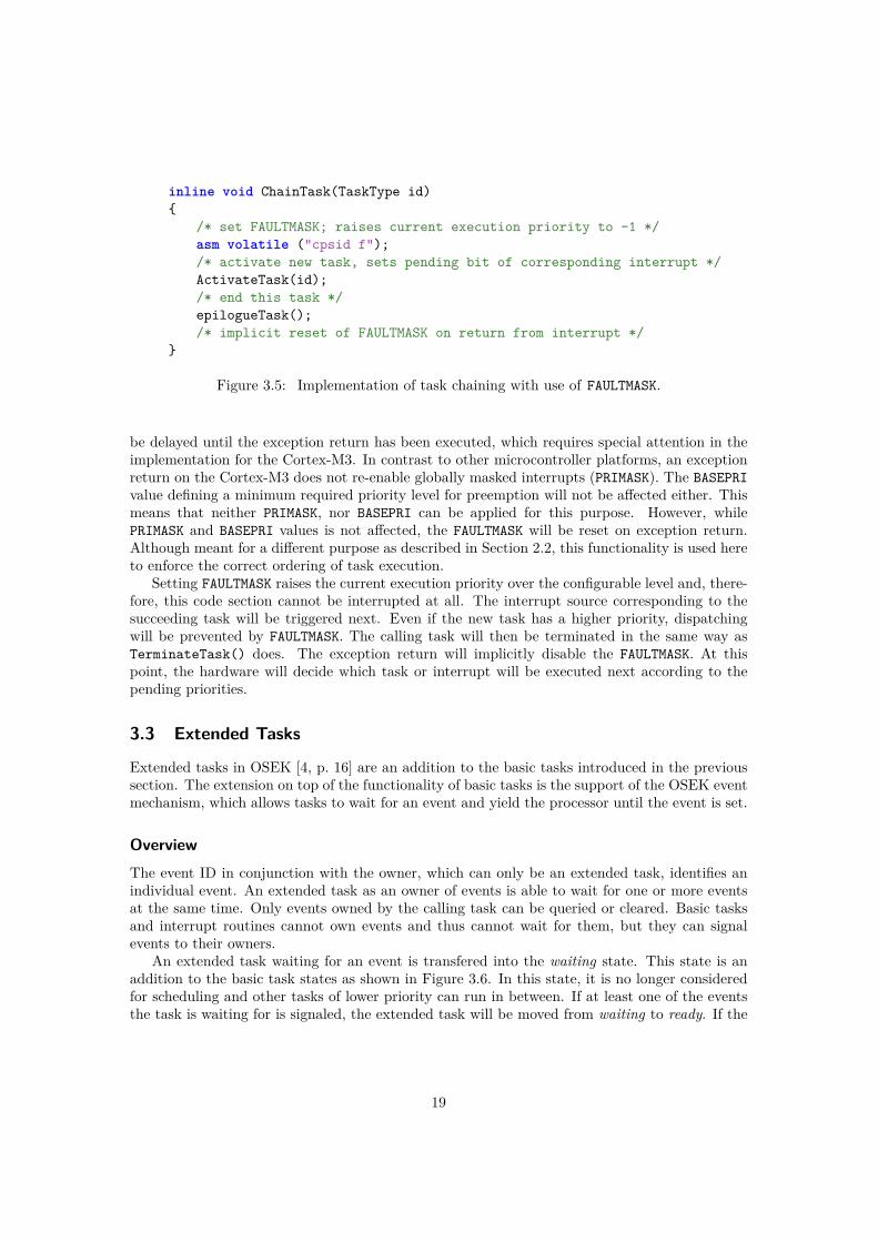
be delayed until the exception return has been executed, which requires special attention in theimplementation for the Cortex-M3. In contrast to other microcontroller platforms, an exceptionreturn on the Cortex-M3 does not re-enable globally masked interrupts (PRIMASK). The BASEPRIvalue defining a minimum required priority level for preemption will not be affected either. Thismeans that neither PRIMASK, nor BASEPRI can be applied for this purpose. However, whilePRIMASK and BASEPRI values is not affected, the FAULTMASK will be reset on exception return.Although meant for a different purpose as described in Section 2.2, this functionality is used hereto enforce the correct ordering of task execution.
Setting FAULTMASK raises the current execution priority over the configurable level and, there-fore, this code section cannot be interrupted at all. The interrupt source corresponding to thesucceeding task will be triggered next. Even if the new task has a higher priority, dispatchingwill be prevented by FAULTMASK. The calling task will then be terminated in the same way asTerminateTask() does. The exception return will implicitly disable the FAULTMASK. At thispoint, the hardware will decide which task or interrupt will be executed next according to thepending priorities.
3.3 Extended Tasks
Extended tasks in OSEK [4, p. 16] are an addition to the basic tasks introduced in the previoussection. The extension on top of the functionality of basic tasks is the support of the OSEK eventmechanism, which allows tasks to wait for an event and yield the processor until the event is set.
OverviewThe event ID in conjunction with the owner, which can only be an extended task, identifies anindividual event. An extended task as an owner of events is able to wait for one or more eventsat the same time. Only events owned by the calling task can be queried or cleared. Basic tasksand interrupt routines cannot own events and thus cannot wait for them, but they can signalevents to their owners.
An extended task waiting for an event is transfered into the waiting state. This state is anaddition to the basic task states as shown in Figure 3.6. In this state, it is no longer consideredfor scheduling and other tasks of lower priority can run in between. If at least one of the eventsthe task is waiting for is signaled, the extended task will be moved from waiting to ready. If the
19

running
suspended
ready
waiting preempt start
terminate
activaterelease
wait
Figure 3.6: Extended task states as an extension to the basic task states as defined by the OSEKspecification [4, p. 17]. This is an extension to the basic task model shown in Figure 3.2 on page16.
event was signaled before the task tried to wait for it, this task remains in the running state.Signaling an event does not activate the task if it is currently in the suspended state. The eventwill be lost in this case.
While basic tasks can share the same stack as they can only preempt each other in a strictlystacked manner, extended tasks can block and wait for an event, during which the previous stateof execution needs to be preserved while other tasks are executed. Therefore, it is necessary toassign separate stacks to each of the extended tasks.
System Services
Sloth uses simple bit fields for the event mask of a task and the events a task is waiting for.The event mask holds the state of the individual events owned by this task; the events a task iswaiting for are those that caused this task to be transfered into the waiting state. This waitingstate is entered and left by blocking and unblocking extended tasks.
GetEvent(TaskType TaskID, EventMaskRefType MaskRef)
GetEvent() copies the state of all events owned by the extended task referenced by TaskID tothe event mask pointed to by MaskRef. This function may be called from any task or interruptservice routine.
In the Sloth implementation, this merely results in a simple check if the corresponding bitsare set in the event mask of the calling task.
20
ClearEvent(EventMaskType Mask)
The service ClearEvent() clears the state of the events listed in Mask in the event mask of thecalling task. Events always have to be cleared manually. This function may only be called fromextended tasks that own the event specified by Mask.
The implementation for clearing an event is a simple bit field operation, removing the bitsfrom the event mask of the calling task.
SetEvent(TaskType TaskID, EventMaskType Mask)
SetEvent() sets the event mask of the task corresponding to TaskID according to Mask. If thespecified task was in the waiting state and waiting for at least one of the events denoted by Mask,it will be transfered into ready state. Other events of this task remain unchanged. This functionmay be called from any task or interrupt service routine.
The implementation of SetEvent() in Sloth will be discussed below in conjunction with theWaitEvent() system service.
WaitEvent(EventMaskType Mask)
The WaitEvent() system service sets the mask of events to be waited for. This function mayonly be called from extended tasks and only events owned by this task may be specified in Mask.
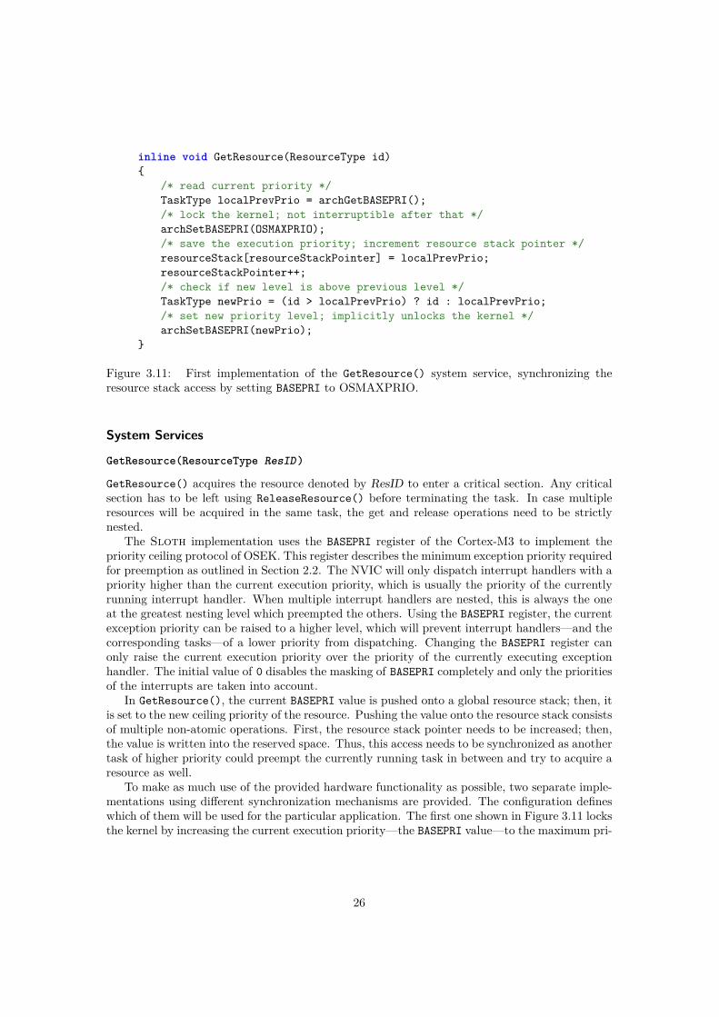
In a system running basic tasks only, all control flows are strictly nested. The possibilityof blocking and unblocking of extended tasks introduces more complexity as all other tasks—even those with a lower priority—can continue their execution while an extended task is in thewaiting state. Interrupt handlers with a run-to-completion execution model are not designed tohandle suspension and resumption; thus, to block a task, it has to be removed from schedulingcompletely. In Sloth, this means that the interrupt controller needs to continue dispatchingother interrupt handlers and their corresponding tasks while ignoring the blocked task. On theARM Cortex-M3, the decision whether a pending interrupt handler can preempt the runningcontrol flow is based on the current execution priority. For this, the NVIC keeps track of allactive exception handlers and takes them into account for calculation of the current executionpriority. The Cortex-M3 will not dispatch any new handler with a lower priority assigned as longas the current execution priority is equal or higher. The priorities assigned to interrupts are usedto determine if a new interrupt handler can be dispatched. However, the priority of a runninginterrupt cannot be lowered by the IPR value in the NVIC as the current execution priorityis only calculated once at the time of dispatching of the interrupt. Therefore, to support thecontinuation model of extended tasks, Sloth has to internally terminate extended tasks whenthey need to block to retain them from scheduling. In order to re-enter the interrupt handler laterat the point of blocking, the full context of the task needs to be stored before it is terminated.
Blocking occurs whenever WaitEvent() is called and the event in question has not been setbefore. As shown in Figure 3.7, after checking the event mask and setting the mask of events tobe waited for, the corresponding interrupt source of the calling task is disabled. This preventsdispatching of this interrupt handler as long as the task is in the waiting state. The interruptis triggered immediately afterwards, so it fires as soon as the interrupt source is enabled again.To unblock a task when SetEvent() signals an event another task is waiting for, the respectiveinterrupt source is enabled again.
To save the full context of the extended task on blocking, a return address is pushed ontothe stack followed by all the register values. This return address points to the instruction rightafter the context saving and termination. This has to be the address right before the compiler-
21

inline void WaitEvent(EventMaskType mask){
/* if at least one event is already set, return immediately */if ((eventMask[currentTask] & mask) != 0) {
return;}
/* no event was set; need to block until an event is signaled */eventsWaitingFor[currentTask] = mask;
/* disable interrupt source for current task and set to pending */archDisableIRQSource(currentTask);archTriggerIRQ(currentTask);
/* retrieve return address from label resumeTask */asm goto (
"adr r0, %l[resumeTask]\n""orr r0, #1\n""push {r0}\n": /* no output */: /* no input */: "r0": resumeTask
);/* store context on stack */asm volatile (
"push {r0-r3, r12}\n""mrs r0, PSR\n""push {r0}\n""push {r4-r11, lr}\n": /* no output */: /* no input */
);contextSP[currentTask] = currentStackPointer;
/* end task, returns from exception */epilogueTask();
resumeTask:; /* dummy to avoid warning "label at end of compound statement" */
}
Figure 3.7: Implementation of the function WaitEvent()
22

Enter Extended Task Prologue
Push context onto stack
getType(currentTask) == basic? interruptedBasicTaskSP := SP
currentTask := N
hasSeenCPU[currentTask]?
Restore context fromcontextSP[currentTask]
Continue at resumeTask label
hasSeenCPU[currentTask] := true
Initialize Stack Pointer
Jump to functionTaskN
1
2 2a
3
4
5a
6a
5b
6b
7b
no
yes
yes
no
Figure 3.8: State diagram of the prologue for extended task N. As each prologue is generatedindividually, the number N will be replaced for the specific task.
generated function epilogue to restore any non-scratch registers used in the implementing func-tion.
The Sloth implementation uses the relatively new asm goto statement introduced withversion 4.5 of GCC (GNU Compiler Collection) [12, 13]. This statement is an extension tothe usual asm statement; it allows to retrieve the address of a C label and to be used in jumpstatements. This makes it possible to inline the implementing function. Using an asm label wouldhave prevented inlining as the asm label can only be accessed in the global scope whereas here theaddress needs to be calculated each time the function will be inlined. The last bit of the addresshas to be set to 1 to indicate that the target location is assembled in the Thumb instruction set.
The current task context is pushed onto the stack and the stack pointer is saved to a globalarray indicating where the context can be found for the restore operation. Afterwards, the taskis terminated using the epilogue for task termination which is described in detail in Section 3.2above.
A matching prologue exists for extended tasks in the same way as for basic tasks, which isdepicted in Figure 3.8. After saving the context of the interrupted task and setting the currenttask ID in steps 1–3, this prologue of an extended task additionally needs to check whetherit has been activated or resumes from waiting state in step 4. If it has run before, the savedcontext needs to be restored by popping the values from the stack location back into the registers(step 5a). The return address pushed before will be written to the program counter in step 6a,completing the re-entry of the handler at the position after it was blocked. Otherwise, if the taskdid not run before, it is marked as running in step 5b. After initialization of the stack pointer instep 6b, the prologue jumps directly to the user task function in the last step 7b.
Stack switches are necessary in the prologue not only for extended tasks, but for basic tasks
23
as well. All basic tasks share the same stack as their invocation happens strictly nested, whereaseach extended task uses its own stack. Extended tasks load their predefined stack pointer inthe prologue in the initialization or implicitly set them by a restore of the saved context whenreturning from waiting state. A basic task preempting an extended task needs to return to theshared stack used by all basic tasks. Therefore, if the interrupted task was of the basic type,the prologue of an extended task saves the stack pointer of the basic task stack after saving itscontext. The prologue of the basic task will load this value and continue its operation on thebasic task stack. When a basic task preempts another basic task, no action needs to be taken asthey share the same stack.
3.4 Resource Management
OverviewThe resource management in OSEK is responsible for coordination of concurrent accesses toshared resources [4, p. 29]. These resources could represent system components, memory ranges,or hardware peripherals. The operating system ensures that
• only one task can occupy a resource at a time,
• no deadlocks occur by use of resources, and
• priority inversion cannot occur.
To achieve these goals, OSEK prescribes a special kind of priority ceiling protocol. Resourcesare available in all OSEK conformance classes.
OSEK Priority Ceiling ProtocolThe most common problems of synchronization methods like semaphores or mutexes are priorityinversion and deadlocks. When using mutexes for synchronization, a task has to be blocked whenthe attempt to acquire a mutex was not successful as it was already occupied. Using a spin-lockis not possible in an event-driven uniprocessor system as taking it would immediately lead to anobvious deadlock. Additionally, priority inversion can occur when lower-priority tasks delay theexecution of a higher priority task.
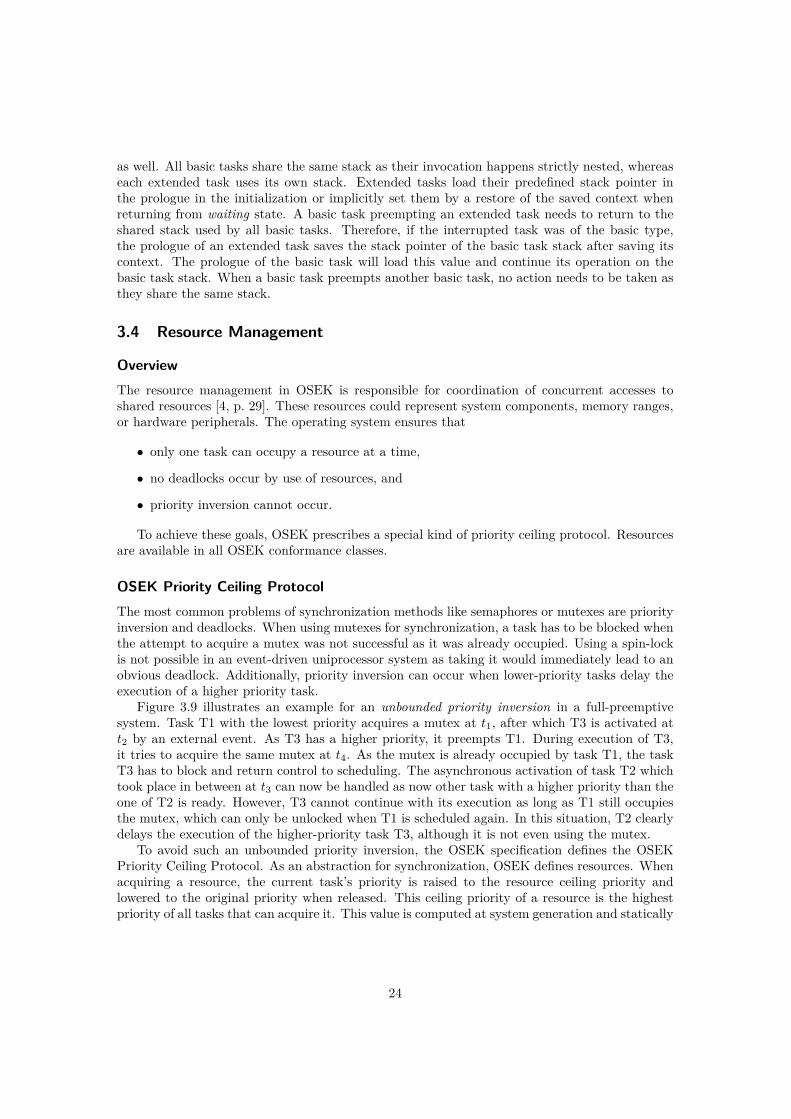
Figure 3.9 illustrates an example for an unbounded priority inversion in a full-preemptivesystem. Task T1 with the lowest priority acquires a mutex at t1, after which T3 is activated att2 by an external event. As T3 has a higher priority, it preempts T1. During execution of T3,it tries to acquire the same mutex at t4. As the mutex is already occupied by task T1, the taskT3 has to block and return control to scheduling. The asynchronous activation of task T2 whichtook place in between at t3 can now be handled as now other task with a higher priority than theone of T2 is ready. However, T3 cannot continue with its execution as long as T1 still occupiesthe mutex, which can only be unlocked when T1 is scheduled again. In this situation, T2 clearlydelays the execution of the higher-priority task T3, although it is not even using the mutex.
To avoid such an unbounded priority inversion, the OSEK specification defines the OSEKPriority Ceiling Protocol. As an abstraction for synchronization, OSEK defines resources. Whenacquiring a resource, the current task’s priority is raised to the resource ceiling priority andlowered to the original priority when released. This ceiling priority of a resource is the highestpriority of all tasks that can acquire it. This value is computed at system generation and statically
24
Execution Priority
t
1
2
3
t1 t2 t3 t4 t5 t6 t7 t8
Task T1lock() E Act(T3)
Task T3 EAct(T2)
lock()
Task T2 Term()
Task T1unlock()
Task T3 unlock() Term()
Task T1
Figure 3.9: An example for an unbounded priority inversion problem using mutexes. Theexecution of the high-priority task T3 is delayed by task T2, although it has a lower priority.
Execution Priority
t
1
2
3
t1 t2 t3 t4 t5 t6 t7 t8
Task T1lock()
Task T1 EAct(T3)
E
Act(T2)
unlock()
Task T3 lock() unlock() Term()
Task T2 Term()
Task T1
Figure 3.10: The solution to the unbounded priority inversion problem presented in Figure 3.9using the OSEK priority ceiling protocol.
assigned to each resource. Tasks using the same resource therefore have a priority lower or equalto the resource’s ceiling priority. Therefore, the ceiling priority required for a specific resource isthe highest priority of all tasks accessing this resource.
The solution applied to the unbounded priority inversion problem using the OSEK priorityceiling protocol is shown in Figure 3.10. The priority of task T1 is raised to the ceiling prioritywhen acquiring the resource at t1 and falls down to the original value when releasing the resourcein t3. But at this point, the priority is not actually lowered again, as task T3 was marked pendingby an external event at t2 and is dispatched as soon as the execution priority allows at t3. Hence,task T3 is only delayed for the time T1 occupies the resource in the critical section between t1and t3. As no other task such as task T2 is able to run in between, the execution of T3 is notdelayed any further.
This priority ceiling protocol ensures that no task can be preempted by another task accessingthe same resource while the resource is occupied. Although this protocol still allows tasks witha priority higher than the one of the acquiring task, but lower or equal to the ceiling priority tobe delayed, the duration of the delay is always limited to the time a resource is occupied by alower-priority task.
25
inline void GetResource(ResourceType id){
/* read current priority */TaskType localPrevPrio = archGetBASEPRI();/* lock the kernel; not interruptible after that */archSetBASEPRI(OSMAXPRIO);/* save the execution priority; increment resource stack pointer */resourceStack[resourceStackPointer] = localPrevPrio;resourceStackPointer++;/* check if new level is above previous level */TaskType newPrio = (id > localPrevPrio) ? id : localPrevPrio;/* set new priority level; implicitly unlocks the kernel */archSetBASEPRI(newPrio);
}
Figure 3.11: First implementation of the GetResource() system service, synchronizing theresource stack access by setting BASEPRI to OSMAXPRIO.
System Services
GetResource(ResourceType ResID)
GetResource() acquires the resource denoted by ResID to enter a critical section. Any criticalsection has to be left using ReleaseResource() before terminating the task. In case multipleresources will be acquired in the same task, the get and release operations need to be strictlynested.
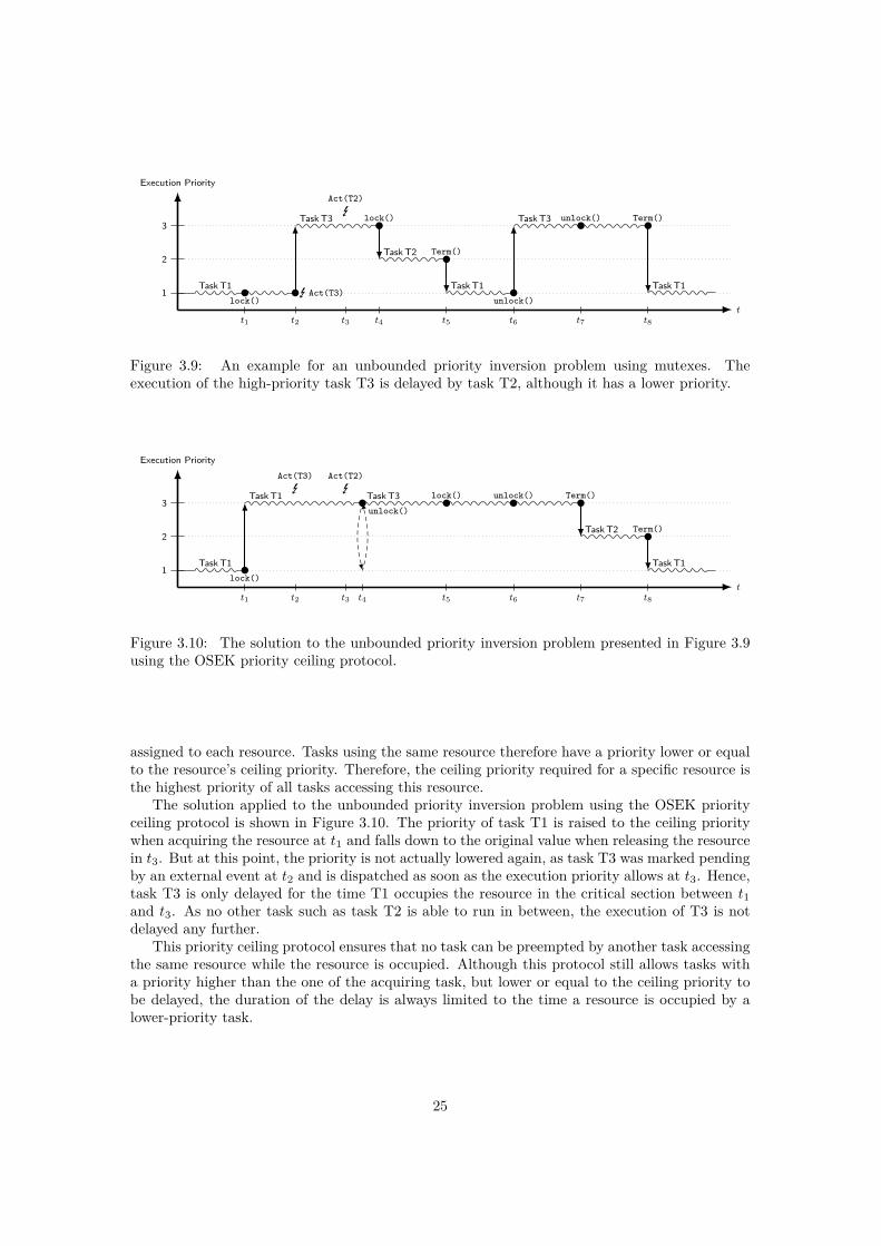
The Sloth implementation uses the BASEPRI register of the Cortex-M3 to implement thepriority ceiling protocol of OSEK. This register describes the minimum exception priority requiredfor preemption as outlined in Section 2.2. The NVIC will only dispatch interrupt handlers with apriority higher than the current execution priority, which is usually the priority of the currentlyrunning interrupt handler. When multiple interrupt handlers are nested, this is always the oneat the greatest nesting level which preempted the others. Using the BASEPRI register, the currentexception priority can be raised to a higher level, which will prevent interrupt handlers—and thecorresponding tasks—of a lower priority from dispatching. Changing the BASEPRI register canonly raise the current execution priority over the priority of the currently executing exceptionhandler. The initial value of 0 disables the masking of BASEPRI completely and only the prioritiesof the interrupts are taken into account.
In GetResource(), the current BASEPRI value is pushed onto a global resource stack; then, itis set to the new ceiling priority of the resource. Pushing the value onto the resource stack consistsof multiple non-atomic operations. First, the resource stack pointer needs to be increased; then,the value is written into the reserved space. Thus, this access needs to be synchronized as anothertask of higher priority could preempt the currently running task in between and try to acquire aresource as well.
To make as much use of the provided hardware functionality as possible, two separate imple-mentations using different synchronization mechanisms are provided. The configuration defineswhich of them will be used for the particular application. The first one shown in Figure 3.11 locksthe kernel by increasing the current execution priority—the BASEPRI value—to the maximum pri-
26

inline void GetResource(ResourceType id){
/* read current priority */TaskType localPrevPrio = archGetBASEPRI();/* lock the kernel; not interruptible after that */archDisableIRQs();/* save the execution priority; increment resource stack pointer */resourceStack[resourceStackPointer] = localPrevPrio;resourceStackPointer++;/* set new priority level if new value is greater */archSetBASEPRI_MAX(id);/* unlock the kernel */archEnableIRQs();
}
Figure 3.12: Second implementation of the GetResource() system service, synchronizing theresource stack access by disabling interrupts.
ority of all tasks and category-2 ISRs. The access to the BASEPRI register is encapsulated intowrapper functions archGetBASEPRI and archSetBASEPRI. The actual value is calculated duringsystem generation as OSMAXPRIO.
In Sloth, tasks and category-2 ISRs, which are allowed to access system services, are notdistinct as in traditional OSEK conforming implementations since they share the same priorityspace. ISRs of category 1, which cannot use system calls, will have priorities assigned higher thanthose of tasks and category-2 ISRs. Thus, raising the current execution priority to OSMAXPRIOwill only lead to suspension of tasks and category-2 ISRs, while ISRs of category 1 with the higherpriority can still be handled as usual.The second implementation shown in Figure 3.12 utilizes the hardware by using BASEPRI_MAXto update the current execution priority. The BASEPRI_MAX register specification actually refersto the same register as BASEPRI, but has a conditional write. When writing a new value toBASEPRI_MAX, the hardware will compare it with the current value and applies the change onlyif the new value is greater than the current value. Otherwise, the write is ignored. This has theadvantage that it is not necessary to read the value, compare it, and then write a new value asit would be done in software. Thus, as reading the value can be omitted, using BASEPRI_MAXshould result in better performance for GetResource().
However, the stack access still needs to be synchronized. To take advantage of BASEPRI_MAX,this cannot be done by raising the BASEPRI for locking purposes already. Therefore it is necessaryto lock the kernel by disabling interrupts completely using PRIMASK, which is modified using thehelper functions archDisableIRQs and archEnableIRQs. The drawback is that category-1 ISRswould be blocked as well, but only for the bounded time until the GetResource() system serviceis completed, which only takes a couple of cycles.
ReleaseResource(ResourceType ResID)
ReleaseResource() releases the resource denoted by ResID by restoring the previous value ofBASEPRI from the global resource stack. The implementation is shown in Figure 3.13 and un-
27

inline void ReleaseResource(ResourceType id){
/* lock the kernel; not interruptible after that */archSetBASEPRI(OSMAXPRIO);/* decrement resource stack pointer */resourceStackPointer--;/* restore the previous execution priority; implicitly unlocks the kernel */archSetBASEPRI(resourceStack[resourceStackPointer]);
}
Figure 3.13: Implementation of the ReleaseResource() system service.
like above for GetResource(), no alternative implementation is possible. ReleaseResource()is always synchronized using OSMAXPRIO with an implicit unlock by restoring the previ-ous execution priority level. This leaves the critical section enclosed by GetResource() andReleaseResource().
RES_SCHEDULER
In an OSEK system, a task can protect itself against preemption by other tasks by acquiring thespecial resource RES_SCHEDULER(). This resource is automatically generated and accessible fromall tasks. It is implemented as a normal resource following the priority ceiling protocol with aresource priority that is the same priority as the highest priority used for any task.
3.5 Alarms
OverviewAlarms in the OSEK operating system [4, p. 36] are used to run actions in either periodic orone-shot modes. They can be configured statically to activate specific tasks when a timer expires.
System Services
SetRelAlarm(AlarmType AlarmID, TickType increment, TickType cycle)
After increment ticks have elapsed, the assigned task will be activated. The cycle count can beused to set up periodic alarms, which will be set up again every time they expire. After the firstinvocation, the alarm will fire every cycle ticks. A value of 0 sets up a one-shot alarm.
The implementation uses the three timer counters included on the Atmel SAM3U board [10,p. 755]. These are organized around 16-bit counters driven by either the main clock modified bya scale factor or a slow clock running at constant 32,768 Hz. Each of them can be programmedto generate an individual interrupt when a specific counter value is reached. Depending on theapplication, the timer counters need to be configured to the correct clock sources. Using a differentclock speed has an impact on the maximum ticks that can be specified for a SetRelAlarm() call.A task supposed to be activated by an alarm is mapped directly to the interrupt number of thecorresponding timer counter in the configuration. For such tasks, a slightly different prologuewill be generated as the external interrupt of the timer counter needs to be acknowledged. This
28
only adds one instruction and still works when activated manually using ActivateTask(). TheSetRelAlarm() system service merely computes and sets the compare value for the correspondingtimer counter derived from AlarmID and starts the timer. The counting will be done by thehardware until expiry of the timer activates the task by triggering its interrupt source.
The ARMv7-M architecture also provides a system timer called SysTick. This timer is capableof generating an interrupt after a specific tick count, but is limited to only one entry in the vectortable. Thus, an implementation with support for multiple alarms would require a dispatcher insoftware to activate the corresponding tasks. To support this, additional data about the alarmswould need to be kept in memory. Although using the SysTick would be more portable acrossdifferent Cortex-M3 hardware, the timer counters as provided by the SAM3U board match theSloth concept better.
3.6 Summary
The Sloth implementation detailed in this chapter implements OSEK system services for taskmanagement of basic and extended tasks, resource management, and alarms. Both task andresource management utilize the NVIC as part of the ARM Cortex-M3 for the implementationof interrupt-driven scheduling. The implementation of alarms uses the timer counters providedon the Atmel SAM3U board used for this thesis which are able to trigger interrupt sources aftera given amount of time has elapsed.
29

Chapter 4
Evaluation
The Sloth implementation was evaluated on an Atmel SAM3U4E evaluation kit, which includesa Cortex-M3 revision 2.0. The board was configured to run at 48 MHz, which is the defaultclock speed in the startup code provided by Atmel. Measurements were taken in frequency-independent clock cycles to analyze the run time of selected scenarios in a preemptive operatingsystem conforming to OSEK classes BCC1 and ECC1 in Section 4.1.
Additionally, due to the variability in hardware platforms, several aspects of the Slothimplementation for the ARM Cortex-M3 use a different approach as the reference implementationon the Infineon TriCore. Section 4.2 analyzes the differences in the systems and their implicationon the system services.
Finally, the implemented feature set of OSEK is discussed in Section 4.3, explaining thecurrent limitations of the system.
4.1 Performance Evaluation
To confirm the positive effects of the Sloth concept on the non-functional properties of an op-erating system, the performance of the Sloth implementation was compared to another OSEK-conforming implementation. For this purpose, Arctic Core was chosen, which is a multi-platformoperating system developed as an open source project [14]. It implements the AUTOSAR specifi-cation, which is a superset of the OSEK specification using the same interface for system services.Although Arctic Core supports the ARM Cortex-M3 platform on several boards already, somesmall changes to the build system, startup code, and linker scripts against version 2.9.1 werenecessary to add support for the Atmel SAM3U board used in this thesis.
4.1.1 Measurement Setup
The ARMv7-M architecture defines several components for debugging purposes. A debugger canbe attached using a normal JTAG connector, which can read arbitrary registers and memoryaddresses, set breakpoints, and step through the code executed on the device. Additionally,the Instrumentation Trace Macrocell (ITM) and the optional Embedded Trace Macrocell (ETM)can generate timestamps and instruction traces, which can be read out using the Serial WireDebug protocol. The Atmel SAM3U4E used for this thesis does not provide the ETM and only aJTAG adapter was available, which is not capable of reading the ITM data from the debug port.
31
Thus, a different approach using the Data Watchpoint and Trace unit (DWT) was used to takemeasurements of the implemented software.
The DWT provides, among other registers, a memory-mapped 32-bit cycle count registerCYCCNT, which is incremented each clock cycle. This can be used to obtain the amount of clockcycles a specific code section needs for execution. After enabling the cycle counter in the DWT,the CYCCNT register can be read any time to get the current clock cycle count since the counterwas reset.A simple measurement using this approach would look like this:
uint32_t value;DWT->CYCCNT = 0;/* ... code to be measured ... */value = DWT->CYCCNT;
As the DWT uses memory-mapped registers for control, the compiler-generated assembly codeaccessing CYCCNT needs to load its address first. For a small piece of code, this will be held in aregister during execution of the examined code. However, for a larger section, the value will becalculated and loaded again. Depending on the surrounding code, an optimizing compiler mighteven try to merge the calculation with other statements, moving statements out of the examinedsection. To avoid falsified results or unsteady overhead to be added to the measured cycles, theregister accesses were wrapped into small helper functions.
uint32_t value;sam3uMeasureStart();/* ... code to be measured ... */value = sam3uMeasureStop();
This way, only two additional branch statements to sam3uMeasureStart and sam3uMeasureStopwill be inserted in the code, respectively. Attributes advising the compiler not to inline thesestart/stop functions to ensure branch statements are also included. In the stop function, themeasurement code automatically subtracts the overhead added by these calls, which is determinedin an initial measurement at the beginning of the test program.
The execution time of a code section on the Cortex-M3 is usually predictable as long asno branch instructions are hit in the instruction stream and no interrupts occur in between.However, fetching instructions from the embedded flash controller may be delayed dependingon the address and wait states applied. For example, a halfword-aligned 32-bit instruction willrequire a second fetch as all instruction fetches are word-wide. That is why the compiler wasinstructed to align the 32-bit branch instruction to the start function to a word boundary, which ismeant to ensure the overhead introduced by the measurements is constant. Of course, dependingon the measured code, the stop function might still hit a halfword boundary, which might leadto a single cycle added to the measurement. However, this is inherent to the measured code andcannot be avoided.
The flash controller on the SAM3U4E optimizes sequential read accesses using buffers, addingtwo wait states for the first instruction of a block by default. To simulate an environment as itwould be used in real applications, this was not changed. Additionally, at each branch instruction,the 3-stage pipeline of the Cortex-M3 might need to be flushed if the branch prediction guessedwrong. Therefore, the initial measurement to calculate this overhead is performed with 8 NOPinstructions. This number was chosen as the encoding of 16-bit NOP instructions is a multipleof four to mitigate the effects of misaligned instructions and is long enough to fill the pipeline ofthe Cortex-M3.
32
The measured values also need to be retrieved from the board. The host computer wasconnected over a serial interface using the Universal Asynchronous Receiver/Transmitter (UART)on the SAM3U hardware. The start/stop functions mentioned above were extended to transmitthe measurement value right after it has been obtained to the host computer, where furtherprocessing may take place. All measurements were repeated multiple times, but as execution onthe ARM Cortex-M3 is fully deterministic, this leads to zero deviation between all runs.
4.1.2 System ConfigurationAs both Sloth and Arctic Core support the OSEK system services, the same test applicationswere used on both systems. Both systems were compiled using the GNU Compiler Collectionwith the optimization level -O3 and assertions disabled. The configuration was almost the samefor both implementations. Whereas Sloth uses a shared stack for basic tasks, the Arctic Coreimplementation always uses distinct stacks for each of the tasks. This will have a slightly adverseinfluence on the performance of task switches in the Arctic Core system as they always involveswitching stacks, although this would not be necessary in a BCC1 system with only basic tasksinvolved. Additionally, advanced features of Arctic Core were disabled by using the AUTOSARscalability class 1, which is backwards compatible to OSEK.
For the Sloth implementation, an additional optimization regarding task switches was eval-uated. Most system services need to know which task is currently active as they use this taskID as an offset in an array or for similar actions. Usually, this would involve loading the infor-mation from a memory location, which requires multiple bus accesses to load the address firstand then the actual value. Thus, these accesses can be optimized by keeping the current taskID in a general-purpose register instead of a memory location. As all registers are normallyunder control of the compiler, a register has to be reserved globally and may not be used in anycompiler-generated code. GCC allows to mark a register as fixed with the option -ffixed-reg ,which removes it from the register allocator and generated code will never refer to it. As onlylow registers r0–r7 can be addressed by all 16-bit instructions in the Thumb instruction set andusing one of these would reduce the available registers for most instructions, the high register r11is chosen for this purpose. The downside of this approach is that all code has to be compiled withthe appropriate compiler flag and, thus, linking against binary-distributed libraries is impossible.
Thus, the test cases were evaluated on two separate configurations for Sloth, where onestores the current task ID in a register and the other one uses conventional memory, and as thethird competitor, the Arctic Core implementation. On all three systems, multiple scenarios wereevaluated to show the performance of the implementation on task switching, synchronizationwith resources, and handling of events.
4.1.3 Test ScenariosTo cover as many scenarios as possible in the evaluation, three separate test applications wereprepared for measurements. The first one uses basic tasks only, where the performance of taskswitches and resources using the OSEK priority ceiling protocol can be observed. The secondone uses extended tasks only, where task blocking and the effects of the additionally requiredstack switches on the performance can be inspected. Finally, the last test application implementsboth basic and extended tasks, which allows to analyze the impact of extended tasks in the samesystem as basic tasks on their task switching performance and the scalability of the implementedsystem services. The selected test cases include all task-switching-related system services thatstand to benefit from use of the hardware in the Sloth implementation.
33

Test Case Sloth ArcCore Speed-Upregister memory
A1 ActivateTask without dispatch 9 9 233 25.9A2 ActivateTask with dispatch 40 56 507 12.7A3 TerminateTask with dispatch 24 33 310 12.9A4 ChainTask with dispatch 61 84 471 7.7
A5 GetResource{a) synchr. using OSMAXPRIOb) synchr. using PRIMASK
31 32 126 4.121 22 6.0
A6 ReleaseResource without dispatch 29 29 185 6.4A7 ReleaseResource with dispatch 63 80 461 7.3
Table 4.1: Performance evaluation of task switching and resources in a system with basic tasksonly. The values specify the measured execution time in number of clock cycles. The speed-upis the comparison of the Sloth register variant with Arctic Core.
The latencies of all system services are measured from the point before the invoking statementuntil the action is completed. For instance, a preempting task activation is measured from thepoint before ActivateTask()() to the first application instruction in the activated task func-tion, and a task termination is measured from the point before TerminateTask()() to the nextinstruction in the following task. If no preemption or task dispatching occurs, the measurementis ended at the next instruction right after the statement invoking the system service.
4.1.4 Basic-Task SystemThe results for task switching in a system with basic tasks only is presented in Table 4.1 as acomparison between the two Sloth configurations—with the current task ID in a register or inmemory—and the Arctic Core system.
Sloth-Internal Evaluation Results
The numbers show clearly how Sloth can benefit from the optimization of keeping the currenttask ID in a general-purpose register for system services operating with this number. Althoughtest case A1 is not influenced at all as activating a task without preemption does not involve thecurrent task ID, test case A2 runs faster since the context saving in the prologue of the dispatchedtask can take advantage of the optimization. By using a register, the current task ID is storedaltogether with other registers, whereas by using a memory location, a separate load and storesequence is required. Similar improvements can be observed in both task termination and taskchaining in test cases A3 and A4. Overall, the register variant has a maximum speedup of 1.4compared to using a memory location.
For resource acquisition in test case A5, the performance of the two implemented methods forsynchronization as described in Section 3.4 were compared. Implementation a) raises the currentexecution priority in BASEPRI to OSMAXPRIO in order to synchronize accesses to the resourcestack, whereas implementation b) takes advantage of the hardware by using BASEPRI_MAX forsetting the new execution priority, which renders reading and comparing the value in softwareunnecessary. Therefore it has to implement a different way for synchronization by disabling inter-rupts completely using PRIMASK. The results show that both implementations are not influenced
34
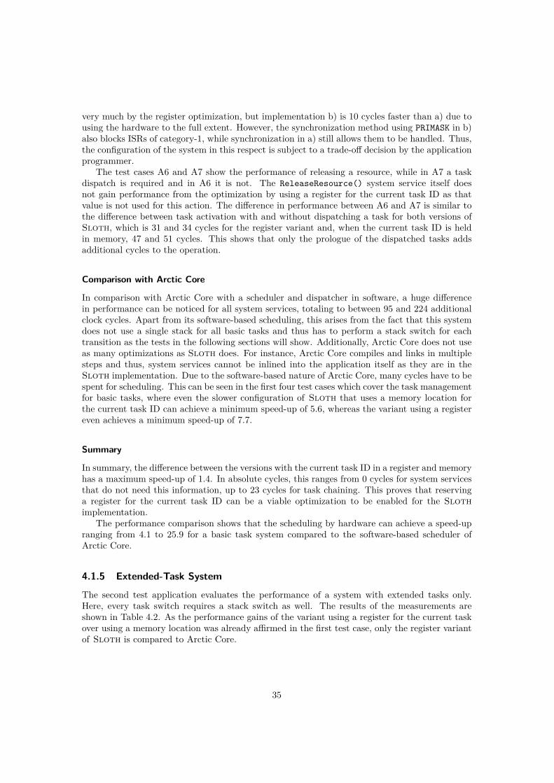
very much by the register optimization, but implementation b) is 10 cycles faster than a) due tousing the hardware to the full extent. However, the synchronization method using PRIMASK in b)also blocks ISRs of category-1, while synchronization in a) still allows them to be handled. Thus,the configuration of the system in this respect is subject to a trade-off decision by the applicationprogrammer.
The test cases A6 and A7 show the performance of releasing a resource, while in A7 a taskdispatch is required and in A6 it is not. The ReleaseResource() system service itself doesnot gain performance from the optimization by using a register for the current task ID as thatvalue is not used for this action. The difference in performance between A6 and A7 is similar tothe difference between task activation with and without dispatching a task for both versions ofSloth, which is 31 and 34 cycles for the register variant and, when the current task ID is heldin memory, 47 and 51 cycles. This shows that only the prologue of the dispatched tasks addsadditional cycles to the operation.
Comparison with Arctic Core
In comparison with Arctic Core with a scheduler and dispatcher in software, a huge differencein performance can be noticed for all system services, totaling to between 95 and 224 additionalclock cycles. Apart from its software-based scheduling, this arises from the fact that this systemdoes not use a single stack for all basic tasks and thus has to perform a stack switch for eachtransition as the tests in the following sections will show. Additionally, Arctic Core does not useas many optimizations as Sloth does. For instance, Arctic Core compiles and links in multiplesteps and thus, system services cannot be inlined into the application itself as they are in theSloth implementation. Due to the software-based nature of Arctic Core, many cycles have to bespent for scheduling. This can be seen in the first four test cases which cover the task managementfor basic tasks, where even the slower configuration of Sloth that uses a memory location forthe current task ID can achieve a minimum speed-up of 5.6, whereas the variant using a registereven achieves a minimum speed-up of 7.7.
Summary
In summary, the difference between the versions with the current task ID in a register and memoryhas a maximum speed-up of 1.4. In absolute cycles, this ranges from 0 cycles for system servicesthat do not need this information, up to 23 cycles for task chaining. This proves that reservinga register for the current task ID can be a viable optimization to be enabled for the Slothimplementation.
The performance comparison shows that the scheduling by hardware can achieve a speed-upranging from 4.1 to 25.9 for a basic task system compared to the software-based scheduler ofArctic Core.
4.1.5 Extended-Task System
The second test application evaluates the performance of a system with extended tasks only.Here, every task switch requires a stack switch as well. The results of the measurements areshown in Table 4.2. As the performance gains of the variant using a register for the current taskover using a memory location was already affirmed in the first test case, only the register variantof Sloth is compared to Arctic Core.
35

Test Case Sloth ArcCore Speed-UpB1 ActivateTask (extended) with dispatch 60 505 8.4B2 WaitEvent with dispatch 96 325 3.3B3 SetEvent with dispatch 87 407 4.7B4 ClearEvent 9 48 5.3B5 TerminateTask (extended) with dispatch 30 312 10.4B6 ChainTask (extended) with dispatch (same task) 94 235 2.5
Table 4.2: Performance evaluation of task switching and blocking in a system with extendedtasks only, which requires stack switches for all system services except B4. The values specifythe measured execution time in number of clock cycles.
Sloth-Internal Evaluation Results
Although the blocking and unblocking of tasks does not fit to the run-to-completion model ofinterrupt handlers, the Sloth implementation achieves respectable performance. Task switchesbetween extended tasks in B1 and B5 take a little bit longer than basic task switches in A2and A3 with a difference ranging between 6–20 cycles compared to the register variant. Thisis because task switches for extended tasks involve stack switches and more conditional checks.The task termination in B5 requires less additional cycles with only 6 cycles compared to theregister variant in A3 as the code path is very similar as the next test application will show inmore detail. The additional cycles required for task activation with dispatch are added by theextended task prologue as it has to do stack switches and needs to check whether it resumes fromwaiting for an event or was dispatched without prior context.
The ClearEvent() system service in B4 takes the fewest time with 9 cycles as it only operateson a bit mask. The task blocking implemented in WaitEvent() as tested in B2 involves savingthe full context state of the task in order to block the task and remove it from scheduling. Thissystem service—including a following dispatch—takes 96 cycles in the Sloth implementation.The task unblocking caused by SetEvent(), which allows a blocked extended task to continue itsoperation, takes 87 cycles, which includes the extended task prologue which restores the previouscontext. Therefore, with 27 cycles more, this takes significantly longer than a task activation of60 cycles in B1, where the prologue can directly jump to the user task function. Test case B6of extended task chaining takes 33 cycles longer than basic task chaining in A4 which alreadyincludes the additional 6 cycles for task termination and additional 20 cycles for the extendedtask activation.
Comparison with Arctic Core
Again, all system services have an performance improvement over Arctic Core, while the speed-up ranging from 2.5 to 10.4 is not as high as it is for a basic task system. The extended taskactivation of Arctic Core in B1 is very similar to the basic task activation in A2 with a difference ofonly 2 cycles, which could also be caused by unaligned instruction accesses in the measurement asoutlined in Section 4.1.1. The same is observed for task termination in B5 and A3, which also onlydiffers in 2 cycles. However, this suggests that Arctic Core does not handle basic and extendedtasks differently and especially requires the same overhead for scheduling and dispatching insoftware for both of them.
The lowest speed-up value was measured for task chaining in B6, which, as said, differences
36

Test Case Task Type Transition Stack Switch Sloth ArcCore Speed-UpC1 ActivateTask Basic → Basic no 42 505 12.0C2 ActivateTask Basic → Extended yes 65 525 8.0C3 ActivateTask Extended → Basic yes 47 525 11.2C4 WaitEvent Extended → Basic yes 112 357 3.2C5 SetEvent Basic → Extended yes 92 407 4.4C6 TerminateTask Basic → Basic no 33 313 9.5C7 TerminateTask Extended → Basic yes 33 312 9.5C8 TerminateTask Extended → Extended yes (dispatch new task) 83 346 4.2C9 ChainTask Basic → Basic no (dispatch same task) 74 233 3.1
Table 4.3: Performance evaluation of task switching and blocking in a mixed task system withboth basic and extended tasks, which requires stack switches for transition involving extendedtasks. The values specify the measured execution time in number of clock cycles.
from the basic task chaining in A4 as the former chains the same task again, where Arctic Coreachieves a faster operation for B6 than for A4. Arctic Core probably optimizes the special case ofchaining the same task, which does not need to switch stacks as it is safe to assume the currentlyterminated task will again be the task with the highest priority. Although Sloth does not applyany optimization for this case, it still outperforms the software-based scheduler with a speed-upof 2.5.
Summary
In the performance comparison with Arctic Core, the Sloth implementation achieves a speed-upranging from 2.5 up to 10.4 for an extended-task system. This is not as high as for the first testapplication which only involves basic tasks. However, extended tasks do not match the run-to-completion model of interrupt handlers and this second test application shows that the Slothimplementation of task blocking again performs faster than a software-based scheduler.
4.1.6 Mixed Task SystemThe third test application examines the performance in a system with both basic and extendedtasks; the results are shown in Table 4.3. The comparison is between Sloth, configured to use aregister for the current task ID, and the Arctic Core implementation. The task transitions denotewhich task called the system service and which task is chosen to run next after the schedulerdecision. The table also indicates required stack switches for transitions involving extended tasks.
Sloth-Internal Evaluation Results
In a mixed task system using the Sloth kernel, also the basic task switches are affected by asmall performance penalty (for instance, 2–5 cycles in C1 and C2 when compared to A2 and B1),as checks whether the preempted task was extended—leading to a stack switch—are required.Similarly, task termination and task chaining execute additional instructions as they need todistinguish whether the calling task is basic or extended by checking the calling task ID.
Basic task activation from within an extended task in C3 only has a very small overhead of 5cycles for the stack switch compared to the basic task activation from within a basic task in C1.
37

Task termination in test cases C6 and C7 has the same timing of 33 cycles as both test cases takethe same code path in Sloth. At preemption, the context is always stored on the current stackand the stack pointer is saved to allow an exit of the task from subroutine level. Thus, restoringthe stack pointer for a basic task is the same action as loading the stack pointer for an extendedtask. The results for C6 and C7 are similar to those in A3 and B5 with 3–9 additional cyclesrequired. However, C8 is different, as in this test case, a new task is dispatched, whereas in C6and C7, the termination returned to the activating, already running task. Therefore, the resultfor C8 also includes the execution time of about 56 cycles (derived from C2 and A1) required forthe extended task prologue. Evaluation of the task chaining of two basic tasks in C9 is 20 cyclesfaster than task chaining of extended tasks in B6, which is about the same difference in amount ofcycles added to task activation between basic and extended tasks due to the different prologues.Task blocking and unblocking in Sloth using the WaitEvent() and SetEvent() system serviceswith task switches to basic and from basic tasks take additional 5–16 cycles as compared to apurely extended-task system.
Comparison with Arctic Core
The numbers for the Arctic Core system show that there is not much difference in task activationbetween basic and extended tasks in test cases C1, C2, and C3, as a separate stack is being usedfor each task, including basic tasks. For task termination, similar effects as in the Sloth systemfor C6 and C7 can be observed. Test case C8 dispatching a new task adds a less significantamount of additional cycles for Arctic Core. As mentioned above, the value obtained in A4deviates from the other two test applications, as the test cases B6 and C9 chain the calling taskagain, while A4 dispatches another task.
The speed-up of 8.0–12.0 of Sloth for task activations in C1, C2, and C3 is similar comparedto the speed-up of 8.4 and 12.7 observed in the test cases in A2 and B1. The same is true for theother test cases as well, which all achieve a little less speed-up than the test cases in the purelybasic and extended test applications before. Nevertheless, the Sloth implementation achieves aspeed-up in the range from 3.1 up to 12.0 in the third test application.
Summary
The third test application shows that the Sloth implementation is able to provide a system withboth basic and extended tasks, in which the basic task switches only have a small overhead of upto 9 cycles.
As expected after the first two test applications, Sloth outperforms Arctic Core in the thirdtest application once again with a speedup from 3.1 to 12.0.
4.1.7 Summary of the Performance EvaluationThe performance of the Sloth implementation for the ARM Cortex-M3 was evaluated on mul-tiple configurations of the system using three test applications with basic tasks, extended task,and an application with mixed types. The results were compared to Arctic Core, another imple-mentation conforming to the AUTOSAR/OSEK specification. In all test cases in the three testapplications measured and evaluated above, Sloth outperforms the Arctic Core implementationwith a speed-up from 2.5 to 25.9.
Of course, the benefits of Sloth in an actual application depend on the executed task func-tions and the percentage of application code compared to the use of system services. As the
38
operating system usually is only used as a means to an end, as the applications running on themimplement the actual functionality of a deployed system, it is important to have a low use ofresources by the operating system combined with a high performance.
Nevertheless, the introduction of a single priority space for both tasks and ISRs by the Slothconcept leads to additional advantages for real-time applications, as it allows to arbitrarily assignpriorities among control flows without implying restrictions on the precedence of asynchronousover synchronous activation.
4.2 Comparison with the Reference Implementation on the TriCore Platform
The previous section evaluated the performance of the Sloth implementation on the ARMCortex-M3 platform, which was developed in the scope of this thesis. This new implementationfounded on the design of the original Sloth implementation that was written for the InfineonTriCore. This section compares the implementations for the two platforms and work out thereason for the differences.
4.2.1 The Infineon TriCore
The TriCore is a 32-bit platform, whose name derives from unifying three components: a real-timemicrocontroller, a digital signal processor, and a superscalar RISC architecture. The instructionset of the TriCore is usually encoded using 32 bit word length. The platform uses differentregisters for addresses and data, providing 16 registers with a 32-bit width for each type. Thismakes a total of 32 general purpose registers, which can be used freely with the exception of somereserved registers for stack pointer, return address and four global address registers. [5, 15]
Interrupt Subsystem of the Infineon TriCore
Of course, the Infineon TriCore includes an interrupt controller that fulfills the requirements de-fined in Section 1.4 [5, p. 1-8], which allows the implementation of the Sloth concept. Differentpriorities can be assigned to each interrupt source, which can be triggered by either a connectedhardware peripheral or by software. Additional interrupt sources are available for access fromsoftware only, which are not connected to any hardware device. The interrupt sources are or-ganized in service request nodes (SRNs), which encapsulate the properties of the interrupts likepriority, interrupt masking, and request state. An interrupt control unit (ICU) is responsiblefor determining the highest pending interrupt among all SRNs, which are connected to the ICUover a special bus exchange priority information. This arbitration takes a defined number ofsystem bus cycles in parallel to normal CPU execution. The amount of cycles required for thiscalculation depends on the number of SRNs involved and their respective range of competingpriorities. Thus, this arbitration takes fewer cycles with less ISRs configured.
The prioritization in the interrupt subsystem allows nesting of interrupts. A service requestcan interrupt the handling of another interrupt if the requested priority is higher than the cur-rently handled interrupt. The precedence of an interrupt is always determined by the ICU, whichsignals this interrupt number to the CPU. Interruption of the current control flow executing onthe CPU will only be carried out if the current CPU priority number (CCPN) is less than thepriority of the requested interrupt. At exception entry, the context is stored in a fixed-size contextsave area (CSA), which is organized as a linked list of previously stored contexts. The interrupthandler is accessed using a vector table that contains the first few instructions of the ISR.
39

Summary
The Infineon TriCore platform fulfills the requirements for a Sloth implementation and as a RISCarchitecture provides a similar set of features on the system level compared to the ARM Cortex-M3. However, the interrupt subsystem follows a different model by using a separate arbitrationunit, which has implications on the implementation of task management and synchronizationusing resources.
4.2.2 Similarities and Differences in the Implementation of the System ServicesAlthough the implementations for both platforms follow the same central idea of using the hard-ware for scheduling, the implementation varies due to the mentioned differences.
Basic Task Management
The basic task management on the TriCore is very simple as task activation boils down totriggering the respective interrupt source, just as it is on the ARM Cortex-M3. As alreadymentioned for the ARM Cortex-M3 in Section 3.2, synchronous task activation requires specialattention.
As explained in the previous section, the interrupt subsystem on the TriCore requires arbi-tration cycles to determine the highest pending interrupt, which takes place in parallel to normalCPU execution. This is different on the ARM Cortex-M3, where pending an interrupt will besynchronized automatically with the data access to ISPR as one of the NVIC memory-mappedregisters. On the TriCore, synchronous task activation will not be propagated to the CPUimmediately due to the additional cycles required for arbitration and, thus, requires manual syn-chronization to avoid executing the instructions following the call to the ActivateTask() systemservice. This synchronization is achieved by executing NOP instructions while the arbitrationruns in the ICU. The number of these NOPs is calculated statically during system generation toaccount for the worst-case latency caused by arbitration, depending on the number of arbitrationrounds and the number of configured tasks and ISRs. Also, to define a synchronous point ofpreemption, before triggering the IRQ and the following NOP instructions interrupts need to bedisabled. Enabling the interrupts afterwards lets the CPU handle the pending interrupt.
Such a synchronization mechanism is implemented for task chaining as well, where on theTriCore, interrupts are disabled to terminate the task before dispatching the chained task usingthe same NOP delay waiting for the arbitration. On return from the interrupt handler, interruptsare implicitly enabled allowing the chained task to be executed. On the Cortex-M3, this is solvedsimilarly by using FAULTMASK, which raises the current execution priority over all configurablepriorities. This is the only priority boosting method which is reset implicitly at a return frominterrupt.
Extended Task Management
The extended task management uses a prologue on both systems to determine if the task hasrun before and has a context available for resume after waiting for an event. Additionally, stackswitches happen at this point as each extended task has its own stack. In order to block an ex-tended task in WaitEvent(), the implementation on the Cortex-M3 disables the interrupt sourceand then executes a return from interrupt. For this, the implementation on the TriCore achievesthe same by disabling the interrupt source and then lowering the priority to zero, which yieldsthe CPU and allows pending interrupts to be handled while the blocked task is not considered by
40

the ICU anymore. Again, synchronization using both NOPs and masking interrupts is appliedto define the point of preemption. The implementation on the TriCore will never return to theprevious task at the point it was preempted, instead, it relies on the prologue to restore thecontext of the task. On both systems, task unblocking enables the interrupt source again, whichcauses the interrupt controller to dispatch interrupt handlers and the corresponding blocked tasksbased on their priorities in the current system state.
Basic tasks also need a prologue on both systems when used in conjunction with extendedtasks. This prologue performs a stack switch when the basic task preempts an extended task.Additionally, the basic task needs to switch the stack when terminating with a return back tothe preempted extended task. This requires checks whether a stack switch is necessary or not.Besides the different handling of terminating a task, this implementation detail is the same onboth systems.
Resources Management
Resources are used to synchronize critical sections by raising the priority according to the OSEKpriority ceiling protocol as described in Section 3.4. For raising the priority to the ceiling, theSloth implementation on the Cortex-M3 uses BASEPRI, which allows to specify a minimumrequired priority for preemption, whereas the TriCore implementation modifies the current CPUpriority level to the ceiling priority of the resource.
If an extended task on the TriCore is preempted, that task would be entered again using thetask prologue, which sets the CPU priority level to that of the task and then restores the contextsaved at preemption. However, if a task had acquired a resource at the point of preemption,it is necessary to restore the raised priority as well. Therefore, the resource has its own IRQassigned that is identified by the ceiling priority of the resource. This is calculated at systemgeneration and is higher than the priority of all tasks accessing this resource. The generatedprologue for this interrupt source of the resource determines which task had taken the resourceat the time of preemption as recorded by the GetResource() system service. Leaving the CPUpriority unmodified—as it already is at the resource priority—the resource prologue restores thecontext of the preempted task.
The implementation on the Cortex-M3 does not require any additional IRQ for resources,as the use of BASEPRI only defines the minimum required priority for preemption. The priorityrequired for preemption on the Cortex-M3 is always the highest priority of all active exceptionsand the BASEPRI value. This current execution priority is only compared to check if a pendinginterrupt can preempt the currently running control flow. Thus, interrupts with higher prioritiescan preempt a task with a resource acquired as usual as the BASEPRI will remain unchanged.The main difference is that, unlike on the TriCore, the prologue does not set the current prioritylevel, which is derived from the active handlers instead.
Summary
The different hardware results in different implementations for the Infineon TriCore and the ARMCortex-M3, especially in the task management. While the Sloth concept can be implementedon any hardware platform that fulfills the requirements as listed in Section 1.4, the actual im-plementations will be hardware-dependent as they rely on the hardware mechanisms provided toperform the scheduling. However, the implemented kernel is quite small and has an abstractionlayer between the general OSEK functionality and the part relying on the hardware, makingporting to other platforms easy.
41
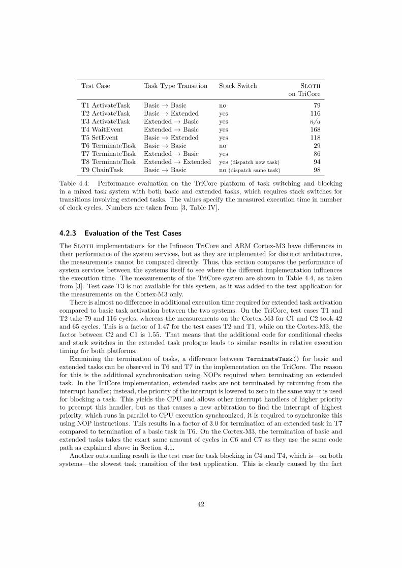
Test Case Task Type Transition Stack Switch Slothon TriCore
T1 ActivateTask Basic → Basic no 79T2 ActivateTask Basic → Extended yes 116T3 ActivateTask Extended → Basic yes n/aT4 WaitEvent Extended → Basic yes 168T5 SetEvent Basic → Extended yes 118T6 TerminateTask Basic → Basic no 29T7 TerminateTask Extended → Basic yes 86T8 TerminateTask Extended → Extended yes (dispatch new task) 94T9 ChainTask Basic → Basic no (dispatch same task) 98
Table 4.4: Performance evaluation on the TriCore platform of task switching and blockingin a mixed task system with both basic and extended tasks, which requires stack switches fortransitions involving extended tasks. The values specify the measured execution time in numberof clock cycles. Numbers are taken from [3, Table IV].
4.2.3 Evaluation of the Test CasesThe Sloth implementations for the Infineon TriCore and ARM Cortex-M3 have differences intheir performance of the system services, but as they are implemented for distinct architectures,the measurements cannot be compared directly. Thus, this section compares the performance ofsystem services between the systems itself to see where the different implementation influencesthe execution time. The measurements of the TriCore system are shown in Table 4.4, as takenfrom [3]. Test case T3 is not available for this system, as it was added to the test application forthe measurements on the Cortex-M3 only.
There is almost no difference in additional execution time required for extended task activationcompared to basic task activation between the two systems. On the TriCore, test cases T1 andT2 take 79 and 116 cycles, whereas the measurements on the Cortex-M3 for C1 and C2 took 42and 65 cycles. This is a factor of 1.47 for the test cases T2 and T1, while on the Cortex-M3, thefactor between C2 and C1 is 1.55. That means that the additional code for conditional checksand stack switches in the extended task prologue leads to similar results in relative executiontiming for both platforms.
Examining the termination of tasks, a difference between TerminateTask() for basic andextended tasks can be observed in T6 and T7 in the implementation on the TriCore. The reasonfor this is the additional synchronization using NOPs required when terminating an extendedtask. In the TriCore implementation, extended tasks are not terminated by returning from theinterrupt handler; instead, the priority of the interrupt is lowered to zero in the same way it is usedfor blocking a task. This yields the CPU and allows other interrupt handlers of higher priorityto preempt this handler, but as that causes a new arbitration to find the interrupt of highestpriority, which runs in parallel to CPU execution synchronized, it is required to synchronize thisusing NOP instructions. This results in a factor of 3.0 for termination of an extended task in T7compared to termination of a basic task in T6. On the Cortex-M3, the termination of basic andextended tasks takes the exact same amount of cycles in C6 and C7 as they use the same codepath as explained above in Section 4.1.
Another outstanding result is the test case for task blocking in C4 and T4, which is—on bothsystems—the slowest task transition of the test application. This is clearly caused by the fact
42

that the run-to-completion model of interrupt handlers does not fit blocking tasks. Hence, theimplementation of WaitEvent() is the most extensive system service, which is reflected in itsexecution time.
Summary
It is difficult to compare the test cases between distinct architectures as the instruction set,addressing modes, pipelining, and other relevant properties of the microcontrollers influence therequired execution cycles. However, the relative comparison of the test cases have shown that onboth platforms, the task prologue of extended tasks requires the same factor of additional cycleswhen compared to basic task management. Also, the extended task termination by changingpriority with manual synchronization of the interrupt arbitration on the TriCore leads to moreadditional cycles than on the Cortex-M3, where basic and extended task termination take thesame amount of cycles.
4.2.4 Summary of the Comparison with the Reference Implementation on theTriCore Platform
The Sloth implementations on the Infineon TriCore and the ARM Cortex-M3 have similarruntime characteristics in most aspects of the task management, although the implementationshave differences as they match the provided hardware functionality. However, both systemsfollow the same central design idea of using the hardware for scheduling purposes by making useof the interrupt controller. This is reflected in the evaluation of the test cases, where the relativecomparison shows that the test scenarios take similar amounts of cycles.
4.3 Limitations
The port to the ARM Cortex-M3 platform is currently bound to the Atmel SAM3U microcon-troller used in this thesis due to the use of the board-specific timer counters. Also, the startupcode and initialization routines target this hardware configuration only. However, the Sloth im-plementation would be portable to any microcontroller using the ARM Cortex-M3 with minimaleffort.
Also, the implemented Sloth system only supports the conformance classes BCC1 and ECC1of the OSEK specification, as shown in Figure 1.1 on page 2. Of the additionally required featuresfor the conformance classes BCC2 and ECC2, support for synchronization using resources andmultiple activations of tasks have already been implemented. The missing feature is supportfor multiple tasks per priority. This is a limitation that cannot be solved easily, as the OSEKspecification states that tasks of the same priority level have to be started in their order ofactivation. Thus, this requirement cannot be fulfilled by an interrupt subsystem without the useof a software scheduler determining which task will be dispatched next.
4.4 Summary
The performance evaluation confirms the Sloth concept, as it shows the advantages of utilizinghardware for scheduling. In comparison with another OSEK-conforming operating system, theSloth implementation for the ARM Cortex-M3 outperformed the competitor with a software-based scheduler by a factor ranging from 2.5 to 25.9. The comparison with Sloth on the Infineon
43
TriCore shows that the different hardware influences the implementation details of the systemservices. However, the performance of the individual system services for task management aresimilar in the relative comparison.
44
Chapter 5
Conclusion
For this thesis, the Sloth concept of using interrupt controlling hardware for thread schedulingand dispatching purposes was examined on the ARM Cortex-M3 hardware platform. The goalof the Sloth concept is to omit a scheduler in software and use the interrupt subsystem insteadby using interrupt handlers as a universal abstraction for control flows. The presented featuresof the Cortex-M3 platform were used to design and implement an operating system kernel basedon the Sloth concept.
The implemented system was evaluated in different configurations and results were comparedwith another implementation using a software-based scheduler. With a speedup ranging from2.5 to 25.9, the results show the positive effects of the Sloth concept onto the non-functionalproperties of the operating system.
The similarities and differences to the original Sloth reference implementation on the TriCoreplatform show that any Sloth implementation for a specific platform will be hardware-dependentin large parts, as each architecture has their own interfaces and peculiarities. However, the Slothconcept can be implemented on any platform that fulfills the basic requirements on the interruptcontroller: different priority levels for each interrupt, support for triggering interrupts in software,and support for raising the current execution priority as a synchronization mechanism.
By modeling all control flows as interrupts in Sloth, the distinction between threads andinterrupts is gone. Therefore, they can share the same priority space managed by the hardware,which avoids the problem of rate-monotonic priority inversion and allows assigning prioritiesarbitrarily between threads and interrupts.
The Sloth concept as described in this thesis could be implemented on any platform fulfillingthe requirements on the hardware. In future work, Sloth needs to follow the ongoing trend ofmulti-core and multi-processor systems, which is spreading to the world of embedded systems atthe moment. With multiple processor units, and therefore more complex scheduling decisions tomake, a multi-core system would benefit from support by the hardware to improve the perfor-mance. Extending the Sloth concept for use in multi-processor systems will be an interestingchallenge.
45


Bibliography
[1] Luis E. Leyva del Foyo, Pedro Mejia-Alvarez, and Dionisio de Niz. Predictable interruptmanagement for real time kernels over conventional PC hardware. In Proceedings of the 12thIEEE International Symposium on Real-Time and Embedded Technology and Applications(RTAS 2006), pages 14–23, Los Alamitos, CA, USA, 2006. IEEE Computer Society.
[2] Wanja Hofer, Daniel Lohmann, Fabian Scheler, and Wolfgang Schröder-Preikschat. Sloth:Threads as interrupts. In Proceedings of the 30th IEEE Real-Time Systems Symposium(RTSS 2009), pages 204–213, Los Alamitos, CA, USA, 2009. IEEE Computer Society.
[3] Wanja Hofer, Daniel Lohmann, and Wolfgang Schröder-Preikschat. Sleepy Sloth: Threadsas interrupts as threads. In Proceedings of the 32nd IEEE Real-Time Systems Symposium(RTSS 2011), to appear, pages 67–77, Los Alamitos, CA, USA, December 2011. IEEE Com-puter Society.
[4] OSEK/VDX Group. Operating system specification 2.2.3. Technical report, OSEK/VDXGroup, February 2005. http://portal.osek-vdx.org/files/pdf/specs/os223.pdf.
[5] Infineon Technologies AG. TriCore 1 User’s Manual, V1.3.8, Volume 1: Core Architecture,January 2008.
[6] ARM. Cortex-M3 Technical Reference Manual, February 2010. http://infocenter.arm.com/help/topic/com.arm.doc.ddi0337h/index.html.
[7] ARM introduces the Cortex-M3 processor to deliver high performance in low-cost applica-tions. http://arm.com/about/newsroom/6750.php, Oct 2004.
[8] ARM. ARMv7-M Architecture Reference Manual, November 2010.
[9] Joseph Yiu. The Definitive Guide to the ARM Cortex-M3. Newnes, 2009.
[10] Atmel. SAM3U Series, March 2011. http://www.atmel.com/dyn/resources/prod_documents/doc6430.pdf.
[11] ARM. Procedure Call Standard for the ARM Architecture, October 2009. http://infocenter.arm.com/help/topic/com.arm.doc.ihi0042d/index.html.
[12] Free Software Foundation, Inc. GCC 4.5 release series. Changes, new features, and fixes.http://gcc.gnu.org/gcc-4.5/changes.html, 2011.
[13] Free Software Foundation, Inc. Using the GNU compiler collection (GCC) – section 6.41:Assembler instructions with C expression operands. http://gcc.gnu.org/onlinedocs/gcc/Extended-Asm.html, 2011.
47

[14] ArcCore AB. Arctic Core - the open source AUTOSAR embedded platform. http://arccore.com.
[15] Infineon Technologies AG. TriCore 1 User’s Manual, V1.3.8, Volume 2: Instruction Set,January 2008.
48