“implementation and evaluation of modbus protocol”nishu/papers/be_2005.pdf“implementation and...
TRANSCRIPT
A Project Report on
“Implementation and Evaluation of Modbus Protocol”
Under the guidance of
Prof. Mrs. S. V. Kedar
By: Deshmukh Nishikant Pramod (B2374205)
Rathi Anand Kamalkishor (B2374222) Raskar Tushar Vijay (B2374221)
Raut Digvijay Dattatray (B2374224)
In Partial Fulfillment of BE (Computer Engineering)
Degree Course of University of Pune
2004 – 2005
Department of Computer Engineering

2
Rajarshi Shahu College of Engineering Pune - 411033
ACKNOWLEDGEMENT
We express our deepest thanks to our project guide Prof S. V. Kedar for her Technical
support, guidance, encouragement and moral support without which it would have been difficult
to complete this project work.
We sincerely wish to express our grateful thanks to our Project Guide for his valuable
suggestions.
It is our earnest endeavor to express sincere thanks to Prof Mr. S. T. Singh (HOD) for
their kind co-operation, help and delighted support.
We are thankful to our entire staff of Computer Engineering Department specially for
providing time to time help and their valuable guidance to make this work possible.

3
ABSTRACT
Industrial Automation has been important aspect of Industrial Revolution. Microcontrollers were
integrated with Machines for controlling them. Soon the concept of controlling devices remotely
came into picture. Thanks to network interfaces supported by microcontrollers, all this things
were possible. With the advent of advanced computer technology it became desirable to connect
those devices with PC. Different Vendors starting implementing there own protocols. One of
these protocols which have now become Industrial software was developed by Modicon.
Modbus is a Master Slave Protocol in which PC acts like a Master and other devices acts as
Slaves.
In our project we have implemented this protocol in Java (Master) and embedded C
(slave) .On PC side we have designed a device manager “Modbus Browser” which detects serial
ports on your machine and allows adding of devices with unique device address per port.
Commands can be later added for each device. Communication is half duplex and when proper
response is received from device it is stored in database.
As an further extension we have tried to connect two Browsers together so that devices
can be controlled remotely from Browser to Browser.

4
Implementation and Evaluation of Modbus Protocol

5
INDEX
Chapter No. TITLE Page No.
1. Introduction
1.1 System Description………………………………………………… 9
1.1.1 Modbus Browser……………………………………………. 9
1.1.2 Database…………………………………………………….. 10
1.2 Further Extension…………………………………………………… 11
1.3 Software Requirement Specification……………………………….. 12
1.3.1 Introduction…………………………………………………. 12
1.3.1.1 Purpose…………………………………………………… 12
1.3.1.2 Scope of Product…………………………………………. 12
1.3.2 General Description………………………………………….. 13
1.3.2.1 Product Perspective……………………………………… 13
1.3.2.2 User Characteristics……………………………………… 13
1.3.3 General Constraints………………………………………….. 14
1.3.4 Specific Requirements……………………………………….. 14
1.3.4.1 Functional Requirements……………………………….... 14
2. Literature
2.1 Protocol Description………………………………………………….. 17
2.2 Serial Transmission Format………………………………………….. 20
2.3 Modbus Message Framing…………………………………………... 21
2.4 ASCII Transmission Mode…………………………………………... 24
2.4.1 MODBUS Message ASCII Framing……………………….... 25
2.5 RTU Transmission Mode……………………………………………. 26
2.5.1 MODBUS Message RTU Framing………………………….. 28
2.6 Error Checking Methods…………………………………………….. 29
2.6.1 CRC checking……………………………………………….. 29
2.6.2 LRC checking……………………………………………….. 29
2.6.3 Parity checking…………………………………………….... 29
3. Design
3.1 Data Flow Diagrams………………………………………………… 32
3.1.1 Level 0 DFD………………………………………………… 32
3.1.2 Level 1 DFD………………………………………………… 33
3.1.3 Level 2A DFD……………………………………………..... 34
3.1.4 Level 2B DFD………………………………………………. 35
3.1.5 Level 2C DFD………………………………………………. 36
3.1.6 Level 2D DFD………………………………………………. 37
3.1.7 Level 2E DFD………………………………………………. 38
3.1.8 Level 2F DFD………………………………………………. 39
3.1.9 Level 2G DFD…………………………………………........ 40
3.2 UML Diagrams……………………………………………………... 41
3.2.1 Use Case Diagram………………………………………….. 41

6
3.2.2 Class Diagram……………………………………………… 42
3.2.3 Sequence Diagram.................................................................. 43
3.2.3.1 Sequence Diagram for Device………………………….. 43
3.2.3.2 Sequence Diagram for Network………………………... 44
3.2.4 Activity Diagram…………………………………………… 45
3.2.5 State Diagram………………………………………………. 46
3.2.5.1 State Diagram for Master…………………………...........47
3.2.5.2 State Diagram for Slave………………………………... 48
3.2.6 Component Diagram……………………………………….. 49
3.2.7 Deployment Diagram………………………………………. 50
3.3 Database Design……………………………………………………. 50
4. Implementation
4.1 System Implementation…………………………………….………. 53
4.1.1 Basic………………………………………………………... 54
4.1.2 Mytree…………………………………………………….… 54
4.1.3 Scheduler………………………………………………….... 54
4.1.4 Server…………………………………………………….…. 54
4.1.5 Queue…………………………………………………….…. 55
4.1.6 Send……………………………………………………........ 55
4.1.7 Databas……………………………………………………... 55
4.2 Data Dictionary……………………………………………….……. 56
4.2.1 File: basic.java……………………………….…………….. 56
4.2.2 device.java……………………………………….………… 57
4.2.3 deviceData.java………………………………….…………. 57
4.2.4 errorcode.java…………………………………….………… 57
4.2.5 lineparser.java…………………………………….………... 57
4.2.6 databas.java………………………………………….……... 58
4.2.7 mytree.java………………………………………….……… 58
4.2.8 SerialParameters.java……………………………….……… 58
4.3 Algorithm…………………………………………………….…….. 59
4.3.1 lineparser…………………………………………….……... 59
4.3.2 comportIdentification…………………………………….… 60
4.3.3 removeDevice……………………………………….……… 61
4.3.4 removeNetwork……………………………………….……. 62
4.3.5 deleteCommand……………………………………….……. 62
4.3.6 scheduler…………………………………………….……… 63
4.3.7 showIcons…………………………………………….……. . 64
4.3.8 Master to Master Connection………………………….…… 65
4.3.9 Errorcode…………………………………………….……... 68
5. Testing
5.1 Test Plan……………………………………………………………. 72
5.1.1 Unit-Testing............................................................................ 72
5.1.1.1 Mytree…………………………………………………... 73
5.1.1.2 Error Code…………………………………………….... 74

7
5.1.1.3 lineParser……………………………………………….. 75
5.1.1.4 fileUtil…………………………………………………... 77
5.1.2 Integration Testing………………………………………….. 79
5.1.2.1 Bottom-up Testing……………………………………… 80
5.1.3 Validation Testing………………………………………….. 82
5.1.3.1 Validation Testing for User Interface…………………... 83
5.1.3.2 Validation Testing for DMS…………………………….. 83
6. Result
6.1 Modbus Browser…………………………………………………... 85
6.2 Default Network…………………………………………………… 86
6.3 Adding of device command……………………………………….. 88
6.4 Communication with device……………………………………….. 90
6.5 Device Information………………………………………………… 92
6.6 Configure Device…………………………………………………... 93
6.7 Remove Device…………………………………………………….. 97
7. Conclusion
7.1 Conclusions………………………………………………………… 100
7.2 Applications of the system…………………………………………. 100
7.3 Limitations…………………………………………………………. 100
7.4 Future Scopes………………………………………………………. 100
8. Bibliography
8.1 Books………………………………………………………………. 102
8.2 Websites…………………………………………………………… 102

8
Chapter 1
Introduction

9
1. Introduction
1.1 System Description
1.1.1 Modbus Browser:
Modbus Browser is a device manager which helps in maintaining all
device information and allows adding and deleting commands supported by a modbus device.
Modbus protocol can be implemented over serial line or TCP/IP. Our project deals with
implementing it over serial line. Modbus Browser is implemented in Java and has well defined
Graphics User Interface in Java Swing.
Fig 1.1: System Block Diagram
Modbus Protocol is a Master Slave Protocol in which a PC acts as a
Master and Device acts as a slave. In our case Modbus Browser acts as a Master and Devices
acts as a slave.
We have written a small slave side software in embedded C for
Microcontroller to simulate actual interaction with hardware.
Modbus
Browser
Modbus
Device
Modbus
Device
database
10
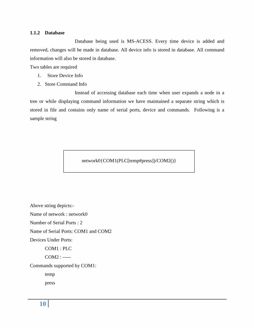
1.1.2 Database
Database being used is MS-ACESS. Every time device is added and
removed, changes will be made in database. All device info is stored in database. All command
information will also be stored in database.
Two tables are required
1. Store Device Info
2. Store Command Info
Instead of accessing database each time when user expands a node in a
tree or while displaying command information we have maintained a separate string which is
stored in file and contains only name of serial ports, device and commands. Following is a
sample string
Above string depicts:-
Name of network : network0
Number of Serial Ports : 2
Name of Serial Ports: COM1 and COM2
Devices Under Ports:
COM1 : PLC
COM2 : -----
Commands supported by COM1:
temp
press
network0{COM1(PLC[temp#press])/COM2()}

11
1.2 Further Extension:
Master-to-Master Connection
As a further Extension we have tried to connect two Masters remotely
and make their devices visible to each other. Further they can start and stop their devices
remotely.
Fig 1.2: Subsystem Block Diagram
The network string depicted in previous section is transferred to server and
on request by another master this string will be transferred which will be added to configuration
file with new network name.
Modbus
Browser1
Modbus
Browser2
Server

12
1.3 Software Requirement Specification:
1.3.1 Introduction:
1.3.1.1 Purpose:
The purpose of requirement specification is to specify both functional and
non-functional requirements to the user. This is an initial phase of development of project in
which detailed requirements has been collected from company and provided in details all
negotiated functions to be added in project.
1.3.1.2 Scope of Product:
The purpose of this software development project is to implement
MODBUS protocol. MODBUS protocol is an Industrial standard protocol to connect remote
Modbus devices to a PC. By doing so, we can control devices remotely by a PC. Following are
the capabilities that will be provided by software.
1. Auto Detection of serial ports.
2. Facility to add devices on given comports.
3. Add commands for a specific device.
4. Start a device
5. Stop a device
6. Connect to other Modbus browsers.
7. Add other networks with your current network.
8. Start and Stop devices of other network.
9. Easy to use GUI.
10. Generic for serial devices (i.e. supports any device)
13
1.3.2 General Description:
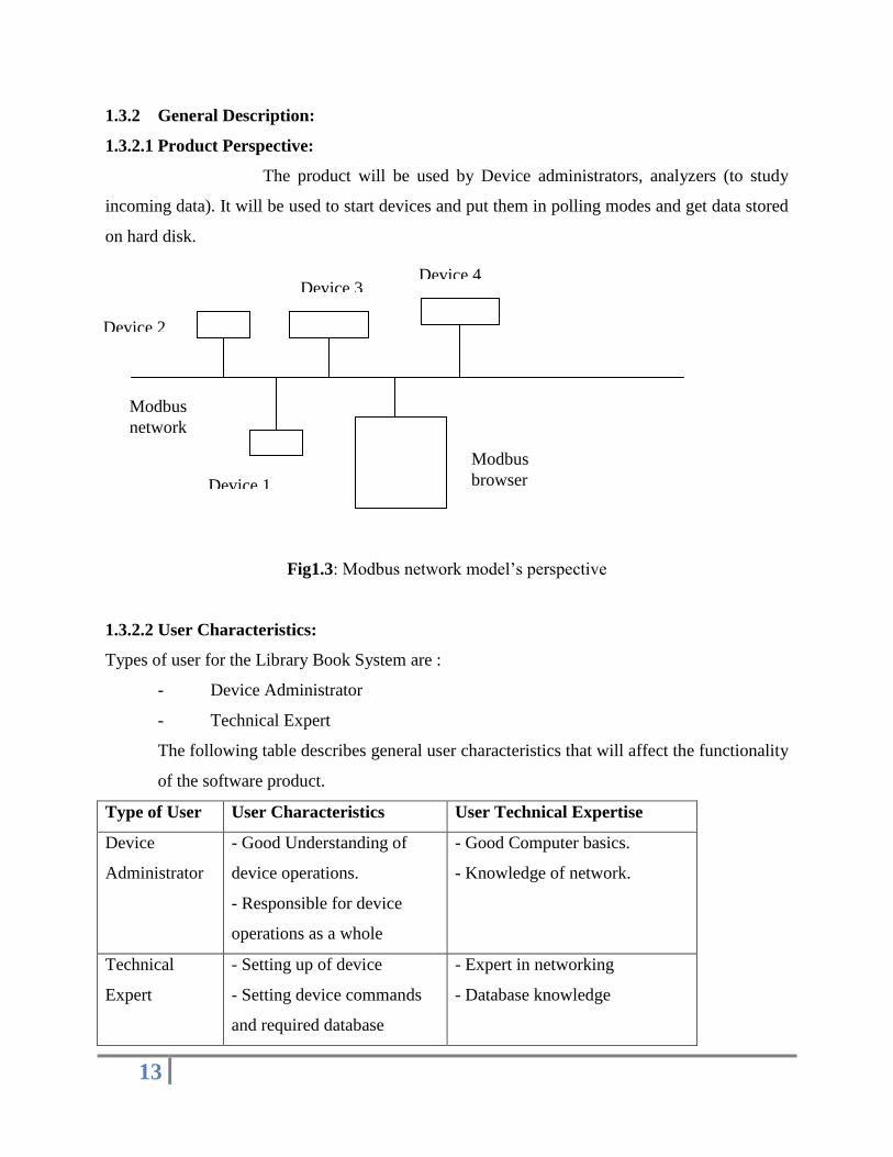
1.3.2.1 Product Perspective:
The product will be used by Device administrators, analyzers (to study
incoming data). It will be used to start devices and put them in polling modes and get data stored
on hard disk.
Fig1.3: Modbus network model‟s perspective
1.3.2.2 User Characteristics:
Types of user for the Library Book System are :
- Device Administrator
- Technical Expert
The following table describes general user characteristics that will affect the functionality
of the software product.
Type of User User Characteristics User Technical Expertise
Device
Administrator
- Good Understanding of
device operations.
- Responsible for device
operations as a whole
- Good Computer basics.
- Knowledge of network.
Technical
Expert
- Setting up of device
- Setting device commands
and required database
- Expert in networking
- Database knowledge
Modbus
network
Device 1
Device 2
Device 3 Device 4
Modbus
browser

14
1.3.3 General Constraints:
The current hardware requirement for the Modbus browser is Pentium III
Processor or more with 128 MB RAM and at least one serial port.
Software requirements are Windows 98 /2000/XP with JRE 1.4.2 or more
and CommAPI libraries.
The limit of Modbus device connected to a PC can be 255.
Security is important. Only user on a PC can change device configuration.
It cannot be changed remotely.
1.3.4 Specific Requirements:
This section contains the detailed requirements.
1.3.4.1 Functional Requirements:
User interface:
The user interface requirements are concerned with the user interface and
how information is presented to the user.
Device Management System:
1 The System shall display device information including device name and address and
serial parameter settings.
2 GUI will be used which will allow users to add and remove devices , adding and
removing commands.
Network Management System:
1 System shall connect to the modbus server in order to get device lists.
2 User will be free to add other Modbus networks.
3 Network will be displayed in a tree structure.
4 User is free to start and stop devices of other networks.

15
Chapter 2
Literature

16
2. MODBUS PROTOCOL:[2]
“The MODBUS protocol defines a message structure that controllers will recognize and
use, regardless of the type of network over which they communicate.”[2]
“ It describes:[2]
• The process a controller uses to request access to other devices,
• How it will respond to requests from the other devices, and
• How errors will be detected and reported.”[2]
“MODBUS is an application layer messaging protocol, positioned at level 7 of the OSI
model that provides client/server communication between devices connected on different types
of buses or networks.”[2]
“MODBUS is a request/reply protocol and offers services specified by
function codes. MODBUS function codes are elements of MODBUS request/reply PDUs.[2]
The objective of this document is to describe the function codes used within the framework of
MODBUS transactions.”[2]

17
2.1 Protocol description
“The MODBUS protocol defined a simple protocol data unit (PDU)
independent of the underlying communication layers. The mapping of MODBUS protocol on
specific buses or network can introduce some additional fields on the application data unit
(ADU).”[2]
Fig 1.1:Modbus ADU
“The MODBUS application data unit is built by the client that initiates a MODBUS
transaction.[2] The function indicates to the server what kind of action to perform.[2] The
MODBUS application protocol establishes the format of a request initiated by a client. [2] The
function code field of a MODBUS data unit is coded in one byte. Valid codes are in the range of
1 ... 255 decimal (128 – 255 reserved for exception responses). [2] When a message is sent from
a Client to a Server device the function code field tells the server what kind of action to perform.
Sub-function codes are added to some function codes to define multiple actions.[2] The data
field of messages sent from a client to server devices contains additional information that the
server uses to take the action defined by the function code. [2] This can include items like
discrete and register addresses, the quantity of items to be handled, and the count of actual data
bytes in the field.[2] The data field may be nonexistent (of zero length) in certain kind of request,
in this case the server does not require any additional information.[2] The function code alone
specifies the action [2]. If no error occurs related to the MODBUS function requested in a
properly received MODBUS ADU the data field of a response from a server to a client contains
the data requested[2]. If an error related to the MODBUS function requested occurs, the field
contains an exception code that the server application can use to determine the next action to be
taken[2]. When the server responds to the client, it uses the function code field to indicate either

18
a normal (error-free) response or that some kind of error occurred (called an exception
response)[2]. For a normal response, the server simply echoes the original function code.”[2]
Fig 1.2: MODBUS transaction (error free)
“For an exception response, the server returns a code that is equivalent to the original function
code with its most significant bit set to logic 1.”[2]
Fig 1.3: MODBUS transaction (exception response)
“The MODBUS request consists of:[2]
• An address,
• A function code defining the requested action,

19
• Data (if necessary for the requested function), and
• Error check for testing the integrity of the message.”
“The slave‟s response contains:[2]
• The slave address,
• Data conform the request type, and
• Error check.
If the data integrity test fails, no response is sent back.[2] If a request cannot be processed
an exception message is returned.”[2]
“The size of the MODBUS PDU is limited by the size constraint inherited from the first
MODBUS implementation on Serial Line network (max. RS485 ADU = 256 bytes).” [2]
“Therefore, MODBUS PDU for serial line communication = 256 -
Server address (1 byte) - CRC (2 bytes) = 253 bytes. [2]”
“Consequently:
RS232 / RS485 ADU = 253 bytes + Server address (1 byte) + CRC (2
bytes) = 256 bytes.
TCP MODBUS ADU = 249 bytes + MBAP (7 bytes) = 256 bytes.
The MODBUS protocol defines three PDUs.
They are:
MODBUS Request PDU, mb_req_pdu [2]
MODBUS Response PDU, mb_rsp_pdu [2]
MODBUS Exception Response PDU, mb_excep_rsp_pdu” [2]

20
2.2 Serial Transmission Format [2]
“The two transmission modes used are called: [2]
1. ASCII, and
2. RTU.
The user has to select the desired mode along with the serial communication parameters
(baud rate, parity type). [2]
Note that all these parameters must be the same for all controllers in the network.” [2]
2.2.1 ASCII-mode [2]
“• Each byte of the message is sent as two ASCII characters. [2]
This means only the ASCII characters 0-9, A-F are transmitted. [2]
• Serial communication parameters: [2]
1 Start bit, 7 data bits, even/odd/no parity, 1 stop bit if parity is used and
two stop bits if no parity is used.
• Error check field:[2]
Longitudinal Redundancy Check (LRC).
The advantage of ASCII mode is that it allows for a time interval up to 1 second between
characters without causing a timeout. [2]
A disadvantage of ASCII mode is the larger message length.” [2]
2.2.2 RTU-mode [2]
“• Each byte of the message is sent as 8 bits. [2]
• Serial communication parameters: [2]
1 start bit, 8 data bits, even/odd/no parity, 1 stop bit if parity is used, and two stop bits if no
parity is used. [2]
• Error check field: [2]
Cyclic Redundancy Check (CRC).”

21
2.3 Modbus Message Framing [2]
2.3.1 ASCII-MODE [2]
“In ASCII-mode a message starts with a colon character (:) and ends with a carriage
return–linefeed. Intervals up to one second can elapse between characters within the message. [2]
If the interval is longer, a timeout error occurs and the message is rejected.” [2]
2.3.2 RTU mode [2]
“In RTU-mode a message starts with a silent interval of at least 3.5 character times. [2]
The entire message frame must be transmitted as a continuous stream. [2] If a silent interval of
more than 3.5 character times occurs before completion of the frame, the receiving device
flushes the incoming message and assumes that the next byte will be the address field for the
new message.” [2]
“Messages start with a silent interval of at least 3.5 character times. [2]This is easily
implemented as a multiple of character times at the baud rate used on the network (shown as T1-
T2- T3-T4 in the table below).[2] The first field then transmitted is the device address.[2] The
allowed characters transmitted for all fields are hexadecimal 0-9, A-F. Network devices monitor
the network bus continuously, including during the ‟silent‟ intervals.[2] When the first field (the
address field) is received, each device decodes it to find out if it is the addressed device. [2]
Following the last transmitted character, a similar interval of at least 3.5 character times marks
the end of the message.[2] A new message can begin after this interval.[2] The entire message
frame must be transmitted as a continuous stream. [2] If a silent interval of more than 3.5
character times occurs before completion of the frame, the receiving device flushes the
incomplete message and assumes that the next byte will be the address field of a new message.
[2] Similarly, if a new message begins earlier than 3.5 character times following a previous

22
message, the receiving device will consider it a continuation of the previous message. [2] This
will set an error, as the value in the final CRC field will not be valid for the combined messages.
[2] A typical message frame is shown below.”[2]
The Address Field [2]
“The address field of a message frame contains:
• 2 characters (ASCII-mode) or
• 8 bits (RTU-mode).
Valid slave addresses are 1 to 247.
Address 0 is used for a broadcast to address all slaves.”
The Function Field [2]
“The function field of a message frame contains:
• 2 characters (ASCII-mode) or
• 8 bits (RTU-mode).
Valid codes lie in a range of 1 to 127. [2]
The function code tells the slave which kind of action to perform. A slave response
always contains the function code of the request. If a function is not applicable, the slave sends
an exception response. An exception is indicated by a returned function code with bit 8 (most
significant byte) set.”

23
The Data Field [2]
“The data field contains 8 bit values in the range of 0 to FF hexadecimal.[2] In ASCII
mode this byte is made of 2 ASCII characters.[2] The data field of messages contains
information which both master and slave use to perform an action.[2] This includes the register
address, quantity of registers, and the necessary data.” [2]
The Error Checking Field [2]
“The error checking field contents depend on the transmission mode.[2] Two kinds of
error methods are used.” [2]
Error check with ASCII-mode [2]
“When the ASCII mode is used, the error-checking field contains two ASCII characters.
[2] The error check characters are the result of a Longitudinal Redundancy Check calculation.
[2] This Is performed on the message contents with exception of the beginning colon, the
carriage return and line feed characters. [2] The LRC characters are appended to the message as
the last field preceding the CR-LF characters.” [2]
Error check with RTU-mode [2]
“When RTU mode is used, the error-checking field contains a 16-bit value implemented
as two bytes.[2] The error check value is the result of a Cyclic Redundancy Check calculation
performed on the message contents.[2] The CRC field is appended to the message as the last
field.” [2]
Errors, exception codes [2]
“Two kinds of errors are possible: [2]
- Transmission errors. [2]
- Operation errors.” [2]

24
2.4 ASCII Transmission Mode [2]
“When devices are setup to communicate on a MODBUS serial line using ASCII
(American Standard Code for Information Interchange) mode, each 8–bit byte in a message is
sent as two ASCII characters. [2] This mode is used when the physical communication link or
the capabilities of the device does not allow the conformance with RTU mode requirements
regarding timers management.” [2]
“Remark: this mode is less efficient than RTU since each byte needs two characters.[2]
_ Example: The byte 0X5B is encoded as two characters: 0x35 and 0x42 (0x35 ="5", and 0x42
="B" in ASCII).” [2]
The format for each byte (10 bits) in ASCII mode is:[2]
Coding System: “Hexadecimal, ASCII characters 0–9, A–F [2]
One hexadecimal character contains 4-bits of data within each ASCII character of the
message [2]”
Bits per Byte: “1 start bit
7 data bits, least significant bit sent first
1 bit for parity completion;
1 stop bit”
Even parity is required;[2] “other modes (odd parity, no parity) may also be used. In order to
ensure a maximum compatibility with other products, it is recommended to support also No
parity mode. The default parity mode must be even parity. Remark: the use of no parity requires
2 stop bits.”
How Characters are transmitted serially:[2]
“Each character or byte is sent in this order (left to right):
Least Significant Bit (LSB) . . . Most Significant Bit (MSB)”

25
Bit Sequence in ASCII mode [2]
“Devices may accept by configuration either Even, Odd, or No Parity checking. If No
Parity is implemented, an additional stop bit is transmitted to fill out the character frame [2]”
Bit Sequence in ASCII mode (specific case of No Parity) [2]
Frame Checking Field: “Longitudinal Redundancy Checking (LRC) [2]”
2.4.1 MODBUS Message ASCII Framing [2]
“A MODBUS message is placed by the transmitting device into a frame that has a known
beginning and ending point. [2] This allows devices that receive a new frame to begin at the
start of the message, and to know when the message is completed. [2] Partial messages must
be detected and errors must be set as a result. [2] The address field of a message frame
contains two characters.”[2]
“In ASCII mode, a message is delimited by specific characters as Start-of-frames
and End-of-frames. A message must start with a ‘colon’ ( : ) character (ASCII 3A hex), and end with a
‘carriage return – line feed’ (CRLF) pair (ASCII 0D and 0A hex).” [2]
“Remark: The LF character can be changed using a specific MODBUS application command (see
MODBUS application protocol specification). The allowable characters transmitted for all other fields are
hexadecimal 0–9, A–F (ASCII coded). The devices monitor the bus continuously for the „colon‟
character. When this character is received, each device decodes the next character until it detects the End-
Of-Frame. Intervals of up to one second may elapse between characters within the message. Unless the
user has configured a longer timeout, an interval greater than 1 second means an error has occurred.

26
Some Wide-Area-Network application may require a timeout in the 4 to 5 second range. A typical
message frame is shown below.” [2]
ASCII Message Frame [2]
“Remark: Each data byte needs two characters for encoding. [2] Thus, to ensure compatibility at
MODBUS application level between ASCII mode and RTU mode, the maximum data size for
ASCII data field (2x252) is the double the maximum data size for RTU data field (252). [2]
Consequently, the maximum size of a MODBUS ASCII frame is 513 characters”. [2]
2.5 RTU Transmission Mode [2]
“When devices communicate on a MODBUS serial line using the RTU (Remote
Terminal Unit) mode, each 8–bit byte in a message contains two 4–bit hexadecimal characters.
[2] The main advantage of this mode is that its greater character density allows better data
Throughput than ASCII mode for the same baud rate.[2] Each message must be transmitted in a
continuous stream of characters.”[2]
The format for each byte (11 bits) in RTU mode is: [2]
Coding System: 8–bit binary [2]
Bits per Byte: 1 start bit [2]
8 data bits, least significant bit sent first [2]
1 bit for parity completion
1 stop bit
“Even parity is required; other modes (odd parity, no parity) may also be used. [2] In order to
ensure a maximum compatibility with other products, it is recommended to support also No
parity mode. [2] The default parity mode must be even parity. [2]
Remark: the use of no parity requires 2 stop bits. [2]”

27
How Characters are transmitted serially: [2]
“Each character or byte is sent in this order (left to right): [2]
Least Significant Bit (LSB) . . . Most Significant Bit (MSB) [2]”
Bit Sequence in RTU Mode [2]
“Devices may accept by configuration either Even, Odd, or No Parity checking. [2] If No
Parity is implemented, an additional stop bit is transmitted to fill out the character frame to a full
11-bit asynchronous character. [2]”
Bit Sequence in RTU Mode (specific case of No Parity) [2]
Frame Checking Field: Cyclical Redundancy Checking (CRC) [2]
RTU Message Frame [2]
“The maximum size of a MODBUS RTU frame is 256 bytes. [2]”

28
2.5.1 MODBUS Message RTU Framing [2]
“A MODBUS message is placed by the transmitting device into a frame that has a known
beginning and ending point. [2] This allows devices that receive a new frame to begin at the start
of the message, and to know when the message is completed. [2] Partial messages must be
detected and errors must be set as a result. [2] In RTU mode, message frames are separated by a
silent interval of at least 3.5 character times. [2]”
RTU Message Frame [2]
“The entire message frame must be transmitted as a continuous stream of characters. [2]
If a silent interval of more than 1.5 character times occurs between two characters, the message
frame is declared incomplete and should be discarded by the receiver. [2]”
“Remark: The implementation of RTU reception driver may imply the management of a lot of
interruptions due to the t1.5 and t3.5 timers. [2] With high communication baud rates, this leads
to a heavy CPU load. [2] Consequently these two timers must be strictly respected when the
baud rate is equal or lower than 19200 Bps. [2] For baud rates greater than 19200 Bps, fixed
values for the 2 timers should be used: it is recommended to use a value of 750µs for the inter-
character time-out (t1.5) and a value of 1.750ms for inter-frame delay (t3.5). [2]”

29
2.6 Error Checking Methods [2]
2.6.1 CRC Checking [2]
“The RTU mode includes an error–checking field that is based on a
Cyclical Redundancy Checking (CRC) method performed on the message contents.[2] The CRC
field checks the contents of the entire message. [2] It is applied regardless of any parity checking
method used for the individual characters of the message. [2] The CRC field contains a 16–bit
value implemented as two 8–bit bytes. [2] The CRC field is appended to the message as the last
field in the message.[2] When this is done, the low–order byte of the field is appended first,
followed by the high–order byte.[2] The CRC high–order byte is the last byte to be sent in the
message.[2] The CRC value is calculated by the sending device, which appends the CRC to the
message. [2] The receiving device recalculates a CRC during receipt of the message, and
compares the calculated value to the actual value it received in the CRC field. [2] If the two
values are not equal, an error results. [2] The CRC calculation is started by first pre-loading a
16–bit register to all 1‟s. [2] Then a process begins of applying successive 8–bit bytes of the
message to the current contents of the register. [2] Only the eight bits of data in each character
are used for generating the CRC. [2] Start and stop bits and the parity bit, do not apply to the
CRC. [2] During generation of the CRC, each 8–bit character is exclusive ORed with the register
contents. [2] Then the result is shifted in the direction of the least significant bit (LSB), with a
zero filled into the most significant bit (MSB) position. [2] The LSB is extracted and examined.
[2] If the LSB was a 1, the register is then exclusive ORed with a preset, fixed value. [2] If the
LSB was a 0, no exclusive OR takes place. [2] This process is repeated until eight shifts have
been performed. [2] After the last (eight) shift, the next 8–bit byte is exclusive ORed with the
register‟s current value, and the process repeats for eight more shifts as described above. [2] The
final content of the register, after all the bytes of the message have been applied, is the CRC
value. [2] When the CRC is appended to the message, the low-order byte is appended first,
followed by the high-order byte. [2]”
2.6.2 LRC Checking
“In ASCII mode, messages include an error–checking field that is based
on a Longitudinal Redundancy Checking (LRC) calculation that is performed on the message
contents, exclusive of the beginning „colon‟ and terminating CRLF pair characters. [2] It is

30
applied regardless of any parity checking method used for the individual characters of the
message. [2] The LRC field is one byte, containing an 8–bit binary value. [2] The LRC value is
calculated by the device that emits, which appends the LRC to the message. [2] The device that
receives calculates an LRC during receipt of the message, and compares the calculated value to
the actual value it received in the LRC field. [2] If the two values are not equal, an error results.
[2] The LRC is calculated by adding together successive 8–bit bytes of the message, discarding
any carries, and then two‟s complementing the result. [2] It is performed on the ASCII message
field contents excluding the „colon‟ character that begins the message, and excluding the CRLF
pair at the end of the message. [2] In ASCII mode, the resulting LRC is ASCII encoded into two
bytes and placed at the end of ASCII mode frame prior to the CRLF. [2]”
2.6.3 Parity Checking [2]
“Users may configure devices for Even (required) or Odd Parity checking, or for No Parity checking (recommended). This will determine how the parity bit will be set in each character. If either Even or Odd Parity is specified, the quantity of 1 bit will be counted in the data
portion of each character (seven data bits for ASCII mode, or eight for RTU). The parity bit will then be set to a 0 or 1 to result in an Even
or Odd total of 1 bit. [2]”
“For example, these eight data bits are contained in an RTU character frame: 1100 0101 The total quantity of 1 bit in the frame is four. If
Even Parity is used, the frame‟s parity bit will be a 0, making the total quantity of 1 bits still an even number (four). If Odd Parity is used, the parity bit will be a 1, making an odd quantity (five). When the message is transmitted, the parity bit is calculated and applied to the
frame of each character. The device that receives counts the quantity of 1 bit and sets an error if they are not the same as configured for that
device (all devices on the MODBUS Serial Line must be configured to use the same parity checking method). [2]”
“Note that parity checking can only detect an error if an odd number of
bits are picked up or dropped in a character frame during transmission. [2]For example, if Odd
Parity checking is employed, and two 1 bits are dropped from a character containing three 1 bits,
the result is still an odd count of 1 bits. [2]If No Parity checking is specified, no parity bit is
transmitted and no parity checking can be made. [2] An additional stop bit is transmitted to fill
out the character frame. [2]”

31
Chapter 3
Design

32
3. Design
3.1 Data Flow Diagrams
3.1.1 Level 0 DFD
Overall System
User Input
Modbus
Browser
Device

33
3.1.2 LEVEL 1 DFD
Modbus Browser
User
Device
manager
Network
manager
Scheduler Storage
Queue
manager
Device
management
File
User command
Add device
Start Stop
Remove
n/w
Save
Add command
Remove
device
Remove
command Command
manager
Command
interpreter
Save
Saved
Store
Save Save
Save
Storage
manager
Add/remove
from queue
Write
Command

34
3.1.3 LEVEL 2A DFD
Command Interpretation
User command event
Switch
Pass action
event
Call appropriate function
Various commands

35
3.1.4 LEVEL 2B DFD
Scheduler
Action selector
Start
Stop
Start Stop
Start new device
to queue
manager
Stop device
to queue
manager
Remove command
modes
Queue - delete
Add command
modes
Queue - add

36
3.1.5 LEVEL 2C DFD
Command Manager
Remove
command
Save type
interpreter
Add
command
Remove
command
Switch
Add
Remove
Add -
handle
Remove -
handle
Add
command
37
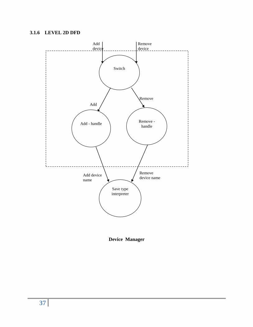
3.1.6 LEVEL 2D DFD
Device Manager
Add
device
Remove
device
Switch
Add
Remove
Add - handle
Remove -
handle
Save type
interpreter
Remove
device name Add device
name

38
3.1.7 LEVEL 2E DFD
Network Manager
Storage
File manager
Switch
Configuration
string handler
Mod client
Network
remove
handler
Add
network
handler
Remove
network
Remove
Send
info Add n/w
file
Download
config file Add
Get info
Remove
file name
Get n/w
list
Saved Save
n/w list
File name
removed
Added
Add
network
Get
selected
network
info
File
removed
Remove
n/w file
File added
Add file
name
Save Saved
File
downloaded

39
3.1.8 LEVEL 2F DFD
Queue Manager
Request
to
Queue –
handle
Start
Started
Stop
Command
dispatcher
Stopped
Save
to file Save
Send
command
Receive
response
Start / Stop
40
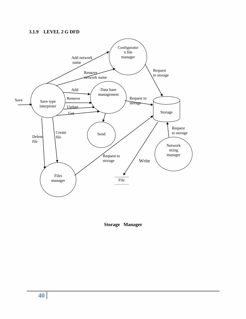
3.1.9 LEVEL 2 G DFD
Storage Manager
Configuratio
n file
manager
Files
manager
Storage
Send
File
Add network
name
Remove
network name
Request
to storage
Add
Remove
Update
Get
Save type
interpreter
Create
file Delete
file
Request to
storage
Request
to storage
Network
string
manager
Request to
storage
Data base
management
Write
Save

41
3.2 UML DIAGRAMS
3.2.1 Use Case Diagram
Basic User Interaction
add device
remove device
start device
stop device
add command
remove command
<<includes>>
add networkremove network
administrator
<<uses>>
<<uses>>
<<uses>>
<<uses>>
<<uses>>
<<uses>>
<<uses>>
<<uses>>
42
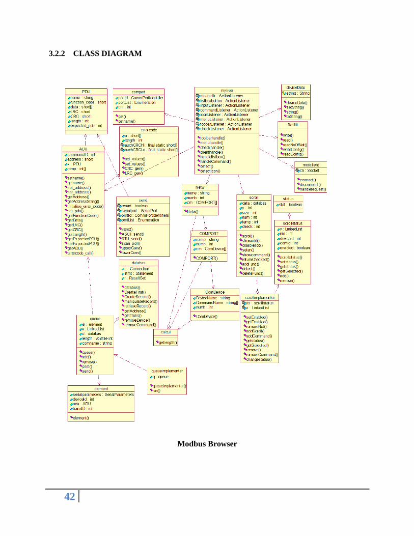
3.2.2 CLASS DIAGRAM
Modbus Browser
43
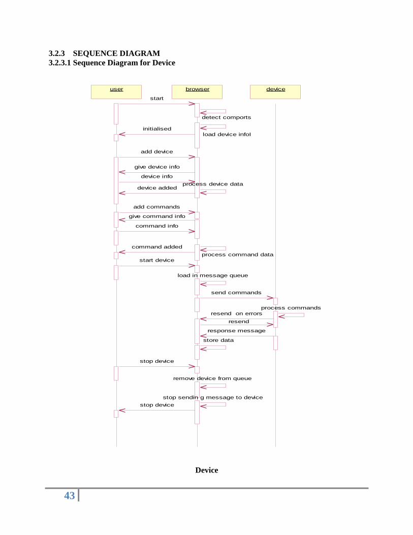
3.2.3 SEQUENCE DIAGRAM
3.2.3.1 Sequence Diagram for Device
Device
user browser device
start
detect comports
load device infoIinitialised
add device
give device info
device info
process device datadevice added
add commands
give command info
command info
process command data
command added
start device
load in message queue
send commands
process commandsresend on errors
resend
response message
store data
stop device
remove device from queue
stop sendin g message to device
stop device

44
3.2.3.2 Sequence Diagram for Network
Network
user config. Server Browser2
register on startup
register on startup
register browser
register browser
give network list
network list
start browser
add network
network list
select network
send selection give config. file
send config file
store and add network
start remotely start selection start string
start specified device
stop remotely stop selection stop string
stop specified device

45
3.2.4 ACTIVITY DIAGRAM
Activity Diagram for Modbus Browser
start
initial
device
added
command
added
network
added
get device info
save device
get command info
save_command
add device
add networkadd command
configurecontrol
send
commands
start
stop commands
stop
device
started
send start
device
stoped
send stop
continue
browser
closed
discontinue

46
3.2.5 STATE DIAGRAM
3.2.5.1 State Diagram for Master
Master

47
3.2.5.2 State Diagram for Slave
Sla
ve

48
3.2.6 COMPONENT DIAGRAM
Modbus Browser
mytree.
class modclient.
class
device_nam.
class
scroll.
classdatabas.
class
errorcode.
classqueueimplementer.
class
lineparser.
class ADU.class
queue.cla
ss
PDU.cla
ss

49
3.2.7 DEPLOYMENT DIAGRAM
Modbus Browser
PLC1 PLC2
Server
Modbus
Browser
Modbus
Browser
PLC3

50
3.3 Database Design:
MSACCESS has been used for storing database information. Following is design view of
the Database.
Table name: First
Field Name Data Type Description
address Number Device address
device_name Text Name of device
id Number Internal device id
nid Number Internal network id
noc Number Number of commands
tid Number Transmission id
1. ASCII
2. RTU
portname Text Name of port
baudRate Number Baud rate of port
flowControlIn Number -----
flowControlOut Number -----
databits Number Number of databits to be
sent
stopbits Number Stopbits to be sent
parity Number Parity (even or odd)
Table 3.1: The above table depicts information that will be stored by Modbus browser after
adding a new device

51
Table name: Second
Field name Data Type Description
Address Number Address of device
Name Text Name of device
commandID Number Internal command id
id Number Internal device id
nid Number Internal network id
portName Text Name of port
function_code Number Function code supported by
device
data1 Text Command data
data2 Text Command data
LRC Number Error code for ASCII mode
CRC1 Number Error code for RTU mode
CRC2 Number Error code for RTU mode
length Number Length of command
expected_pdu Number Return length
Filename Text Filename to store response
Table 3.2: The above table depicts the information to be stored about each command

52
Chapter 4
Implementation

53
4. Implementation
4.1 System Implementation
We have divided project into various parts. Following are some of the
major modules in our project.
1. Basic
2. Mytree
3. Scheduler
4. Server
5. Queue
6. Send
7. Databas
54
4.1.1 Basic:
This module contains basic classes for implementation of Modbus
protocol. They are ADU and PDU. ADU stands for Application Data Unit and PDU stands for
Protocol Data Unit. PDU is basically a command supported by each devices and ADU tells to
which device to send a specific PDU. One ADU may have more than one PDU. User has to enter
ADU only once. PDU will be attached to ADU automatically when it is entered.
4.1.2 Mytree:
This is central ActionListener, which listens to all user commands through
GUI, then process those request and handle them properly. It also connects to modserver to
connect to other modbus client. It handles all database requests and maintains correct
configuration file status. On startup it tries to connect to server, registers itself and sends
configuration string.
4.1.3 Scheduler:
This is a command dispatcher, which adds and removes commands from
the commands queue. When user starts or stops device, scheduler adds and removes those
commands from the queue.
4.1.4 Server:
The main purpose of server is to connect two or more Modbus browsers so
that they can control each other‟s device remotely. Server collects all configuration string of the
browsers and dispatches it to browsers who request other browser‟s configuration file.

55
4.1.5 Queue:
The purpose for queue is to hold commands to be sent to the device(s).
Queue essentially works as FIFO and sends commands first which were added first. Commands
are added and removed by scheduler.
4.1.6 Send:
Sends and receives commands from queue to the device. Error control is
done and if response is positive and with current checksum it is stored.
4.1.7 Databas:
Databas provides connectivity to MS-ACESS so that device info and
command info can be stored on hard disk. Databas uses standard ODBC-JDBC Bridge to
connect java to MS-ACCESS.

56
4.2 Data Dictionary
A data is an organized listing of all elements that are pertinent to the
system with precise rigorous definitions so that both the user and system analyst have common
understandings of inputs, outputs, components of stores and intermediate calculations. The data
dictionary compiles the characteristics of each data object and control item in a standard format.
4.2.1 File: basic.java
Class: PDU
Data Item Data Structure Type Description
Name String Name of command
Function_code short Corresponding function
code for a device
Data int [] Data area for a command
LRC short Calculate LRC for ASCII
mode
CRC short [] Calculate CRC for RTU
mode
Length int Length of PDU
Expected_pdu int Expected length of response
string
Class: ADU
Data Item Data Structure Type Description CommandId Int Internal command ID for a
command
Address short Device Address
X PDU Stores command
information
Temp int [] Calculate CRC and LRC

57
4.2.2 device.java
Data Item
Data Structure Type Description
adu ADU Store device information
Name String Name of device
ID int Device ID
transID int Transmission ID
4.2.3 deviceData.java
Data Item Data Structure Type Description
String String Stores name of node
4.2.4 errorcode.java
Data Item Data Structure Type Description
A short [] Stores ADU
Length int Stores length of ADU auchCRCHi private final static
short [] Lookup table
AuchCRCLo private final static
short [] Lookup table
4.2.5 lineparser.java
Class: Netw
Data Item Data Structure Type Description
Name String Name of network
Numb int Number of comports
Cm COMPORT [] Stores info about comports
Class: COMPORT
Data Item Data Structure Type Description
name String Name of comports
numb int Number of devices
Cm ComDevice [] Stores info about devices
Class: ComDevice
Data Item Data Structure Type Description
DeviceName String Name of device
numb int Number of commands
CommandName String Stores info about

58
commands
4.2.6 databas.java
4.2.7 mytree.java
Data Item Data Structure Type Description
jt JTree A control that displays a set of
hierarchical data on the left of mytree.
Mb JMenuBar Displays menu bar at the top of mytree.
Jpopupmenu JPopupMenu A small window which pops up and
displays a series of choices.
mousclik ActionListener Listens popup menu.
listboxbutton ActionListener Listens list box.
inputListener ActionListener Listens input given.
commandListener ActionListener Listens device_nam class.
actionListener ActionListener Listens scroll1 class.
iconListener ActionListener Listens icon panel.
menuListener ActionListener Listens menu items.
toolbarListener ActionListener Listens toolbar items.
checkListener ActionListener Listens for device commands being
checked.
4.2.8 SerialParameters.java
Data Item Data Structure Type Description
portName String Specifies the port name to be connected
to.
baudRate int Specifies baud rate for modbus device.
flowControlIn int Specifies flowControlIn for port.
url String Specifies the database driver name.
Data Item Data Structure Type Description
Conn Connection Opens connection with database.
Res ResultSet Provides access to a table of data. Holds
the recordset.
Stmt Statement Object used for executing a static SQL
statement and obtaining the results
produced by it.
url String Specifies the database driver name.

59
flowControlOut int Specifies flowControlOut for port.
databits int Specifies no of data bits to be send in a
packet.
stopbits int Specifies the no of stop bits for modbus
protocol.
parity int Specifies no of parity bits for modbus
protocol.
4.3 ALGORITHM
4.3.1 Algorithm: LineParser
Objective:
Separate out network name, com port names, device names and command names in
configuration string
Level 1: Separate network name
1. Detect index of “{“. Put it in closeIndex.
2. Substring from start of configuration string to closeIndex is name of network.
Level 2: Separate Comport name
1. Detect index of “{“.Put it in startIndex.
2. if “}” detected, put it in closeIndex
3. if(closeIndex-startIndex) then no comports goto exit
4. Detect index of “(“.Put it in closeIndex.
5. Substring (startIndex, closeIndex) is new comport name.
6. Repeat for delimiter “/”.
Level 3: Separate Device name (Repeated for each COM ports)
1. Detect index of “(“.Put it in startIndex.
2. if “)” detected, put it in closeIndex
3. if(closeIndex-startIndex) then no devices goto exit

60
4. Detect index of “[“.Put it in closeIndex.
5. Substring (startIndex, closeIndex) is new device name.
6. Repeat for delimiter “,”.
Level 2: Separate Command name (Repeated for each device)
1. Detect index of “[“.Put it in startIndex.
2. if “]” detected, put it in closeIndex
3. if(closeIndex-startIndex) then no commands goto exit
4. Detect index of “#“.Put it in closeIndex.
5. Substring (startIndex, closeIndex) is new command name.
6. Repeat for delimiter “#”.
4.3.2 Algorithm: comportIdentification
Objective: Detect number of comports on your PC and their names
Number of comports:
1. Enumeration portlist = getPortIdentifiers ().
2. counter = 0.
3. while portlist has more Elements
3.1 if port type is Serial then counter ++
1. return counter

61
Name of comports:
Input: Index
1. Enumeration portlist = getPortIdentifiers().
2. counter = 0.
3. while portlist has more elements
3.1 if port type is Serial
3.1.1 if Input == counter return name of comport
3.1.2 counter++
4.3.3 Algorithm: removeDevice
Objective: remove device name from configuration file, database and tree structure
Level 1: remove device name from configuration file
1. Search name of device in configuration file.
2. Note startIndex and closeIndex of name.
3. Remove it from configuration string.
4. Restore the string.
Level 2: remove device name from database
1. Get deviceId
2. Delete device records using DELETE command of SQL both in first and second
table.
Level 3: remove device name from tree structure
1. Get Last Selected path component.
2. Remove device node from its parent node using TreeModel.

62
3. Set Selection path to comport name.
4.3.4 Algorithm: removeNetwork
Objective: remove network from configuration.mod and delete Network Configuration file
1. Determine networkId (i.e. child number of root) and store in numb.
2. Read configuration.mod.
3. Get filename from numb (th) string.
4. delete that file.
5. remove that filename from configuration.mod.
4.3.5 Algorithm: deleteCommand
Objective: delete command from Network Configuration file and device database
1. Search for command name in Network configuration file.
2. Store startIndex and closeIndex of Command Name.
3. Create new string excluding command name to be deleted.
4. get commandId to be deleted( Index of checkbox in panel )
5. Remove it from database using DELETE command of SQL for deviceId and
commandId
6. remove checkbox from panel
63
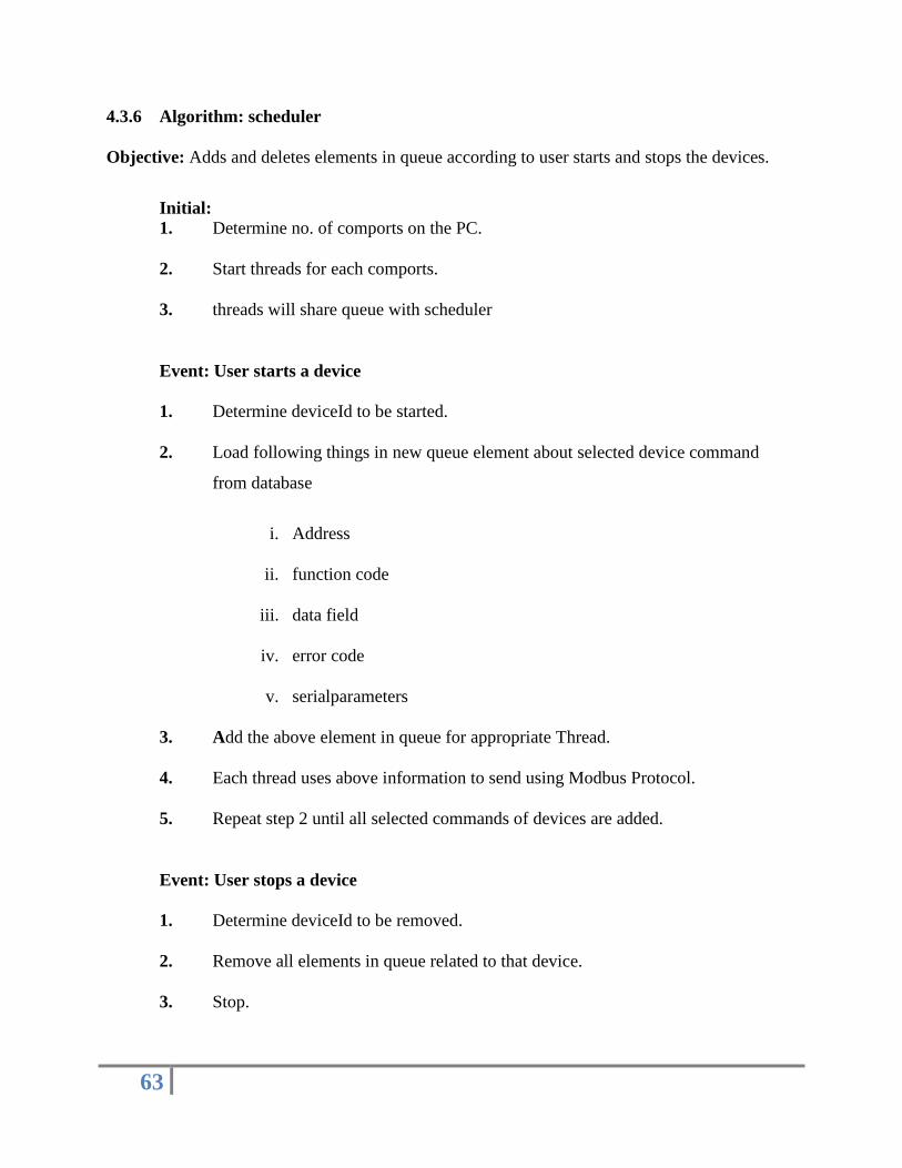
4.3.6 Algorithm: scheduler
Objective: Adds and deletes elements in queue according to user starts and stops the devices.
Initial:
1. Determine no. of comports on the PC.
2. Start threads for each comports.
3. threads will share queue with scheduler
Event: User starts a device
1. Determine deviceId to be started.
2. Load following things in new queue element about selected device command
from database
i. Address
ii. function code
iii. data field
iv. error code
v. serialparameters
3. Add the above element in queue for appropriate Thread.
4. Each thread uses above information to send using Modbus Protocol.
5. Repeat step 2 until all selected commands of devices are added.
Event: User stops a device
1. Determine deviceId to be removed.
2. Remove all elements in queue related to that device.
3. Stop.

64
4.3.7 Algorithm: showIcons
Objective: Show icons on right side for network, comports, devices
Input: String Array of networks/comports/devices
1. Remove previous icons
2. Add button with a specified gif image
3. give name to button from string array

65
4.3.8 Algorithm: Master to Master Connection
Initial: Server side
1. Listen for connections.
2. Device registers itself.
3. Add Client Socket in connection Vector.
4. Start a new Thread for that client.
5. Accept configuration string from this client.
6. Listen for requests.
Initial: Client side
1. Connect to server using client socket at startup.
2. Send configuration string.
3. Listen for requests.
Event: User requests Network List
Server:
1. Server retrieves device Sockets from connection Vector.
2. Add device name and IP address in a string and sends it.
Client:
1. Receives Network List.
2. Displays it.

66
Event: User selects a Master out of Network list
Server:
1. Server interprets request String and separates out IP address.
2. Selects corresponding socket thread and sends configuration String.
Client:
1. Client receives configuration string.
2. Stores this configuration string in a file.
3. Client makes changes in configuration.mod.
Event: Master1 starts commands of Master2
Client1:
1. Prepare a string with IP address of Master2 plus name of comport selected,
Device ID and commands selected.
2. Send this start string to server.
Server:
1. Accept the above string from Client 1.
2. Extract IP address of Client2.
3. Select Socket of corresponding Client2 and send this String.
Client2:
1. Client2 accepts the above start string.
2. Checks if commands already started.
3. If “yes” skip else add that command in queue.
4. Repeat step 3 until command list ends.

67
Event: Master1 stops commands of Master2
Client1:
1. Prepare a string with IP address of Master2 plus name of comport selected,
Device ID and commands selected.
2. Send this stop string to server.
Server:
1. Accept the above string from Client 1.
2. Extract IP address of Client2.
3. Select Socket of corresponding Client2 and send this String.
Client2:
1. Client2 accepts the above start string.
2. Checks if commands already started.
3. Remove that command in queue.
4. Repeat step 3 until command lists ends.
Event: Master exits or Disconnects
Client:
1. Client sends “Remove me” string.
Server:
2. Server determines source of “Remove me”.
3. Removes Socket from connection Vector.
4. Thread for Client terminates.

68
4.3.9 Algorithm: errorcode
Objective: Generate LRC and CRC codes
LRC: Input ADU string
1. LRC = 0
2. I = 0
3. while ( I < lengthOf(ADU string))
a. LRC += charAt ( I ) of ADU string
b. I++
4. return LRC
CRC: Input ADU string
1. CRC[] = {0xFF , 0xFF} // stores CRC
2. nextShort = 0
3. I = 0
4. while( I < length )
a. nextShort = 0xFF & (charAt(I) of ADU string)
b. uIndex = CRC [0] XOR nextshort
c. CRC [0] = CRC [1] XOR auchCRCHi [uIndex]
d. CRC [1] = auchCRCLo [uIndex]
5. CRC [0] = CRC [0] & 0xff
6. CRC [1] = CRC [1] & 0xff
7. Return CRC

69
Reference Tables:
auchCRCHi
short [] auchCRCHi = {
0x00, 0xC1, 0x81, 0x40, 0x01, 0xC0, 0x80, 0x41, 0x01, 0xC0,
0x80, 0x41, 0x00, 0xC1, 0x81, 0x40, 0x01, 0xC0, 0x80, 0x41,
0x00, 0xC1, 0x81, 0x40, 0x00, 0xC1, 0x81, 0x40, 0x01, 0xC0,
0x80, 0x41, 0x01, 0xC0, 0x80, 0x41, 0x00, 0xC1, 0x81, 0x40,
0x00, 0xC1, 0x81, 0x40, 0x01, 0xC0, 0x80, 0x41, 0x00, 0xC1,
0x81, 0x40, 0x01, 0xC0, 0x80, 0x41, 0x01, 0xC0, 0x80, 0x41,
0x00, 0xC1, 0x81, 0x40, 0x01, 0xC0, 0x80, 0x41, 0x00, 0xC1,
0x81, 0x40, 0x00, 0xC1, 0x81, 0x40, 0x01, 0xC0, 0x80, 0x41,
0x00, 0xC1, 0x81, 0x40, 0x01, 0xC0, 0x80, 0x41, 0x01, 0xC0,
0x80, 0x41, 0x00, 0xC1, 0x81, 0x40, 0x00, 0xC1, 0x81, 0x40,
0x01, 0xC0, 0x80, 0x41, 0x01, 0xC0, 0x80, 0x41, 0x00, 0xC1,
0x81, 0x40, 0x01, 0xC0, 0x80, 0x41, 0x00, 0xC1, 0x81, 0x40,
0x00, 0xC1, 0x81, 0x40, 0x01, 0xC0, 0x80, 0x41, 0x01, 0xC0,
0x80, 0x41, 0x00, 0xC1, 0x81, 0x40, 0x00, 0xC1, 0x81, 0x40,
0x01, 0xC0, 0x80, 0x41, 0x00, 0xC1, 0x81, 0x40, 0x01, 0xC0,
0x80, 0x41, 0x01, 0xC0, 0x80, 0x41, 0x00, 0xC1, 0x81, 0x40,
0x00, 0xC1, 0x81, 0x40, 0x01, 0xC0, 0x80, 0x41, 0x01, 0xC0,
0x80, 0x41, 0x00, 0xC1, 0x81, 0x40, 0x01, 0xC0, 0x80, 0x41,
0x00, 0xC1, 0x81, 0x40, 0x00, 0xC1, 0x81, 0x40, 0x01, 0xC0,
0x80, 0x41, 0x00, 0xC1, 0x81, 0x40, 0x01, 0xC0, 0x80, 0x41,
0x01, 0xC0, 0x80, 0x41, 0x00, 0xC1, 0x81, 0x40, 0x01, 0xC0,
0x80, 0x41, 0x00, 0xC1, 0x81, 0x40, 0x00, 0xC1, 0x81, 0x40,
0x01, 0xC0, 0x80, 0x41, 0x01, 0xC0, 0x80, 0x41, 0x00, 0xC1,
0x81, 0x40, 0x00, 0xC1, 0x81, 0x40, 0x01, 0xC0, 0x80, 0x41,
0x00, 0xC1, 0x81, 0x40, 0x01, 0xC0, 0x80, 0x41, 0x01, 0xC0,
0x80, 0x41, 0x00, 0xC1, 0x81, 0x40
}
auchCRCLo
short[] auchCRCLo = {
0x00, 0xC0, 0xC1, 0x01, 0xC3, 0x03, 0x02, 0xC2, 0xC6, 0x06,
0x07, 0xC7, 0x05, 0xC5, 0xC4, 0x04, 0xCC, 0x0C, 0x0D, 0xCD,
0x0F, 0xCF, 0xCE, 0x0E, 0x0A, 0xCA, 0xCB, 0x0B, 0xC9, 0x09,
0x08, 0xC8, 0xD8, 0x18, 0x19, 0xD9, 0x1B, 0xDB, 0xDA, 0x1A,
0x1E, 0xDE, 0xDF, 0x1F, 0xDD, 0x1D, 0x1C, 0xDC, 0x14, 0xD4,
0xD5, 0x15, 0xD7, 0x17, 0x16, 0xD6, 0xD2, 0x12, 0x13, 0xD3,
0x11, 0xD1, 0xD0, 0x10, 0xF0, 0x30, 0x31, 0xF1, 0x33, 0xF3,
0xF2, 0x32, 0x36, 0xF6, 0xF7, 0x37, 0xF5, 0x35, 0x34, 0xF4,

70
0x3C, 0xFC, 0xFD, 0x3D, 0xFF, 0x3F, 0x3E, 0xFE, 0xFA, 0x3A,
0x3B, 0xFB, 0x39, 0xF9, 0xF8, 0x38, 0x28, 0xE8, 0xE9, 0x29,
0xEB, 0x2B, 0x2A, 0xEA, 0xEE, 0x2E, 0x2F, 0xEF, 0x2D, 0xED,
0xEC, 0x2C, 0xE4, 0x24, 0x25, 0xE5, 0x27, 0xE7, 0xE6, 0x26,
0x22, 0xE2, 0xE3, 0x23, 0xE1, 0x21, 0x20, 0xE0, 0xA0, 0x60,
0x61, 0xA1, 0x63, 0xA3, 0xA2, 0x62, 0x66, 0xA6, 0xA7, 0x67,
0xA5, 0x65, 0x64, 0xA4, 0x6C, 0xAC, 0xAD, 0x6D, 0xAF, 0x6F,
0x6E, 0xAE, 0xAA, 0x6A, 0x6B, 0xAB, 0x69, 0xA9, 0xA8, 0x68,
0x78, 0xB8, 0xB9, 0x79, 0xBB, 0x7B, 0x7A, 0xBA, 0xBE, 0x7E,
0x7F, 0xBF, 0x7D, 0xBD, 0xBC, 0x7C, 0xB4, 0x74, 0x75, 0xB5,
0x77, 0xB7, 0xB6, 0x76, 0x72, 0xB2, 0xB3, 0x73, 0xB1, 0x71,
0x70, 0xB0, 0x50, 0x90, 0x91, 0x51, 0x93, 0x53, 0x52, 0x92,
0x96, 0x56, 0x57, 0x97, 0x55, 0x95, 0x94, 0x54, 0x9C, 0x5C,
0x5D, 0x9D, 0x5F, 0x9F, 0x9E, 0x5E, 0x5A, 0x9A, 0x9B, 0x5B,
0x99, 0x59, 0x58, 0x98, 0x88, 0x48, 0x49, 0x89, 0x4B, 0x8B,
0x8A, 0x4A, 0x4E, 0x8E, 0x8F, 0x4F, 0x8D, 0x4D, 0x4C, 0x8C,
0x44, 0x84, 0x85, 0x45, 0x87, 0x47, 0x46, 0x86, 0x82, 0x42,
0x43, 0x83, 0x41, 0x81, 0x80, 0x40
}

71
Chapter 5
Testing

72
5 Testing
5.1 Test Plan:
Software Testing is the procedure that is conducted to uncover the errors
that were made inadvertently as it was designed and constructed. Testing is the set of activity
that can be planned in advanced and conducted systematically. For this reason a template for
software testing -a set of steps into which we can specify test case design techniques and testing
methods-should be defined for the software process.
“Testing is the unavoidable part of any responsible effort to develop a
software system “.
A strategy for software testing may also be viewed in the context of the
spiral. Unit testing begins at the vortex of the spiral and concentrates on each unit of the software
as implemented in the source code. Testing progresses by moving outward along the spiral to
integration testing, where the focus is on design and the construction of the software
architecture. Taking another turn outward on the spiral, we encounter validation testing, where
requirements are established as part of software requirement analysis are validated against the
software that has been constructed. Finally, we arrive at the system testing, where the software
and other system elements are tested as whole. To test computer software, we spiral out along
streamlines that broaden the scope of testing each turn.

73
5.1.1 Unit Testing:-
Unit testing focuses verification effort on the smallest unit of software
design-the software component or module. Using the component-level design description as a
guide, important control paths are tested to uncover errors within the boundary of the module.
The relative complexity of the tests and the errors those tests uncover is limited by the
constrained scope established for unit testing. The unit test focuses on the internal processing
logic and data structures within the boundaries of a component. This type of testing can be
conducted in parallel for multiple components.
The module interface is tested to ensure that information is properly flows
into and out of program unit under text. Local data structures are examined to ensure that data
stored temporarily maintains its integrity during all steps in an algorithm‟s execution. All
independent paths (basic paths) through the control structure are exercised to ensure that all
statements in a module operate properly at boundaries established to limit or restrict processing.
And finally, all errors handling paths are tested. Following are test cases performed by us.
5.1.1.1 Mytree:
Objective:
This class acts as the action listener for all the action that takes place in the
main browser such as adding and deleting the network from LAN, adding new devices (soft
PLC‟s) or removing the devices (soft PLC‟s) from the COM ports, which are detected by the
com port identifier, adding new commands to the device and removing the command for the
device of the default network.
74
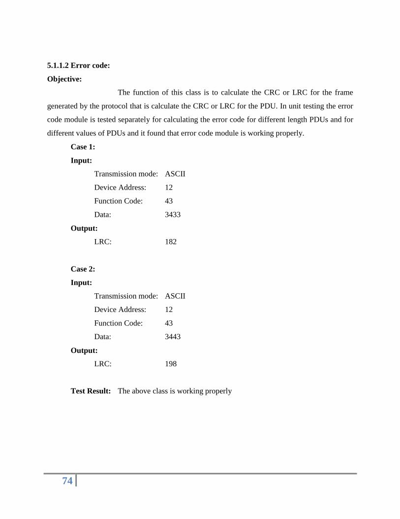
5.1.1.2 Error code:
Objective:
The function of this class is to calculate the CRC or LRC for the frame
generated by the protocol that is calculate the CRC or LRC for the PDU. In unit testing the error
code module is tested separately for calculating the error code for different length PDUs and for
different values of PDUs and it found that error code module is working properly.
Case 1:
Input:
Transmission mode: ASCII
Device Address: 12
Function Code: 43
Data: 3433
Output:
LRC: 182
Case 2:
Input:
Transmission mode: ASCII
Device Address: 12
Function Code: 43
Data: 3443
Output:
LRC: 198
Test Result: The above class is working properly

75
5.1.1.3 Line parser:
Objective:
The input to line parser is the configuration file which contains name of
network, comports, devices it supports and commands supported by it. It smartly separates out
these components and stores them in proper variables.
Input:
network0{COM1()/COM2()}
Output:
Name of network: network0
Number of Serial ports: 2
Name of Serial ports: COM1, COM2
Number of devices under COM1: 0
Number of devices under COM1: 0
Input:
network0{COM1(PLC[])/COM2()}
Output:
Name of network: network0
Number of Serial ports: 2
Name of Serial ports: COM1, COM2
Number of devices under COM1: 1
Number of devices under COM1: nil
Name of device under COM1: PLC
Number of commands under PLC: 0
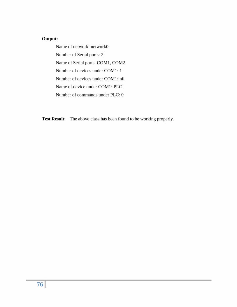
Input:
network0{COM1(PLC[])/COM2()}
76
Output:
Name of network: network0
Number of Serial ports: 2
Name of Serial ports: COM1, COM2
Number of devices under COM1: 1
Number of devices under COM1: nil
Name of device under COM1: PLC
Number of commands under PLC: 0
Test Result: The above class has been found to be working properly.

77
5.1.1.4 fileUtil:
Objective:
This class provides functionality to save configuration files and
configuration strings. Following is testing done on it.
Name of Function:
Write:
Objective: writes to network configuration file.
Input: filename, data
Type of file: Random Access File
Test Input:
Filename: network0.mod
Data: network0{COM1(PLC[])/COM2()}
Test Result: network0{COM1(PLC[])/COM2()} written successfully in file with
filename network0.mod.
Name Of Function:
Read:
Objective: writes to network configuration file.
Input: filename
Return: Data
Type of file: Random Access File
Test Input:
Filename: network0.mod
Data in file: network0{COM1(PLC[])/COM2()}
Test Result: network0{COM1(PLC[])/COM2()} returned successfully from file with
filename network0.mod.
78
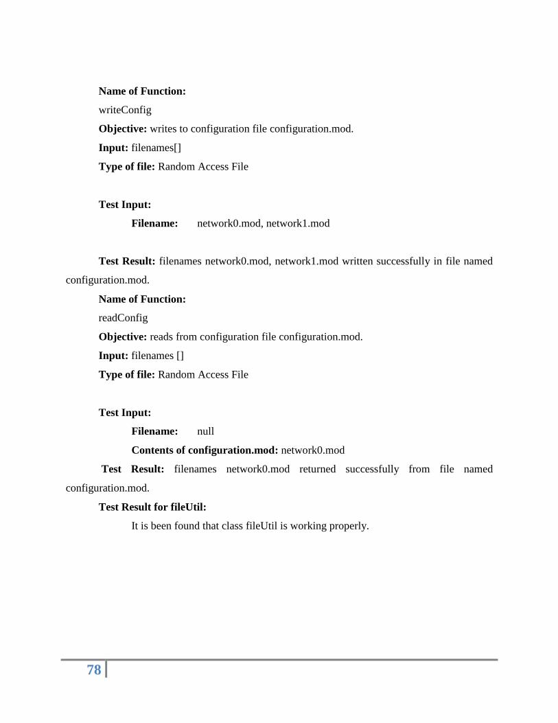
Name of Function:
writeConfig
Objective: writes to configuration file configuration.mod.
Input: filenames[]
Type of file: Random Access File
Test Input:
Filename: network0.mod, network1.mod
Test Result: filenames network0.mod, network1.mod written successfully in file named
configuration.mod.
Name of Function:
readConfig
Objective: reads from configuration file configuration.mod.
Input: filenames []
Type of file: Random Access File
Test Input:
Filename: null
Contents of configuration.mod: network0.mod
Test Result: filenames network0.mod returned successfully from file named
configuration.mod.
Test Result for fileUtil:
It is been found that class fileUtil is working properly.

79
5.1.2 Integration Testing:-
Integration testing is the systematic technique for constructing the
software architecture while at the same time conducting tests to uncover the errors associated
with interfacing. The objective is to take unit tested components and build a program structure
that has been dedicated design.
There are different integration method are presents as follows :
Top-down integration: Top-down integration testing is an incremental approach to construction
of the software architecture. Modules are integrated by moving downward through the control
hierarchy, begins with the main program.
Bottom-up integration: Bottom-up integration testing, as its name implies, begins construction
and testing with atomic modules.
Regression testing: Each time a new module is added as a part of integration testing, the
software changes.
Smoke testing: Smoke testing is an integration testing approach that is commonly used when
software products are being developed.
We are using bottom-up integration testing. The modules are incorporate
together and called from main routine. The inputs of each module are kept track of and are
available till application ends. The purpose of this testing is to check the software for bugs
during its navigation through various levels built in the form of routines. The input from every
routine should reach the higher routines, also graph should not be corrupted on the way through
the routines even when previous processes executing. Hence, the software should perform for
several applications irrespective of any previous application in execution.

80
Care was taken for the following things:
1. The capability of the modules in their input parameters and return values.
2. The correctness of the overall system architecture being realized
3. Any manipulation of the data in the interfaces
4. The effectiveness of the combined modules
5. Interface integrity
6. Functional validity
7. Information content
8. performance
5.1.2.1 Bottom-up Testing:
As stated earlier in Bottom-up testing lower level modules in hierarchy are
tested first until final module is tested.
Bottom-Up integration strategy may be implemented with the following
steps:
1. Low-level components are combined into clusters (sometimes called builds) that
perform a specific software sub function.
2. A driver (a control program for testing) is written to coordinate test case input and
output.
3.The cluster is tested.
4. Drivers are removed and clusters are combined moving upward in the program
structure.

81
Fig.5.1 Bottom-up Integration testing for sending commands to devices
Explanation:
Send:
Initially the send module is tested which works closely at device level to
send data serially using java comm Api. It gets input from Queueimplementer. For test
conditions data can be manually sent. Data can be tested on receiver computer using serial port
testing softwares.
Queue implementer:
Queue implementer consist of a queue in which device commands are
added and which are sent to Send module which safely transmits it to the device.
Queueimplementer
send
Mytree
scheduler

82
Scheduler:
Scheduler adds and removes from queue in command implementer. Java‟s
inbuilt semaphore technique is used to allow synchronized access to queue.
Mytree:
Mytree Listens to user inputs and on pressing of start button uploads the
command from database and sends it to the scheduler.
Test Result: The above modules are found to be firmly integrated with each other.
5.1.3Validation Testing
After all the errors are removed and integration testing is completed,
the validation testing begins. It can be defined as validation succeeds when software
functions in a manner that can be reasonably expected by the customer.
Does project matches the problem statement defined?
The project is exactly as was specified in the problem statement submitted at the
beginning of the project.
Does the functionally matches the SRS?
The project works exactly as in defined in the SRS. The behavior of each of the modules
is, as was given in the SRS.
After each validation test has been conducted, the function or
performance characteristic conforms to specification and is accepted.

83
5.1.3.1 Validation testing for User Interface:
User Interface was built in Java swing. All swing components were
found to be working correctly.
5.1.3.2 Validation testing for Device Management System:
All validation has been performed on this system. Device addition,
deletion, modification has been performed successfully. Commands when added, deleted
works fine with system. The database system works smoothly and corresponding changes to
configuration string are performed correctly.

84
Chapter 6
Result

85
6. RESULT:
6.1 Modbus Browser:
Fig 6.1: Front end.

86
6.2 Default Network:
Fig 6.2: Default Network: network0.
Configuration file: network0{COM1()/COM2()}
Configuration file being created for the default network (network0).
Adding of device:
Fig 6.3: Device to be added to COM1 port of default network.

87
Fig 6.4: Add device popup window.
First
address device_name id nid noc tid portName baudRate flowControlIn flowControlOut databits stopbits parity
1 PLC 0 0 0 1 COM1 19200 0 0 8 1 2
Fig 6.5: Updated Database: Table first is updated with every device added.
Configuration file: network0{COM1(PLC[])/COM2()}
88
Contents of configuration file being updated after adding the device (PLC) to COM1 port of
network0.
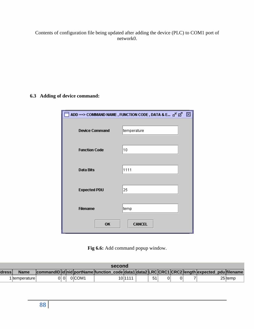
6.3 Adding of device command:
Fig 6.6: Add command popup window.
second
address Name commandID id nid portName function_code data1 data2 LRC CRC1 CRC2 length expected_pdu filename
1 temperature 0 0 0 COM1 10 1111 51 0 0 7 25 temp

89
Fig 6.7: Updated Database: Table second is updated with every device command added.
Configuration file: network0{COM1(PLC[temperature])/COM2()}
Contents of configuration file being updated after adding device command (temperature) to PLC.
Fig 6.8: Device Added (PLC) to COM1 port of network0 and temperature is the device
command for PLC.

90
6.4 Communication with device:
Fig 6.9: After selecting the temperature command and clicking the start button the following
data given below is send to PLC at the respective address.

91
Fig 6.10: Data send to PLC.
Baud Rate 19200
Flow control in None
Flow control out None
data bits 8
stop bits 1
Parity Bits Even
device Index 0
ADU 110111133
Port names COM1
Baud Rate 19200
Flow control in None
Flow control out None
data bits 8
stop bits 1
Parity Bits Even
device Index 0
ADU 110111133
Port names COM1
Baud Rate 19200
Flow control in None
Flow control out None
data bits 8
stop bits 1
Parity Bits Even

92
6.5 Device Information:
Fig 6.11: View device information.

93
Fig 6.12: Window displaying device information.
6.6 Configure device:
Fig 6.13: Configure device.
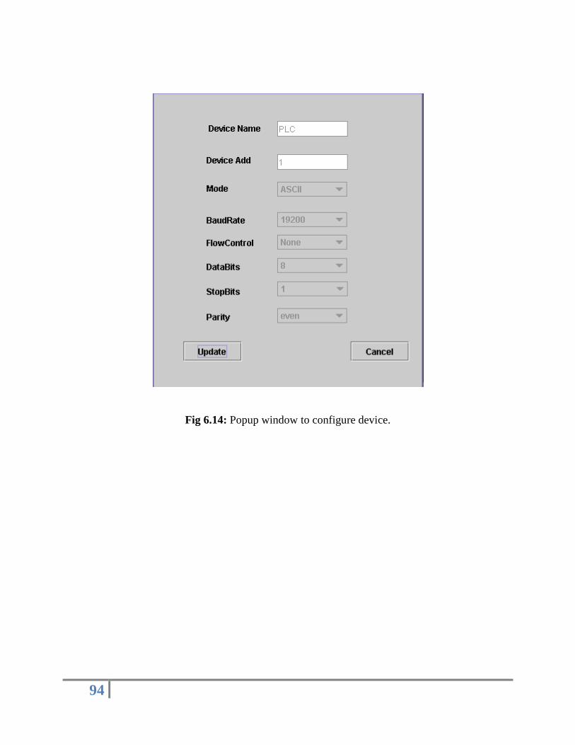
94
Fig 6.14: Popup window to configure device.
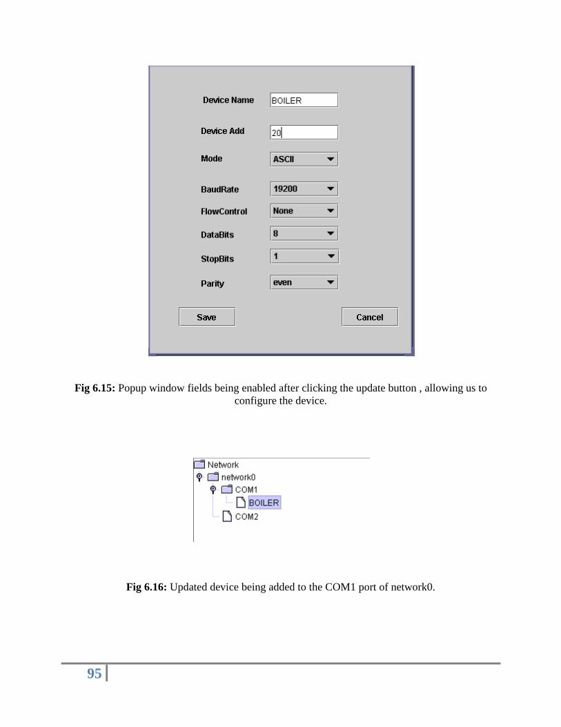
95
Fig 6.15: Popup window fields being enabled after clicking the update button , allowing us to
configure the device.
Fig 6.16: Updated device being added to the COM1 port of network0.

96
Fig 6.17: Updated Database: Table first is updated with every device configured.
Fig 6.18: Updated Database: Table second is updated with every device configured.
Configuration file: network0{COM1(BOILER[temperature])/COM2()}
Contents of configuration file being updated after configuring the device.
first address device_name id nid noc tid portName baudRate flowControlIn flowControlOut databits stopbits parity
20 BOILER 0 0 0 1 COM1 19200 0 0 8 1 2
second
address name commandID id nid portName function_code data1 data2 LRC CRC1 CRC2 length expected_pdu filename
20 temperature 0 0 0 COM1 10 1111 51 0 0 7 25 temp

97
6.7 Remove Device:
Fig 6.19: Removal of device connected to a COM port.
Fig 6.20: Network0 been updated after device (BOILER) has been removed from COM1 port.

98
Fig 6.21: Updated Database: Table first is updated with every device being removed.
Fig 6.22: Updated Database: Table second is updated with every device being removed.
Configuration file: network0{COM1()/COM2()}
Contents of configuration file being updated after removing the device(BOILER) from COM1
port of network0.
first address device_name id nid noc tid portName baudRate flowControlIn flowControlOut databits stopbits parity
Second
address name commandID id nid portName function_code data1 data2 LRC CRC1 CRC2 length expected_pdu filename

99
Chapter 7
Conclusion

100
7.1 Conclusions
Modbus Browser has been implemented successfully which fulfills all requirements.
Thus we have developed a Device Manager which can manage Modbus devices correctly.
Modbus protocol has been implemented which is utilized by this browser to communicate with
this device.
7.2 Applications of the System
Graphical Device Manager helps to manage device properly.
Any serial communication Modbus device can be connected to the system.
This uses polling method and separate thread for each port is used to
communicate with devices.
7.3 Limitations
System being generic can‟t support specific functions of devices like sending a
single command only once.
A real time graph cannot be created because of varying nature of incoming data
from devices.
No network security for master to master connection.
7.4 Future Scopes
Efforts can be put in to develop a real time graph which takes varying length of
input and displays information real time.
Master to Master can be made more secured and put in many more features like
transferring real time data remotely.

101
Chapter 8
Bibliography

102
8. BIBLIOGRAPHY
8.1 Books:
1. THE UNIFIED MODELING LANGUAGE – USER GUIDE
- Grady Booch
- James Rumbaugh
- Ivar Jacobson
2. Core Java 2 Volume I-Fundamentals
- Cay S. Horstmann , Gary Cornell
3. JAVA 2 – BLACK BOOK
- Steven Holzner
4. JAVA 2 – THE COMPLETE REFERENCE
- Herbert Schildt
8.2 Web Sites:
1. www.modbus.org
2. http://www.modbus.org/docs/Modbus_Application_Protocol_V1_1b.pdf
3. www.modicon.com
4. www.java.sun.com